US4885903A - Safety interlock for lawn mowers - Google Patents
Safety interlock for lawn mowersDownload PDFInfo
- Publication number
- US4885903A US4885903AUS07/224,925US22492588AUS4885903AUS 4885903 AUS4885903 AUS 4885903AUS 22492588 AUS22492588 AUS 22492588AUS 4885903 AUS4885903 AUS 4885903A
- Authority
- US
- United States
- Prior art keywords
- safety interlock
- engine
- lawn mower
- lever
- levers
- Prior art date
- Legal status (The legal status is an assumption and is not a legal conclusion. Google has not performed a legal analysis and makes no representation as to the accuracy of the status listed.)
- Expired - Fee Related
Links
- 230000033001locomotionEffects0.000claimsdescription7
- 230000008878couplingEffects0.000claimsdescription2
- 238000010168coupling processMethods0.000claimsdescription2
- 238000005859coupling reactionMethods0.000claimsdescription2
- 230000005540biological transmissionEffects0.000abstractdescription9
- 230000007935neutral effectEffects0.000abstractdescription5
- 230000000295complement effectEffects0.000abstract1
- 230000007794irritationEffects0.000description4
- 230000000712assemblyEffects0.000description1
- 238000000429assemblyMethods0.000description1
- 230000003993interactionEffects0.000description1
Images

Classifications
- A—HUMAN NECESSITIES
- A01—AGRICULTURE; FORESTRY; ANIMAL HUSBANDRY; HUNTING; TRAPPING; FISHING
- A01D—HARVESTING; MOWING
- A01D34/00—Mowers; Mowing apparatus of harvesters
- A01D34/01—Mowers; Mowing apparatus of harvesters characterised by features relating to the type of cutting apparatus
- A01D34/412—Mowers; Mowing apparatus of harvesters characterised by features relating to the type of cutting apparatus having rotating cutters
- A01D34/63—Mowers; Mowing apparatus of harvesters characterised by features relating to the type of cutting apparatus having rotating cutters having cutters rotating about a vertical axis
- A01D34/67—Mowers; Mowing apparatus of harvesters characterised by features relating to the type of cutting apparatus having rotating cutters having cutters rotating about a vertical axis hand-guided by a walking operator
- A01D34/68—Mowers; Mowing apparatus of harvesters characterised by features relating to the type of cutting apparatus having rotating cutters having cutters rotating about a vertical axis hand-guided by a walking operator with motor driven cutters or wheels
- A01D34/6806—Driving mechanisms
- A—HUMAN NECESSITIES
- A01—AGRICULTURE; FORESTRY; ANIMAL HUSBANDRY; HUNTING; TRAPPING; FISHING
- A01D—HARVESTING; MOWING
- A01D34/00—Mowers; Mowing apparatus of harvesters
- A01D34/01—Mowers; Mowing apparatus of harvesters characterised by features relating to the type of cutting apparatus
- A01D34/412—Mowers; Mowing apparatus of harvesters characterised by features relating to the type of cutting apparatus having rotating cutters
- A01D34/63—Mowers; Mowing apparatus of harvesters characterised by features relating to the type of cutting apparatus having rotating cutters having cutters rotating about a vertical axis
- A01D34/67—Mowers; Mowing apparatus of harvesters characterised by features relating to the type of cutting apparatus having rotating cutters having cutters rotating about a vertical axis hand-guided by a walking operator
- A01D34/68—Mowers; Mowing apparatus of harvesters characterised by features relating to the type of cutting apparatus having rotating cutters having cutters rotating about a vertical axis hand-guided by a walking operator with motor driven cutters or wheels
- A01D2034/6843—Control levers on the handle of the mower
- A—HUMAN NECESSITIES
- A01—AGRICULTURE; FORESTRY; ANIMAL HUSBANDRY; HUNTING; TRAPPING; FISHING
- A01D—HARVESTING; MOWING
- A01D2101/00—Lawn-mowers
Definitions
- This inventionrelates to lawn mowers and safety interlock systems for power lawn mowers in particular.
- Conventional safety interlock systemsgenerally include a lever or bar located on the upper portion of the operating handle which must be pivoted downwardly into engagement and held against the handle grips before the drive wheels and cutter blades can be coupled to the engine.
- prior art safety interlock systemstend to cause operator hand fatigue and irritation when operated for long periods of time, such as in the case of commercial lawn mowers.
- a further object of the inventionis to provide a safety interlock system for power lawn mowers which does not cause operator hand fatigue or irritation when operated for long periods of time.
- the inventioncomprises an improvement for lawnmowers having an engine for driving at least a cutter blade or both a cutter blade and drive wheels, first and second clutch means for coupling and disengaging the cutter blade and drive wheels respectively to and from said engine, safety interlock means operable in a first position to maintain the engine in operation and in a second position to deactivate the engine when the cutter blade or drive wheels are coupled to the engine, and handle means for manipulating the lawn mower.
- the inventioncomprises the improvement wherein the safety interlock means includes means pivotally mounted adjacent the handle means for movement between first and second protions and includes hand grip means having a surface in engagement with or in proximity to the outer surface of the handle means when the safety interlock means is in its first position whereby the safety interlock means and handle feels like a unitary member to an operator.
- the safety interlock meansincludes means pivotally mounted adjacent the handle means for movement between first and second protions and includes hand grip means having a surface in engagement with or in proximity to the outer surface of the handle means when the safety interlock means is in its first position whereby the safety interlock means and handle feels like a unitary member to an operator.
- the safety interlock meansincludes means pivotally mounted adjacent the handle means for movement between first and second protions and includes hand grip means having a surface in engagement with or in proximity to the outer surface of the handle means when the safety interlock means is in its first position whereby the safety interlock means and handle feels like a unitary member to an operator.
- FIG. 1is a perspective view of the lawn mower in accordance with the preferred embodiment of the invention.
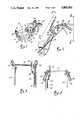
- FIG. 2is a side view showing the handle and control portion of a lawn mower illustrated in FIG. 1;
- FIG. 3is a view taken along lines 3--3 of FIG. 2;
- FIG. 4is a view taken along lines 4--4 of FIG. 2;
- FIG. 5is a perspective exploded view of the handle and control portion shown in FIG. 2;
- FIG. 6schematically illustrates the interaction between the lawn mower controls and the ignition system.
- the power lawn mower 10 illustrated in FIG. 1includes a drive assembly 11 and a cutter assembly 12.
- the drive assembly 11includes a frame 13 for supporting a conventional gasoline engine 14.
- a pair of rear drive wheels 16are mounted on frame 13 and generally below the engine 14. Power is transferred from the engine 14 to the rear wheels 16 by means of a belt drive assembly 18 which is conventional and, accordingly, will not be described in detail.
- the drive 18includes a drive pulley 20 mounted on jack shaft 22 extending from a transmission 24 mounted on frame 13 behind engine 14.
- the engine drive shaft(not shown) is coupled to the transmission 24 in any suitable manner, such as by a belt drive (not shown) and a clutch (not shown).
- the cutter assembly 12is also conventional and will not be disclosed in detail for the sake of brevity.
- the cutter assembly 12includes a cutter deck 26 suitably mounted at the front of frame 13 by brackets 28.
- Mounted below the cutter deck 26is one or more cutter blades (not shown) which rotate in a horizontal plane on vertical shafts (not shown) which are coupled to the engine 14 by a third belt drive (not shown) but which is mounted beneath a cover 29.
- the cutter blade or blades and the associated belt driveare conventional as are the transmission 24 and the rear wheel drive. Accordingly, these parts will not be shown in detail for the sake of brevity.
- a second pair of wheels 30are mounted at the front of the cutter deck 26 by means of caster assemblies 31 which permit the mower to be steered by a handle assembly 32 mounted at the rear of frame 13.
- the handle assembly 32consists of a pair of handle members 34 and 35 and a cross member 37 which is secured adjacent the upper end of handle members 34 and 35 to hold the same in a spaced apart parallel relation.
- Each handle memberis also fixed to the frame 13 by bolts 39 and extend upwardly and rearwardly therefrom and each has a downward curve at its remote end for receiving a hand grip member 40. It will be appreciated that the operator controls the motion of the mower through the agency of the hand grips 40.
- the blade clutch assemblyincludes a blade clutch lever 46 pivotally mounted adjacent one end by means of a bolt 50 on a bracket 48 extending integrally forward from handle member 35.
- a bolt 50extends through aligned openings adjacent one end of the blade clutch lever 46 and in the bracket 48.
- An elongate blade clutch rod 52is bent inwardly at one end 53 for being received in a second opening which is in the other end of the blade clutch lever 46.
- Affixed to blade clutch lever 46 and extending from one side thereofis a generally L-shaped grip lever 55.
- the other end of the blade clutch rod 52is coupled to a blade clutch linkage (not shown) which is operable to move an idler pulley (not shown) into and out of engagement with the blade clutch belt drive (not shown) so that pivotal movement of the grip lever 55 in one direction will cause engagement of the blade clutch (not shown) whereby the cutter blades (not shown) will be rotated while pivotal movement of the grip lever 55 in the opposite direction will disengage the blade clutch (not shown) so that rotation of the cutter blade will cease.
- a blade clutch linkage(not shown) which is operable to move an idler pulley (not shown) into and out of engagement with the blade clutch belt drive (not shown) so that pivotal movement of the grip lever 55 in one direction will cause engagement of the blade clutch (not shown) whereby the cutter blades (not shown) will be rotated while pivotal movement of the grip lever 55 in the opposite direction will disengage the blade clutch (not shown) so that rotation of the cutter blade will cease.
- the shift lever assembly 44includes a shaped shift lever 58 coupled at its lower end to the rear wheel transmission drive assembly (not shown).
- the upper end of the shift lever 58is coupled to a shift lever extension 60 having a hand grip 61 at its upper end.
- movement of the shift lever 58 in one directionwill shift the transmission from neutral to couple the engine 14 to the rear wheels 16.
- movement of the shift lever 58 in the opposite directionwill return the transmission to neutral thereby disengaging the rear wheels 16 from the engine 14.
- the lawn mower described aboveis conventional and accordingly has not been described in detail nor has all of the conventional details been illustrated.
- conventional lawn mowersalso include safety interlocks which cause the engine to be stopped unless either the drive wheels and cutter blade are disengaged from the engine or a safety interlock lever be gripped by the operator.
- the instant inventioncomprises a specific safety interlock 62 which will now be described.
- the safety interlock assembly 62in accordance with the preferred embodiment of the invention includes a pair of safety interlock levers 64 and 65 mounted at the opposite ends of a pivot control rod 67 which extends through the handle cross member 37. Suitable bushings 68 support the pivot control rod 67 for rotation about its axis within member 37.
- Each lever 64 and 65has an angled rod 66 secured at one end to a member 71 which is fixed to the end of control rod 67 by set screw 72.
- each rod 66has an outward bend at its end adjacent cross member 70 and an inward bend at its opposite end which engages the hand grip 73 as shown in FIGS. 3 and 5.
- a hand grip 73may be fixed to the free end of each rod 66 and extends longitudinally therefrom.
- the hand grips 73may comprise relatively flat bars which may be pivoted downwardly from a remote position shown in FIG. 2 to position adjacent the grips 40 as shown in FIGS. 3 and 4.
- the rods 66are shaped as shown in FIGS. 2 and 4 such that when they are pivoted downwardly the hand grips 73 move adjacent the lower outside portion of hand grips 40.
- a small spring 74is coupled to one interlock lever 65 and a bracket 75 on handle 35.
- the spring 74is placed under tension.
- the spring 74urges the safety interlock levers 64 and 65 from their positions shown in FIG. 4 wherein they are adjacent the hand grips 40 to their position shown in FIG. 2 wherein they are displaced upward from the hand grips 40.
- the operatorreleases the safety interlock levers 64 and 65, they will move from their position shown in FIG. 4 to their position shown in FIG. 2.
- FIG. 6shows the lawn mower safety control system to include interlock switches 76 and 78 connected in parallel between the electrical ground 83 and the mower engine ignition system 84.
- a third switch 85is connected in series with switches 76 and 78.
- Interlock switch 76is mechanically coupled to the shift lever 58
- the interlock switch 78is mechanically coupled to the blade clutch lever 46
- the interlock switch 85is coupled to the safety interlock lever 64, 65 or both.
- the levers 46 and 58 and the interlock levers 64 and 65engage the switches 76, 78 and 85 in a conventional manner well known in the art.
- lever 46is connected to one end of the blade clutch rod 52 (FIG. 5).
- the other end of the clutch rod 53is connected to a lever 90 which is also connected to the switch 78 in a conventional manner (not shown).
- the rod 52is also coupled to an eye bolt 91 which in turn is coupled to the mowers clutch idler arm (not shown).
- the shift lever 58is coupled to a conventional ignition switch 76 in a manner well known in the art.
- the interlock switch 85is mounted on the lower end of the bracket 75 as shown in FIGS. 2 and 5.
- the end of rod 66 of interlock lever 65pivots adjacent the upper end of bracket 75 and is coupled to switch 85 by a link 96 schematically illustrated in FIG. 6.
- switches 76 and 78are closed when the shift lever 58 and the blade clutch lever 46 are in their engaged positions and switches 76 and 78 are open when the shift lever 58 and the blade clutch lever 46 are in their neutral positions.
- Switch 85is in its closed position when the safety interlock levers 64 and 65 are released so that they are remote from the hand grips 40 and switch 85 is open when the safety interlock levers are held by the operator in engagement with the hand grips 40. It can thus be seen that for the engine ignition system 82 to be energized, either both the shift lever 58 and the blade clutch lever 46 must be in their neutral positions, or the operator must retain the safety interlock hand grips 73 in engagement with the hand grips 40. This prevents the operator from leaving the mower unattended while the cutter blades or the drive wheels 16 are being driven.
- Interlock lever 65pivots adjacent the upper end of bracket 75 and is coupled to switch 85 by a link 96 schematically illustrated in FIG. 6.
- a conventional brake hand grip 97is pivotally mounted on handle member 35 and is connected by a control rod 98 to a brake (not shown) mounted on one of the mower's drive wheels 16.
- the brakeis conventional and forms no part of the invention and, therefore, will not be discussed for the sake of brevity.
- a throttle control 99is mounted on handle 34 and is connected to the engine throttle (not shown) by a cable 100 in a conventional manner.
- the configuration of the safety interlock levers 64 and 65permit the operator to grasp both hand grips 73 and 40 simultaneously with his fingertips as though they were a single member. As a result, the operator is relieved from tension and hand irritation which were common with safety interlock systems of prior art lawn mowers. In fact, the operator will be virtually unaware that he is gripping the safety interlock levers because the hand grips 62 and 40 will feel like a single member.
- interlock levers 64 and 65are shown to be coupled to each other by the pivot control rod 67, they may be pivoted individually with each being mechanically coupled to the switch 85.
Landscapes
- Life Sciences & Earth Sciences (AREA)
- Environmental Sciences (AREA)
- Harvester Elements (AREA)
Abstract
Description
Claims (5)
Priority Applications (1)
| Application Number | Priority Date | Filing Date | Title |
|---|---|---|---|
| US07/224,925US4885903A (en) | 1988-07-27 | 1988-07-27 | Safety interlock for lawn mowers |
Applications Claiming Priority (1)
| Application Number | Priority Date | Filing Date | Title |
|---|---|---|---|
| US07/224,925US4885903A (en) | 1988-07-27 | 1988-07-27 | Safety interlock for lawn mowers |
Publications (1)
| Publication Number | Publication Date |
|---|---|
| US4885903Atrue US4885903A (en) | 1989-12-12 |
Family
ID=22842798
Family Applications (1)
| Application Number | Title | Priority Date | Filing Date |
|---|---|---|---|
| US07/224,925Expired - Fee RelatedUS4885903A (en) | 1988-07-27 | 1988-07-27 | Safety interlock for lawn mowers |
Country Status (1)
| Country | Link |
|---|---|
| US (1) | US4885903A (en) |
Cited By (22)
| Publication number | Priority date | Publication date | Assignee | Title |
|---|---|---|---|---|
| EP0448992A1 (en)* | 1990-03-12 | 1991-10-02 | Deere & Company | Safety mechanism for a work implement, especially a lawn mower |
| US5138824A (en)* | 1990-05-25 | 1992-08-18 | Kubota Corporation | Safety system for a lawn mower |
| US5146735A (en)* | 1990-06-29 | 1992-09-15 | Fuqua Industries, Inc. | Lawn mower drive and control systems |
| US5215056A (en)* | 1991-11-27 | 1993-06-01 | Kubota Corporation | Engine speed control system for a working vehicle |
| US5343678A (en)* | 1993-02-04 | 1994-09-06 | Ransomes, Inc. | Lawn mower control device |
| US5415059A (en)* | 1993-08-11 | 1995-05-16 | Ransomes American Corporation | Turf machine lockable brake mechanism |
| US5488818A (en)* | 1993-06-28 | 1996-02-06 | The Actava Group Inc. | Lawn mower having improved trim feature |
| US5507138A (en)* | 1994-12-16 | 1996-04-16 | Wright Manufacturing Inc. | Power mower with riding platform for supporting standing-operator |
| US5511367A (en)* | 1993-06-28 | 1996-04-30 | The Actava Group, Inc. | Lawn mower having additinal improved trim featuure |
| US5809755A (en)* | 1994-12-16 | 1998-09-22 | Wright Manufacturing, Inc. | Power mower with riding platform for supporting standing operator |
| US5895338A (en)* | 1997-11-12 | 1999-04-20 | Kohler Co. | Engine braking system using alternator stator windings |
| US5984031A (en)* | 1997-03-28 | 1999-11-16 | Wright Mfg., Inc. | Power mower with riding platform for supporting standing operator during operation |
| US6405515B1 (en) | 1994-12-16 | 2002-06-18 | Wright Manufacturing, Inc. | Power mower with riding platform for supporting standing-operator |
| US6516779B2 (en)* | 2000-01-18 | 2003-02-11 | Honda Giken Kogyo Kabushiki Kaisha | Throttle adjusting apparatus for working machine |
| US6557331B2 (en)* | 2001-06-27 | 2003-05-06 | Exmark Manufacturing Company, Inc. | Operator control system for self-propelled vehicles |
| US6668529B2 (en)* | 2001-06-27 | 2003-12-30 | Emark Manufacturing Company, Incorporated | Operator control system for self-propelled vehicles |
| US20090133022A1 (en)* | 2007-11-15 | 2009-05-21 | Karim Faraydon O | Multiprocessing apparatus, system and method |
| US20090223475A1 (en)* | 2008-03-10 | 2009-09-10 | Grant Thomas Wilson | Implement With Two Hand Interlock |
| EP2805597A1 (en)* | 2013-05-24 | 2014-11-26 | Honda Motor Co., Ltd. | Control devices, systems, and methods for self-propelled machinery |
| US20160037719A1 (en)* | 2013-01-25 | 2016-02-11 | Suzhou Cleva Electric Appliance Co., Ltd. | Operating control mechanism for garden tool |
| US20200245555A1 (en)* | 2019-01-31 | 2020-08-06 | Techtronic Cordless Gp | Power tool having a variable height or speed |
| US12439849B2 (en) | 2023-09-08 | 2025-10-14 | Techtronic Cordless Gp | Power tool having a variable height or speed |
Citations (6)
| Publication number | Priority date | Publication date | Assignee | Title |
|---|---|---|---|---|
| US3942604A (en)* | 1974-08-13 | 1976-03-09 | Indak Manufacturing Corporation | Safety system for lawn mowers or other vehicles |
| US3969875A (en)* | 1975-04-18 | 1976-07-20 | Mtd Products Inc. | Safety grounding circuits |
| US4062135A (en)* | 1976-10-04 | 1977-12-13 | Deere & Company | Safe operation control for a snowblower |
| US4476643A (en)* | 1983-03-08 | 1984-10-16 | Mtd Products Limited | Hand control system for motorized implements |
| US4667459A (en)* | 1985-03-14 | 1987-05-26 | Roper Corporation | Two action control for power mowers |
| US4704847A (en)* | 1985-12-09 | 1987-11-10 | Western International, Inc. | Control mechanism for walk-behind mower |
- 1988
- 1988-07-27USUS07/224,925patent/US4885903A/ennot_activeExpired - Fee Related
Patent Citations (6)
| Publication number | Priority date | Publication date | Assignee | Title |
|---|---|---|---|---|
| US3942604A (en)* | 1974-08-13 | 1976-03-09 | Indak Manufacturing Corporation | Safety system for lawn mowers or other vehicles |
| US3969875A (en)* | 1975-04-18 | 1976-07-20 | Mtd Products Inc. | Safety grounding circuits |
| US4062135A (en)* | 1976-10-04 | 1977-12-13 | Deere & Company | Safe operation control for a snowblower |
| US4476643A (en)* | 1983-03-08 | 1984-10-16 | Mtd Products Limited | Hand control system for motorized implements |
| US4667459A (en)* | 1985-03-14 | 1987-05-26 | Roper Corporation | Two action control for power mowers |
| US4704847A (en)* | 1985-12-09 | 1987-11-10 | Western International, Inc. | Control mechanism for walk-behind mower |
Cited By (50)
| Publication number | Priority date | Publication date | Assignee | Title |
|---|---|---|---|---|
| EP0448992A1 (en)* | 1990-03-12 | 1991-10-02 | Deere & Company | Safety mechanism for a work implement, especially a lawn mower |
| US5138824A (en)* | 1990-05-25 | 1992-08-18 | Kubota Corporation | Safety system for a lawn mower |
| US5146735A (en)* | 1990-06-29 | 1992-09-15 | Fuqua Industries, Inc. | Lawn mower drive and control systems |
| US5215056A (en)* | 1991-11-27 | 1993-06-01 | Kubota Corporation | Engine speed control system for a working vehicle |
| US5343678A (en)* | 1993-02-04 | 1994-09-06 | Ransomes, Inc. | Lawn mower control device |
| US5511367A (en)* | 1993-06-28 | 1996-04-30 | The Actava Group, Inc. | Lawn mower having additinal improved trim featuure |
| US5488818A (en)* | 1993-06-28 | 1996-02-06 | The Actava Group Inc. | Lawn mower having improved trim feature |
| US5415059A (en)* | 1993-08-11 | 1995-05-16 | Ransomes American Corporation | Turf machine lockable brake mechanism |
| US6390225B2 (en) | 1994-12-16 | 2002-05-21 | Wright Manufacturing, Inc. | Power mower with riding platform for supporting standing operator during operation |
| US5600944A (en)* | 1994-12-16 | 1997-02-11 | Wright Manufacturing, Inc. | Power mower with riding platform for supporting standing-operator |
| US5765347A (en)* | 1994-12-16 | 1998-06-16 | Wright Manufacturing, Inc. | Power mower with riding platform for supporting stand-operator |
| US5809755A (en)* | 1994-12-16 | 1998-09-22 | Wright Manufacturing, Inc. | Power mower with riding platform for supporting standing operator |
| US6912831B2 (en) | 1994-12-16 | 2005-07-05 | Wright Manufacturing, Inc. | Power mower with pump lock-out system |
| US5964082A (en)* | 1994-12-16 | 1999-10-12 | Wright Manufacturing, Inc. | Power mower with riding platform for supporting standing-operator |
| US6862872B2 (en) | 1994-12-16 | 2005-03-08 | Wright Manufacturing, Inc. | Power mower with riding platform for supporting standing-operator |
| US6059055A (en)* | 1994-12-16 | 2000-05-09 | Wright Manufacturing, Inc. | Power mower with riding platform for supporting standing operator |
| US6085504A (en)* | 1994-12-16 | 2000-07-11 | Wright Manufacturing, Inc. | Power mower with riding platform for supporting standing-operator |
| US6094897A (en)* | 1994-12-16 | 2000-08-01 | Wright Manufacturing, Inc. | Power mower with riding platform for supporting standing operator |
| US20040103629A1 (en)* | 1994-12-16 | 2004-06-03 | Velke James D. | Power mower with pump lock-out system |
| US6550563B2 (en) | 1994-12-16 | 2003-04-22 | Wright Manufacturing, Inc. | Power mower with riding platform for supporting standing operator during operation |
| US6189304B1 (en) | 1994-12-16 | 2001-02-20 | Wright Manufacturing, Inc. | Power mower with riding platform for supporting standing operator |
| US6189305B1 (en) | 1994-12-16 | 2001-02-20 | Wright Manufacturing, Inc. | Power mower with riding platform for supporting standing-operator |
| US6276486B1 (en) | 1994-12-16 | 2001-08-21 | Wright Manufacturing Inc. | Power mower with riding platform for supporting standing operator during operation |
| US20040055267A1 (en)* | 1994-12-16 | 2004-03-25 | Wright Manufacturing, Inc. | Power mower with riding platform for supporting standing-operator |
| US6327839B1 (en) | 1994-12-16 | 2001-12-11 | Wright Manufacturing, Inc. | Power mower with riding platform for supporting standing operator |
| US5507138A (en)* | 1994-12-16 | 1996-04-16 | Wright Manufacturing Inc. | Power mower with riding platform for supporting standing-operator |
| US6405515B1 (en) | 1994-12-16 | 2002-06-18 | Wright Manufacturing, Inc. | Power mower with riding platform for supporting standing-operator |
| US6688090B2 (en) | 1994-12-16 | 2004-02-10 | Wright Manufacturing, Inc. | Power mower with riding platform for supporting standing operator |
| US6516596B2 (en) | 1994-12-16 | 2003-02-11 | Wright Manufacturing, Inc. | Power mower with riding platform for supporting standing operator |
| US6625965B2 (en) | 1994-12-16 | 2003-09-30 | Wright Manufacturing, Inc. | Power mower with riding platform for supporting standing-operator |
| US6182429B1 (en) | 1997-03-28 | 2001-02-06 | Wright Manufacturing, Inc. | System for enabling grass catcher to be attached to self-propelled power mower |
| US6138446A (en)* | 1997-03-28 | 2000-10-31 | Wright Manufacturing, Inc. | Power mower with riding platform for supporting standing operator during operation |
| US6640526B2 (en) | 1997-03-28 | 2003-11-04 | Wright Manufacturing, Inc. | Control assembly for steering lawn mower |
| US5984031A (en)* | 1997-03-28 | 1999-11-16 | Wright Mfg., Inc. | Power mower with riding platform for supporting standing operator during operation |
| US6415587B1 (en) | 1997-03-28 | 2002-07-09 | Wright Manufacturing, Inc. | System for enabling grass catcher to be attached to self-propelled power mower |
| US6301865B1 (en) | 1997-03-28 | 2001-10-16 | Wright Manufacturing, Inc. | System for enabling grass catcher to be attached to self-propelled power mower |
| US5895338A (en)* | 1997-11-12 | 1999-04-20 | Kohler Co. | Engine braking system using alternator stator windings |
| US6516779B2 (en)* | 2000-01-18 | 2003-02-11 | Honda Giken Kogyo Kabushiki Kaisha | Throttle adjusting apparatus for working machine |
| US6668529B2 (en)* | 2001-06-27 | 2003-12-30 | Emark Manufacturing Company, Incorporated | Operator control system for self-propelled vehicles |
| US6557331B2 (en)* | 2001-06-27 | 2003-05-06 | Exmark Manufacturing Company, Inc. | Operator control system for self-propelled vehicles |
| US20030192295A1 (en)* | 2001-06-27 | 2003-10-16 | Exmark Manufacturing Company, Incorporated | Operator control system for self-propelled vehicles |
| US6951092B2 (en)* | 2001-06-27 | 2005-10-04 | Exmark Manufacturing Company, Incorporated | Operator control system for self-propelled vehicles |
| US20090133022A1 (en)* | 2007-11-15 | 2009-05-21 | Karim Faraydon O | Multiprocessing apparatus, system and method |
| US20090223475A1 (en)* | 2008-03-10 | 2009-09-10 | Grant Thomas Wilson | Implement With Two Hand Interlock |
| US20160037719A1 (en)* | 2013-01-25 | 2016-02-11 | Suzhou Cleva Electric Appliance Co., Ltd. | Operating control mechanism for garden tool |
| US9681604B2 (en)* | 2013-01-25 | 2017-06-20 | Suzhou Cleva Electric Appliance Co., Ltd. | Operating control mechanism for garden tool |
| EP2805597A1 (en)* | 2013-05-24 | 2014-11-26 | Honda Motor Co., Ltd. | Control devices, systems, and methods for self-propelled machinery |
| US9696749B2 (en) | 2013-05-24 | 2017-07-04 | Honda Motor Co., Ltd. | Control devices, systems, and methods for self-propelled machinery |
| US20200245555A1 (en)* | 2019-01-31 | 2020-08-06 | Techtronic Cordless Gp | Power tool having a variable height or speed |
| US12439849B2 (en) | 2023-09-08 | 2025-10-14 | Techtronic Cordless Gp | Power tool having a variable height or speed |
Similar Documents
| Publication | Publication Date | Title |
|---|---|---|
| US4885903A (en) | Safety interlock for lawn mowers | |
| US4476643A (en) | Hand control system for motorized implements | |
| US5146735A (en) | Lawn mower drive and control systems | |
| US6105348A (en) | Safety cut-off system for use in walk-behind power tool | |
| US5042238A (en) | Riding lawn mower | |
| US4255879A (en) | Snow blower dead man control | |
| CA2112057C (en) | Mower deck height adjustment mechanism | |
| US5247784A (en) | Transmission system capable of driving right and left drive wheels at different speeds | |
| US4396067A (en) | Tiller with rotatable tines and guiding handle | |
| US6341479B1 (en) | Hydrostatic drive walk-behind lawn mower | |
| US5297379A (en) | Walk-behind lawn mower with front wheel steering | |
| JPH0595702A (en) | Riding type lawn mower | |
| US4531347A (en) | Lawn mower with wheel drive | |
| US5651241A (en) | Walk-behind mower controls with dual function control bracket | |
| US4493180A (en) | Lawn mower dead man control | |
| US6199354B1 (en) | Foot-operated parking brake for walk-behind power tool | |
| US4747256A (en) | Lever mounting structure for lawn mower | |
| US4279179A (en) | Ignition system control | |
| US4244427A (en) | Tiller with rotatable tines and guiding handle | |
| US5020250A (en) | Powered snowplow | |
| US4146105A (en) | Lawn mower | |
| US4760687A (en) | Mower deck height and clutch control | |
| US6237311B1 (en) | Reverse mowing prevention device | |
| US4514967A (en) | Bridge support for securing sulky to walk-behind mower | |
| US4450927A (en) | Apparatus for controlling agricultural tractor |
Legal Events
| Date | Code | Title | Description |
|---|---|---|---|
| AS | Assignment | Owner name:SCAG POWER EQUIPMENT, INC. A CORP. OF WISCONSIN Free format text:ASSIGNMENT OF ASSIGNORS INTEREST.;ASSIGNOR:SCAG, DANE T.;REEL/FRAME:005697/0955 Effective date:19910506 | |
| AS | Assignment | Owner name:NORWEST BANK WISCONSIN EAST CENTRAL A STATE BAN Free format text:SECURITY INTEREST;ASSIGNOR:SCAG POWER EQUIPMENT, INC., A CORPORATION OF WI;REEL/FRAME:005751/0085 Effective date:19910513 Owner name:NORWEST BANK WISCONSIN EAST CENTRAL (F/K/A FIRST I Free format text:SECURITY INTEREST;ASSIGNOR:SCAG POWER EQUIPMENT, INC., A CORPORATION OF WI;REEL/FRAME:005751/0103 Effective date:19910513 | |
| CC | Certificate of correction | ||
| REMI | Maintenance fee reminder mailed | ||
| LAPS | Lapse for failure to pay maintenance fees | ||
| FP | Lapsed due to failure to pay maintenance fee | Effective date:19931212 | |
| AS | Assignment | Owner name:NORWEST BANK WISCONSIN, NATIONAL ASSOCIATION F/K/A Free format text:RELEASE;ASSIGNOR:SCAG POWER EQUIPMENT, INC., A WISCONSIN CORP.;REEL/FRAME:007526/0338 Effective date:19910513 | |
| AS | Assignment | Owner name:PNC BANK, NATIONAL ASSOCIATION, PENNSYLVANIA Free format text:SECURITY AGREEMENT;ASSIGNOR:METALCRAFT OF MAYVILLE, INC.;REEL/FRAME:025238/0486 Effective date:20101006 | |
| STCH | Information on status: patent discontinuation | Free format text:PATENT EXPIRED DUE TO NONPAYMENT OF MAINTENANCE FEES UNDER 37 CFR 1.362 |