US4885663A - Fiber optic light emitting panel and method of making same - Google Patents
Fiber optic light emitting panel and method of making sameDownload PDFInfo
- Publication number
- US4885663A US4885663AUS07/171,844US17184488AUS4885663AUS 4885663 AUS4885663 AUS 4885663AUS 17184488 AUS17184488 AUS 17184488AUS 4885663 AUS4885663 AUS 4885663A
- Authority
- US
- United States
- Prior art keywords
- emitter surface
- light
- optical fibers
- panel
- bends
- Prior art date
- Legal status (The legal status is an assumption and is not a legal conclusion. Google has not performed a legal analysis and makes no representation as to the accuracy of the status listed.)
- Expired - Lifetime
Links
- 238000004519manufacturing processMethods0.000titleclaimsabstractdescription8
- 239000000835fiberSubstances0.000titleabstractdescription38
- 239000004973liquid crystal related substanceSubstances0.000claimsabstractdescription20
- 239000013307optical fiberSubstances0.000claimsdescription125
- 238000000576coating methodMethods0.000claimsdescription43
- 239000011248coating agentSubstances0.000claimsdescription42
- 238000000034methodMethods0.000claimsdescription25
- 239000000463materialSubstances0.000claimsdescription12
- 238000009941weavingMethods0.000claimsdescription10
- 230000007423decreaseEffects0.000claimsdescription6
- 229920000742CottonPolymers0.000claimsdescription4
- 238000002347injectionMethods0.000claimsdescription3
- 239000007924injectionSubstances0.000claimsdescription3
- 239000002985plastic filmSubstances0.000claimsdescription3
- 229920006255plastic filmPolymers0.000claimsdescription3
- 230000008569processEffects0.000claimsdescription3
- 238000010030laminatingMethods0.000claims1
- 238000005498polishingMethods0.000claims1
- 238000007493shaping processMethods0.000claims1
- 238000007666vacuum formingMethods0.000claims1
- 230000008859changeEffects0.000abstractdescription10
- 239000000382optic materialSubstances0.000abstractdescription8
- 239000011162core materialSubstances0.000description9
- 230000003287optical effectEffects0.000description8
- 239000004593EpoxySubstances0.000description4
- 239000004033plasticSubstances0.000description4
- NIXOWILDQLNWCW-UHFFFAOYSA-Nacrylic acid groupChemical groupC(C=C)(=O)ONIXOWILDQLNWCW-UHFFFAOYSA-N0.000description3
- 238000005286illuminationMethods0.000description3
- 239000000853adhesiveSubstances0.000description2
- 230000001070adhesive effectEffects0.000description2
- 239000002390adhesive tapeSubstances0.000description2
- 230000004075alterationEffects0.000description2
- 238000005452bendingMethods0.000description2
- 230000008901benefitEffects0.000description2
- 230000005540biological transmissionEffects0.000description2
- 238000005266castingMethods0.000description2
- 238000009792diffusion processMethods0.000description2
- 239000011521glassSubstances0.000description2
- 238000012986modificationMethods0.000description2
- 230000004048modificationEffects0.000description2
- 238000006748scratchingMethods0.000description2
- 230000002393scratching effectEffects0.000description2
- 229920001187thermosetting polymerPolymers0.000description2
- 239000012780transparent materialSubstances0.000description2
- 238000010521absorption reactionMethods0.000description1
- 230000002411adverseEffects0.000description1
- 239000004568cementSubstances0.000description1
- 230000008021depositionEffects0.000description1
- 230000005684electric fieldEffects0.000description1
- 229920006334epoxy coatingPolymers0.000description1
- 239000000499gelSubstances0.000description1
- 238000001746injection mouldingMethods0.000description1
- 238000007689inspectionMethods0.000description1
- 239000003921oilSubstances0.000description1
- 230000010287polarizationEffects0.000description1
- 229920001296polysiloxanePolymers0.000description1
- 238000002310reflectometryMethods0.000description1
- 229920005989resinPolymers0.000description1
- 239000011347resinSubstances0.000description1
- 239000007787solidSubstances0.000description1
- 238000005507sprayingMethods0.000description1
- 239000000126substanceSubstances0.000description1
Images


Classifications
- G—PHYSICS
- G02—OPTICS
- G02B—OPTICAL ELEMENTS, SYSTEMS OR APPARATUS
- G02B6/00—Light guides; Structural details of arrangements comprising light guides and other optical elements, e.g. couplings
- G02B6/0001—Light guides; Structural details of arrangements comprising light guides and other optical elements, e.g. couplings specially adapted for lighting devices or systems
- G02B6/0005—Light guides; Structural details of arrangements comprising light guides and other optical elements, e.g. couplings specially adapted for lighting devices or systems the light guides being of the fibre type
- G02B6/001—Light guides; Structural details of arrangements comprising light guides and other optical elements, e.g. couplings specially adapted for lighting devices or systems the light guides being of the fibre type the light being emitted along at least a portion of the lateral surface of the fibre
- D—TEXTILES; PAPER
- D03—WEAVING
- D03D—WOVEN FABRICS; METHODS OF WEAVING; LOOMS
- D03D15/00—Woven fabrics characterised by the material, structure or properties of the fibres, filaments, yarns, threads or other warp or weft elements used
- D03D15/20—Woven fabrics characterised by the material, structure or properties of the fibres, filaments, yarns, threads or other warp or weft elements used characterised by the material of the fibres or filaments constituting the yarns or threads
- D03D15/208—Woven fabrics characterised by the material, structure or properties of the fibres, filaments, yarns, threads or other warp or weft elements used characterised by the material of the fibres or filaments constituting the yarns or threads cellulose-based
- D03D15/217—Woven fabrics characterised by the material, structure or properties of the fibres, filaments, yarns, threads or other warp or weft elements used characterised by the material of the fibres or filaments constituting the yarns or threads cellulose-based natural from plants, e.g. cotton
- D—TEXTILES; PAPER
- D03—WEAVING
- D03D—WOVEN FABRICS; METHODS OF WEAVING; LOOMS
- D03D15/00—Woven fabrics characterised by the material, structure or properties of the fibres, filaments, yarns, threads or other warp or weft elements used
- D03D15/50—Woven fabrics characterised by the material, structure or properties of the fibres, filaments, yarns, threads or other warp or weft elements used characterised by the properties of the yarns or threads
- D03D15/547—Woven fabrics characterised by the material, structure or properties of the fibres, filaments, yarns, threads or other warp or weft elements used characterised by the properties of the yarns or threads with optical functions other than colour, e.g. comprising light-emitting fibres
- D—TEXTILES; PAPER
- D03—WEAVING
- D03D—WOVEN FABRICS; METHODS OF WEAVING; LOOMS
- D03D15/00—Woven fabrics characterised by the material, structure or properties of the fibres, filaments, yarns, threads or other warp or weft elements used
- D03D15/60—Woven fabrics characterised by the material, structure or properties of the fibres, filaments, yarns, threads or other warp or weft elements used characterised by the warp or weft elements other than yarns or threads
- D03D15/62—Cords or ropes
- D—TEXTILES; PAPER
- D10—INDEXING SCHEME ASSOCIATED WITH SUBLASSES OF SECTION D, RELATING TO TEXTILES
- D10B—INDEXING SCHEME ASSOCIATED WITH SUBLASSES OF SECTION D, RELATING TO TEXTILES
- D10B2401/00—Physical properties
- D10B2401/20—Physical properties optical
- F—MECHANICAL ENGINEERING; LIGHTING; HEATING; WEAPONS; BLASTING
- F21—LIGHTING
- F21V—FUNCTIONAL FEATURES OR DETAILS OF LIGHTING DEVICES OR SYSTEMS THEREOF; STRUCTURAL COMBINATIONS OF LIGHTING DEVICES WITH OTHER ARTICLES, NOT OTHERWISE PROVIDED FOR
- F21V2200/00—Use of light guides, e.g. fibre optic devices, in lighting devices or systems
- F21V2200/10—Use of light guides, e.g. fibre optic devices, in lighting devices or systems of light guides of the optical fibres type
- F21V2200/15—Use of light guides, e.g. fibre optic devices, in lighting devices or systems of light guides of the optical fibres type the light being emitted along at least a portion of the outer surface of the guide
Definitions
- This inventionrelates generally as indicated to a fiber optic light emitting panel and method of making same, and more particularly to a light emitting panel including an emitter surface in which optical fibers are woven into a sheet or mat and coated with a material having a refractive index that will cause a change in the attenuation of the optical fibers in the emitter surface to increase the optical efficiency of the panel.
- One of the primary advantages of constructing a light emitting panel utilizing such optical fibersis that the light source can be located remote from the panel for ease of changeability. Also, because the light source need not be incorporated in the panel itself, the panel can be made quite thin and of almost any size and shape, making it especially suitable for use in the back lighting of liquid crystal materials as well as signs and control panels generally.
- Another objectis to provide such a light emitting panel and method of making same in which the light output can be made relatively uniform over substantially the entire light emitting surface.
- Still another objectis to provide such a light emitting panel which emits polarized light with a maximum intensity on planes substantially normal to the emitter surface.
- Yet another objectis to provide such a light emitting panel which produces a higher light output.
- Still another objectis to provide such a light emitting panel and method of making same by which multiple layers of fiber optic material are disposed in such a way as to produce a higher light output and minimize the thickness of the panel.
- a further objectis to laminate such a fiber optical panel to a liquid crystal or other device to provide back lighting therefor.
- a light emitting panelthat has one or more layers of woven fiber optic material that are coated with a coating that changes the attenuation of the fibers in the emitter surface to increase the amount of light emitted therefrom.
- An epoxy or thermosetting plastic or cementmay be used as the coating, which also permits the top surface of the emitting surface to be shaped to shift the planes of maximum intensity of light to a plane that fits a particular application. Also, by changing the optical clarity of the coating, one can change the amount of light diffusion that takes place.
- a reflective surfaceis provided on the back and sides of the panel to reflect light back into the panel.
- both ends of the woven fiber optic materialmay be formed into light cables, preferably only one end is thus formed, and the other end is desirably cut and polished and a reflective surface is provided on the cut end to reflect light at the cut end back into the panel.
- a lenticular or prismatic filmmay be provided on the front of the emitter surface to shift the angular emission of light from the surface so the emitted light is substantially perpendicular to the plane of the emitter surface.
- the optical fiber coatingmay be used to laminate the emitter surface of such a light emitting panel to a liquid crystal and/or flexible pressure switch or other such device to provide back lighting therefor.
- the various component parts of the assemblymay be laminated together utilizing a suitable adhesive or a clear acrylic or plastic film vacuum formed around the assembly.
- the fiber optic layersmay be staggered on perpendicular planes to produce a higher light output and to decrease the overall thickness of the panel.
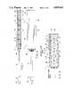
- FIG. 1is a schematic fragmentary longitudinal section through one form of fiber optic light emitting panel in accordance with this invention
- FIG. 2is a top plan view of the light emitting panel of FIG. 1;
- FIG. 3is an enlarged schematic fragmentary longitudinal section through a portion of the emitter surface of the light emitting panel of FIGS. 1 and 2;
- FIGS. 4A, 4B and 4Care schematic illustrations representing the light output of the panel of FIGS. 1 through 3 at different stages during fabrication;
- FIG. 5is an enlarged schematic longitudinal section through another form of fiber optic light emitting panel in accordance with this invention shown laminated to a liquid crystal;
- FIG. 6is an enlarged schematic longitudinal section through still another form of fiber optic light emitting panel in accordance with this invention.
- FIG. 7is an enlarged schematic end view of one form of optical fiber which may be used to make a fiber optic light emitting panel in accordance with the present invention consisting of a plurality of optical fiber strands twisted together to form a single optical fiber;
- FIGS. 8 and 9are enlarged schematic end views of two additional optical fiber configurations each consisting of a plurality of optical fibers of the type illustrated in FIG. 7 to form a multi-strand optical fiber cable;
- FIG. 10is a schematic side elevation view of another form of fiber optic light emitting panel in accordance with this invention including one or more loosely woven ribbon-type cable members at one end of the panel; and
- FIG. 11is a schematic top plan view of the light emitting panel of FIG. 10.
- FIGS. 1-3there is schematically shown one form of light emitting panel 1 in accordance with this invention including an emitter surface 2 made of one or more layers 3, 4 of fiber optic material 5.
- Each layer 3, 4may be woven into a sheet or mat in the manner disclosed, for example, in U.S. Pat. No. 4,234,907 granted to Maurice Daniel on Nov. 18, 1980, which is incorporated herein by reference.
- the fiber optic filaments 5are woven in only the warp direction and fill threads 6, 6' made, for example, of cotton fiber which acts as a diffuser, are woven in the weft direction.
- the weft threadsare the threads usually carried by the shuttle in weaving, whereas the warp threads extend lengthwise in the loom, crossed by the weft threads.
- Each optical fiber 5is made from one or more optical fiber strands 7 each including a light transmitting core portion of a suitable transparent material and an outer sheath of a second transparent material having a relatively lower index of refraction than the core material to prevent the escape of light along its length.
- the core materialcan be made of either glass or plastic or a multi-strand filament having the desired optical characteristics.
- the outer sheath materialis desirably equally transparent, but because the index of refraction of the sheath material is less than that of the core material, total reflection is obtained at the sheath-core interface, as well known in the art.
- the external surface of the optical fibersmay be disrupted as by scratching or otherwise causing mechanical, chemical or other deformation at discrete locations along their lengths.
- the amount of light emitted at these locationswill depend on the depth and frequency of such disruptions. If the optical fibers are deformed at decreasingly spaced intervals as the distance from the light source increases, there will be more uniform emission of light from the emitter surface when viewed from a distance. Also, such deformation may be achieved by bending the optical fibers 5 at a plurality of discrete locations along their lengths as best seen in FIG. 3 such that the angle of each bend 8 approximately exceeds the angle of internal reflection so that light will be emitted at each such bend.
- Each optical fiber 5may consist of a single optical fiber strand 7. However, preferably a plurality of such strands 7 are twisted together to form a multi-strand optical fiber 9 as schematically shown in FIG. 7 for use as such optical fibers 5.
- Making a fiber optic light emitting panel 1 utilizing multi-strand optical fibersmakes it much easier to bend the optical fibers to the extent necessary to cause light to be emitted from the optical fibers in the light emitting section 2 as desired.
- glass multi-strand fiberspermit the panel to be used to transmit infra-red and ultra-violet frequencies of light, which is not possible with single strand fibers. The ability to transmit infra-red and ultra-violet light is desirable in certain applications, such as when the panel is to be used as an ultra-violet epoxy curing light or as an infra-red heat source.
- a plurality of such multi-strand optical fibers 9may be wrapped around a plastic or fiber core 20 and/or coated with a suitable plastic material 21 to form multi-strand optical fiber cables 22 or 22' as schematically shown in FIGS. 8 and 9, respectively, for use as such optical fibers 5.
- the core 20 and/or coating 21may be used separately or combined as desired to help support the optical fibers under tensile-load, which is particularly advantageous where the optical fibers extend from one or both ends of the light emitting panel section for use as a light cable or light pipe for transmitting light from a remote light source as schematically shown in FIGS. 1 and 2.
- the core 20may be advantageously used as a back reflector or defuser for the light that is emitted from the emitter surface 2 of the light emitting panel 1 as described hereafter.
- the uniformity of illumination of the emitter surfacecan be varied by varying the shape of disruptions or bends and/or the spacing between the disruptions or bends on the fiber surface as by varying the pattern and tightness of the weave and by varying the proportion of optical fibers to other material in the weave.
- the illuminationcan, for example, be increased by making the disruptions closer together or by making the weave progressively tighter as the distance from the light source increases.
- fill threads 6 having different coefficients of frictionwill help to control the tightness of the weave, in that the higher the coefficient of friction, the tighter it is possible to weave the optical fibers.
- a plurality of fill threadsmay be used to provide more surface points for increased friction, and to reduce the thickness of each individual fill thread (and thus the thickness of the panel) while still achieving the same rigidity provided by a thicker fill thread.
- a double fill thread 6, 6'is preferred.
- Different colored fill threadsmay be used to vary the type or color of light being emitted from the optical fibers. Moreover, the more transparent the fill threads are, the more the emitted light will be permitted to pass through the fill threads.
- the optical fibers 5 at one or both ends of the emitter surface 2may be brought together to form a light cable which is used to transmit light from a remote light source to the emitter surface.
- one end 10 of the optical fibers 5is shown formed into such a light cable 11.
- a light cablemay be formed by loosely weaving the fill threads 6 or 6' at one or both ends of the light emitting section 2' of the panel 1' to act as a harness to produce a ribbon-like cable 13 as schematically shown in FIGS. 10 and 11.
- the loose weaveonly acts as a harness for the optical fibers 5 and does not cause the fibers to bend to the degree necessary to emit light in the cable section as does the tighter weave in the light emitting panel section 2'.
- a connector 12which serves as the interface between a light source 14 and the optical fiber ends of the cable, which are desirably polished and held by the connector 12 on a plane perpendicular to the principal optical axis of the light source.
- the light source 14may be of any suitable type including any of the types disclosed in applicant's co-pending application Ser. No. 125,323, filed Nov. 24, 1987, which is incorporated herein by reference. Furthermore, multiple light sources 14 and 14' may be used for a single light emitting panel 1', either by focusing the light from such multiple light sources onto the end of a single cable or by providing single panel with multiple cable ends 17, 17' each having an individual light source 14, 14' as schematically shown in FIG. 11. Also, if desired, the light source may be epoxied directly to the end of the fiber optic cable.
- the other ends 15 of the fiber optic filaments 5may also be formed into a cable and used to transmit light to the emitter surface from a remote light source if desired.
- the other ends 15are desirably cut and polished and a reflector 16 is desirably provided at such ends to reflect light at the other ends of the fibers back into the panel.
- the sides 23are desirably cut and polished and a reflector surface is desirably provided on such sides to reflect light at the sides back into the panel. This is particularly advantageous when the light emitting panel is used in certain back lighting applications where the emitter surface can readily be inserted or slipped in from one side for ease of assembly.
- a reflective surface 17may be vacuum deposited directly on the woven material or otherwise mounted to the back of the emitter surface 2 as further shown in FIGS. 1 and 3 to reflect light back through the emitter surface.
- the optical fibers 5 in the emitter surface 2are provided with a coating 18 (see FIG. 3) having a different refractive index than the core material of the optical fibers, such refractive index being such that the coating will cause a change in the attenuation of the light being emitted from the disruptions or bends in the optical fibers in the emitter surface 2.
- the coating 18may, for example, be oils, epoxy, gels, translucent plastic, adhesive tape or thermosetting resins and the like. Also silicone could be used for the coating to add flexibility to the panel.
- the coatingmay be applied by casting, spraying or injection molding the coating material around the optical fibers.
- the woven optical fibers 5 that make up the emitter surface 2can have coating 18 applied therefore before or after the weaving process. If the coating 18 is applied before weaving, the coating must be sufficiently ductile so as not to adversely affect the weaving process. Also, the coating is at least partially transparent in nature to allow for the passage of light.
- the coating 18 usedis a clear epoxy which changes the attenuation a predetermined amount.
- a lenticular or prismatic film 19is desirably mounted on the front of the emitter surface 2 to shift the angular emission of light.
- FIGS. 4A, B and Cschematically represent the light output of the light emitter surface 2 of FIGS. 1-3 at different stages during fabrication.
- the area under each curverepresents the total light output at that stage.
- the arrowsrepresent the average angular direction of the emitted light rays.
- the optical fibers 5are desirably wove such that their output progressively increases with the distance from the light source as schematically shown in FIG. 4A.
- the coating 18is applied to change the attenuation of the optical fibers 5 in the emitter surface 2 in order to produce a substantially uniform output and increase the overall output as schematically shown in FIG. 4B.
- the light raysmay be shifted so that they are substantially perpendicular to the plane of the emitter surface 2 a schematically shown in FIG. 4C.
- the light emitted from the emitter surface 2 of FIGS. 1 through 3will be polarized, which makes for a highly efficient back light for a liquid crystal display.
- a liquid crystal displayhas lower polarizer mounted between the liquid crystal and the back light.
- the lower polarizeris an optical device that transforms unpolarized or natural light into polarized light by selective transmission of polarized rays. This selective transmission allows only polarized light to pass and either absorbs or reflects the remaining light. Therefore, a back light in the form of a light emitting panel 1 of the type disclosed herein that emits polarized light will transmit a higher percentage of light through the liquid crystal than if an unpolarized back light of equal intensity were used.
- FIG. 5is a cross-sectional view of a liquid crystal display 24 laminated to an emitter surface 2' of fiber optic panel 1' generally of the type previously described, including a plurality of optical fibers 5 woven into one or more layers 3', 4' and a coating 18' surrounding the woven optical fibers 5' to change the attenuation of the optical fibers a predetermined amount.
- the coating 18'performs the additional function of acting as a bonding material between the front of the emitter surface 2' and the liquid crystal 24 as well as between the plural fiber optic layers 3', 4' and reflector surface 17'.
- the various component parts of the assemblymay be laminated together utilizing a suitable adhesive (including adhesive tape) or a clear acrylic or plastic film 30 vacuum formed around the assembly as schematically shown in FIG. 5.
- a defuser or prismatic film similar to the film 19 shown in FIGS. 1 and 3may be placed between the lower polarizer 25 of the liquid crystal 24 and the epoxy coating 18' to help smooth the light output if desired. Also, a retardation plate or phase shifter may be used in place of the lower polarizer 25 to rotate the plane of polarization of the light beam to a plane that can readily be transmitted through the liquid crystal.
- a suitable light sourcecan be mounted at a location remote from the emitter surface and liquid crystal where the light source can easily be replaced.
- a suitable light sourcereadily lends itself to using a light source having a relatively long life, such as a light emitting diode, to permit the assembly to function without having to change the light source for as many as 100,000 hours.
- filters of various typescan be placed between the light source and the cable end to reflect or absorb undesirable frequencies of light.
- An example where this would be advantageousis in a military aircraft cockpit display which cannot emit infrared light because of the use of an infrared sighting system.
- this type of light emitting panelcould be advantageously used as a back light is in the field of touch-screen liquid crystal displays. Since this type of back light does not produce any electrical fields, heat, or magnetic fields, it does not interfere with the operation of capacitive or resistive sensing touch screens.
- Such a light emitting surface 2 with a flat front 26 as shown in FIGS. 1-3could also be laminated to other devices such as a flexible pressure switch to provide back lighting therefor.
- pressure switchesuse electro-luminescent (E-L) panels for back lighting purposes. If the E-L panel fails or burns out, the pressure switch must be taken apart and the E-L panel replaced, which can be a serious problem due to the relatively short life of an E-L panel.
- E-Lelectro-luminescent
- a pressure switchis back lighted with a light emitting panel 1 or 1' of the type previously described and the back light should fail, only a remote light source need be changed without having to remove the pressure switch.
- FIG. 5shows typical light ray paths for a light emitting panel 1' that has light input from both ends of the optical fibers 5'. Also, FIG. 5 shows the optical fibers woven into multiple mat layers 3', 4' similar to that shown in FIGS. 1-3.
- the layers 3', 4'can be staggered on perpendicular planes as further shown in FIG. 6 to produce a higher light output and to provide a minimum thickness.
- the coating 18' surrounding the fiber optic material 5'may be cast sprayed or injection molded around the fibers and to the back reflective surface 17, and the front surface 27 of the emitter surface 2' may be cast in the shape of a lenticular or prismatic surface 28 as further shown in FIG. 6.
- the light emitting panels shown in FIGS. 5 and 6are substantially the same as that shown in FIGS. 1 through 3 and 10 and 11 and accordingly the same reference numerals followed by a prime symbol (') are used to designate like parts.
- the front surface 27 of the emitter surface 2' of the FIG. 6 embodimentmay be cast into different shapes that are more application oriented.
- An example of thiswould be a acrylic test tube holder in which the emitter surface of the light emitting panel could be cast just inside the back surface to act as back light for inspection of the test tube contents. This could be particularly important where certain frequencies of light or heat are damaging to the contents.
- the flexibility and change in fiber attenuationis a function of the casting or injection material.
- the panelscan be made to emit light from one or both sides of the panels, and the panels may be of any size or shape.
- the panelsmay be rigid, flexible, porous or solid, and the reflective surfaces may be in the form of a vacuum deposit coating on the back, end and sides of the woven emitter surface. Deposition can occur before or after the coating process.
- the back reflectormay be a single sheet or film that has a variety of reflectance characteristics to provide the desired specularity, spread, diffusion, or absorption, which is a function of the application.
- the back reflectorcan be made to absorb more light by changing the reflectance or specularity of the reflector in any areas of the light emitting panel section 2 having a higher light output to obtain a more uniform light output.
- the reflectivity of the back reflectormay be such that the reflector will absorb or reflect predetermined frequencies of light to adjust the color temperature of the light output.
Landscapes
- Engineering & Computer Science (AREA)
- Textile Engineering (AREA)
- Physics & Mathematics (AREA)
- Life Sciences & Earth Sciences (AREA)
- Botany (AREA)
- General Physics & Mathematics (AREA)
- Optics & Photonics (AREA)
- Optical Fibers, Optical Fiber Cores, And Optical Fiber Bundles (AREA)
- Light Guides In General And Applications Therefor (AREA)
- Liquid Crystal (AREA)
Abstract
Description
Claims (70)
Priority Applications (2)
| Application Number | Priority Date | Filing Date | Title |
|---|---|---|---|
| US07/171,844US4885663A (en) | 1988-03-22 | 1988-03-22 | Fiber optic light emitting panel and method of making same |
| US07/242,898US4907132A (en) | 1988-03-22 | 1988-09-12 | Light emitting panel assemblies and method of making same |
Applications Claiming Priority (1)
| Application Number | Priority Date | Filing Date | Title |
|---|---|---|---|
| US07/171,844US4885663A (en) | 1988-03-22 | 1988-03-22 | Fiber optic light emitting panel and method of making same |
Related Child Applications (1)
| Application Number | Title | Priority Date | Filing Date |
|---|---|---|---|
| US07/242,898Continuation-In-PartUS4907132A (en) | 1988-03-22 | 1988-09-12 | Light emitting panel assemblies and method of making same |
Publications (1)
| Publication Number | Publication Date |
|---|---|
| US4885663Atrue US4885663A (en) | 1989-12-05 |
Family
ID=22625361
Family Applications (1)
| Application Number | Title | Priority Date | Filing Date |
|---|---|---|---|
| US07/171,844Expired - LifetimeUS4885663A (en) | 1988-03-22 | 1988-03-22 | Fiber optic light emitting panel and method of making same |
Country Status (1)
| Country | Link |
|---|---|
| US (1) | US4885663A (en) |
Cited By (129)
| Publication number | Priority date | Publication date | Assignee | Title |
|---|---|---|---|---|
| EP0392022A4 (en)* | 1988-07-14 | 1990-12-12 | Aromac Co., Ltd. | Surface light-emitting ornamental device using optical fibers |
| US5021928A (en)* | 1982-09-29 | 1991-06-04 | Maurice Daniel | Flat panel illumination system |
| US5102227A (en)* | 1989-12-01 | 1992-04-07 | Dolan-Jenner | Lighting and detection system |
| US5183323A (en)* | 1982-09-29 | 1993-02-02 | Maurice Daniel | Flat panel illumination system |
| US5226105A (en)* | 1991-06-27 | 1993-07-06 | Poly-Optical Products, Inc. | Fiber optic backlighting panel and dot process for making same |
| US5249105A (en)* | 1988-07-14 | 1993-09-28 | Aromac Co. Ltd. | Surface like light emitting ornamental device using optical fibers |
| US5256468A (en)* | 1991-03-19 | 1993-10-26 | Page Automated Telecommunications Systems, Inc. | Smart skin array woven fiber optic ribbon and arrays and packaging thereof |
| US5301090A (en)* | 1992-03-16 | 1994-04-05 | Aharon Z. Hed | Luminaire |
| US5432876A (en)* | 1992-10-19 | 1995-07-11 | Minnesota Mining And Manufacturing Company | Illumination devices and optical fibres for use therein |
| US5461548A (en)* | 1994-04-11 | 1995-10-24 | Esslinger; James T. | Fiber optic backlight illumination panel for graphics/logos on a moving vehicle |
| US5479276A (en)* | 1994-07-19 | 1995-12-26 | Northrop Grumman Corporation | Sunlight enhanced backlight system for cockpit display |
| US5487662A (en)* | 1994-03-22 | 1996-01-30 | Minnesota Mining And Manufacturing Company | Dental impression tray for photocurable impression material |
| US5497294A (en)* | 1992-08-07 | 1996-03-05 | Minnesota Mining And Manufacturing Company | Conspicuity enhancer |
| US5524679A (en)* | 1991-03-19 | 1996-06-11 | Page Automated Telecommunications Systems, Inc. | Smart skin array woven fiber optic ribbon and arrays and packaging thereof |
| US5542016A (en)* | 1993-05-05 | 1996-07-30 | Motorola, Inc. | Optical fiber light emitting apparatus |
| US5568964A (en)* | 1992-07-10 | 1996-10-29 | Lumitex, Inc. | Fiber optic light emitting panel assemblies and methods of making such panel assemblies |
| US5631994A (en)* | 1995-08-23 | 1997-05-20 | Minnesota Mining And Manufacturing Company | Structured surface light extraction overlay and illumination system |
| US5645336A (en)* | 1995-05-12 | 1997-07-08 | Clark-Reliance Corporation | Illuminated fluid level indicator |
| US5659643A (en)* | 1995-01-23 | 1997-08-19 | Minnesota Mining And Manufacturing Company | Notched fiber array illumination device |
| US5845038A (en)* | 1997-01-28 | 1998-12-01 | Minnesota Mining And Manufacturing Company | Optical fiber illumination system |
| US5894686A (en)* | 1993-11-04 | 1999-04-20 | Lumitex, Inc. | Light distribution/information display systems |
| US5905826A (en)* | 1996-01-24 | 1999-05-18 | Minnesota Mining And Manufacturing Co. | Conspicuity marking system including light guide and retroreflective structure |
| WO1999028673A1 (en)* | 1997-12-01 | 1999-06-10 | Zamir Tribelski | Optical panel with an optical arranged in a serpentine fashion |
| RU2144700C1 (en)* | 1994-09-19 | 2000-01-20 | Хонгисто Аатто | Method and device for manufacturing of fiber- optical illuminating indication board |
| EP0989355A1 (en)* | 1998-09-21 | 2000-03-29 | PSS Umwelttechnik Apparatebau GmbH | Illumination ribbon with side luminiscent fibers |
| FR2788105A1 (en)* | 1998-12-31 | 2000-07-07 | Jean Paul Castille | Illuminated woven surface, e.g. for garment, contains optical fibers, light source and diffuser |
| US6104371A (en)* | 1997-03-10 | 2000-08-15 | Nec Research Institute, Inc. | Modular, high-intensity fiber optic backlight for color displays |
| WO2000061991A1 (en)* | 1999-04-13 | 2000-10-19 | Mark Ian Wilkie | Fibre-optics |
| US6139176A (en)* | 1998-07-02 | 2000-10-31 | Federal-Mogul World Wide, Inc. | Optical waveguide structure with raised or embedded waveguides |
| US6164805A (en)* | 1998-04-20 | 2000-12-26 | Federal-Mogul World Wide, Inc. | Illuminated door handle for a vehicle |
| US6244734B1 (en) | 1997-12-09 | 2001-06-12 | Cooper Automotive Products, Inc. | Step-up/running board optical waveguide illumination assembly |
| EP0700530B1 (en)* | 1993-05-21 | 2001-08-22 | Super Vision International, Inc. | Lateral illumination fiber optic cable |
| US6317037B1 (en) | 1997-11-03 | 2001-11-13 | Atoma International Corp. | Virtual instrument panel |
| US6404333B1 (en) | 1997-11-03 | 2002-06-11 | Invotronics Manufacturing | Gauge instrument for use in a motor vehicle |
| US6430339B1 (en) | 1998-10-15 | 2002-08-06 | Federal-Mogul World Wide, Inc. | Low profile waveguide system |
| DE10127299A1 (en)* | 2001-06-06 | 2002-12-12 | Kufferath Geb Gkd | Surface structure consists of regular arrangement of joined material strands, one of which is photoconductor |
| US6507413B1 (en) | 1996-06-14 | 2003-01-14 | 3M Innovative Properties Company | Display unit and method of displaying an image |
| WO2003006876A1 (en)* | 2001-07-12 | 2003-01-23 | Northrop Grumman Corporation | Programmable multi-color backlight for a liquid crystal display |
| DE10206613A1 (en)* | 2002-02-15 | 2003-08-28 | Der Kluth Decke Und Licht Gmbh | Illumination device with light conductors has light conductors with output coupling arrangements and/or reflectors so light can be coupled out at least through part of side surfaces |
| US6666563B2 (en)* | 2002-04-12 | 2003-12-23 | Dahvid N. Brown | Illumination device |
| US20040037091A1 (en)* | 2002-08-23 | 2004-02-26 | The Boeing Company | Fiber optic fabric |
| FR2844868A1 (en)* | 2002-09-24 | 2004-03-26 | Laurie Fidelle | Luminous or luminescent structure e.g. for decorative or signalling purposes has optical fibre(s) included in woven or stitched filaments |
| US20040114344A1 (en)* | 2001-02-23 | 2004-06-17 | Burtsev Vladimir Nikolayevich | Data display device |
| EP1436544A1 (en)* | 2001-10-05 | 2004-07-14 | Datascan Group B.V. | Flat homogene light source |
| US6773644B1 (en) | 2001-08-29 | 2004-08-10 | Nokia Corporation | Method of making illuminated covers |
| US6783269B2 (en) | 2000-12-27 | 2004-08-31 | Koninklijke Philips Electronics N.V. | Side-emitting rod for use with an LED-based light engine |
| US20040174715A1 (en)* | 2003-03-06 | 2004-09-09 | Page David J. | Fiber optic light panel assemblies and method of manufacture |
| US6816083B2 (en) | 2002-02-04 | 2004-11-09 | Nokia Corporation | Electronic device with cover including a radio frequency indentification module |
| US20050063638A1 (en)* | 2003-09-24 | 2005-03-24 | Alger William O. | Optical fibers embedded in a printed circuit board |
| WO2005049905A1 (en)* | 2003-11-21 | 2005-06-02 | Cubit Oy | Method for forming a predetermined pattern in an optical fibre textile and an optical fibre textile |
| US7108414B2 (en)* | 1995-06-27 | 2006-09-19 | Solid State Opto Limited | Light emitting panel assemblies |
| US20060281382A1 (en)* | 2005-06-10 | 2006-12-14 | Eleni Karayianni | Surface functional electro-textile with functionality modulation capability, methods for making the same, and applications incorporating the same |
| FR2887996A1 (en)* | 2005-06-30 | 2007-01-05 | Prismaflex Internat Sa | RETROECTION COMMUNICATION PANEL |
| US20070025667A1 (en)* | 2003-09-22 | 2007-02-01 | Mershon Jayne L | Connecting a component with an embedded optical fiber |
| US20070042172A1 (en)* | 2002-07-29 | 2007-02-22 | Evanite Fiber Corporation | Glass compositions |
| US20070054235A1 (en)* | 2003-07-22 | 2007-03-08 | Biolase Technology, Inc. | Device for dental care and whitening |
| US20070147067A1 (en)* | 2005-12-27 | 2007-06-28 | Industrial Technology Research Institute | Flexible backlight module and system for manufacturing the same |
| US7246919B2 (en) | 2004-03-03 | 2007-07-24 | S.C. Johnson & Son, Inc. | LED light bulb with active ingredient emission |
| US20070288071A1 (en)* | 2006-06-07 | 2007-12-13 | Rogers Gary S | Continuous low irradiance photodynamic therapy system and method |
| USD558913S1 (en) | 2006-06-15 | 2008-01-01 | S.C. Johnson & Son, Inc. | Combination light object and base |
| USD558914S1 (en) | 2006-06-06 | 2008-01-01 | S.C. Johnson & Son, Inc. | Light object |
| US7318659B2 (en) | 2004-03-03 | 2008-01-15 | S. C. Johnson & Son, Inc. | Combination white light and colored LED light device with active ingredient emission |
| US7336980B1 (en) | 2001-05-29 | 2008-02-26 | Nokia Corporation | Outer decorative cover for attachment to a wireless communication device including a printed circuit board and an associated light source mounted in an interior of the wireless device |
| WO2008035010A1 (en)* | 2006-09-19 | 2008-03-27 | Prismaflex International | Illuminating textile web, conversion process, and luminous device comprising a plurality of illuminating regions |
| US20080080204A1 (en)* | 2006-06-23 | 2008-04-03 | Faurecia Interior Systems U.S.A., Inc. | Molded panel and method of manufacture |
| WO2008061789A1 (en)* | 2006-11-24 | 2008-05-29 | Alstom Transport Sa | Illuminating complex |
| US20080158905A1 (en)* | 2006-12-29 | 2008-07-03 | Industrial Technology Research Institute | optical fiber and the manufacturing method thereof |
| US20080180971A1 (en)* | 2007-01-26 | 2008-07-31 | Carl Stephen Booth | Illumination fiber optic ribbon |
| US7410269B2 (en) | 2006-06-06 | 2008-08-12 | S.C. Johnson & Son, Inc. | Decorative light system |
| US20080192500A1 (en)* | 2007-02-13 | 2008-08-14 | Fujitsu Limited | Terminal apparatus |
| USD581092S1 (en) | 2006-06-15 | 2008-11-18 | S.C. Johnson & Son, Inc. | Base for a light object |
| US7458698B2 (en) | 2006-06-15 | 2008-12-02 | S.C. Johnson & Son, Inc. | Decorative light system |
| US7476002B2 (en) | 2003-07-02 | 2009-01-13 | S.C. Johnson & Son, Inc. | Color changing light devices with active ingredient and sound emission for mood enhancement |
| US7484860B2 (en) | 2003-07-02 | 2009-02-03 | S.C. Johnson & Son, Inc. | Combination white light and colored LED light device with active ingredient emission |
| US7503675B2 (en) | 2004-03-03 | 2009-03-17 | S.C. Johnson & Son, Inc. | Combination light device with insect control ingredient emission |
| US20090071196A1 (en)* | 2004-11-15 | 2009-03-19 | Textronics, Inc. | Elastic composite yarn, methods for making the same, and articles incorporating the same |
| US7520635B2 (en) | 2003-07-02 | 2009-04-21 | S.C. Johnson & Son, Inc. | Structures for color changing light devices |
| US20090154182A1 (en)* | 2007-12-12 | 2009-06-18 | Veenstra Thomas J | Overmolded circuit board and method |
| US20090161378A1 (en)* | 2007-12-20 | 2009-06-25 | Andreas Enz | Slim profile light assembly for an exterior vehicle mirror |
| US20090175044A1 (en)* | 2008-01-09 | 2009-07-09 | Veenstra Thomas J | Light module |
| US7604378B2 (en) | 2003-07-02 | 2009-10-20 | S.C. Johnson & Son, Inc. | Color changing outdoor lights with active ingredient and sound emission |
| US7665288B2 (en) | 2005-08-16 | 2010-02-23 | Textronics, Inc. | Energy active composite yarn, methods for making the same and articles incorporating the same |
| US20100061076A1 (en)* | 2008-09-10 | 2010-03-11 | Man-D-Tec | Elevator Interior Illumination Method and Assembly |
| US7712933B2 (en) | 2007-03-19 | 2010-05-11 | Interlum, Llc | Light for vehicles |
| US20100239844A1 (en)* | 2009-03-20 | 2010-09-23 | Eric William Hearn Teather | Diffusively light reflective paint composition, method for making paint composition, and diffusively light reflective articles |
| US20100284645A1 (en)* | 2009-05-07 | 2010-11-11 | Alcatel-Lucent Usa Inc. | Semiconductor thermooptic phase shifter |
| US20110064939A1 (en)* | 2009-03-20 | 2011-03-17 | Eric Teather | Diffusively light reflective paint composition, method for making paint composition, and diffusively light reflective articles |
| US7909482B2 (en) | 2006-08-21 | 2011-03-22 | Innotec Corporation | Electrical device having boardless electrical component mounting arrangement |
| US20110103066A1 (en)* | 2009-03-20 | 2011-05-05 | Eric William Hearn Teather | Diffusive light reflectors with polymeric coating and opaque blackout layer |
| US8047987B2 (en) | 2006-05-26 | 2011-11-01 | Invuity, Inc. | Blade insert illuminator |
| US8088066B2 (en) | 2007-10-24 | 2012-01-03 | Invuity, Inc. | Blade insert illuminator |
| EP2472297A1 (en)* | 2010-12-28 | 2012-07-04 | Technicka Univerzita V Liberci | Method of production of laterally emissive light guides, a light guide and an optically active textile using these light guides |
| DE102011006645A1 (en)* | 2011-04-01 | 2012-10-04 | Bayerische Motoren Werke Aktiengesellschaft | Interior lighting for motor vehicle e.g. car, has multiple side emitting optical fibers comprising side emitting fiber bundles, which are twisted or braided together |
| WO2012154069A1 (en)* | 2011-05-06 | 2012-11-15 | Secil S.A.- Companhia Geral De Cal E Cimento Outão | Method for the application of optical fibres in moldable materials and materials thus obtained |
| US8372063B2 (en) | 2004-08-17 | 2013-02-12 | Lumitex, Inc. | Fiber optic phototherapy devices including LED light sources |
| US8408773B2 (en) | 2007-03-19 | 2013-04-02 | Innotec Corporation | Light for vehicles |
| US8409088B2 (en) | 2006-01-18 | 2013-04-02 | Invuity, Inc. | Retractor illumination system |
| US8545305B2 (en) | 2010-06-28 | 2013-10-01 | Wms Gaming Inc. | Devices, systems, and methods for dynamically simulating a component of a wagering game |
| US20140314382A1 (en)* | 2013-04-18 | 2014-10-23 | Sumitomo Electric Industries, Ltd. | Optical fiber cord |
| WO2015031551A1 (en)* | 2013-08-28 | 2015-03-05 | Corning Incorporated | Lighting units having light-diffusing optical fiber |
| US9004713B2 (en) | 2008-09-10 | 2015-04-14 | Man-D-Tec, Inc. | Illumination assembly |
| US9022631B2 (en) | 2012-06-13 | 2015-05-05 | Innotec Corp. | Flexible light pipe |
| US9171418B2 (en) | 2011-12-15 | 2015-10-27 | Bally Gaming, Inc. | Gaming devices and gaming systems with multiple display device arrangement |
| US9200784B2 (en) | 2013-03-15 | 2015-12-01 | Man-D-Tec, Inc. | Downward illumination assembly |
| US9223431B2 (en) | 2010-09-17 | 2015-12-29 | Blackberry Limited | Touch-sensitive display with depression detection and method |
| US9453639B2 (en) | 2013-09-24 | 2016-09-27 | Mandy Holdings Lllp | Rectilinear light source for elevator interior |
| US9513737B2 (en) | 2010-09-17 | 2016-12-06 | Blackberry Limited | Touch-sensitive display with optical sensor and method |
| US9696022B2 (en) | 2013-03-14 | 2017-07-04 | Mandy Holdings Lllp | Downward illumination assembly |
| CZ306943B6 (en)* | 2012-11-06 | 2017-10-04 | Technická univerzita v Liberci | An active radiation-emitting safety device |
| US9933144B2 (en) | 2013-09-20 | 2018-04-03 | Man-D-Tec, Inc. | Light fixture mounting assembly |
| US9965918B2 (en) | 2014-07-31 | 2018-05-08 | Bally Gaming, Inc. | Overlapping LCD displays for a gaming machine |
| US20180299614A1 (en)* | 2015-06-19 | 2018-10-18 | Clinical Laserthermia Systems GmbH | Laterally emitting optical waveguide and method for introducing micromodifications into an optical waveguide |
| US10119672B2 (en)* | 2016-10-27 | 2018-11-06 | Valeo North America, Inc. | Bundle entry weave for lighting modules |
| US10166402B2 (en) | 2013-05-16 | 2019-01-01 | Excelitas Technologies Corp. | Visible light photo-disinfection patch |
| US20190016262A1 (en)* | 2017-07-14 | 2019-01-17 | Nissan North America, Inc. | Vehicle illumination assembly |
| WO2019024923A1 (en)* | 2017-08-04 | 2019-02-07 | 清远广硕技研服务有限公司 | Shoe structure |
| CN109380803A (en)* | 2017-08-04 | 2019-02-26 | 清远广硕技研服务有限公司 | Footwear structure |
| US10399482B2 (en)* | 2017-02-21 | 2019-09-03 | Dura Operating, Llc | Light module, by example for illuminating an outer component of a vehicle |
| US10627570B2 (en) | 2018-01-08 | 2020-04-21 | Valeo North America, Inc. | Fiber panel including noncircular optical fibers |
| US10663133B2 (en) | 2017-09-12 | 2020-05-26 | Valeo North America, Inc. | Construction method for 3D fiber optics |
| US10806211B1 (en)* | 2019-07-24 | 2020-10-20 | Biothread Llc | Footwear having therapeutic light source |
| USD929560S1 (en)* | 2018-08-14 | 2021-08-31 | Guangzhou North And South Lighting Technology Co., Ltd. | Heat dissipating rope |
| US11268218B2 (en)* | 2017-12-19 | 2022-03-08 | Daiki Co., Ltd. | Woven fabric |
| US20220126749A1 (en)* | 2019-02-13 | 2022-04-28 | Osram Opto Semiconductors Gmbh | Light emitting device and interior cladding or cladding element with a light emitting device |
| US11382711B2 (en) | 2008-08-13 | 2022-07-12 | Invuity, Inc. | Cyclo olefin polymer and copolymer medical devices |
| US11898720B2 (en) | 2020-01-15 | 2024-02-13 | Man-D-Tec, Inc. | Downlight fixture housing fabrication |
| US12012037B2 (en)* | 2021-11-24 | 2024-06-18 | Faurecia Innenraum Systeme Gmbh | Vehicle interior trim part having optical fibers and method of producing same |
| US12075886B2 (en) | 2019-07-24 | 2024-09-03 | Biothread Llc | Footwear having therapeutic light source |
| US20250199228A1 (en)* | 2022-04-01 | 2025-06-19 | Signify Holding B.V. | Laser lighting system comprising optical fiber |
Citations (24)
| Publication number | Priority date | Publication date | Assignee | Title |
|---|---|---|---|---|
| US2654398A (en)* | 1949-11-16 | 1953-10-06 | Clutsom & Kemp Ltd | Weaving loom with stationary weft supply |
| US2840178A (en)* | 1954-01-20 | 1958-06-24 | Tesla Np | Device for the reproduction of sound |
| US3043947A (en)* | 1960-04-08 | 1962-07-10 | Gen Electric | Light distributing lens system |
| US3261349A (en)* | 1963-08-29 | 1966-07-19 | American Cystoscope Makers Inc | Endoscope |
| US3508589A (en)* | 1967-10-27 | 1970-04-28 | Du Pont | Luminous textile products |
| US3760179A (en)* | 1972-07-24 | 1973-09-18 | C Addington | Indirectly lighted panels for walls and ceilings |
| US3825336A (en)* | 1973-01-04 | 1974-07-23 | Polaroid Corp | Variable color photographic lighting source |
| US4141058A (en)* | 1976-05-17 | 1979-02-20 | Copal Company Limited | Light diffusing device |
| US4181159A (en)* | 1977-02-24 | 1980-01-01 | Opti Patent-, Forschungs- Und Fabrikations-Ag | Method of and apparatus for making a slide-fastener stringer |
| US4234907A (en)* | 1979-01-29 | 1980-11-18 | Maurice Daniel | Light emitting fabric |
| US4257084A (en)* | 1979-02-21 | 1981-03-17 | Reynolds Christopher H | Display device |
| US4323951A (en)* | 1979-11-27 | 1982-04-06 | Combined Optical Industries Ltd. | Laminar light guide |
| US4373282A (en)* | 1979-12-26 | 1983-02-15 | Hughes Aircraft Company | Thin-panel illuminator for front-lit displays |
| US4380794A (en)* | 1981-06-15 | 1983-04-19 | Sybron Corporation | Surgical lamp characterized by having an improved reflector |
| US4422719A (en)* | 1981-05-07 | 1983-12-27 | Space-Lyte International, Inc. | Optical distribution system including light guide |
| US4460940A (en)* | 1981-11-07 | 1984-07-17 | Kei Mori | Apparatus for uniform illumination employing light diffuser |
| US4466697A (en)* | 1981-11-12 | 1984-08-21 | Maurice Daniel | Light dispersive optical lightpipes and method of making the same |
| US4519017A (en)* | 1982-09-29 | 1985-05-21 | Maurice Daniel | Light emitting optical fiber assemblies and method for forming the same |
| US4530041A (en)* | 1983-01-26 | 1985-07-16 | Toyota Jidosha Kabushiki Kaisha | Signal lamp with a movable slit plate |
| US4562515A (en)* | 1984-05-23 | 1985-12-31 | Emerson Electric Co. | Calibrated area source task light |
| US4646205A (en)* | 1985-10-04 | 1987-02-24 | Adjustable Fixture Company | Examining lamp |
| US4688598A (en)* | 1984-04-07 | 1987-08-25 | Mageba Textilmaschinen Gmbh | Ribbon and method and mechanism for making the same |
| US4733700A (en)* | 1983-04-20 | 1988-03-29 | Bonas Machine Company Limited | Woven fabric |
| US4779166A (en)* | 1986-12-19 | 1988-10-18 | Fujitsu Limited | Illuminating apparatus |
- 1988
- 1988-03-22USUS07/171,844patent/US4885663A/ennot_activeExpired - Lifetime
Patent Citations (24)
| Publication number | Priority date | Publication date | Assignee | Title |
|---|---|---|---|---|
| US2654398A (en)* | 1949-11-16 | 1953-10-06 | Clutsom & Kemp Ltd | Weaving loom with stationary weft supply |
| US2840178A (en)* | 1954-01-20 | 1958-06-24 | Tesla Np | Device for the reproduction of sound |
| US3043947A (en)* | 1960-04-08 | 1962-07-10 | Gen Electric | Light distributing lens system |
| US3261349A (en)* | 1963-08-29 | 1966-07-19 | American Cystoscope Makers Inc | Endoscope |
| US3508589A (en)* | 1967-10-27 | 1970-04-28 | Du Pont | Luminous textile products |
| US3760179A (en)* | 1972-07-24 | 1973-09-18 | C Addington | Indirectly lighted panels for walls and ceilings |
| US3825336A (en)* | 1973-01-04 | 1974-07-23 | Polaroid Corp | Variable color photographic lighting source |
| US4141058A (en)* | 1976-05-17 | 1979-02-20 | Copal Company Limited | Light diffusing device |
| US4181159A (en)* | 1977-02-24 | 1980-01-01 | Opti Patent-, Forschungs- Und Fabrikations-Ag | Method of and apparatus for making a slide-fastener stringer |
| US4234907A (en)* | 1979-01-29 | 1980-11-18 | Maurice Daniel | Light emitting fabric |
| US4257084A (en)* | 1979-02-21 | 1981-03-17 | Reynolds Christopher H | Display device |
| US4323951A (en)* | 1979-11-27 | 1982-04-06 | Combined Optical Industries Ltd. | Laminar light guide |
| US4373282A (en)* | 1979-12-26 | 1983-02-15 | Hughes Aircraft Company | Thin-panel illuminator for front-lit displays |
| US4422719A (en)* | 1981-05-07 | 1983-12-27 | Space-Lyte International, Inc. | Optical distribution system including light guide |
| US4380794A (en)* | 1981-06-15 | 1983-04-19 | Sybron Corporation | Surgical lamp characterized by having an improved reflector |
| US4460940A (en)* | 1981-11-07 | 1984-07-17 | Kei Mori | Apparatus for uniform illumination employing light diffuser |
| US4466697A (en)* | 1981-11-12 | 1984-08-21 | Maurice Daniel | Light dispersive optical lightpipes and method of making the same |
| US4519017A (en)* | 1982-09-29 | 1985-05-21 | Maurice Daniel | Light emitting optical fiber assemblies and method for forming the same |
| US4530041A (en)* | 1983-01-26 | 1985-07-16 | Toyota Jidosha Kabushiki Kaisha | Signal lamp with a movable slit plate |
| US4733700A (en)* | 1983-04-20 | 1988-03-29 | Bonas Machine Company Limited | Woven fabric |
| US4688598A (en)* | 1984-04-07 | 1987-08-25 | Mageba Textilmaschinen Gmbh | Ribbon and method and mechanism for making the same |
| US4562515A (en)* | 1984-05-23 | 1985-12-31 | Emerson Electric Co. | Calibrated area source task light |
| US4646205A (en)* | 1985-10-04 | 1987-02-24 | Adjustable Fixture Company | Examining lamp |
| US4779166A (en)* | 1986-12-19 | 1988-10-18 | Fujitsu Limited | Illuminating apparatus |
Cited By (208)
| Publication number | Priority date | Publication date | Assignee | Title |
|---|---|---|---|---|
| US5021928A (en)* | 1982-09-29 | 1991-06-04 | Maurice Daniel | Flat panel illumination system |
| US5183323A (en)* | 1982-09-29 | 1993-02-02 | Maurice Daniel | Flat panel illumination system |
| US5249105A (en)* | 1988-07-14 | 1993-09-28 | Aromac Co. Ltd. | Surface like light emitting ornamental device using optical fibers |
| EP0392022A4 (en)* | 1988-07-14 | 1990-12-12 | Aromac Co., Ltd. | Surface light-emitting ornamental device using optical fibers |
| US5102227A (en)* | 1989-12-01 | 1992-04-07 | Dolan-Jenner | Lighting and detection system |
| US5256468A (en)* | 1991-03-19 | 1993-10-26 | Page Automated Telecommunications Systems, Inc. | Smart skin array woven fiber optic ribbon and arrays and packaging thereof |
| US5280558A (en)* | 1991-03-19 | 1994-01-18 | Page Automated Telecommunications Systems, Inc. | Smart skin array woven fiber optic ribbon and arrays and packaging thereof |
| US5524679A (en)* | 1991-03-19 | 1996-06-11 | Page Automated Telecommunications Systems, Inc. | Smart skin array woven fiber optic ribbon and arrays and packaging thereof |
| US5226105A (en)* | 1991-06-27 | 1993-07-06 | Poly-Optical Products, Inc. | Fiber optic backlighting panel and dot process for making same |
| US5301090A (en)* | 1992-03-16 | 1994-04-05 | Aharon Z. Hed | Luminaire |
| US5568964A (en)* | 1992-07-10 | 1996-10-29 | Lumitex, Inc. | Fiber optic light emitting panel assemblies and methods of making such panel assemblies |
| US5497294A (en)* | 1992-08-07 | 1996-03-05 | Minnesota Mining And Manufacturing Company | Conspicuity enhancer |
| US5432876A (en)* | 1992-10-19 | 1995-07-11 | Minnesota Mining And Manufacturing Company | Illumination devices and optical fibres for use therein |
| US5542016A (en)* | 1993-05-05 | 1996-07-30 | Motorola, Inc. | Optical fiber light emitting apparatus |
| EP0700530B1 (en)* | 1993-05-21 | 2001-08-22 | Super Vision International, Inc. | Lateral illumination fiber optic cable |
| US5894686A (en)* | 1993-11-04 | 1999-04-20 | Lumitex, Inc. | Light distribution/information display systems |
| US5487662A (en)* | 1994-03-22 | 1996-01-30 | Minnesota Mining And Manufacturing Company | Dental impression tray for photocurable impression material |
| EP0678282A3 (en)* | 1994-03-22 | 1997-01-02 | Minnesota Mining & Mfg | Dental impression tray for photocurable impression material. |
| US5461548A (en)* | 1994-04-11 | 1995-10-24 | Esslinger; James T. | Fiber optic backlight illumination panel for graphics/logos on a moving vehicle |
| US5479276A (en)* | 1994-07-19 | 1995-12-26 | Northrop Grumman Corporation | Sunlight enhanced backlight system for cockpit display |
| RU2144700C1 (en)* | 1994-09-19 | 2000-01-20 | Хонгисто Аатто | Method and device for manufacturing of fiber- optical illuminating indication board |
| US5659643A (en)* | 1995-01-23 | 1997-08-19 | Minnesota Mining And Manufacturing Company | Notched fiber array illumination device |
| US5645336A (en)* | 1995-05-12 | 1997-07-08 | Clark-Reliance Corporation | Illuminated fluid level indicator |
| US5647656A (en)* | 1995-05-12 | 1997-07-15 | Clark- Reliance Corporation | Illuminated fluid level indicator |
| EP0824670A4 (en)* | 1995-05-12 | 1999-10-27 | Clark Reliance Corp | Illuminated fluid level indicator |
| US7108414B2 (en)* | 1995-06-27 | 2006-09-19 | Solid State Opto Limited | Light emitting panel assemblies |
| US7780329B2 (en) | 1995-06-27 | 2010-08-24 | Rambus International Ltd. | Light emitting panel assemblies |
| US5631994A (en)* | 1995-08-23 | 1997-05-20 | Minnesota Mining And Manufacturing Company | Structured surface light extraction overlay and illumination system |
| US5905826A (en)* | 1996-01-24 | 1999-05-18 | Minnesota Mining And Manufacturing Co. | Conspicuity marking system including light guide and retroreflective structure |
| EP1970218A2 (en) | 1996-06-14 | 2008-09-17 | Minnesota Mining And Manufacturing Company | Display unit and methods of displaying an image |
| US20070200794A1 (en)* | 1996-06-14 | 2007-08-30 | 3M Innovative Properties Company | Display unit and methods of displaying an image |
| US7791562B2 (en) | 1996-06-14 | 2010-09-07 | 3M Innovative Properties Company | Display unit and methods of displaying an image |
| US7193631B2 (en) | 1996-06-14 | 2007-03-20 | 3M Innovative Properties Company | Display unit and methods of displaying an image |
| US6507413B1 (en) | 1996-06-14 | 2003-01-14 | 3M Innovative Properties Company | Display unit and method of displaying an image |
| US20060109279A1 (en)* | 1996-06-14 | 2006-05-25 | 3M Innovative Properties Company | Display unit and methods of displaying an image |
| US20030122844A1 (en)* | 1996-06-14 | 2003-07-03 | 3M Innovative Properties Company | Display unit and methods of displaying an image |
| US5845038A (en)* | 1997-01-28 | 1998-12-01 | Minnesota Mining And Manufacturing Company | Optical fiber illumination system |
| US6104371A (en)* | 1997-03-10 | 2000-08-15 | Nec Research Institute, Inc. | Modular, high-intensity fiber optic backlight for color displays |
| US6404333B1 (en) | 1997-11-03 | 2002-06-11 | Invotronics Manufacturing | Gauge instrument for use in a motor vehicle |
| US6317037B1 (en) | 1997-11-03 | 2001-11-13 | Atoma International Corp. | Virtual instrument panel |
| WO1999028673A1 (en)* | 1997-12-01 | 1999-06-10 | Zamir Tribelski | Optical panel with an optical arranged in a serpentine fashion |
| US6244734B1 (en) | 1997-12-09 | 2001-06-12 | Cooper Automotive Products, Inc. | Step-up/running board optical waveguide illumination assembly |
| US6164805A (en)* | 1998-04-20 | 2000-12-26 | Federal-Mogul World Wide, Inc. | Illuminated door handle for a vehicle |
| US6139176A (en)* | 1998-07-02 | 2000-10-31 | Federal-Mogul World Wide, Inc. | Optical waveguide structure with raised or embedded waveguides |
| EP0989355A1 (en)* | 1998-09-21 | 2000-03-29 | PSS Umwelttechnik Apparatebau GmbH | Illumination ribbon with side luminiscent fibers |
| US6430339B1 (en) | 1998-10-15 | 2002-08-06 | Federal-Mogul World Wide, Inc. | Low profile waveguide system |
| FR2788105A1 (en)* | 1998-12-31 | 2000-07-07 | Jean Paul Castille | Illuminated woven surface, e.g. for garment, contains optical fibers, light source and diffuser |
| GB2352834B (en)* | 1999-04-13 | 2001-11-14 | Mark Ian Wilkie | Fibre-optics |
| WO2000061991A1 (en)* | 1999-04-13 | 2000-10-19 | Mark Ian Wilkie | Fibre-optics |
| US6628885B1 (en) | 1999-04-13 | 2003-09-30 | Mark Ian Wilkie | Fiber-optic assembly with sheathed light-transmitting core |
| GB2352834A (en)* | 1999-04-13 | 2001-02-07 | Mark Ian Wilkie | Fibre optic assembly with discontinuities or breaks in the fibres |
| US6783269B2 (en) | 2000-12-27 | 2004-08-31 | Koninklijke Philips Electronics N.V. | Side-emitting rod for use with an LED-based light engine |
| US20050018448A1 (en)* | 2000-12-27 | 2005-01-27 | Pashley Michael D. | Side-emitting rod for use with an LED-based light engine |
| US20040114344A1 (en)* | 2001-02-23 | 2004-06-17 | Burtsev Vladimir Nikolayevich | Data display device |
| US7246932B2 (en)* | 2001-02-23 | 2007-07-24 | Wytec Holding B.V. | Data display device |
| US7336980B1 (en) | 2001-05-29 | 2008-02-26 | Nokia Corporation | Outer decorative cover for attachment to a wireless communication device including a printed circuit board and an associated light source mounted in an interior of the wireless device |
| DE10127299A1 (en)* | 2001-06-06 | 2002-12-12 | Kufferath Geb Gkd | Surface structure consists of regular arrangement of joined material strands, one of which is photoconductor |
| WO2003006876A1 (en)* | 2001-07-12 | 2003-01-23 | Northrop Grumman Corporation | Programmable multi-color backlight for a liquid crystal display |
| US6773644B1 (en) | 2001-08-29 | 2004-08-10 | Nokia Corporation | Method of making illuminated covers |
| EP1436544A1 (en)* | 2001-10-05 | 2004-07-14 | Datascan Group B.V. | Flat homogene light source |
| US6816083B2 (en) | 2002-02-04 | 2004-11-09 | Nokia Corporation | Electronic device with cover including a radio frequency indentification module |
| DE10206613A1 (en)* | 2002-02-15 | 2003-08-28 | Der Kluth Decke Und Licht Gmbh | Illumination device with light conductors has light conductors with output coupling arrangements and/or reflectors so light can be coupled out at least through part of side surfaces |
| US6666563B2 (en)* | 2002-04-12 | 2003-12-23 | Dahvid N. Brown | Illumination device |
| US20070042172A1 (en)* | 2002-07-29 | 2007-02-22 | Evanite Fiber Corporation | Glass compositions |
| US8211575B2 (en) | 2002-07-29 | 2012-07-03 | Hollingsworth & Vose Company | Batteries containing bismuth glass compositions |
| US8012629B2 (en) | 2002-07-29 | 2011-09-06 | Hollingsworth & Vose Company | Batteries containing bismuth glass compositions |
| US20040037091A1 (en)* | 2002-08-23 | 2004-02-26 | The Boeing Company | Fiber optic fabric |
| US6851844B2 (en)* | 2002-08-23 | 2005-02-08 | The Boeing Company | Fiber optic fabric with opaque coating for directional light emission |
| FR2844868A1 (en)* | 2002-09-24 | 2004-03-26 | Laurie Fidelle | Luminous or luminescent structure e.g. for decorative or signalling purposes has optical fibre(s) included in woven or stitched filaments |
| US6874925B2 (en) | 2003-03-06 | 2005-04-05 | Lumitex, Inc. | Fiber optic light panel assemblies and method of manufacture |
| US20040174715A1 (en)* | 2003-03-06 | 2004-09-09 | Page David J. | Fiber optic light panel assemblies and method of manufacture |
| US9625633B2 (en) | 2003-06-23 | 2017-04-18 | Rambus Delaware Llc | Light emitting panel assemblies |
| US9983340B2 (en) | 2003-06-23 | 2018-05-29 | Rambus Delaware Llc | Light emitting panel assemblies |
| US8104944B2 (en) | 2003-06-23 | 2012-01-31 | Rambus International Ltd. | Light emitting panel assemblies |
| US8459858B2 (en) | 2003-06-23 | 2013-06-11 | Rambus Delaware Llc | Light emitting panel assemblies |
| US8770814B2 (en) | 2003-06-23 | 2014-07-08 | Rambus Delaware Llc | Light emitting panel assemblies |
| US7618151B2 (en) | 2003-07-02 | 2009-11-17 | S.C. Johnson & Son, Inc. | Combination compact flourescent light with active ingredient emission |
| US7604378B2 (en) | 2003-07-02 | 2009-10-20 | S.C. Johnson & Son, Inc. | Color changing outdoor lights with active ingredient and sound emission |
| US7520635B2 (en) | 2003-07-02 | 2009-04-21 | S.C. Johnson & Son, Inc. | Structures for color changing light devices |
| US7484860B2 (en) | 2003-07-02 | 2009-02-03 | S.C. Johnson & Son, Inc. | Combination white light and colored LED light device with active ingredient emission |
| US7476002B2 (en) | 2003-07-02 | 2009-01-13 | S.C. Johnson & Son, Inc. | Color changing light devices with active ingredient and sound emission for mood enhancement |
| US20070054235A1 (en)* | 2003-07-22 | 2007-03-08 | Biolase Technology, Inc. | Device for dental care and whitening |
| US7630601B2 (en) | 2003-09-22 | 2009-12-08 | Intel Corporation | Connecting a component with an embedded optical fiber |
| US20070025667A1 (en)* | 2003-09-22 | 2007-02-01 | Mershon Jayne L | Connecting a component with an embedded optical fiber |
| US20080159689A1 (en)* | 2003-09-22 | 2008-07-03 | Mershon Jayne L | Connecting a component with an embedded optical fiber |
| US7373068B2 (en) | 2003-09-22 | 2008-05-13 | Intel Corporation | Connecting a component with an embedded optical fiber |
| US20050063638A1 (en)* | 2003-09-24 | 2005-03-24 | Alger William O. | Optical fibers embedded in a printed circuit board |
| WO2005049905A1 (en)* | 2003-11-21 | 2005-06-02 | Cubit Oy | Method for forming a predetermined pattern in an optical fibre textile and an optical fibre textile |
| US7246919B2 (en) | 2004-03-03 | 2007-07-24 | S.C. Johnson & Son, Inc. | LED light bulb with active ingredient emission |
| US7318659B2 (en) | 2004-03-03 | 2008-01-15 | S. C. Johnson & Son, Inc. | Combination white light and colored LED light device with active ingredient emission |
| US7503675B2 (en) | 2004-03-03 | 2009-03-17 | S.C. Johnson & Son, Inc. | Combination light device with insect control ingredient emission |
| US20070042171A1 (en)* | 2004-07-21 | 2007-02-22 | Evanite Fiber Corporation | Glass compositions |
| US7939166B2 (en)* | 2004-07-21 | 2011-05-10 | Hollingsworth & Vose Company | Glass compositions |
| US8901590B2 (en) | 2004-08-17 | 2014-12-02 | Lumitex, Inc. | Fiber optic phototherapy devices including LED light sources |
| US8372063B2 (en) | 2004-08-17 | 2013-02-12 | Lumitex, Inc. | Fiber optic phototherapy devices including LED light sources |
| US20090071196A1 (en)* | 2004-11-15 | 2009-03-19 | Textronics, Inc. | Elastic composite yarn, methods for making the same, and articles incorporating the same |
| US7765835B2 (en) | 2004-11-15 | 2010-08-03 | Textronics, Inc. | Elastic composite yarn, methods for making the same, and articles incorporating the same |
| US20060281382A1 (en)* | 2005-06-10 | 2006-12-14 | Eleni Karayianni | Surface functional electro-textile with functionality modulation capability, methods for making the same, and applications incorporating the same |
| US20090159149A1 (en)* | 2005-06-10 | 2009-06-25 | Textronics, Inc. | Surface functional electro-textile with functionality modulation capability, methods for making the same, and applications incorporating the same |
| US7849888B2 (en) | 2005-06-10 | 2010-12-14 | Textronics, Inc. | Surface functional electro-textile with functionality modulation capability, methods for making the same, and applications incorporating the same |
| US20080198620A1 (en)* | 2005-06-30 | 2008-08-21 | Prismaflex International | Backlit Communication Display |
| WO2007003857A3 (en)* | 2005-06-30 | 2007-05-10 | Prismaflex Int | Backlit communication display |
| FR2887996A1 (en)* | 2005-06-30 | 2007-01-05 | Prismaflex Internat Sa | RETROECTION COMMUNICATION PANEL |
| US7665288B2 (en) | 2005-08-16 | 2010-02-23 | Textronics, Inc. | Energy active composite yarn, methods for making the same and articles incorporating the same |
| US20070147067A1 (en)* | 2005-12-27 | 2007-06-28 | Industrial Technology Research Institute | Flexible backlight module and system for manufacturing the same |
| US9271710B2 (en) | 2006-01-18 | 2016-03-01 | Invuity, Inc. | Retractor illumination system |
| US9271709B2 (en) | 2006-01-18 | 2016-03-01 | Invuity, Inc. | Retractor illumination system |
| US9844364B2 (en) | 2006-01-18 | 2017-12-19 | Invuity, Inc. | Retractor illumination system |
| US9055935B2 (en) | 2006-01-18 | 2015-06-16 | Invuity, Inc. | Retractor illumination system |
| US8409088B2 (en) | 2006-01-18 | 2013-04-02 | Invuity, Inc. | Retractor illumination system |
| US8047987B2 (en) | 2006-05-26 | 2011-11-01 | Invuity, Inc. | Blade insert illuminator |
| US9241617B2 (en) | 2006-05-26 | 2016-01-26 | Invuity, Inc. | Blade insert illuminator |
| US9877639B2 (en) | 2006-05-26 | 2018-01-30 | Invuity, Inc. | Blade insert illuminator |
| US8920316B2 (en) | 2006-05-26 | 2014-12-30 | Invuity, Inc. | Blade insert illuminator |
| USD558914S1 (en) | 2006-06-06 | 2008-01-01 | S.C. Johnson & Son, Inc. | Light object |
| US7410269B2 (en) | 2006-06-06 | 2008-08-12 | S.C. Johnson & Son, Inc. | Decorative light system |
| USD572860S1 (en) | 2006-06-06 | 2008-07-08 | S.C. Johnson & Son, Inc. | Light object |
| USD571946S1 (en) | 2006-06-06 | 2008-06-24 | S. C. Johnson & Son, Inc. | Light object |
| US20070288071A1 (en)* | 2006-06-07 | 2007-12-13 | Rogers Gary S | Continuous low irradiance photodynamic therapy system and method |
| US8585707B2 (en) | 2006-06-07 | 2013-11-19 | Gary S. Rogers | Continuous low irradiance photodynamic therapy method |
| US7458698B2 (en) | 2006-06-15 | 2008-12-02 | S.C. Johnson & Son, Inc. | Decorative light system |
| USD558913S1 (en) | 2006-06-15 | 2008-01-01 | S.C. Johnson & Son, Inc. | Combination light object and base |
| USD565784S1 (en) | 2006-06-15 | 2008-04-01 | S.C. Johnson & Son, Inc. | Light object |
| USD581092S1 (en) | 2006-06-15 | 2008-11-18 | S.C. Johnson & Son, Inc. | Base for a light object |
| US20080080204A1 (en)* | 2006-06-23 | 2008-04-03 | Faurecia Interior Systems U.S.A., Inc. | Molded panel and method of manufacture |
| WO2008016749A3 (en)* | 2006-06-23 | 2008-06-19 | Faurecia Interior Systems U S | Molded panel and method of manufacture |
| US20110146068A1 (en)* | 2006-08-21 | 2011-06-23 | Innotec, Corp. | Electrical device having boardless electrical component mounting arrangement |
| US8764240B2 (en) | 2006-08-21 | 2014-07-01 | Innotec Corp. | Electrical device having boardless electrical component mounting arrangement |
| US7909482B2 (en) | 2006-08-21 | 2011-03-22 | Innotec Corporation | Electrical device having boardless electrical component mounting arrangement |
| US20100046246A1 (en)* | 2006-09-19 | 2010-02-25 | Eric Bihr | Illuminating textile web, conversion process, and luminous device comprising a plurality of illuminating regions |
| WO2008035010A1 (en)* | 2006-09-19 | 2008-03-27 | Prismaflex International | Illuminating textile web, conversion process, and luminous device comprising a plurality of illuminating regions |
| FR2909159A1 (en)* | 2006-11-24 | 2008-05-30 | Alstom Transport Sa | LIGHTING COMPONENT |
| WO2008061789A1 (en)* | 2006-11-24 | 2008-05-29 | Alstom Transport Sa | Illuminating complex |
| US20080158905A1 (en)* | 2006-12-29 | 2008-07-03 | Industrial Technology Research Institute | optical fiber and the manufacturing method thereof |
| US20080180971A1 (en)* | 2007-01-26 | 2008-07-31 | Carl Stephen Booth | Illumination fiber optic ribbon |
| US20100110719A1 (en)* | 2007-01-26 | 2010-05-06 | Amphenol Corporation | Illumination fiber optic ribbon |
| US8031998B2 (en) | 2007-01-26 | 2011-10-04 | Amphenol Corporation | Illumination fiber optic ribbon |
| US20080192500A1 (en)* | 2007-02-13 | 2008-08-14 | Fujitsu Limited | Terminal apparatus |
| US8408773B2 (en) | 2007-03-19 | 2013-04-02 | Innotec Corporation | Light for vehicles |
| US7712933B2 (en) | 2007-03-19 | 2010-05-11 | Interlum, Llc | Light for vehicles |
| US9986901B2 (en) | 2007-10-24 | 2018-06-05 | Invuity, Inc. | Blade insert illuminator |
| US9060707B2 (en) | 2007-10-24 | 2015-06-23 | Invuity, Inc. | Blade insert illuminator |
| US11583175B2 (en) | 2007-10-24 | 2023-02-21 | Invuity, Inc. | Blade insert illuminator |
| US10582844B2 (en) | 2007-10-24 | 2020-03-10 | Invuity, Inc. | Blade insert illuminator |
| US9468366B2 (en) | 2007-10-24 | 2016-10-18 | Invuity, Inc. | Blade insert illuminator |
| US8088066B2 (en) | 2007-10-24 | 2012-01-03 | Invuity, Inc. | Blade insert illuminator |
| US12161301B2 (en) | 2007-10-24 | 2024-12-10 | Invuity, Inc. | Blade insert illuminator |
| US20090154182A1 (en)* | 2007-12-12 | 2009-06-18 | Veenstra Thomas J | Overmolded circuit board and method |
| US8230575B2 (en) | 2007-12-12 | 2012-07-31 | Innotec Corporation | Overmolded circuit board and method |
| US20090161378A1 (en)* | 2007-12-20 | 2009-06-25 | Andreas Enz | Slim profile light assembly for an exterior vehicle mirror |
| US20090175044A1 (en)* | 2008-01-09 | 2009-07-09 | Veenstra Thomas J | Light module |
| US11382711B2 (en) | 2008-08-13 | 2022-07-12 | Invuity, Inc. | Cyclo olefin polymer and copolymer medical devices |
| US20110044047A1 (en)* | 2008-09-10 | 2011-02-24 | Man-D-Tec | Method of Equalizing Light Levels Between LED Light Fixtures |
| US8092035B2 (en) | 2008-09-10 | 2012-01-10 | Man-D-Tec | Illumination method and assembly |
| US8096672B2 (en) | 2008-09-10 | 2012-01-17 | Man-D-Tec, Inc. | Method of equalizing light levels between LED light fixtures |
| US9004713B2 (en) | 2008-09-10 | 2015-04-14 | Man-D-Tec, Inc. | Illumination assembly |
| US20100061076A1 (en)* | 2008-09-10 | 2010-03-11 | Man-D-Tec | Elevator Interior Illumination Method and Assembly |
| US8361611B2 (en) | 2009-03-20 | 2013-01-29 | Whiteoptics Llc | Diffusively light reflective paint composition, method for making paint composition, and diffusively light reflective articles |
| US20100239844A1 (en)* | 2009-03-20 | 2010-09-23 | Eric William Hearn Teather | Diffusively light reflective paint composition, method for making paint composition, and diffusively light reflective articles |
| US20110064939A1 (en)* | 2009-03-20 | 2011-03-17 | Eric Teather | Diffusively light reflective paint composition, method for making paint composition, and diffusively light reflective articles |
| US20110103066A1 (en)* | 2009-03-20 | 2011-05-05 | Eric William Hearn Teather | Diffusive light reflectors with polymeric coating and opaque blackout layer |
| US8517570B2 (en) | 2009-03-20 | 2013-08-27 | Whiteoptics Llc | Diffusive light reflectors with polymeric coating and opaque blackout layer |
| US20100284645A1 (en)* | 2009-05-07 | 2010-11-11 | Alcatel-Lucent Usa Inc. | Semiconductor thermooptic phase shifter |
| US8545305B2 (en) | 2010-06-28 | 2013-10-01 | Wms Gaming Inc. | Devices, systems, and methods for dynamically simulating a component of a wagering game |
| US9223431B2 (en) | 2010-09-17 | 2015-12-29 | Blackberry Limited | Touch-sensitive display with depression detection and method |
| US9513737B2 (en) | 2010-09-17 | 2016-12-06 | Blackberry Limited | Touch-sensitive display with optical sensor and method |
| EP2472297A1 (en)* | 2010-12-28 | 2012-07-04 | Technicka Univerzita V Liberci | Method of production of laterally emissive light guides, a light guide and an optically active textile using these light guides |
| DE102011006645A1 (en)* | 2011-04-01 | 2012-10-04 | Bayerische Motoren Werke Aktiengesellschaft | Interior lighting for motor vehicle e.g. car, has multiple side emitting optical fibers comprising side emitting fiber bundles, which are twisted or braided together |
| WO2012154069A1 (en)* | 2011-05-06 | 2012-11-15 | Secil S.A.- Companhia Geral De Cal E Cimento Outão | Method for the application of optical fibres in moldable materials and materials thus obtained |
| US20140068916A1 (en)* | 2011-05-06 | 2014-03-13 | Secil S.A.-Companhia Geral De Cal E Cimento Outao | Method for the application of optical fibres in moldable materials and materials thus obtained |
| US9171418B2 (en) | 2011-12-15 | 2015-10-27 | Bally Gaming, Inc. | Gaming devices and gaming systems with multiple display device arrangement |
| US9022631B2 (en) | 2012-06-13 | 2015-05-05 | Innotec Corp. | Flexible light pipe |
| CZ306943B6 (en)* | 2012-11-06 | 2017-10-04 | Technická univerzita v Liberci | An active radiation-emitting safety device |
| US9696022B2 (en) | 2013-03-14 | 2017-07-04 | Mandy Holdings Lllp | Downward illumination assembly |
| US9200784B2 (en) | 2013-03-15 | 2015-12-01 | Man-D-Tec, Inc. | Downward illumination assembly |
| US20140314382A1 (en)* | 2013-04-18 | 2014-10-23 | Sumitomo Electric Industries, Ltd. | Optical fiber cord |
| US9116321B2 (en)* | 2013-04-18 | 2015-08-25 | Sumitomo Electric Industries, Ltd. | Optical fiber cord |
| US10166402B2 (en) | 2013-05-16 | 2019-01-01 | Excelitas Technologies Corp. | Visible light photo-disinfection patch |
| WO2015031551A1 (en)* | 2013-08-28 | 2015-03-05 | Corning Incorporated | Lighting units having light-diffusing optical fiber |
| US8998471B2 (en) | 2013-08-28 | 2015-04-07 | Corning Incorporated | Lighting units having light-diffusing optical fiber |
| CN105683792A (en)* | 2013-08-28 | 2016-06-15 | 康宁股份有限公司 | Lighting units having light-diffusing optical fiber |
| US9933144B2 (en) | 2013-09-20 | 2018-04-03 | Man-D-Tec, Inc. | Light fixture mounting assembly |
| US9453639B2 (en) | 2013-09-24 | 2016-09-27 | Mandy Holdings Lllp | Rectilinear light source for elevator interior |
| US9965918B2 (en) | 2014-07-31 | 2018-05-08 | Bally Gaming, Inc. | Overlapping LCD displays for a gaming machine |
| US20180299614A1 (en)* | 2015-06-19 | 2018-10-18 | Clinical Laserthermia Systems GmbH | Laterally emitting optical waveguide and method for introducing micromodifications into an optical waveguide |
| US12085750B2 (en) | 2015-06-19 | 2024-09-10 | Clinical Laserthermia Systems GmbH | Laterally emitting optical waveguide and method for introducing micromodifications into an optical waveguide |
| US11808971B2 (en) | 2015-06-19 | 2023-11-07 | Clinical Laserthermia Systems GmbH | Laterally emitting optical waveguide and method for introducing micromodifications into an optical waveguide |
| US10641950B2 (en)* | 2015-06-19 | 2020-05-05 | Clinical Lasethermia Systems Gmbh | Laterally emitting optical waveguide and method for introducing micromodifications into an optical waveguide |
| US11215750B2 (en) | 2015-06-19 | 2022-01-04 | Clinical Lasethermia Systems Gmbh | Laterally emitting optical waveguide and method for introducing micromodifications into an optical waveguide |
| US11333824B2 (en) | 2015-06-19 | 2022-05-17 | Clinical Laserthermia Systems GmbH | Laterally emitting optical waveguide and method for introducing micromodifications into an optical waveguide |
| US10119672B2 (en)* | 2016-10-27 | 2018-11-06 | Valeo North America, Inc. | Bundle entry weave for lighting modules |
| US10399482B2 (en)* | 2017-02-21 | 2019-09-03 | Dura Operating, Llc | Light module, by example for illuminating an outer component of a vehicle |
| US20190016262A1 (en)* | 2017-07-14 | 2019-01-17 | Nissan North America, Inc. | Vehicle illumination assembly |
| CN109380803A (en)* | 2017-08-04 | 2019-02-26 | 清远广硕技研服务有限公司 | Footwear structure |
| CN109380804A (en)* | 2017-08-04 | 2019-02-26 | 清远广硕技研服务有限公司 | Footwear structure |
| WO2019024923A1 (en)* | 2017-08-04 | 2019-02-07 | 清远广硕技研服务有限公司 | Shoe structure |
| US10663133B2 (en) | 2017-09-12 | 2020-05-26 | Valeo North America, Inc. | Construction method for 3D fiber optics |
| US11268218B2 (en)* | 2017-12-19 | 2022-03-08 | Daiki Co., Ltd. | Woven fabric |
| US10627570B2 (en) | 2018-01-08 | 2020-04-21 | Valeo North America, Inc. | Fiber panel including noncircular optical fibers |
| USD929560S1 (en)* | 2018-08-14 | 2021-08-31 | Guangzhou North And South Lighting Technology Co., Ltd. | Heat dissipating rope |
| US20220126749A1 (en)* | 2019-02-13 | 2022-04-28 | Osram Opto Semiconductors Gmbh | Light emitting device and interior cladding or cladding element with a light emitting device |
| US12128821B2 (en)* | 2019-02-13 | 2024-10-29 | Osram Opto Semiconductors Gmbh | Light emitting device and interior cladding or cladding element with a light emitting device |
| US10806211B1 (en)* | 2019-07-24 | 2020-10-20 | Biothread Llc | Footwear having therapeutic light source |
| US12075886B2 (en) | 2019-07-24 | 2024-09-03 | Biothread Llc | Footwear having therapeutic light source |
| US11559102B2 (en) | 2019-07-24 | 2023-01-24 | Biothread Llc | Footwear having therapeutic light source |
| US11898720B2 (en) | 2020-01-15 | 2024-02-13 | Man-D-Tec, Inc. | Downlight fixture housing fabrication |
| US12012037B2 (en)* | 2021-11-24 | 2024-06-18 | Faurecia Innenraum Systeme Gmbh | Vehicle interior trim part having optical fibers and method of producing same |
| US20250199228A1 (en)* | 2022-04-01 | 2025-06-19 | Signify Holding B.V. | Laser lighting system comprising optical fiber |
Similar Documents
| Publication | Publication Date | Title |
|---|---|---|
| US4885663A (en) | Fiber optic light emitting panel and method of making same | |
| AU650965B2 (en) | Connector assembly | |
| CA2024065C (en) | Connector assemblies for optical fiber light cables | |
| US5005108A (en) | Thin panel illuminator | |
| EP0495273B1 (en) | Thin panel illuminator | |
| US5183323A (en) | Flat panel illumination system | |
| US5021928A (en) | Flat panel illumination system | |
| JP3236631B2 (en) | Panel illuminator | |
| US6628885B1 (en) | Fiber-optic assembly with sheathed light-transmitting core | |
| US5249105A (en) | Surface like light emitting ornamental device using optical fibers | |
| KR101965389B1 (en) | Light-coupling optical systems and methods employing light-diffusing optical fiber | |
| US4715700A (en) | Light emitting optical fiber assemblies including light controlling | |
| US20030198061A1 (en) | Simulated neon illumination device using end-lit waveguide | |
| US10746913B2 (en) | Method for producing a lighting device and resulting device | |
| US5642449A (en) | Fibre optic plate display | |
| US6802131B1 (en) | Side-illuminated target structure having uniform ring illumination | |
| US20080180971A1 (en) | Illumination fiber optic ribbon | |
| CN115461573A (en) | Lighting device, lighting system and motor vehicle with lighting system | |
| JPH0636960Y2 (en) | Surface light emitting decoration device using optical fiber | |
| KR20120081137A (en) | Optical element | |
| JPH0633338A (en) | Luminant decorative woven fabric | |
| JPS63155007A (en) | Illuminaire | |
| EP0451382B1 (en) | Striated light diffuser and method of forming the same | |
| JPS5882204A (en) | Light diffusing device | |
| JPS62191537A (en) | Method for manufacturing optical fiber fabric |
Legal Events
| Date | Code | Title | Description |
|---|---|---|---|
| AS | Assignment | Owner name:LUMITEX, INC., 11941 ABBEY ROAD, UNIT H, NORTH ROY Free format text:ASSIGNMENT OF ASSIGNORS INTEREST.;ASSIGNOR:PARKER, JEFFREY R.;REEL/FRAME:004893/0310 Effective date:19880320 Owner name:LUMITEX, INC., OHIO Free format text:ASSIGNMENT OF ASSIGNORS INTEREST;ASSIGNOR:PARKER, JEFFREY R.;REEL/FRAME:004893/0310 Effective date:19880320 | |
| STCF | Information on status: patent grant | Free format text:PATENTED CASE | |
| FEPP | Fee payment procedure | Free format text:PAYOR NUMBER ASSIGNED (ORIGINAL EVENT CODE: ASPN); ENTITY STATUS OF PATENT OWNER: LARGE ENTITY | |
| AS | Assignment | Owner name:AMERITRUST COMPANY NATIONAL ASSOCIATION, A NATIONA Free format text:SECURITY INTEREST;ASSIGNOR:LUMITEX, INC.;REEL/FRAME:005736/0164 Effective date:19910329 | |
| FPAY | Fee payment | Year of fee payment:4 | |
| FEPP | Fee payment procedure | Free format text:PAYER NUMBER DE-ASSIGNED (ORIGINAL EVENT CODE: RMPN); ENTITY STATUS OF PATENT OWNER: LARGE ENTITY | |
| FPAY | Fee payment | Year of fee payment:8 | |
| AS | Assignment | Owner name:KEYBANK NATIONAL ASSOCIATION, OHIO Free format text:SECURITY AGREEMENT;ASSIGNOR:LUMITEX, INC., A CORPORATION OF OHIO;REEL/FRAME:010144/0284 Effective date:19990108 | |
| AS | Assignment | Owner name:LUMITEX, INC., OHIO Free format text:RELEASE OF SECURITY AGREEMENT;ASSIGNOR:OHIO MEZZANINE FUND, LTD.;REEL/FRAME:011485/0890 Effective date:20000927 | |
| FPAY | Fee payment | Year of fee payment:12 |