US4885571A - Tag for use with personnel monitoring system - Google Patents
Tag for use with personnel monitoring systemDownload PDFInfo
- Publication number
- US4885571A US4885571AUS07/231,823US23182388AUS4885571AUS 4885571 AUS4885571 AUS 4885571AUS 23182388 AUS23182388 AUS 23182388AUS 4885571 AUS4885571 AUS 4885571A
- Authority
- US
- United States
- Prior art keywords
- tag
- signal
- strap
- sensing
- individual
- Prior art date
- Legal status (The legal status is an assumption and is not a legal conclusion. Google has not performed a legal analysis and makes no representation as to the accuracy of the status listed.)
- Expired - Lifetime
Links
Images


Classifications
- G—PHYSICS
- G06—COMPUTING OR CALCULATING; COUNTING
- G06K—GRAPHICAL DATA READING; PRESENTATION OF DATA; RECORD CARRIERS; HANDLING RECORD CARRIERS
- G06K19/00—Record carriers for use with machines and with at least a part designed to carry digital markings
- G06K19/06—Record carriers for use with machines and with at least a part designed to carry digital markings characterised by the kind of the digital marking, e.g. shape, nature, code
- G06K19/067—Record carriers with conductive marks, printed circuits or semiconductor circuit elements, e.g. credit or identity cards also with resonating or responding marks without active components
- G06K19/07—Record carriers with conductive marks, printed circuits or semiconductor circuit elements, e.g. credit or identity cards also with resonating or responding marks without active components with integrated circuit chips
- G06K19/077—Constructional details, e.g. mounting of circuits in the carrier
- G06K19/07749—Constructional details, e.g. mounting of circuits in the carrier the record carrier being capable of non-contact communication, e.g. constructional details of the antenna of a non-contact smart card
- G06K19/07758—Constructional details, e.g. mounting of circuits in the carrier the record carrier being capable of non-contact communication, e.g. constructional details of the antenna of a non-contact smart card arrangements for adhering the record carrier to further objects or living beings, functioning as an identification tag
- G—PHYSICS
- G06—COMPUTING OR CALCULATING; COUNTING
- G06K—GRAPHICAL DATA READING; PRESENTATION OF DATA; RECORD CARRIERS; HANDLING RECORD CARRIERS
- G06K19/00—Record carriers for use with machines and with at least a part designed to carry digital markings
- G06K19/04—Record carriers for use with machines and with at least a part designed to carry digital markings characterised by the shape
- G—PHYSICS
- G06—COMPUTING OR CALCULATING; COUNTING
- G06K—GRAPHICAL DATA READING; PRESENTATION OF DATA; RECORD CARRIERS; HANDLING RECORD CARRIERS
- G06K19/00—Record carriers for use with machines and with at least a part designed to carry digital markings
- G06K19/06—Record carriers for use with machines and with at least a part designed to carry digital markings characterised by the kind of the digital marking, e.g. shape, nature, code
- G06K19/067—Record carriers with conductive marks, printed circuits or semiconductor circuit elements, e.g. credit or identity cards also with resonating or responding marks without active components
- G06K19/07—Record carriers with conductive marks, printed circuits or semiconductor circuit elements, e.g. credit or identity cards also with resonating or responding marks without active components with integrated circuit chips
- G06K19/0723—Record carriers with conductive marks, printed circuits or semiconductor circuit elements, e.g. credit or identity cards also with resonating or responding marks without active components with integrated circuit chips the record carrier comprising an arrangement for non-contact communication, e.g. wireless communication circuits on transponder cards, non-contact smart cards or RFIDs
- G—PHYSICS
- G06—COMPUTING OR CALCULATING; COUNTING
- G06K—GRAPHICAL DATA READING; PRESENTATION OF DATA; RECORD CARRIERS; HANDLING RECORD CARRIERS
- G06K19/00—Record carriers for use with machines and with at least a part designed to carry digital markings
- G06K19/06—Record carriers for use with machines and with at least a part designed to carry digital markings characterised by the kind of the digital marking, e.g. shape, nature, code
- G06K19/067—Record carriers with conductive marks, printed circuits or semiconductor circuit elements, e.g. credit or identity cards also with resonating or responding marks without active components
- G06K19/07—Record carriers with conductive marks, printed circuits or semiconductor circuit elements, e.g. credit or identity cards also with resonating or responding marks without active components with integrated circuit chips
- G06K19/077—Constructional details, e.g. mounting of circuits in the carrier
- G06K19/07749—Constructional details, e.g. mounting of circuits in the carrier the record carrier being capable of non-contact communication, e.g. constructional details of the antenna of a non-contact smart card
- G—PHYSICS
- G06—COMPUTING OR CALCULATING; COUNTING
- G06K—GRAPHICAL DATA READING; PRESENTATION OF DATA; RECORD CARRIERS; HANDLING RECORD CARRIERS
- G06K7/00—Methods or arrangements for sensing record carriers, e.g. for reading patterns
- G06K7/0008—General problems related to the reading of electronic memory record carriers, independent of its reading method, e.g. power transfer
- G—PHYSICS
- G07—CHECKING-DEVICES
- G07C—TIME OR ATTENDANCE REGISTERS; REGISTERING OR INDICATING THE WORKING OF MACHINES; GENERATING RANDOM NUMBERS; VOTING OR LOTTERY APPARATUS; ARRANGEMENTS, SYSTEMS OR APPARATUS FOR CHECKING NOT PROVIDED FOR ELSEWHERE
- G07C9/00—Individual registration on entry or exit
- G07C9/20—Individual registration on entry or exit involving the use of a pass
- G07C9/28—Individual registration on entry or exit involving the use of a pass the pass enabling tracking or indicating presence
- G—PHYSICS
- G08—SIGNALLING
- G08B—SIGNALLING OR CALLING SYSTEMS; ORDER TELEGRAPHS; ALARM SYSTEMS
- G08B29/00—Checking or monitoring of signalling or alarm systems; Prevention or correction of operating errors, e.g. preventing unauthorised operation
- G08B29/02—Monitoring continuously signalling or alarm systems
- G08B29/04—Monitoring of the detection circuits
- G08B29/046—Monitoring of the detection circuits prevention of tampering with detection circuits
Definitions
- the present inventionrelates to a tag for use with a personnel monitoring system. More particularly, the invention relates to a tag for use with a house arrest or other monitoring system wherein individuals who wear the tag can be monitored for compliance with orders or instructions to remain at a prescribed location. Even more particularly, the present invention relates to such a tag that includes anti-tamper circuits therein so that any attempt to remove the tag can be detected and signaled to a central monitoring location.
- such a systemcould also be used to monitor the presence or absence of those individuals on parole, i.e., those individuals who are more or less free to move about as they want during certain hours of the day, but who must "report in” at specified locations at specified times.
- a tagthat can be comfortably worn by those individuals being monitored but that can not be removed or tampered with without being detected.
- the present inventionmeets this need by providing an electronic monitoring system that inexpensively and accurately monitors the house-arrest location of a large number of individuals at a wide variety of different locations. Moreover, such monitoring is accomplished in a way that is not readily noticeable to those persons with whom the monitored individuals come in contact at the house-arrest location, and in a way that is essentially tamper-proof and secure, with suitable alarm messages being promptly given at a central monitoring location in the event that anything out of the ordinary is sensed at a given house-arrest location.
- Electronic monitoring systems used to determine and monitor the location of individualsare known in the art.
- the concept of such electronic personnel monitoring systemsprobably existed long before the technology was available to realize them.
- Fictional accountshave long referred to the concept of an electronic personnel monitoring system (e.g., the "Spider Man” comic strip).
- Numerous press reportshave also broadly discribed the benefits of such systems, but have not disclosed the technology for how such systems could be realized, other than in the broadest of terms.
- a prisoner monitoring systemthat keeps track of the location of prisoners within a specified boundary. This is accomplished by a system that uses RF transmitters, mounted on the wrist of the prisoner being monitored, and an array of directional antennas that can determine the location of a transmitter with respect to the antenna array.
- the wrist RF transmitteris powered by a battery pack worn on the prisoner's belt. Two batteries are employed so that the unit remains powered if one battery is removed.
- the wrist bandincludes a conductive wire therein that, if broken or cut, is used to signal that the wrist band has been improperly removed.
- an ambulatory patient monitoring systemis disclosed.
- a telemetry system using a single RF frequency for each individual to which the system is attachedmonitors critical body functions. FM modulation is used.
- a transponder unit worn by the individualis triggered by an interrogating signal, in response to which interrogating signal selected information about the individual, as sensed by special sensors on the individual, is transmitted to a receiver. In this way, the receiver is able to monitor certain body functions of the patient being monitored. However, location information about the patient is not included in the transmitted information.
- electrocardiograph informationis telemetered from a patient to a telephone transmission link system that carries the information to a central monitoring location.
- a combined telemetry and telephone transmission systemis employed to monitor physiological signals.
- physiological signalsdo not include the location of the patient being monitored.
- a systemthat measures location, identification, or motion.
- the system therein describeduses "passive" tags that may be placed on movable objects.
- the location of any of these movable objectsmay be ascertained through a system that uses active transceivers to interrogate the passive tags.
- the passive tagstransmit an identification code.
- the location of the tagis sensed through the use of multiple antennas spaced at predetermined intervals, or through repeater-relay transceivers spaced at predetermined intervals, around the area being monitored.
- the tagcauses the tag to be located very close to the ground, or floor level.
- the floor levelcomprises earth or concrete
- some significant transmission problemscan result.
- the RF signalby necessity a fairly weak signal that is generated for a limited transmission range from a limited energy source, is either absorbed in, or otherwise destructively reflected from the earth or concrete surface.
- concreteis often heavily laced with reinforced steel, which also tends to interfere with reliable low-energy RF transmissions.
- the walls of the structure whereat the house arrest is being performedmay have wire mesh or other metal objects therein that destructively interfere with the transmission of low-energy RF signals.
- the tagIn the first place, the tag only has a limited energy source, and it is desirable to have this energy source last for as long as possible. In fact, in accordance with the teachings of the invention herein, the limited energy source (a battery) should be permanently sealed in the tag so that the wearer of the tag has no access thereto. In the second place, higher energy RF signals create numerous other problems for those in the vicinity of the transmission, and as such, must be carefully regulated by the FCC or other regulatory agencies.
- a further feature that desirably exists in a viable house arrest monitoring systemis that readily noticeable or visible antennas or antenna arrays not be used. Such antennas immediately draw attention to the fact that a house arrest situation exists. Accordingly, the antennas that are used should be of the low profile variety that readily blend into the surroundings of a typical house environment. Further, such antenna(s) and related circuitry must be able to reliably pick up or sense the desired signal and discriminate against destructive reflections or external signals that may be present within the house-arrest structure.
- the present inventionprovides a realiable house arrest system that automatically verifies the presence or absence of prisioners or other personnel who are required to remain at a prescribed location or to report in at the prescribed location at a certain time.
- the prescribed locationmay be a conventional house, apartment, or other building not intended for use as a prison or custodial facility.
- the prescribed locationwill be a residential house or apartment where other individuals, such as the family of the individual being monitored, may live and work with the individual under house arrest. While such other family members will typically not be under house arrest, the present invention advantageously contemplates that more than one individual under house arrest may share the prescribed house-arrest location, each being individually monitored.
- the present inventionis directed to an identification tag that is worn by the individual under house arrest.
- this tagwill be worn on the ankle of the individual, and its small size advantageously allows the clothing of the individual to readily conceal the fact that the tag is being worn.
- the identification tagperiodically, such as every 120 seconds, transmits an identification signal that includes a prisoner identification code. This code uniquely identifies the individual being monitored. Other information is also included in the transmitted signal, such as information indicating that someone has attempted to tamper with or remove the tag.
- the identification signal generated by the tagis received by a Field Monitoring Device (FMD) that is located within the house-arrest location.
- FMDField Monitoring Device
- a repeatermay be selectively positioned around or within the house-arrest facility in order to assure that the FMD always receives an identification signal regardless of the location of the tag (that is, regardless of the location of the individual wearing the tag) within the facility or surrounding environs.
- the repeaterreceives the information signal from the tag, holds it for a very short time, and retransmits it.
- the reception patterns associated with the FMD and the tag for all possible locations of the tag within the facilityare checked at the time of installation. This initial check identifies any "dead spots" or tag locations where the tag's identification signal is not properly received by the FMD.
- the repeatercan then be selectively positioned within the house-arrest facility in order to eliminate the effect of such dead spots, thereby helping to assure reliable communication between the tag and the FMD.
- the FMDin accordance with the preferred embodiment, includes a modem for communicating with a central processing unit (CPU) via a telephone link.
- CPUcentral processing unit
- Other types of communication linkssuch as microwave or satellite links, could also be employed to couple the FMD to the CPU.
- the FMD'swill call the CPU whenever there is a change associated with the identification signal sensed (received) by the FMD. For example, if the identification signals have been regularly received from the tag and the signal stops being received, the FMD will call the CPU and log a "leave" message. If no signals are being received by the FMD and signals appear, the FMD will call the CPU and log an "enter" message.
- Such time logspermit the system to determine the approximate time when an individual being monitored "checks out” or leaves and "checks in” or enters the house arrest location. Additionally, the various FMD's call the CPU at preestablished times stored by the FMD's and CPU's.
- the FMDmonitors the information signals received from each tag (an FMD can receive signals from a plurality of tags) to determine if a tamper condition exists.
- a tamper condition existsif any attempt is made by anyone at the house-arrest location to monitor the presence and absence and to remove, alter, or otherwise interfere with the normal operation of the system, including the tag and the circuits of the FMD.
- the FMDincludes the capability of calling up the CPU to alert it of such a tamper condition.
- the CPUis located at a remote location from the house-arrest facility, and includes the means for establishing a telephone or other communication link with a large number of FMD's at a large number of house-arrest locations.
- the FMD'snormally call the CPU whenever a leave, enter or tamper condition occurs. Additionally, the CPU will call the various FMD's on a random basis in order to determine if all is well at each location called. If the CPU is unable to establish a telephone link with a given FMD after a prescribed number of attempts, which failure might occur, for example, if the telephone lines or other communication channels had been tampered with, the CPU generates an alarm condition so that appropriate steps can be taken to find out what has happened.
- the CPUreceives a call from an FMD indicating that a tamper condition has been detected, an alarm condition is generated.
- the CPUis programmed to generate a wide variety of reports that can be used by the monitoring personnel in order to quickly and efficiently determine the status of all of the individuals being monitored at the various house-arrest locations.
- a feature of the present inventionis that the house arrest system, in addition to automatically verifying the presence or absence of prisoners, also monitors the operating condition of the equipment used, thereby providing a means for allowing preventative maintenance to be performed in a timely manner.
- the identifying tag worn by the prisoner or other individual being monitoredis a self-contained tag that is light-weight, tamper resistant, and that can be worn on a limb of the individual in an unobtrusive manner. Further, the tag is completely sealed, thereby protecting the electronic circuits contained therein from exposure to damaging environments.
- the tag's housingis made from a substance that is impervious to water and other fluids to which the tag might be exposed. Further, the tag's housing is made from a substance that is comfortable and safe to wear when placed against the skin of the individual who must wear it.
- an important feature of the present inventionis that once the tag is placed on the leg or other limb of the individual being monitored, thereby placing the tag in proximity to the individual's skin, any removal of the tag from the leg or other limb can be detected. This is accomplished by combining a continuity check of a conductive strap or band that holds the tag on the individual with a capacitive sensing circuit that senses when the tag is near human flesh and when it is not.
- the operating circuits of the tagare configured such that they can initially be totally shut down, as when the tag is first manufactured but before it has been assigned to be worn by an individual under house arrest, thereby preserving the life of the batteries contained therein.
- the tag circuitscan be selectively switched to operate in a test mode when the device is first used at a house-arrest location, thereby allowing initial verification of the operation of both the tag and the FMD, followed by a normal operating mode. Such modes of operation are controlled, in the preferred embodiment, by the selective application of a magnetic field.
- a further feature of the present inventionis that the system is able to reliably operate even in very noisy RF environments.
- Special transmitting circuitry housed in the tag, coupled with corresponding receiving circuitry housed in the FMD, and additionally data decoding softwareallow the FMD to reliably discriminate between the intended RF signal generated by the tag and noise.
- Still another feature of the present inventionis the ability of the FMD to continue its monitoring operation of the tag or tags within the prescribed house-arrest location even in the event of a line power failure.
- a power failuremight occur, for example, if the FMD is unplugged (either accidentally or on purpose), or if a wide-spread power failure hits the area where the house-arrest facility is located.
- the FMDcontinues to store in its memory the events that occur during this time, as sensed by the various sensing circuits housed in the FMD and the information received from the tag in its regularly transmitted information signal, for subsequent replay back to the CPU once a communication link is reestablished.
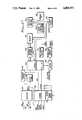
- FIG. 1is a block diagram of the house arrest monitoring system of the present invention
- FIG. 2is a perspective view of the tag that is worn by an individual being monitored by the system of FIG. 1;
- FIG. 3Aillustrates one manner in which the tag may be worn
- FIG. 3Bshows a perspective view of the FMD
- FIG. 4is a block diagram of the circuits contained in the tag of FIG. 1;
- FIG. 5is a schematic/logic diagram of the Tamper Detect and Strap Continuity Check circuits of the Tag of FIG. 4;
- FIG. 6is a cross-sectional view of the tag as it is worn or placed near the flesh or skin of its wearer, and illustrates the capacitive plates or electrodes contained within the tag and strap and their relationship to the flesh of the wearer;
- FIG. 7is a schematic/logic diagram of the Mode Control circuit of the Tag of FIG. 4;
- FIG. 8is a chart or table that illustrates the operating modes of the tag as controlled by the Mode Control circuit of FIG. 7;
- FIG. 9is a schematic/logic diagram of the ASMV and Encoding Logic of the Tag of FIG. 4;
- FIG. 10is a timing diagram that illustrates some of the key signals associated with the operation of the circuits of FIG. 9;
- FIG. 11is a schematic/logic diagram of the RF Modulator and Transmitter of the Tag of FIG. 4;
- FIG. 12is a block diagram of the FMD of FIG. 1.
- FIG. 1there is shown a block diagram of a house arrest monitoring system 30 in accordance with the present invention.
- the system 30includes a plurality of remote monitoring areas 32 and a central processing unit (CPU) 34.
- the CPU 34is coupled to the remote monitoring area 32, in accordance with the preferred embodiment, by way of a residential phone line 36.
- One or more conventional switching stations 38couple the phone line 36 to the CPU 34.
- Such switching stations 38are conventional switching stations commonly employed by the telephone company.
- each remote area 32there is included a field monitoring device (FMD) 40.
- the FMD 40receives periodic signals 42 from an identification tag 44.
- These identification signals 42contain information that uniquely identifies the tag 44 from which the signal originates, and that indicates the status of the circuits internal to the tag, and especially whether such circuits have sensed an attempt to remove the tag.
- the systemmay also include a repeater 46 that can be selectively positioned within the area 32.
- the purpose of the repeater 46is to receive the identification signals 42 from the tag 44 and retransmit these signals, after a short delay, to the FMD 40, to eliminate dead spots. Such retransmitted signals are identified in FIG. 1 as signals 42'.
- the CPU 34can be coupled through the telephone switching network 38 to a large number of remote monitoring areas. As will be explained below, the CPU 34 will typically randomly poll each of the remote monitoring areas with which it can establish a communication link. Coupled to the CPU 34 is at least one terminal 48 that provides a means for the CPU 34 to display the status of the various remote monitoring areas to which it is coupled, as well as to provide an operator the means for entering data or instructions into the CPU. Such terminals 48 are common in the art, typically including a CRT display screen and a keyboard. Also coupled to the CPU 34 is a printer 50 that can be used to print status reports and other information concerning the operation of the house arrest monitoring system 30. Some sample reports generated by the CPU 34 are contained in Appendix B.
- FIGS. 2, 3A and 3Bthere are shown perspective views of the tag 44 and the FMD 40 that are used within the remote monitoring area 32.
- the tag 44as best shown in FIG. 2, includes a case or housing 52 and a connecting strap 54.
- the tag 44is designed to be worn around a limb, such as an ankle 56, of its wearer, as shown in FIG. 3A.
- the housing 52is designed to be comfortably worn against the skin or flesh of its wearer.
- the tagis worn with just enough tension in the strap 54 to securely hold the housing 52 near the skin or flesh of the person being monitored.
- the case 52is made from a material that is impervious to the normal kinds of fluids with which the case may come in contact, such as water, thereby allowing the tag to be worn at all times.
- a material that is impervious to the normal kinds of fluids with which the case may come in contactsuch as water, thereby allowing the tag to be worn at all times.
- the only requirement to the useris that the tag be held near his or her flesh. Otherwise, a tamper condition will be detected by the circuits within the tag 44.
- the case 52is made from polystyrene, a type of plastic that is hard and durable. In the preferred embodiment, the tag measures no more than three inches square by one inch thick. It weighs less than eight ounces.
- the straps 54are made from a commercially available conductive material.
- FIG. 3Ba perspective view of the FMD 40 and receiver 124 is shown.
- the FMD 40is totally self contained. It is housed in a low profile package or housing 58 that is simple, unobstrusive, and that easily blends into the environment of a typical household.
- the FMD 40contains no visible dials or controls that are accessible to those in the household. However, it does include appropriate lights or other indicators to indicate the operating status thereof.
- Two antennas, 60 and 62,are connected to the receiver 124 which is attached to the FMD 40. These antennas comprise a length of wire that may be hung or draped down behind the unit in a location that is not visible to the casual observer. Also available at the rear of the device is a power line cord 64 and a phone line cord 66.
- the power line cord 64includes a twenty-four (24) volt transformer 68 for plugging into a standard 110 volt AC outlet socket.
- the phone line cord 66may contain a standard quick-connect modular phone jack 70 of the type used for connecting conventional telephones to a telephone line.
- special retainersmay be employed in conjunction with the conventional plugs 68 and 70, and their corresponding sockets, which retainers can only be removed with an appropriate tool or key, and which are wired into the tamper circuits of the FMD 40 (so that any attempt to remove the retainers in order to unplug either the transformer or phone jack signals a tamper condition).
- a low power circuit 80serves as an oscillator to provide a basic clock signal for operation of the circuit.
- Counter circuit 82count the ocurrence of clock cycles in order to regulate the time at which an identification signal 42 is transmitted from the tag. As indicated previously, an identification signal is transmitted about every 120 seconds.
- the oscillator 80 and the counter circuits 82define the 120 second interval (or other selected interval) between transmissions.
- the 120 second intervalis, of course, only exemplary. Other appropriate intervals may be used.
- the timing signals from the counter circuits 82are directed to encoding logic 84.
- a code select circuit 86defines a unique identification code that is also directed to the encoding logic 84.
- the encoding logic 84also receives an indication over signal line 88 as to whether a tamper condition has been detected.
- the tamper signal and code informationare combined in the encoding logic 84 at the appropriate time in order to create a word of encoded data that is passed on to an RF modulator and oscillator 90 over signal line 92.
- the RF modulator and oscillator 90generates an RF carrier signal, modulated with the encoded data, that is transmitted from antenna 96.
- the identification signal transmitted from the antenna signal 96is represented by the arrow 42 in the FIG. 4 and FIG. 1.
- a mode control circuit 98is also present within the tag 44.
- This mode control circuitdefines one of four possible operating modes of the circuits within the tag. These four operating modes are discussed in more detail below.
- the particular mode of operation for the tagis controlled by the selective closing or opening of reed switch 100.
- the reed switch 100is embedded within the tag 44, and the selective closure thereof can be effectuated by moving a magnet of sufficient strength within a prescribed distance of the tag. In this way, the operating mode of the tag can be selectively controlled without the use of any external switches, push buttons, or other manually actuated devices accessible on the surface of the tag case or housing 52.
- a tamper detect circuit 102determines whether the tag 44 is being held near the flesh or skin of the tag's wearer. If this circuit detects that the tag is not being held near the skin of the tag wearer, a TAMP signal is generated and sent to a set tamper alert circuit 106 over signal line 108. Similarly, if the strap continuity check circuit 104 determines that the continuity of the strap 54 has been broken, an appropriate alert signal is sent to the set tamper alert circuit 106.
- the set tamper alert circuit 106in response to either a TAMP signal from the tamper detect circuit 102, or an alert signal from the strap continuity check circuit 104, the set tamper alert circuit 106 generates a tamper signal that is sent to the encoding logic 84 over signal line 88.
- the function of the tamper detect circuit 102is to determine when the tag 44 is being held near the skin or flesh of its wearer and when it is not. This determination is made using a unique body mass detection circuit that includes a first capacitor plate 110 and a second capacitor plate or element 112.
- the second capacitive element or plate 112is realized with the conductive strap 54 (FIG. 2) that holds the tag 44 near the skin (body mass) of its wearer.
- the plate 110 and strap 112function as the plates of a capacitor, and the flesh 114 therebetween serves as the diaelectric material of the capacitor that separates one element from the other.
- An oscillator signal 116 from an oscillator(e.g., a signal derived from the oscillator 80) is applied to strap 112 and is capacitively coupled across the body mass to plate 110. So long as the body mass remains between strap 112 and plate 110, the signal coupled to plate 110 (a 1.1 KHz signal in the preferred embodiment) appears at the gate of field effect transistor (FET) switch F1.
- FETfield effect transistor
- This coupled signalincludes negative-going spikes that turn on F1 momentarily. These momentary turn ons are sufficient to maintain parallel capacitors C4 and C5 discharged to a positive volatage potential, +V.
- capacitors C4 and C5are connected in parallel across F1, with one side of this parallel combination being connected to +V and the other side --the drain side of F1--being connected to signal line 108.)
- signal line 108remains high, indicating a non tamper (NON TAMP) condition.
- switch F1does not turn on at all, and the drain side of capacitors C4 and C5 charges through resistor R3 to a negative potential (e.g., ground) causing the TAMP signal to go low.
- a low signal on signal line 108indicates the absence of flesh next to the tag 44.
- This low signalpasses through OR gate 124 and causes a flip flop 126 to be set.
- the Q output of flip flop 126functions as the tamper signal that is delivered to the encoding logic 84 (FIG. 4) over signal line 88.
- Both the gate 124 and the flip flop 126are part of the set tamper alert circuit 106. Also included as part of this circuit is an OR gate 128, the output of which is directed to the reset terminal of flip flop 126.
- One input of the OR gate 128is the magnet signal obtained from reed switch 100 (FIG. 4). This magnet signal is normally low in the absence of a magnet. The other input is connected to signal line 122 (Mode-2 signal line), and is low during normal operation. When either the Mode-2 signal or the magnet signal go high, the flip flop 126 is reset.
- the strap continuity check circuit 104As indicated previously the strap 54 is used to hold the tag 44 near the flesh of its wearer. This strap is made from conductive material. Accordingly, an electrical signal may pass therethrough. One end of the strap is connected to the oscillator signal 116 (a 1.1 KHz signal). The other end of strap 54 is connected to the cathode of diode CR1 of the continueity check circuit 104. The anode of diode CR1 is connected through resistor R8 to the other input of gate 124. This point is also coupled to a negative potential source (e.g., ground) through resistor R9. A holding capacitor C8 is connected to the junction of R8 and one of the inputs of gate 124.
- a negative potential sourcee.g., ground
- a magnetic reed switch 100is embedded in the tag 44 at a location where the application of an external magnet can close the switch.
- This magnetic reed switch 100is also identified in FIGS. 7 and 8 as SW1.
- the mode control circuit 98 of FIG. 4is realized with a D-type flip flop 98 as shown in FIG. 7.
- the D input of flip flop 98is connected to the Q* (inverse of Q) output of the same flip flop.
- This same signalalso serves as an ENABLE signal for oscillator 80 (FIG. 4). This signal must be low before oscillator 80 can begin to operate.
- the clock input, or C input, of the flip flop 98is connected to resistor R10, capacitor C9, and reed switch 100.
- resistor R10As indicated in FIG. 7, one side of reed switch 100, which is normally open in the absence of a magnetic field, is tied to the positive voltage reference +V. The other side is tied to one end of resistor R10. Capacitor C9 parallels resistor R10.
- the clock input of flip flop 98is connected to that side of R10 that is connected to the magnetic reed switch 100. Accordingly, when the reed switch 100 is open, the signal appearing on the clock input is low.
- flip flop 98When the reed switch 100 is closed, as when a magnetic field is applied, the clock input rises to the +V potential, thereby changing the state of flip flop 98. (As depicted in the figure, flip flop 98 is clocked on the leading or positive-going edge of the clock signal.)
- FIG. 8defines the various operating modes associated with the mode control circuit 98.
- flip-flop 98When initially manufactured, flip-flop 98 is reset, meaning that the Mode-1 signal is "0", and the Mode-2 signal is "1". This state remains until the reed switch 100 is closed. In this initial mode of operation, all of the circuits of the tag, with the exception of flip flop 98, are off, thereby preserving the battery life of the battery 101 included in the tag. It is noted that even though power is applied to flip flop 98, when this flip-flop is a CMOS device, it is also effectively off inasmuch as it draws very little current, except when it is switching from one state to the other.
- the flip flop 98When a magnet is first applied so as to close the magnetic reed switch 100 (SW1), the flip flop 98 is latched such that the Mode-1 signal is high, or a logic "1", and the Mode-2 signal is low, or a logic "0". These two signals, in this state, coupled with the Switch (Magnet) signal on signal line 99, define a testing/start-up mode of operation for the tag 44. In this mode of operation, the identification signal is transmitted continuously by the tag. When the external magnet 97 is removed, thereby opening the magnetic reed switch 100, the tag reverts to its normal mode of operation wherein the identification signal is transmitted about every 120 seconds. During this normal mode of operation, the Switch signal is low, the Mode-1 signal remains high, and the Mode-2 signal remains low.
- a CW transmit mode of operationis initiated wherein the tag transmits a continuous RF signal which contains no data.
- This mode of operationis useful during initial set-up and testing.
- the normal mode of operationis reentered simply by removing, reapplying, and removing the magnet, thereby cycling the flip-flop 98 back through the off and testing/start-up modes to the normal run mode.
- the oscillator 80is a very low power circuit.
- the circuit operationis more or less conventional. That is, two NPN transistors T1 and T2 are cross coupled such than when one transistor is off, the other is on, and vice-versa.
- the cross couplingoccurs through the use of capacitor C10, coupling the base of T1 to the collector of T2; and through the use of capacitor C11, coupling the base of T2 to the collector of T1.
- the emitters of T1 and T2are tied together and connected to the Oscillator Enable line coming from the Mode Control Circuit 98 (FIGS. 4 and 7).
- the oscillator 80can not begin operating until the Enable line goes low. Because it is desirable to operate the oscillator 80 at very low power levels, the currents that flow through T1 and T2 are made very small by making the values of resistors R11 and R15 very large.
- the frequency of operationis controlled by the values of R12 and C12, and R13 and C10. In the preferred embodiment, the frequency of operation is set at about 2.2 KHz.
- Coupling capacitor C12transfers the periodic signal appearing at the collector of T2 to the base of PNP transistor T3, the emitter of which is tied to the +V potential.
- Resistor R16is a bias resistor that is connected between the base and emitter of T3.
- the operation of stage T3serves to square up the edges of the periodic basic clock signal that is generated by the ASMV operation of T1 and T2.
- the collector of T3, on which appears the basic clock signal,is directly connected to the counter circuit 82.
- Counter Circuits 82are realized with CMOS integrated circuits (IC's) U1 and U2. Each of these IC's contain a sequence of flip flops, the respective outputs of which are designated in the figure as Q1, Q2, Q3, . . . Q12.
- the IC's U1 and U2are of a type that are readily available from numerous IC vendors under the generic title "12-bit binary counter" and the generic number 4040. (For example, if these devices are procured from Motorola, they are identified as part number MC14040B.)
- the respective output signals Q1, Q2, etc., from U1 and U2comprise square waves that have frequencies that are successively divided by two.
- the first state output (designated as Q1 in FIG. 9, although sometimes the first stage is referred to as Q0 in the art) signalhas a frequency that is 1/2 that of the input signal (received from the oscillator 80).
- the Q2 signalhas a frequency that is 1/2 that of Q1.
- the Q3 signalhas a frequency that is 1/2 that of Q2, or 1/4 that of Q1, and so on. All of these signals are combined in the encoding logic 84 in such a way that an encoded data signal 110 is ultimately generated, as best illustrated in the timing diagram of FIG. 10.
- Code Select circuitrysimply comprises a connection block where up to 7 bits can be selectively hard-wired to be either a logic "1” or a logic "0" by the application of jumper wires, or equivalent, between a ground bus 112 or a voltage bus 114 and an output pin.
- the code word set by the jumper wires shown in FIG. 9is thus "0010110", assuming ground is a logic "0” and +V is a logic "1".
- the bits defined by the code wordare serially passed out the output terminal of U3 (designated as pin "Z") to pin 6 of NOR gate U4. These bits are then interleaved into the processing of the other timing signals by gates U4, U5 and U6 to produce the data signal 110 appearing on signal line 110 (pin 11 of U4), as illustrated in the timing diagram of FIG. 10. It is noted that the signals shown in FIG. 10 are exemplary only, and are not intended to be limiting.
- NPN transistor T4, crystal Y1, inductor L1, and capacitor C13comprise a local oscillator stage that is enabled whenever the Transmit line 94 is high. In the preferred embodiment this stage oscillates at approximately 75 MHz.
- the Transmit signalis coupled to the base of T4 through resistor R20, thereby providing a bias signal that allows T4 to oscillate at a frequency that is controlled by the crystal Y1.
- the Switch signal 99is also coupled to the base of T1 through resistor R21. During normal operation, it will be recalled that the Switch signal is low, and therefore it does not influence the local oscillator stage. However, during certain modes of operation (see FIGS. 7 and 8), this signal goes high (when reed switch 100 closes), thereby enabling the local oscillator to generate the 75 MHz. signal.
- Capacitor C17 and resistor R22are connected in series in the collector circuit of T4.
- a primary winding of transformer TR-1is connected in parallel with C17.
- the inductance associated with TR-1 and the capacitance of C17are selected to be tuned at approximately 152 MHz., thereby causing these components to function as a frequency doubler circuit.
- a secondary winding of TR-1is coupled to the bases of NPN transistor pair T6 and T7 through capacitors C15 and C16 respectively.
- the emitters of T6 and T7are connected together, as are the collectors.
- Resistors R24 and R25are connected to the base terminals of T6 and T7 respectively to provide a bias current therefor.
- the joined emittersare connected to the collector of NPN transistor T5, the base of which is coupled through resistor R26 to the data signal line 110.
- Transistors T6 and T7function as a rectifier circuit with respect to the 150 MHz signal applied to their base terminals, thereby serving the function of another frequency doubler circuit.
- the emitter of another NPN transistor T8, with its base terminal grounded,is connected to the collectors of T6 and T7.
- the collector of T8is connected to one side of a tank circuit made up of capacitor C18 and inductor L2.
- Inductor L2functions as the antenna 96 of the tag 44.
- the other side of this tank circuitis coupled to the +V potential through resistor R23.
- Capaitors C19 and C20are also used to shunt undesired high frequencies to ground appearing at the junction of C18, L2 and R23.
- Transistors T6, T7 and T8may be realized with an MPS 5179 transistor, manufactured by Motorola.
- Transistor T5may be a 2N3904.
- the tag 44generates an identification signal 42 that is periodically transmitted, approximately every 120 seconds, in a group of short data bursts.
- This identification signalis generated at all times regardless of where the tag is located, that is, regardless of where the person being monitored is located. (Only when a magnet is used to enable a different operating mode of the tag is this pattern of generating the identification signal not followed.) If the person being monitored is within the designated area 32 (FIG. 1), then the identification signal 42 will be received by the FMD 40.
- FIG. 12shows a block diagram of a preferred embodiment of the FMD 40. It includes two antennas 60 and 62 that are spaced-apart a distance that is approximately 1/4 wavelength of the RF carrier signal. This distance empirically determined to be optimum for this applicate, although other distance may be used. As described in connection with FIG. 11, in the preferred embodiment, the RF carrier signal is approximately 303 MHz. The wavelength of a 303 MHz. signal is approximately one meter, or about 39 inches. Hence, in accordance with the teachings of the present invention, the antennas 60 and 62 are spaced apart about 9.8 inches.
- the receiver 124receives the signal 42, demodulates it, and passes the demodulated data through switch SW2 to a microprocessor 130.
- Switch SW2(also identified as block 126 in FIG. 12) is controlled by watchdog circuit 128.
- the purpose of the watchdog circuit 128is to monitor the operation of the FMD, by monitoring the power control circuit 144 (described below), to ensure that the FMD operation is normal. If anything unusual occurs in the power circuits, SW2 is opened in order to prevent data from being passed to the microprocessor 130 that might be misinterpreted.
- Microprocessor 130controls the operation of the FMD in accordance with programs stored in memory 134. These programs control the operation of the FMD so that its desired function is achieved.
- Address decode and latch circuitry 132is used by the microprocessor 130 to aid in the accessing of information in memory 134.
- Data bus 133allows data to be passed between the memory 134 and the microprocessor 130, as well as to the display and set-up Control circuits 140 and the calendar clock circuits 142.
- the display and set-up control circuits 140interface with manual set devices 136 and audio and visual display and alarm devices 138.
- Microprocessor 130also is connected to modem 148.
- Modem 148allows data to be received or sent over the telephone lines.
- Automatic call-up or dialing circuitsare included to enable the FMD to receive or send calls.
- the FMDalso includes a power supply 146 that provides power to all of the circuits therein.
- this power supplyincludes battery backup in the event that line power is lost or interrupted.
- the power control circuit 144advantageously operates the FMD in either a sleep state or a wake-up state. In the sleep state, most of the circuits, with the exception of the calendar clock circuits and certain other circuits that must be fully awake at all times, are essentially turned off (power is not applied thereto), thereby saving power that would otherwise be dissipated.
- Memory 134is nonvolatile memory, meaning that the program instructions remain stored therein whether power is applied or not.
- the periodic check signalis generated, in the preferred embodiment of the invention, approximately once each minute.
Landscapes
- Engineering & Computer Science (AREA)
- Physics & Mathematics (AREA)
- General Physics & Mathematics (AREA)
- Theoretical Computer Science (AREA)
- Computer Hardware Design (AREA)
- Microelectronics & Electronic Packaging (AREA)
- Computer Networks & Wireless Communication (AREA)
- Artificial Intelligence (AREA)
- Computer Vision & Pattern Recognition (AREA)
- Computer Security & Cryptography (AREA)
- Alarm Systems (AREA)
Abstract
Description
Claims (16)
Priority Applications (1)
| Application Number | Priority Date | Filing Date | Title |
|---|---|---|---|
| US07/231,823US4885571A (en) | 1986-04-15 | 1988-08-12 | Tag for use with personnel monitoring system |
Applications Claiming Priority (2)
| Application Number | Priority Date | Filing Date | Title |
|---|---|---|---|
| US85283186A | 1986-04-15 | 1986-04-15 | |
| US07/231,823US4885571A (en) | 1986-04-15 | 1988-08-12 | Tag for use with personnel monitoring system |
Related Parent Applications (1)
| Application Number | Title | Priority Date | Filing Date |
|---|---|---|---|
| US85283186AContinuation | 1986-04-15 | 1986-04-15 |
Related Child Applications (1)
| Application Number | Title | Priority Date | Filing Date |
|---|---|---|---|
| US07/446,212ContinuationUS4952913A (en) | 1986-04-15 | 1989-12-04 | Tag for use with personnel monitoring system |
Publications (1)
| Publication Number | Publication Date |
|---|---|
| US4885571Atrue US4885571A (en) | 1989-12-05 |
Family
ID=26925466
Family Applications (1)
| Application Number | Title | Priority Date | Filing Date |
|---|---|---|---|
| US07/231,823Expired - LifetimeUS4885571A (en) | 1986-04-15 | 1988-08-12 | Tag for use with personnel monitoring system |
Country Status (1)
| Country | Link |
|---|---|
| US (1) | US4885571A (en) |
Cited By (157)
| Publication number | Priority date | Publication date | Assignee | Title |
|---|---|---|---|---|
| US4952913A (en)* | 1986-04-15 | 1990-08-28 | B. I. Incorporated | Tag for use with personnel monitoring system |
| GB2230164A (en)* | 1989-03-01 | 1990-10-10 | Marconi Electronic Devices | Electronic human tagging arrangement detects if tag is removed |
| US5032823A (en)* | 1988-05-27 | 1991-07-16 | Digital Products Corporation | Secure personnel monitoring system |
| US5038137A (en)* | 1990-03-26 | 1991-08-06 | Stephen Lloyd | Sleep posture monitor and alarm system |
| US5075670A (en)* | 1990-08-01 | 1991-12-24 | Digital Products Corporation | Personnel monitoring tag with tamper detection and secure reset |
| WO1992005527A1 (en)* | 1990-09-20 | 1992-04-02 | Moody Thomas O | A personnel location monitoring system and method |
| US5119072A (en)* | 1990-12-24 | 1992-06-02 | Hemingway Mark D | Apparatus for monitoring child activity |
| USD329431S (en) | 1989-04-25 | 1992-09-15 | Neil Wood | Transmitter |
| GB2262015A (en)* | 1991-11-27 | 1993-06-02 | Us Energy | Non-contact tamper sensing by electronic means |
| US5218344A (en)* | 1991-07-31 | 1993-06-08 | Ricketts James G | Method and system for monitoring personnel |
| USD338846S (en) | 1990-09-06 | 1993-08-31 | Jewell Charles D | Child locator receiver |
| US5241923A (en)* | 1992-07-23 | 1993-09-07 | Pole/Zero Corporation | Transponder control of animal whereabouts |
| US5255306A (en)* | 1991-01-10 | 1993-10-19 | Bi Inc. | Cellular interface unit for use with an electronic house arrest monitoring system |
| US5266944A (en)* | 1991-06-26 | 1993-11-30 | Bodyguard Technologies, Inc. | Electronic system and method for monitoring abusers for compliance with a protective order |
| US5276431A (en)* | 1992-04-29 | 1994-01-04 | Checkpoint Systems, Inc. | Security tag for use with article having inherent capacitance |
| US5298884A (en)* | 1992-10-16 | 1994-03-29 | Bi Incorporated | Tamper detection circuit and method for use with wearable transmitter tag |
| US5396215A (en)* | 1992-10-28 | 1995-03-07 | Hinkle; Terry A. | Vehicle operation inhibitor control apparatus |
| USD356516S (en) | 1992-04-24 | 1995-03-21 | Price James R | Signalling transmitter for monitoring the location of people |
| EP0654772A1 (en)* | 1993-11-18 | 1995-05-24 | Motorola, Inc. | Body detector |
| EP0575753A3 (en)* | 1992-06-16 | 1995-08-16 | Motorola Inc | Electronic monitoring system |
| US5455851A (en)* | 1993-07-02 | 1995-10-03 | Executone Information Systems, Inc. | System for identifying object locations |
| US5504474A (en)* | 1994-07-18 | 1996-04-02 | Elmo Tech Ltd. | Tag for electronic personnel monitoring |
| US5521601A (en)* | 1995-04-21 | 1996-05-28 | International Business Machines Corporation | Power-efficient technique for multiple tag discrimination |
| US5523740A (en)* | 1995-04-24 | 1996-06-04 | Detection Systems, Inc. | Wearable transmitter assembly |
| US5525969A (en)* | 1992-05-18 | 1996-06-11 | Ladue; Christoph K. | Monitoring device for location verification |
| US5543780A (en)* | 1995-06-16 | 1996-08-06 | Secure Care Products, Inc. | Monitoring tag with removal detection |
| DE19509092A1 (en)* | 1995-03-15 | 1996-09-19 | Norbert Schaaf | Monitoring for presence of spare-time leisure craft, e.g. boat or yacht in marina |
| US5594786A (en)* | 1990-07-27 | 1997-01-14 | Executone Information Systems, Inc. | Patient care and communication system |
| FR2742903A1 (en)* | 1995-12-20 | 1997-06-27 | Daimler Benz Ag | DEVICE FOR BODY-RELATED DATA TRANSMISSION BETWEEN TWO TERMINALS |
| WO1997024042A1 (en)* | 1995-12-29 | 1997-07-10 | Sergei Feodosievich Konovalov | Sliding clasp fastener |
| US5650766A (en)* | 1995-04-24 | 1997-07-22 | Detection Systems, Inc. | Wearable transmitter with optical tamper detection |
| US5661458A (en)* | 1993-08-18 | 1997-08-26 | Bi Incorporated | Electronic house arrest monitoring system with automatic fee collection feature |
| US5742233A (en)* | 1997-01-21 | 1998-04-21 | Hoffman Resources, Llc | Personal security and tracking system |
| US5745037A (en)* | 1996-06-13 | 1998-04-28 | Northrop Grumman Corporation | Personnel monitoring tag |
| US5790946A (en)* | 1993-07-15 | 1998-08-04 | Rotzoll; Robert R. | Wake up device for a communications system |
| US5831535A (en)* | 1997-07-24 | 1998-11-03 | Elmo-Tech Ltd. | Electronic monitoring device and monitoring system including same |
| US5883576A (en)* | 1998-01-14 | 1999-03-16 | De La Huerga; Carlos | Identification bracelet with electronics information |
| US5912623A (en)* | 1997-11-28 | 1999-06-15 | Alert Systems Corporation | House arrest monitoring system with improved tamper detection |
| US5911199A (en)* | 1998-01-26 | 1999-06-15 | Eltrex 4, Inc. | Pressure sensitive animal training device |
| US5962834A (en)* | 1997-03-17 | 1999-10-05 | Markman; Herbert L. | Inventory tracking and management apparatus with multi-function encoding unit |
| US6029102A (en)* | 1997-07-01 | 2000-02-22 | Elsman; James L. | Driver control display system for a vehicle |
| US6028519A (en)* | 1997-09-05 | 2000-02-22 | R. F. Tracking L.L.C. | Tamper-proof security device and system |
| US6040774A (en)* | 1998-05-27 | 2000-03-21 | Sarnoff Corporation | Locating system and method employing radio frequency tags |
| US6058374A (en)* | 1996-06-20 | 2000-05-02 | Northrop Grumman Corporation | Inventorying method and system for monitoring items using tags |
| US6064308A (en)* | 1996-10-25 | 2000-05-16 | Pole/Zero Corporation | RF signaling system and system for controlling the whereabouts of animals using same |
| US6072396A (en)* | 1994-12-30 | 2000-06-06 | Advanced Business Sciences | Apparatus and method for continuous electronic monitoring and tracking of individuals |
| US6084513A (en)* | 1997-09-26 | 2000-07-04 | Innovative Control Systems | Method and apparatus for tracking a patient |
| US6104009A (en)* | 1998-12-07 | 2000-08-15 | Hp Intellectual Corp. | Electrical appliance having user proximity sensor |
| FR2791452A1 (en)* | 1999-03-22 | 2000-09-29 | Catherine Claude Mari Coutelou | Monitoring apparatus for group of people, e.g. for use by person in charge of school trip, receives limited-range radio signals from tags carried by group members, indicating missing individual in case of non-reception |
| US6144303A (en)* | 1999-02-01 | 2000-11-07 | Exi Wireless Systems, Inc. | Tag and system for patient safety monitoring |
| US6166643A (en)* | 1997-10-23 | 2000-12-26 | Janning; Joseph J. | Method and apparatus for controlling the whereabouts of an animal |
| WO2001044836A1 (en)* | 1999-12-17 | 2001-06-21 | Italdata Ingegneria Dell'idea S.P.A. | Surveillance and remote alarm system for persons subject to limitation of freedom of movement |
| FR2808380A1 (en)* | 2000-04-28 | 2001-11-02 | Jay Electronique Sa | Small distance object state control/protection having remote located transmitter/receiver /control mechanism radiating object placed transponder with object state setting/removing radiated signal oscillator return |
| US6346886B1 (en)* | 1996-12-20 | 2002-02-12 | Carlos De La Huerga | Electronic identification apparatus |
| US20020044043A1 (en)* | 1990-07-27 | 2002-04-18 | John Chaco | Patient care and communication system |
| US6446049B1 (en) | 1996-10-25 | 2002-09-03 | Pole/Zero Corporation | Method and apparatus for transmitting a digital information signal and vending system incorporating same |
| US6510380B1 (en) | 1999-03-31 | 2003-01-21 | C2 Global Technologies, Inc. | Security and tracking system |
| US20030121985A1 (en)* | 2000-02-04 | 2003-07-03 | Michael Baldischweiler | Transponder, especially for a contactless chip card |
| US6606556B2 (en) | 1999-03-31 | 2003-08-12 | C2 Global Technologies, Inc. | Security and tracking system |
| US6674368B2 (en) | 2000-08-28 | 2004-01-06 | Continental Divide Robotics, Inc. | Automated tracking system |
| US20040014478A1 (en)* | 1997-01-21 | 2004-01-22 | Hoffman Resources Llc | Personal security and tracking system |
| US20040021570A1 (en)* | 1998-09-11 | 2004-02-05 | Key-Trak, Inc. | Mobile object tracking system |
| US6693543B1 (en) | 1999-05-05 | 2004-02-17 | Guidance Control Systems Limited | Tagging device |
| US6703936B2 (en) | 2001-09-28 | 2004-03-09 | Veridian Engineering, Inc. | System and method for tracking movement of individuals |
| US20040095241A1 (en)* | 1998-09-11 | 2004-05-20 | Key-Trak, Inc. | Object tracking system with non-contact object detection and identification |
| US20040111323A1 (en)* | 2002-12-05 | 2004-06-10 | Niederland Roger A | Object controlled access and inventory system |
| US20040113786A1 (en)* | 2001-06-26 | 2004-06-17 | Key-Trak, Inc. | Object tracking method and system with object identification and verification |
| US20040145520A1 (en)* | 2001-05-02 | 2004-07-29 | Richardson David L. | Energy conserving satellite tracking tag |
| US6774797B2 (en) | 2002-05-10 | 2004-08-10 | On Guard Plus Limited | Wireless tag and monitoring center system for tracking the activities of individuals |
| US20040174264A1 (en)* | 2003-03-05 | 2004-09-09 | Dmatek Ltd. | Monitoring and tracking network |
| US20040189471A1 (en)* | 2003-01-31 | 2004-09-30 | Ciarcia Daniel J. | System and methods for providing secure environments |
| US20040189470A1 (en)* | 2003-03-26 | 2004-09-30 | Girvin Joshua M. | Non-reusable identification device |
| US6804578B1 (en)* | 2001-10-12 | 2004-10-12 | Touraj Ghaffari | Real time total asset visibility system |
| US20040229560A1 (en)* | 2002-10-10 | 2004-11-18 | Maloney William C. | Methods of tracking and verifying human assets |
| US20040226757A1 (en)* | 2003-05-16 | 2004-11-18 | Kasinoff Harvey A. | Random weight food product pricing scale with automated login capability |
| US20050024211A1 (en)* | 2001-04-26 | 2005-02-03 | Maloney William C. | Key control system using separated ID and location detection mechanisms |
| US20050040232A1 (en)* | 1998-09-11 | 2005-02-24 | Key-Trak, Inc. | Object control and tracking system with zonal transition detection |
| US6889135B2 (en) | 1999-03-31 | 2005-05-03 | C2 Global Technologies, Inc. | Security and tracking system |
| US6891473B2 (en) | 1998-09-11 | 2005-05-10 | Key-Trak, Inc. | Object carriers and lighted tags for an object control and tracking system |
| US20050110636A1 (en)* | 2001-10-12 | 2005-05-26 | Touraj Ghaffari | Real time total asset visibility system |
| US20050136912A1 (en)* | 1999-03-31 | 2005-06-23 | Curatolo Benedict S. | Security and tracking system |
| US20050163511A1 (en)* | 2004-01-27 | 2005-07-28 | Cicchiello James M. | Dynamic optical tag |
| US20050163293A1 (en)* | 2003-05-19 | 2005-07-28 | Hawthorne Jeffrey S. | Bio-information sensor monitoring system and method |
| US20050170789A1 (en)* | 2004-02-04 | 2005-08-04 | Consolazio Stephen J. | E-Band radio transceiver architecture and chip set |
| USRE38838E1 (en) | 1997-09-10 | 2005-10-18 | Taylor Jr John E | Monitoring system |
| US6958698B2 (en)* | 1998-09-11 | 2005-10-25 | Key-Trak, Inc. | Tamper detection and prevention for an object control and tracking system |
| US7006894B2 (en) | 1996-12-20 | 2006-02-28 | Carlos De La Huerga | Interactive medication cassette |
| US7005984B2 (en) | 1998-09-11 | 2006-02-28 | Key-Trak, Inc. | Object carriers for an object control and tracking system |
| US20060055537A1 (en)* | 2004-09-15 | 2006-03-16 | Radarfind Corporation | Methods, identification tags and computer program products for automated location and monitoring of mobile devices |
| US20060055536A1 (en)* | 2004-09-15 | 2006-03-16 | Radarfind Corporation | Methods, systems and computer program products for automated location and monitoring of mobile devices |
| US20060076402A1 (en)* | 2004-10-08 | 2006-04-13 | Proximities, Inc. | Method for authorizing an auxiliary account using identification wristbands |
| US20060092028A1 (en)* | 2004-10-08 | 2006-05-04 | Proximities, Inc. | Identification band using shorting wire for enabling/disabling an RFID transponder contained thereon |
| US7042337B2 (en) | 1997-11-07 | 2006-05-09 | Hill-Rom Services, Inc. | Communication and data entry device |
| US7061831B2 (en) | 1997-03-28 | 2006-06-13 | Carlos De La Huerga | Product labeling method and apparatus |
| US7071827B2 (en) | 2000-06-16 | 2006-07-04 | Secure Care Products, Inc. | Apparatus and system for identifying infant-mother match |
| US7102509B1 (en)* | 2003-01-11 | 2006-09-05 | Global Tel★Link Corporation | Computer interface system for tracking of radio frequency identification tags |
| US20060202837A1 (en)* | 2003-05-19 | 2006-09-14 | Alcohol Monitoring Systems, Llc | Method and apparatus for remote blood alcohol monitoring |
| US7116228B1 (en) | 2001-02-20 | 2006-10-03 | Key Control Holding, Inc. | Asset management system |
| US7132944B1 (en)* | 2003-06-06 | 2006-11-07 | Innovative Control Systems, Inc. | Microprocessor controlled security tag |
| US20060290519A1 (en)* | 2005-06-22 | 2006-12-28 | Boate Alan R | Two-way wireless monitoring system and method |
| CN1312630C (en)* | 2003-10-09 | 2007-04-25 | 株式会社日立制作所 | Individual certification system, certification label and individual certification method |
| US7216802B1 (en) | 1997-10-21 | 2007-05-15 | Carlos De La Huerga | Method and apparatus for verifying information |
| US20070120381A1 (en)* | 2005-11-15 | 2007-05-31 | Jakob Ehrensvard | Electronic tamper evident seal |
| US20070120687A1 (en)* | 2005-11-29 | 2007-05-31 | Lerch John W | Identification band using a conductive fastening for enhanced security and functionality |
| US7242306B2 (en) | 2001-05-08 | 2007-07-10 | Hill-Rom Services, Inc. | Article locating and tracking apparatus and method |
| US7248933B2 (en) | 2001-05-08 | 2007-07-24 | Hill-Rom Services, Inc. | Article locating and tracking system |
| US20080030346A1 (en)* | 2003-01-29 | 2008-02-07 | Despotis George J | Integrated patient diagnostic and identification system |
| US7336174B1 (en) | 2001-08-09 | 2008-02-26 | Key Control Holding, Inc. | Object tracking system with automated system control and user identification |
| US7342494B2 (en) | 1995-09-08 | 2008-03-11 | Key Control Holding, Inc. | Inventoriable-object control and tracking system |
| US20080088437A1 (en)* | 2005-05-06 | 2008-04-17 | Omnilink Systems, Inc. | System and method for monitoring alarms and responding to the movement of individuals and assets |
| US20080223281A1 (en)* | 2007-03-16 | 2008-09-18 | Minarovic Joe T | Pop-up cable electronic marker |
| USD578918S1 (en) | 2007-05-01 | 2008-10-21 | Omnilink Systems, Inc. | Offender monitor |
| US7562445B2 (en) | 2005-07-18 | 2009-07-21 | Bartronics America, Inc. | Method of manufacture of an identification wristband construction |
| US7576650B1 (en) | 2001-10-12 | 2009-08-18 | Touraj Ghaffari | Real time total asset visibility system |
| US7598854B2 (en) | 2005-03-01 | 2009-10-06 | Chon Meng Wong | System and method for creating a proximity map of plurality of living beings and objects |
| US7619513B2 (en) | 2003-10-03 | 2009-11-17 | Satellite Tracking Of People Llc | System and method for tracking movement of individuals |
| US20100007498A1 (en)* | 2008-07-10 | 2010-01-14 | Jackson Stephen S | Rotatable Tags for Automated Location and Monitoring of Moveable Objects and Related Systems |
| US20100084200A1 (en)* | 2008-10-06 | 2010-04-08 | Juan-Castellanos Santos J | Food product pricing scale with automated multi-language interface |
| US20100090826A1 (en)* | 2008-10-10 | 2010-04-15 | Brian Sean Moran | Technique for Detecting Tracking Device Tampering Using An Auxiliary Device |
| US7715277B2 (en) | 1996-12-20 | 2010-05-11 | Carlos De La Huerga | Interactive medication container |
| US20100123589A1 (en)* | 2008-11-14 | 2010-05-20 | Bi Incorporated | Systems and Methods for Adaptive Monitoring of Physical Movement |
| US7734476B2 (en) | 2002-09-27 | 2010-06-08 | Hill-Rom Services, Inc. | Universal communications, monitoring, tracking, and control system for a healthcare facility |
| US7737841B2 (en) | 2006-07-14 | 2010-06-15 | Remotemdx | Alarm and alarm management system for remote tracking devices |
| US7804412B2 (en) | 2005-08-10 | 2010-09-28 | Securealert, Inc. | Remote tracking and communication device |
| US7933780B2 (en) | 1999-10-22 | 2011-04-26 | Telaric, Llc | Method and apparatus for controlling an infusion pump or the like |
| US7936262B2 (en) | 2006-07-14 | 2011-05-03 | Securealert, Inc. | Remote tracking system with a dedicated monitoring center |
| US20110133928A1 (en)* | 2009-12-03 | 2011-06-09 | Bi Incorporated | Systems and Methods for Variable Collision Avoidance |
| US20110133937A1 (en)* | 2009-12-03 | 2011-06-09 | Bi Incorporated | Systems and Methods for Disrupting Criminal Activity |
| US20110154887A1 (en)* | 2007-03-06 | 2011-06-30 | Bi Incorporated | Transdermal Portable Alcohol Monitor and Methods for Using Such |
| US7978564B2 (en) | 1997-03-28 | 2011-07-12 | Carlos De La Huerga | Interactive medication container |
| US8103047B1 (en) | 2006-07-19 | 2012-01-24 | Stanley Security Solutions, Inc. | Signaling device |
| US8115621B2 (en)* | 2007-05-01 | 2012-02-14 | Yoganand Rajala | Device for tracking the movement of individuals or objects |
| DE102010062189A1 (en)* | 2010-11-30 | 2012-05-31 | Matthias Klepper | System for detecting location of animal e.g. dog, has radio frequency signal receiver with radio frequency signal antenna, which is mounted on flexible ground plane of circuit board |
| US8232876B2 (en) | 2008-03-07 | 2012-07-31 | Securealert, Inc. | System and method for monitoring individuals using a beacon and intelligent remote tracking device |
| US20120229261A1 (en)* | 2011-03-09 | 2012-09-13 | Samsung Electronics Co. Ltd. | Apparatus for low power wireless communication |
| US20120246801A1 (en)* | 2011-03-03 | 2012-10-04 | Cutler David M | Water Sensing Electrode Circuit |
| US20130012795A1 (en)* | 2011-07-05 | 2013-01-10 | Collar Id Llc | Apparatus and methods for sensing a parameter with a restraint device |
| US8410926B1 (en) | 2010-05-07 | 2013-04-02 | Rf Technologies, Inc. | Alarm for security tag |
| US8466795B2 (en) | 1997-01-21 | 2013-06-18 | Pragmatus Mobile LLC | Personal security and tracking system |
| US8489113B2 (en) | 2010-02-09 | 2013-07-16 | Omnilink Systems, Inc. | Method and system for tracking, monitoring and/or charging tracking devices including wireless energy transfer features |
| US8514070B2 (en) | 2010-04-07 | 2013-08-20 | Securealert, Inc. | Tracking device incorporating enhanced security mounting strap |
| US8657744B2 (en) | 2009-03-23 | 2014-02-25 | Bi Incorporated | Systems and methods for transdermal secretion detection |
| US8717174B2 (en) | 2010-09-07 | 2014-05-06 | 3M Innovative Properties Company | Monitoring apparatus for a tag having an engaged and a non-engaged mode |
| US8797210B2 (en) | 2006-07-14 | 2014-08-05 | Securealert, Inc. | Remote tracking device and a system and method for two-way voice communication between the device and a monitoring center |
| US8831627B2 (en) | 2005-04-06 | 2014-09-09 | Omnilink Systems, Inc. | System and method for tracking, monitoring, collecting, reporting and communicating with the movement of individuals |
| US20140292516A1 (en)* | 2005-07-27 | 2014-10-02 | Autronic Plastics, Inc. | Anti-theft security device and perimeter detection system |
| US9215578B2 (en) | 2012-01-27 | 2015-12-15 | Omnilink Systems, Inc. | Monitoring systems and methods |
| US9355548B2 (en) | 2009-12-03 | 2016-05-31 | Bi Incorporated | Systems and methods for contact avoidance |
| US20160371517A1 (en)* | 2015-06-16 | 2016-12-22 | Motorola Mobility Llc | Person-Centric Activation of Radio Frequency Identification (RFID) Tag |
| ITUB20153548A1 (en)* | 2015-09-11 | 2017-03-11 | Massimo Nais | ANTI-THEFT DEVICE PARTICULARLY, BUT NOT EXCLUSIVELY, FOR TWO-WHEEL VEHICLES |
| EP3255619A1 (en) | 2016-06-10 | 2017-12-13 | Micro APPS Group Inventions LLC | Wireless personal safety device |
| EP3621047A1 (en)* | 2018-09-06 | 2020-03-11 | Nxp B.V. | System and method for detecting tampering with a product |
| US20210125715A1 (en)* | 2005-10-25 | 2021-04-29 | Nxstage Medical, Inc. | Safety Features for Medical Devices Requiring Assistance and Supervision |
| US11308462B2 (en) | 2014-05-13 | 2022-04-19 | Clear Token Inc | Secure electronic payment |
| US11665507B2 (en) | 2020-09-15 | 2023-05-30 | Bi Incorporated | Systems and methods for intercept directing in a monitoring system |
| US11701007B2 (en) | 2020-08-28 | 2023-07-18 | Bi Incorporated | Systems and methods for biometric tamper detection |
| US11900778B1 (en) | 2023-03-29 | 2024-02-13 | Micro Apps Group Inventions, LLC | System for improving safety in schools |
Citations (10)
| Publication number | Priority date | Publication date | Assignee | Title |
|---|---|---|---|---|
| US3478344A (en)* | 1965-06-21 | 1969-11-11 | Ralph K Schwitzgebel | Behavioral supervision system with wrist carried transceiver |
| US3882277A (en)* | 1972-04-20 | 1975-05-06 | American Optical Corp | Electrocardiographic telemetry and telephone transmission link system |
| US3898984A (en)* | 1974-02-04 | 1975-08-12 | Us Navy | Ambulatory patient monitoring system |
| US4259665A (en)* | 1979-05-29 | 1981-03-31 | Rmr Systems, Inc. | Driver sleep or fatigue alarm |
| GB2141006A (en)* | 1983-04-21 | 1984-12-05 | Intellitech Corp | A system for location indentification motion measurement and/or systematic counting analysis and control |
| US4598275A (en)* | 1983-05-09 | 1986-07-01 | Marc Industries Incorporated | Movement monitor |
| US4622544A (en)* | 1985-05-13 | 1986-11-11 | Lifeline Systems, Inc. | Low battery indicator |
| US4665387A (en)* | 1983-07-13 | 1987-05-12 | Knogo Corporation | Method and apparatus for target deactivation and reactivation in article surveillance systems |
| US4682155A (en)* | 1986-01-13 | 1987-07-21 | Central Security Mfg. Corp. | Personnel security system |
| US4747120A (en)* | 1985-08-13 | 1988-05-24 | Digital Products Corporation | Automatic personnel monitoring system |
- 1988
- 1988-08-12USUS07/231,823patent/US4885571A/ennot_activeExpired - Lifetime
Patent Citations (10)
| Publication number | Priority date | Publication date | Assignee | Title |
|---|---|---|---|---|
| US3478344A (en)* | 1965-06-21 | 1969-11-11 | Ralph K Schwitzgebel | Behavioral supervision system with wrist carried transceiver |
| US3882277A (en)* | 1972-04-20 | 1975-05-06 | American Optical Corp | Electrocardiographic telemetry and telephone transmission link system |
| US3898984A (en)* | 1974-02-04 | 1975-08-12 | Us Navy | Ambulatory patient monitoring system |
| US4259665A (en)* | 1979-05-29 | 1981-03-31 | Rmr Systems, Inc. | Driver sleep or fatigue alarm |
| GB2141006A (en)* | 1983-04-21 | 1984-12-05 | Intellitech Corp | A system for location indentification motion measurement and/or systematic counting analysis and control |
| US4598275A (en)* | 1983-05-09 | 1986-07-01 | Marc Industries Incorporated | Movement monitor |
| US4665387A (en)* | 1983-07-13 | 1987-05-12 | Knogo Corporation | Method and apparatus for target deactivation and reactivation in article surveillance systems |
| US4622544A (en)* | 1985-05-13 | 1986-11-11 | Lifeline Systems, Inc. | Low battery indicator |
| US4747120A (en)* | 1985-08-13 | 1988-05-24 | Digital Products Corporation | Automatic personnel monitoring system |
| US4682155A (en)* | 1986-01-13 | 1987-07-21 | Central Security Mfg. Corp. | Personnel security system |
Non-Patent Citations (73)
| Title |
|---|
| "Big Brother . . . Test Program"; Albuqerque Tribune; Mar. 9, 1983; p. A-3. |
| "Can You Spot The One Who's Doing Time?"; Control Data Corporation, CD Corrections Systems, 4 page fold-out brochure, (1985). |
| "Computer-Age Ball & Chain"; Arizona Republic; Mar. 13, 1983. |
| "Court Silent on Electronic Cuffs"; Albuquerque Journal, Apr. 15, 1983, p. A-7. |
| "CSD Home ESCORT Electronic Monitoring System: The Electronic Alternative to Jail and Prison for Probationers, Parolees, and Work Releases"; Control Data Corporation, CD Corrections Systems, Minneapolis, Minn., 6 page brochure, (1985). |
| "District Judge Tests Electronic Monitor"; Albuquerque Journal; Mar. 18, 1983; pp. A-1, A-3. |
| "Don't Give Up, Judge."; Albuquerque Tribune; May 10, 1983. |
| "Electronic Anklet Keeps Probationers Out of Jail"; Business Briefs; A.I.D.S.; Jun. 1983. |
| "Electronic Bracelet Attracts Attention"; The Hobbs Flare; May 5, 1983, p. 4. |
| "Electronic Handcuff Keeps Tabs . . ."; The Oregonian; Mar. 10, 1983, p. B-12. |
| "Electronic Handcuffs Tested"; L.A. Times; Mar. 18, 1983; Part I, p. 1. |
| "Electronic Monitoring . . . Contract Woes"; Albuquerque Journal; Mar. 16, 1983; pp. A-1, A-3. |
| "High Court Studies Electronic Cuffs"; Albuquerque Journal, Apr. 13, 1983, p. B-2. |
| "House Arrest"; Forum Newsfront; Playboy Magazine; Aug. 1983. |
| "Illinois Plans Shakles Program"; Albuquerque Journal; Jun. 12, 1983, p. A-8. |
| "Judge Orders House Arrest"; L.A. Times; Sep. 11, 1985; Part I, p. 3. |
| "Judge Sentences Bad-Check Writer . . .", Albuquerque Journal, Apr. 16, 1983, p. B-2. |
| "No Complaints About Food"; TIME Magazine; Mar. 21, 1983, p. 23. |
| "Offender's Weekend . . .", Albuquerque Journal, Apr. 26, 1983, p. B-1. |
| "Sentenced to Wear Electronic Ankle Cuffs"; The News-Sun, Apr. 18, 1983, p. 4-A. |
| "Shackled"; Albuquerque Tribune; Apr. 30, 1983. |
| "State Justices to Hear Argument . . ."; Albuquerque Journal; Apr. 13, 1983; p. B-2. |
| "State to Test Electronic Home Jail"; Albuquerque Journal; Mar. 9, 1983; pp. A-1, A-3. |
| "The GOSSlink"; National Incarceration Monitor and Control Services, Inc., (NIMCOS), N.M., 4 page brochure, (1983). |
| "Web Ringer"; Albuquerque Journal; Sep. 29, 1983, p. A-3. |
| A. K. Schmidt, "Electronic Monitoring Equipment", NIJ Reports, Feb. 28, 1986. |
| A. K. Schmidt, Electronic Monitoring Equipment , NIJ Reports, Feb. 28, 1986.* |
| Arrest Ordered . . . ; Albuquerque Journal; May 7, 1983.* |
| Big Brother . . . Test Program ; Albuqerque Tribune; Mar. 9, 1983; p. A 3.* |
| Can You Spot The One Who s Doing Time ; Control Data Corporation, CD Corrections Systems, 4 page fold out brochure, (1985).* |
| Computer Age Ball & Chain ; Arizona Republic; Mar. 13, 1983.* |
| Court Silent on Electronic Cuffs ; Albuquerque Journal, Apr. 15, 1983, p. A 7.* |
| CSD Home ESCORT Electronic Monitoring System: The Electronic Alternative to Jail and Prison for Probationers, Parolees, and Work Releases ; Control Data Corporation, CD Corrections Systems, Minneapolis, Minn., 6 page brochure, (1985).* |
| District Judge Tests Electronic Monitor ; Albuquerque Journal; Mar. 18, 1983; pp. A 1, A 3.* |
| Don t Give Up, Judge. ; Albuquerque Tribune; May 10, 1983.* |
| Electronic Anklet Jail . . . ; The Daily Dispatch; Apr. 27, 1983, p. 32, (Moline, Ill.).* |
| Electronic Anklet Keeps Probationers Out of Jail ; Business Briefs; A.I.D.S.; Jun. 1983.* |
| Electronic Bracelet Attracts Attention ; The Hobbs Flare; May 5, 1983, p. 4.* |
| Electronic Cuff Test Winds Down . . . ; Albuquerque Tribune; Jun. 8, 1983.* |
| Electronic Handcuff Keeps Tabs . . . ; The Oregonian; Mar. 10, 1983, p. B 12.* |
| Electronic Handcuffs . . . ; Houston Chronical; Mar. 11, 1983.* |
| Electronic Handcuffs Tested ; L.A. Times; Mar. 18, 1983; Part I, p. 1.* |
| Electronic Monitoring . . . Contract Woes ; Albuquerque Journal; Mar. 16, 1983; pp. A 1, A 3.* |
| Electronic Shackles . . . ; Chicago Tribune; Jun. 26, 1983.* |
| Ford & Schmidt, "Electronically Monitored Home Confinement"; NIJ Reports/SNI 194 Nov. 1985. |
| Ford & Schmidt, Electronically Monitored Home Confinement ; NIJ Reports/SNI 194 Nov. 1985.* |
| Hatchett, "The Home Confinement Program: An Appraisal of the Electronic Monitoring of Offenders in Washtenaw County, Mich."; Program Bureau, Michigan Dept. of Corrections, Jun. 1987. |
| Hatchett, The Home Confinement Program: An Appraisal of the Electronic Monitoring of Offenders in Washtenaw County, Mich. ; Program Bureau, Michigan Dept. of Corrections, Jun. 1987.* |
| High Court Studies Electronic Cuffs ; Albuquerque Journal, Apr. 13, 1983, p. B 2.* |
| House Arrest ; Forum Newsfront; Playboy Magazine; Aug. 1983.* |
| Illinois Plans Shakles Program ; Albuquerque Journal; Jun. 12, 1983, p. A 8.* |
| Ingraham and Smith, "The Use of Electronics in the Observation and Control of Human Behavior and Its Possible Use in Rehabilitation and Parole"; Issues in Criminology, vol. 7, No. 2, (Fall, 1972). |
| Ingraham and Smith, The Use of Electronics in the Observation and Control of Human Behavior and Its Possible Use in Rehabilitation and Parole ; Issues in Criminology, vol. 7, No. 2, (Fall, 1972).* |
| Judge Orders House Arrest ; L.A. Times; Sep. 11, 1985; Part I, p. 3.* |
| Judge Sentences Bad Check Writer . . . , Albuquerque Journal, Apr. 16, 1983, p. B 2.* |
| Justice Dept. Picks Up Tab . . . ; Albuquerque Journal; Oct. 15, 1983.* |
| Meyer, "Crime Deterrent Transponder System"; IEEE Transactions on Aerospace and Electronic Systems; pp. 2-22, (Jan. 1971). |
| Meyer, Crime Deterrent Transponder System ; IEEE Transactions on Aerospace and Electronic Systems; pp. 2 22, (Jan. 1971).* |
| No Complaints About Food ; TIME Magazine; Mar. 21, 1983, p. 23.* |
| Offender s Weekend . . . , Albuquerque Journal, Apr. 26, 1983, p. B 1.* |
| Reliance on Probation is Increasing . . . ; Wall St. Journal; May 16, 83.* |
| Schwitzgebel and Bird, "Sociotechnical Design Factors in Remote Instrumentation with Humans in Natural Environments"; Behav. Res. Meth. & Instru.; 1970, vol. 2(3); pp. 99-105. |
| Schwitzgebel and Bird, Sociotechnical Design Factors in Remote Instrumentation with Humans in Natural Environments ; Behav. Res. Meth. & Instru.; 1970, vol. 2(3); pp. 99 105.* |
| Sentenced to Wear Electronic Ankle Cuffs ; The News Sun, Apr. 18, 1983, p. 4 A.* |
| Shackled ; Albuquerque Tribune; Apr. 30, 1983.* |
| Spiderman Cartoon . . . ; Star, Apr. 24, 1983.* |
| State Justices to Hear Argument . . . ; Albuquerque Journal; Apr. 13, 1983; p. B 2.* |
| State to Test Electronic Home Jail ; Albuquerque Journal; Mar. 9, 1983; pp. A 1, A 3.* |
| The GOSSlink ; National Incarceration Monitor and Control Services, Inc., (NIMCOS), N.M., 4 page brochure, (1983).* |
| Tybor, "Locking Up Old Ideas on Jail Sentences"; New London, Ct. Day, Aug. 16, '83. |
| Tybor, Locking Up Old Ideas on Jail Sentences ; New London, Ct. Day, Aug. 16, 83.* |
| Wearing a Jail Cell . . . ; Newsweek Magazine; Mar. 21, 1983, p. 53.* |
| Web Ringer ; Albuquerque Journal; Sep. 29, 1983, p. A 3.* |
Cited By (268)
| Publication number | Priority date | Publication date | Assignee | Title |
|---|---|---|---|---|
| US4952913A (en)* | 1986-04-15 | 1990-08-28 | B. I. Incorporated | Tag for use with personnel monitoring system |
| US5032823A (en)* | 1988-05-27 | 1991-07-16 | Digital Products Corporation | Secure personnel monitoring system |
| GB2230164A (en)* | 1989-03-01 | 1990-10-10 | Marconi Electronic Devices | Electronic human tagging arrangement detects if tag is removed |
| USD329431S (en) | 1989-04-25 | 1992-09-15 | Neil Wood | Transmitter |
| US5038137A (en)* | 1990-03-26 | 1991-08-06 | Stephen Lloyd | Sleep posture monitor and alarm system |
| WO1991015005A1 (en)* | 1990-03-26 | 1991-10-03 | Lloyd Stephen R | Sleep posture monitor and alarm system |
| US5689229A (en)* | 1990-07-27 | 1997-11-18 | Executone Information Systems Inc. | Patient care and communication system |
| US5594786A (en)* | 1990-07-27 | 1997-01-14 | Executone Information Systems, Inc. | Patient care and communication system |
| US6958706B2 (en) | 1990-07-27 | 2005-10-25 | Hill-Rom Services, Inc. | Patient care and communication system |
| US6259355B1 (en) | 1990-07-27 | 2001-07-10 | Elot, Inc. | Patient care and communication system |
| US20020044043A1 (en)* | 1990-07-27 | 2002-04-18 | John Chaco | Patient care and communication system |
| US5075670A (en)* | 1990-08-01 | 1991-12-24 | Digital Products Corporation | Personnel monitoring tag with tamper detection and secure reset |
| USD338846S (en) | 1990-09-06 | 1993-08-31 | Jewell Charles D | Child locator receiver |
| US5115223A (en)* | 1990-09-20 | 1992-05-19 | Moody Thomas O | Personnel location monitoring system and method |
| WO1992005527A1 (en)* | 1990-09-20 | 1992-04-02 | Moody Thomas O | A personnel location monitoring system and method |
| US5119072A (en)* | 1990-12-24 | 1992-06-02 | Hemingway Mark D | Apparatus for monitoring child activity |
| US5255306A (en)* | 1991-01-10 | 1993-10-19 | Bi Inc. | Cellular interface unit for use with an electronic house arrest monitoring system |
| US5266944A (en)* | 1991-06-26 | 1993-11-30 | Bodyguard Technologies, Inc. | Electronic system and method for monitoring abusers for compliance with a protective order |
| US5396227A (en)* | 1991-06-26 | 1995-03-07 | Jurismonitor, Inc. | Electronic system and method for monitoring compliance with a protective order |
| US5218344A (en)* | 1991-07-31 | 1993-06-08 | Ricketts James G | Method and system for monitoring personnel |
| GB2262015A (en)* | 1991-11-27 | 1993-06-02 | Us Energy | Non-contact tamper sensing by electronic means |
| GB2262015B (en)* | 1991-11-27 | 1996-04-03 | Us Energy | Tamper sensing by electronic means |
| USD356516S (en) | 1992-04-24 | 1995-03-21 | Price James R | Signalling transmitter for monitoring the location of people |
| US5276431A (en)* | 1992-04-29 | 1994-01-04 | Checkpoint Systems, Inc. | Security tag for use with article having inherent capacitance |
| US5525969A (en)* | 1992-05-18 | 1996-06-11 | Ladue; Christoph K. | Monitoring device for location verification |
| EP0575753A3 (en)* | 1992-06-16 | 1995-08-16 | Motorola Inc | Electronic monitoring system |
| US5241923A (en)* | 1992-07-23 | 1993-09-07 | Pole/Zero Corporation | Transponder control of animal whereabouts |
| US5298884A (en)* | 1992-10-16 | 1994-03-29 | Bi Incorporated | Tamper detection circuit and method for use with wearable transmitter tag |
| US5396215A (en)* | 1992-10-28 | 1995-03-07 | Hinkle; Terry A. | Vehicle operation inhibitor control apparatus |
| USRE37531E1 (en) | 1993-07-02 | 2002-01-29 | Executone Information Systems, Inc. | System for identifying object locations |
| US5455851A (en)* | 1993-07-02 | 1995-10-03 | Executone Information Systems, Inc. | System for identifying object locations |
| US20070285212A1 (en)* | 1993-07-15 | 2007-12-13 | Keystone Technology Solutions, Llc | Wake Up Device for Communications System |
| US8565712B2 (en) | 1993-07-15 | 2013-10-22 | Round Rock Research, Llc | Wake up device for communications system and methods |
| US20070142020A1 (en)* | 1993-07-15 | 2007-06-21 | Rotzoll Robert R | Wake up device for communications system |
| US20070285214A1 (en)* | 1993-07-15 | 2007-12-13 | Keystone Technology Solutions, Llc | Wake Up Device for Communications System |
| US7142838B2 (en)* | 1993-07-15 | 2006-11-28 | Micron Technology, Inc. | Wake up device for a communications system |
| US20050020321A1 (en)* | 1993-07-15 | 2005-01-27 | Micron Communications, Inc. | Wake up device for a communications system |
| US7912442B2 (en) | 1993-07-15 | 2011-03-22 | Round Rock Research, Llc | Wake up device for communications system |
| US6760578B2 (en) | 1993-07-15 | 2004-07-06 | Micron Technology, Inc. | Wake up device for a communications system |
| US7912443B2 (en) | 1993-07-15 | 2011-03-22 | Round Rock Research, Llc | Wake up device for communications system and methods |
| US5790946A (en)* | 1993-07-15 | 1998-08-04 | Rotzoll; Robert R. | Wake up device for a communications system |
| US5661458A (en)* | 1993-08-18 | 1997-08-26 | Bi Incorporated | Electronic house arrest monitoring system with automatic fee collection feature |
| US5541580A (en)* | 1993-11-18 | 1996-07-30 | Motorola, Inc. | Body detector |
| EP0654772A1 (en)* | 1993-11-18 | 1995-05-24 | Motorola, Inc. | Body detector |
| US5504474A (en)* | 1994-07-18 | 1996-04-02 | Elmo Tech Ltd. | Tag for electronic personnel monitoring |
| US6072396A (en)* | 1994-12-30 | 2000-06-06 | Advanced Business Sciences | Apparatus and method for continuous electronic monitoring and tracking of individuals |
| US6100806A (en)* | 1994-12-30 | 2000-08-08 | Advanced Business Sciences, Inc. | Apparatus and method for continuous electronic monitoring and tracking of individuals |
| DE19509092A1 (en)* | 1995-03-15 | 1996-09-19 | Norbert Schaaf | Monitoring for presence of spare-time leisure craft, e.g. boat or yacht in marina |
| DE19509092C2 (en)* | 1995-03-15 | 2000-08-31 | Diehl Stiftung & Co | Monitoring a mobile leisure device in a park or lying area |
| US5521601A (en)* | 1995-04-21 | 1996-05-28 | International Business Machines Corporation | Power-efficient technique for multiple tag discrimination |
| US5523740A (en)* | 1995-04-24 | 1996-06-04 | Detection Systems, Inc. | Wearable transmitter assembly |
| US5650766A (en)* | 1995-04-24 | 1997-07-22 | Detection Systems, Inc. | Wearable transmitter with optical tamper detection |
| US5543780A (en)* | 1995-06-16 | 1996-08-06 | Secure Care Products, Inc. | Monitoring tag with removal detection |
| US7342494B2 (en) | 1995-09-08 | 2008-03-11 | Key Control Holding, Inc. | Inventoriable-object control and tracking system |
| FR2742903A1 (en)* | 1995-12-20 | 1997-06-27 | Daimler Benz Ag | DEVICE FOR BODY-RELATED DATA TRANSMISSION BETWEEN TWO TERMINALS |
| WO1997024042A1 (en)* | 1995-12-29 | 1997-07-10 | Sergei Feodosievich Konovalov | Sliding clasp fastener |
| US5745037A (en)* | 1996-06-13 | 1998-04-28 | Northrop Grumman Corporation | Personnel monitoring tag |
| US6058374A (en)* | 1996-06-20 | 2000-05-02 | Northrop Grumman Corporation | Inventorying method and system for monitoring items using tags |
| US6064308A (en)* | 1996-10-25 | 2000-05-16 | Pole/Zero Corporation | RF signaling system and system for controlling the whereabouts of animals using same |
| US6446049B1 (en) | 1996-10-25 | 2002-09-03 | Pole/Zero Corporation | Method and apparatus for transmitting a digital information signal and vending system incorporating same |
| US7006894B2 (en) | 1996-12-20 | 2006-02-28 | Carlos De La Huerga | Interactive medication cassette |
| US7715277B2 (en) | 1996-12-20 | 2010-05-11 | Carlos De La Huerga | Interactive medication container |
| US6346886B1 (en)* | 1996-12-20 | 2002-02-12 | Carlos De La Huerga | Electronic identification apparatus |
| US20070243855A1 (en)* | 1997-01-21 | 2007-10-18 | Hoffman Resources Llc | Personal security and tracking system |
| US7038590B2 (en) | 1997-01-21 | 2006-05-02 | Hoffman Recruiters Llc | Personal security and tracking system |
| US8466795B2 (en) | 1997-01-21 | 2013-06-18 | Pragmatus Mobile LLC | Personal security and tracking system |
| US5742233A (en)* | 1997-01-21 | 1998-04-21 | Hoffman Resources, Llc | Personal security and tracking system |
| US9235972B2 (en) | 1997-01-21 | 2016-01-12 | Pragmatus Mobile LLC | Personal security and tracking system |
| US8149124B2 (en) | 1997-01-21 | 2012-04-03 | Pragmatus Mobile LLC | Personal security and tracking system |
| US20040021573A1 (en)* | 1997-01-21 | 2004-02-05 | Hoffman Resources Llc | Personal security and tracking system |
| US20040014478A1 (en)* | 1997-01-21 | 2004-01-22 | Hoffman Resources Llc | Personal security and tracking system |
| US5962834A (en)* | 1997-03-17 | 1999-10-05 | Markman; Herbert L. | Inventory tracking and management apparatus with multi-function encoding unit |
| US7061831B2 (en) | 1997-03-28 | 2006-06-13 | Carlos De La Huerga | Product labeling method and apparatus |
| US7978564B2 (en) | 1997-03-28 | 2011-07-12 | Carlos De La Huerga | Interactive medication container |
| US6029102A (en)* | 1997-07-01 | 2000-02-22 | Elsman; James L. | Driver control display system for a vehicle |
| US5831535A (en)* | 1997-07-24 | 1998-11-03 | Elmo-Tech Ltd. | Electronic monitoring device and monitoring system including same |
| US6028519A (en)* | 1997-09-05 | 2000-02-22 | R. F. Tracking L.L.C. | Tamper-proof security device and system |
| USRE42671E1 (en) | 1997-09-10 | 2011-09-06 | Michelle Enterprises, Llc | Tracking system for locational tracking of monitored persons |
| USRE44085E1 (en) | 1997-09-10 | 2013-03-19 | Satellite Tracking of People LLP | Tracking system for locational tracking of monitored persons |
| USRE38838E1 (en) | 1997-09-10 | 2005-10-18 | Taylor Jr John E | Monitoring system |
| USRE39909E1 (en) | 1997-09-10 | 2007-11-06 | Michelle Enterprises, Llc | Tracking system for locational tracking of monitored persons |
| US6084513A (en)* | 1997-09-26 | 2000-07-04 | Innovative Control Systems | Method and apparatus for tracking a patient |
| US7216802B1 (en) | 1997-10-21 | 2007-05-15 | Carlos De La Huerga | Method and apparatus for verifying information |
| US6166643A (en)* | 1997-10-23 | 2000-12-26 | Janning; Joseph J. | Method and apparatus for controlling the whereabouts of an animal |
| US7042337B2 (en) | 1997-11-07 | 2006-05-09 | Hill-Rom Services, Inc. | Communication and data entry device |
| US5912623A (en)* | 1997-11-28 | 1999-06-15 | Alert Systems Corporation | House arrest monitoring system with improved tamper detection |
| US5883576A (en)* | 1998-01-14 | 1999-03-16 | De La Huerga; Carlos | Identification bracelet with electronics information |
| US5911199A (en)* | 1998-01-26 | 1999-06-15 | Eltrex 4, Inc. | Pressure sensitive animal training device |
| US6040774A (en)* | 1998-05-27 | 2000-03-21 | Sarnoff Corporation | Locating system and method employing radio frequency tags |
| US7202785B2 (en) | 1998-09-11 | 2007-04-10 | Key Control Holding, Inc. | Mobile object tracking system |
| US20040095241A1 (en)* | 1998-09-11 | 2004-05-20 | Key-Trak, Inc. | Object tracking system with non-contact object detection and identification |
| US20050040232A1 (en)* | 1998-09-11 | 2005-02-24 | Key-Trak, Inc. | Object control and tracking system with zonal transition detection |
| US7005984B2 (en) | 1998-09-11 | 2006-02-28 | Key-Trak, Inc. | Object carriers for an object control and tracking system |
| US6891473B2 (en) | 1998-09-11 | 2005-05-10 | Key-Trak, Inc. | Object carriers and lighted tags for an object control and tracking system |
| US7046145B2 (en) | 1998-09-11 | 2006-05-16 | Key Control Holding, Inc. | Object carriers for an object control and tracking system |
| US7109864B2 (en) | 1998-09-11 | 2006-09-19 | Key Control Holding, Inc. | Object carriers and lighted tags for an object control and tracking system |
| US20040021570A1 (en)* | 1998-09-11 | 2004-02-05 | Key-Trak, Inc. | Mobile object tracking system |
| US7250865B2 (en) | 1998-09-11 | 2007-07-31 | Key Control Holding, Inc. | Object tracking system with non-contact object detection and identification |
| US6958698B2 (en)* | 1998-09-11 | 2005-10-25 | Key-Trak, Inc. | Tamper detection and prevention for an object control and tracking system |
| US6104009A (en)* | 1998-12-07 | 2000-08-15 | Hp Intellectual Corp. | Electrical appliance having user proximity sensor |
| US6144303A (en)* | 1999-02-01 | 2000-11-07 | Exi Wireless Systems, Inc. | Tag and system for patient safety monitoring |
| FR2791452A1 (en)* | 1999-03-22 | 2000-09-29 | Catherine Claude Mari Coutelou | Monitoring apparatus for group of people, e.g. for use by person in charge of school trip, receives limited-range radio signals from tags carried by group members, indicating missing individual in case of non-reception |
| US6606556B2 (en) | 1999-03-31 | 2003-08-12 | C2 Global Technologies, Inc. | Security and tracking system |
| US9111433B2 (en) | 1999-03-31 | 2015-08-18 | C2 Global Technologies, Inc. | Security and tracking system |
| US6510380B1 (en) | 1999-03-31 | 2003-01-21 | C2 Global Technologies, Inc. | Security and tracking system |
| US20050136912A1 (en)* | 1999-03-31 | 2005-06-23 | Curatolo Benedict S. | Security and tracking system |
| US8321124B2 (en) | 1999-03-31 | 2012-11-27 | C2 Global Technologies, Inc. | Security and tracking system |
| US8862378B2 (en) | 1999-03-31 | 2014-10-14 | C2 Global Technologies, Inc. | Security and tracking system |
| US6889135B2 (en) | 1999-03-31 | 2005-05-03 | C2 Global Technologies, Inc. | Security and tracking system |
| US6693543B1 (en) | 1999-05-05 | 2004-02-17 | Guidance Control Systems Limited | Tagging device |
| US7933780B2 (en) | 1999-10-22 | 2011-04-26 | Telaric, Llc | Method and apparatus for controlling an infusion pump or the like |
| US9750872B2 (en) | 1999-10-22 | 2017-09-05 | B. Braun Medical Inc. | Method and apparatus for controlling an infusion pump or the like |
| US9757509B2 (en) | 1999-10-22 | 2017-09-12 | B. Braun Medical Inc. | Method and apparatus for controlling an infusion pump or the like |
| US20020190864A1 (en)* | 1999-12-17 | 2002-12-19 | Robenc Boccacci | Surveillance and remote alarm system for persons subject to limitation of freedom of movement |
| HRP20020523B1 (en)* | 1999-12-17 | 2009-10-31 | Italdata Ingegneria Dell'idea S.P.A | Surveillance and remote alarm system for persons subject to limitation of freedom of movement |
| WO2001044836A1 (en)* | 1999-12-17 | 2001-06-21 | Italdata Ingegneria Dell'idea S.P.A. | Surveillance and remote alarm system for persons subject to limitation of freedom of movement |
| US6975234B2 (en) | 1999-12-17 | 2005-12-13 | Italdata Ingegneria Dell'idea S.P.A. | Surveillance and remote alarm system for persons subject to limitation of freedom of movement |
| US7093765B2 (en)* | 2000-02-04 | 2006-08-22 | Giesecke & Devrient Gmbh | Transponder, especially for a contactless chip card |
| US20030121985A1 (en)* | 2000-02-04 | 2003-07-03 | Michael Baldischweiler | Transponder, especially for a contactless chip card |
| FR2808380A1 (en)* | 2000-04-28 | 2001-11-02 | Jay Electronique Sa | Small distance object state control/protection having remote located transmitter/receiver /control mechanism radiating object placed transponder with object state setting/removing radiated signal oscillator return |
| US7071827B2 (en) | 2000-06-16 | 2006-07-04 | Secure Care Products, Inc. | Apparatus and system for identifying infant-mother match |
| US6674368B2 (en) | 2000-08-28 | 2004-01-06 | Continental Divide Robotics, Inc. | Automated tracking system |
| US7116228B1 (en) | 2001-02-20 | 2006-10-03 | Key Control Holding, Inc. | Asset management system |
| US7049961B2 (en) | 2001-04-26 | 2006-05-23 | Key Control Holding, Inc. | Key control system using separated ID and location detection mechanisms |
| US20050024211A1 (en)* | 2001-04-26 | 2005-02-03 | Maloney William C. | Key control system using separated ID and location detection mechanisms |
| US20040145520A1 (en)* | 2001-05-02 | 2004-07-29 | Richardson David L. | Energy conserving satellite tracking tag |
| US6882274B2 (en) | 2001-05-02 | 2005-04-19 | Northrop Grumman Corporation | Energy conserving satellite tracking tag |
| US7242306B2 (en) | 2001-05-08 | 2007-07-10 | Hill-Rom Services, Inc. | Article locating and tracking apparatus and method |
| US7450024B2 (en) | 2001-05-08 | 2008-11-11 | Hill-Rom Services, Inc. | Article locating and tracking apparatus and method |
| US7248933B2 (en) | 2001-05-08 | 2007-07-24 | Hill-Rom Services, Inc. | Article locating and tracking system |
| US7317393B2 (en) | 2001-06-26 | 2008-01-08 | Key Control Holding, Inc. | Object tracking method and system with object identification and verification |
| US20040113786A1 (en)* | 2001-06-26 | 2004-06-17 | Key-Trak, Inc. | Object tracking method and system with object identification and verification |
| US7965190B2 (en) | 2001-08-09 | 2011-06-21 | Key Control Holding, Inc. | Object tracking system with automated system control and user identification |
| US7336174B1 (en) | 2001-08-09 | 2008-02-26 | Key Control Holding, Inc. | Object tracking system with automated system control and user identification |
| US6703936B2 (en) | 2001-09-28 | 2004-03-09 | Veridian Engineering, Inc. | System and method for tracking movement of individuals |
| US20050099308A1 (en)* | 2001-09-28 | 2005-05-12 | Hill Maurice L. | System and method for tracking movement of individuals |
| US6992582B2 (en) | 2001-09-28 | 2006-01-31 | Satellite Tracking Of People Llc | System and method for tracking movement of individuals |
| US20050110636A1 (en)* | 2001-10-12 | 2005-05-26 | Touraj Ghaffari | Real time total asset visibility system |
| US7576650B1 (en) | 2001-10-12 | 2009-08-18 | Touraj Ghaffari | Real time total asset visibility system |
| US7082344B2 (en) | 2001-10-12 | 2006-07-25 | Touraj Ghaffari | Real time total asset visibility system |
| US6804578B1 (en)* | 2001-10-12 | 2004-10-12 | Touraj Ghaffari | Real time total asset visibility system |
| US6774797B2 (en) | 2002-05-10 | 2004-08-10 | On Guard Plus Limited | Wireless tag and monitoring center system for tracking the activities of individuals |
| US7734476B2 (en) | 2002-09-27 | 2010-06-08 | Hill-Rom Services, Inc. | Universal communications, monitoring, tracking, and control system for a healthcare facility |
| US20040229560A1 (en)* | 2002-10-10 | 2004-11-18 | Maloney William C. | Methods of tracking and verifying human assets |
| US7623032B2 (en) | 2002-12-05 | 2009-11-24 | Key Control Holding, Inc. | Object controlled access and inventory system |
| US20040111323A1 (en)* | 2002-12-05 | 2004-06-10 | Niederland Roger A | Object controlled access and inventory system |
| US20070001841A1 (en)* | 2003-01-11 | 2007-01-04 | Joseph Anders | Computer interface system for tracking of radio frequency identification tags |
| US7102509B1 (en)* | 2003-01-11 | 2006-09-05 | Global Tel★Link Corporation | Computer interface system for tracking of radio frequency identification tags |
| US7423526B2 (en)* | 2003-01-29 | 2008-09-09 | Despotis George J | Integrated patient diagnostic and identification system |
| US20080030346A1 (en)* | 2003-01-29 | 2008-02-07 | Despotis George J | Integrated patient diagnostic and identification system |
| US20080221402A1 (en)* | 2003-01-29 | 2008-09-11 | Despotis George J | Integrated patient diagnostic and identification system |
| US20040189471A1 (en)* | 2003-01-31 | 2004-09-30 | Ciarcia Daniel J. | System and methods for providing secure environments |
| US7167094B2 (en) | 2003-01-31 | 2007-01-23 | Secure Care Products, Inc. | Systems and methods for providing secure environments |
| US20040174264A1 (en)* | 2003-03-05 | 2004-09-09 | Dmatek Ltd. | Monitoring and tracking network |
| US6998985B2 (en) | 2003-03-05 | 2006-02-14 | Dmatek, Ltd. | Monitoring and tracking network |
| US20050146435A1 (en)* | 2003-03-26 | 2005-07-07 | Proximities, Inc. | Non-reusable identification device |
| US20050166436A1 (en)* | 2003-03-26 | 2005-08-04 | Proximities, Inc. | Non-reusable identification device |
| US7283054B2 (en) | 2003-03-26 | 2007-10-16 | Proximities, Inc. | Tamper-resistant RFID disabling apparatus and method of manufacturing |
| US7042357B2 (en)* | 2003-03-26 | 2006-05-09 | Proximities, Inc. | Non-reusable identification device |
| US20040257229A1 (en)* | 2003-03-26 | 2004-12-23 | Proximities | Non-reusable identification device |
| US7348888B2 (en) | 2003-03-26 | 2008-03-25 | Proximities, Inc. | Non-reusable identification device |
| US20050248458A1 (en)* | 2003-03-26 | 2005-11-10 | Proximities, Inc. | Tamper-resistant RFID disabling apparatus and method of manufacturing |
| US7323998B2 (en) | 2003-03-26 | 2008-01-29 | Proximities, Inc. | Non-reusable identification device |
| US20040189470A1 (en)* | 2003-03-26 | 2004-09-30 | Girvin Joshua M. | Non-reusable identification device |
| US20060187065A1 (en)* | 2003-03-26 | 2006-08-24 | Girvin Joshua M | Non-reusable identification device |
| US7041915B2 (en) | 2003-05-16 | 2006-05-09 | Premark Feg L.L.C. | Random weight food product pricing scale with automated login capability |
| US20040226757A1 (en)* | 2003-05-16 | 2004-11-18 | Kasinoff Harvey A. | Random weight food product pricing scale with automated login capability |
| US20050163293A1 (en)* | 2003-05-19 | 2005-07-28 | Hawthorne Jeffrey S. | Bio-information sensor monitoring system and method |
| US8317697B2 (en) | 2003-05-19 | 2012-11-27 | Alcohol Monitoring Systems, Inc. | Method and apparatus for remote blood alcohol monitoring |
| US20060202837A1 (en)* | 2003-05-19 | 2006-09-14 | Alcohol Monitoring Systems, Llc | Method and apparatus for remote blood alcohol monitoring |
| US20060202838A1 (en)* | 2003-05-19 | 2006-09-14 | Alcohol Monitoring Systems, Llc | Method and apparatus for remote blood alcohol monitoring |
| US9489487B2 (en) | 2003-05-19 | 2016-11-08 | Alcohol Monitoring Systems, Inc. | Bio-information sensor monitoring system and method |
| US7611461B2 (en)* | 2003-05-19 | 2009-11-03 | Alcohol Monitoring Systems, Inc. | Method and apparatus for remote blood alcohol monitoring |
| US20050177615A1 (en)* | 2003-05-19 | 2005-08-11 | Hawthorne Jeffrey S. | Bio-information sensor monitoring system and method |
| US8736454B2 (en) | 2003-06-06 | 2014-05-27 | Innovative Control Systems, Inc. | Microprocessor controlled security tag |
| US20070008137A1 (en)* | 2003-06-06 | 2007-01-11 | Gregory Kron | Microprocessor controlled security tag |
| US8416081B2 (en) | 2003-06-06 | 2013-04-09 | Innovative Control Systems, Inc. | Microprocessor controlled security tag |
| US7132944B1 (en)* | 2003-06-06 | 2006-11-07 | Innovative Control Systems, Inc. | Microprocessor controlled security tag |
| US7994916B2 (en) | 2003-06-06 | 2011-08-09 | Innovative Control Systems, Inc. | Microprocessor controlled security tag |
| US7619513B2 (en) | 2003-10-03 | 2009-11-17 | Satellite Tracking Of People Llc | System and method for tracking movement of individuals |
| CN1312630C (en)* | 2003-10-09 | 2007-04-25 | 株式会社日立制作所 | Individual certification system, certification label and individual certification method |
| US7190907B2 (en) | 2004-01-27 | 2007-03-13 | Northrop Grumman Corporation | Dynamic optical tag |
| US20050163511A1 (en)* | 2004-01-27 | 2005-07-28 | Cicchiello James M. | Dynamic optical tag |
| US20050170789A1 (en)* | 2004-02-04 | 2005-08-04 | Consolazio Stephen J. | E-Band radio transceiver architecture and chip set |
| US7146136B2 (en) | 2004-02-04 | 2006-12-05 | Northrop Grumman Corporation | E-band radio transceiver architecture and chip set |
| US7525432B2 (en)* | 2004-09-15 | 2009-04-28 | Radarfind Corporation | Methods, identification tags and computer program products for automated location and monitoring of mobile devices |
| US7372365B2 (en)* | 2004-09-15 | 2008-05-13 | Radarfind Corporation | Methods, systems and computer program products for automated location and monitoring of mobile device |
| US20060055537A1 (en)* | 2004-09-15 | 2006-03-16 | Radarfind Corporation | Methods, identification tags and computer program products for automated location and monitoring of mobile devices |
| US20060055536A1 (en)* | 2004-09-15 | 2006-03-16 | Radarfind Corporation | Methods, systems and computer program products for automated location and monitoring of mobile devices |
| US7168626B2 (en) | 2004-10-08 | 2007-01-30 | Proximities, Inc. | Identification band using shorting wire for enabling/disabling an RFID transponder contained thereon |
| US20060092028A1 (en)* | 2004-10-08 | 2006-05-04 | Proximities, Inc. | Identification band using shorting wire for enabling/disabling an RFID transponder contained thereon |
| US20060076402A1 (en)* | 2004-10-08 | 2006-04-13 | Proximities, Inc. | Method for authorizing an auxiliary account using identification wristbands |
| US8405503B2 (en) | 2005-03-01 | 2013-03-26 | Chon Meng Wong | System and method for creating a proximity map of living beings and objects |
| US20100097209A1 (en)* | 2005-03-01 | 2010-04-22 | Chon Meng Wong | System and method for creating a proximity map of living beings and objects |
| US7598854B2 (en) | 2005-03-01 | 2009-10-06 | Chon Meng Wong | System and method for creating a proximity map of plurality of living beings and objects |
| US8831627B2 (en) | 2005-04-06 | 2014-09-09 | Omnilink Systems, Inc. | System and method for tracking, monitoring, collecting, reporting and communicating with the movement of individuals |
| US20080088437A1 (en)* | 2005-05-06 | 2008-04-17 | Omnilink Systems, Inc. | System and method for monitoring alarms and responding to the movement of individuals and assets |
| US8547222B2 (en) | 2005-05-06 | 2013-10-01 | Omnilink Systems, Inc. | System and method of tracking the movement of individuals and assets |
| US7864047B2 (en) | 2005-05-06 | 2011-01-04 | Omnilink Systems, Inc. | System and method for monitoring alarms and responding to the movement of individuals and assets |
| US7518500B2 (en) | 2005-05-06 | 2009-04-14 | Omnilink Systems, Inc. | System and method for monitoring alarms and responding to the movement of individuals and assets |
| US9373241B2 (en) | 2005-05-06 | 2016-06-21 | Omnilink Systems, Inc. | System and method for monitoring a wireless tracking device |
| US20060290519A1 (en)* | 2005-06-22 | 2006-12-28 | Boate Alan R | Two-way wireless monitoring system and method |
| US7562445B2 (en) | 2005-07-18 | 2009-07-21 | Bartronics America, Inc. | Method of manufacture of an identification wristband construction |
| US10152862B2 (en) | 2005-07-27 | 2018-12-11 | Centrak, Inc. | Anti-theft security device and perimeter detection system |
| US9767662B2 (en) | 2005-07-27 | 2017-09-19 | Theft Prevention Innovations Llc | Anti-theft security device and perimeter detection system |
| US20140292516A1 (en)* | 2005-07-27 | 2014-10-02 | Autronic Plastics, Inc. | Anti-theft security device and perimeter detection system |
| US9165446B2 (en)* | 2005-07-27 | 2015-10-20 | Empire Ip Llc | Anti-theft security device and perimeter detection system |
| US7804412B2 (en) | 2005-08-10 | 2010-09-28 | Securealert, Inc. | Remote tracking and communication device |
| US8031077B2 (en) | 2005-08-10 | 2011-10-04 | Securealert, Inc. | Remote tracking and communication device |
| US12112849B2 (en)* | 2005-10-25 | 2024-10-08 | Nxstage Medical, Inc. | Safety features for medical devices requiring assistance and supervision |
| US11783939B2 (en)* | 2005-10-25 | 2023-10-10 | Nxstage Medical, Inc. | Safety features for medical devices requiring assistance and supervision |
| US20220375592A1 (en)* | 2005-10-25 | 2022-11-24 | Nxstage Medical, Inc. | Safety Features for Medical Devices Requiring Assistance and Supervision |
| US20210125715A1 (en)* | 2005-10-25 | 2021-04-29 | Nxstage Medical, Inc. | Safety Features for Medical Devices Requiring Assistance and Supervision |
| US20070120381A1 (en)* | 2005-11-15 | 2007-05-31 | Jakob Ehrensvard | Electronic tamper evident seal |
| US7616116B2 (en) | 2005-11-15 | 2009-11-10 | E. J. Brooks Company | Electronic tamper evident seal |
| US20100012733A1 (en)* | 2005-11-29 | 2010-01-21 | Bartronics America, Inc. | Identification band using a conductive fastening for enhanced security and functionality |
| US20070120687A1 (en)* | 2005-11-29 | 2007-05-31 | Lerch John W | Identification band using a conductive fastening for enhanced security and functionality |
| US7535356B2 (en) | 2005-11-29 | 2009-05-19 | Bartronics America, Inc. | Identification band using a conductive fastening for enhanced security and functionality |
| US7936262B2 (en) | 2006-07-14 | 2011-05-03 | Securealert, Inc. | Remote tracking system with a dedicated monitoring center |
| US7737841B2 (en) | 2006-07-14 | 2010-06-15 | Remotemdx | Alarm and alarm management system for remote tracking devices |
| US8797210B2 (en) | 2006-07-14 | 2014-08-05 | Securealert, Inc. | Remote tracking device and a system and method for two-way voice communication between the device and a monitoring center |
| US8013736B2 (en) | 2006-07-14 | 2011-09-06 | Securealert, Inc. | Alarm and alarm management system for remote tracking devices |
| US8103047B1 (en) | 2006-07-19 | 2012-01-24 | Stanley Security Solutions, Inc. | Signaling device |
| US8218810B1 (en) | 2006-07-19 | 2012-07-10 | Stanley Security Solutions, Inc. | Signaling device |
| US20110154887A1 (en)* | 2007-03-06 | 2011-06-30 | Bi Incorporated | Transdermal Portable Alcohol Monitor and Methods for Using Such |
| US20080223281A1 (en)* | 2007-03-16 | 2008-09-18 | Minarovic Joe T | Pop-up cable electronic marker |
| US7692594B2 (en)* | 2007-03-16 | 2010-04-06 | Minarovic Joe T | Pop-up cable electronic marker |
| USD578918S1 (en) | 2007-05-01 | 2008-10-21 | Omnilink Systems, Inc. | Offender monitor |
| US8115621B2 (en)* | 2007-05-01 | 2012-02-14 | Yoganand Rajala | Device for tracking the movement of individuals or objects |
| US8232876B2 (en) | 2008-03-07 | 2012-07-31 | Securealert, Inc. | System and method for monitoring individuals using a beacon and intelligent remote tracking device |
| US8410935B2 (en) | 2008-07-10 | 2013-04-02 | Radarfind Corporation | Rotatable tags for automated location and monitoring of moveable objects and related systems |
| US20100007498A1 (en)* | 2008-07-10 | 2010-01-14 | Jackson Stephen S | Rotatable Tags for Automated Location and Monitoring of Moveable Objects and Related Systems |
| US8742897B2 (en) | 2008-07-10 | 2014-06-03 | Tele Tracking Technologies, Inc. | Rotatable tags for automated location and monitoring of moveable objects and related systems |
| US20100084200A1 (en)* | 2008-10-06 | 2010-04-08 | Juan-Castellanos Santos J | Food product pricing scale with automated multi-language interface |
| US8395513B2 (en) | 2008-10-10 | 2013-03-12 | Satellite Tracking of People LLP | Technique for detecting tracking device tampering using an auxiliary device |
| US20100090826A1 (en)* | 2008-10-10 | 2010-04-15 | Brian Sean Moran | Technique for Detecting Tracking Device Tampering Using An Auxiliary Device |
| US20100123589A1 (en)* | 2008-11-14 | 2010-05-20 | Bi Incorporated | Systems and Methods for Adaptive Monitoring of Physical Movement |
| US8493219B2 (en) | 2008-11-14 | 2013-07-23 | Bi Incorporated | Systems and methods for adaptive monitoring and tracking of a target having a learning period |
| US8657744B2 (en) | 2009-03-23 | 2014-02-25 | Bi Incorporated | Systems and methods for transdermal secretion detection |
| US8576065B2 (en) | 2009-12-03 | 2013-11-05 | Bi Incorporated | Systems and methods for variable collision avoidance |
| US20110133937A1 (en)* | 2009-12-03 | 2011-06-09 | Bi Incorporated | Systems and Methods for Disrupting Criminal Activity |
| US8629776B2 (en) | 2009-12-03 | 2014-01-14 | Bi Incorporated | Systems and methods for disrupting criminal activity |
| US20110133928A1 (en)* | 2009-12-03 | 2011-06-09 | Bi Incorporated | Systems and Methods for Variable Collision Avoidance |
| US9355548B2 (en) | 2009-12-03 | 2016-05-31 | Bi Incorporated | Systems and methods for contact avoidance |
| US8489113B2 (en) | 2010-02-09 | 2013-07-16 | Omnilink Systems, Inc. | Method and system for tracking, monitoring and/or charging tracking devices including wireless energy transfer features |
| US8514070B2 (en) | 2010-04-07 | 2013-08-20 | Securealert, Inc. | Tracking device incorporating enhanced security mounting strap |
| US9129504B2 (en) | 2010-04-07 | 2015-09-08 | Securealert, Inc. | Tracking device incorporating cuff with cut resistant materials |
| US8410926B1 (en) | 2010-05-07 | 2013-04-02 | Rf Technologies, Inc. | Alarm for security tag |
| US8717174B2 (en) | 2010-09-07 | 2014-05-06 | 3M Innovative Properties Company | Monitoring apparatus for a tag having an engaged and a non-engaged mode |
| DE102010062189A1 (en)* | 2010-11-30 | 2012-05-31 | Matthias Klepper | System for detecting location of animal e.g. dog, has radio frequency signal receiver with radio frequency signal antenna, which is mounted on flexible ground plane of circuit board |
| US8730049B2 (en)* | 2011-03-03 | 2014-05-20 | Aquatic Safety Concepts Llc | Water sensing electrode circuit |
| US20120246801A1 (en)* | 2011-03-03 | 2012-10-04 | Cutler David M | Water Sensing Electrode Circuit |
| US20120229261A1 (en)* | 2011-03-09 | 2012-09-13 | Samsung Electronics Co. Ltd. | Apparatus for low power wireless communication |
| US9230427B2 (en)* | 2011-03-09 | 2016-01-05 | Samsung Electronics Co., Ltd. | Apparatus for low power wireless communication |
| US20130012795A1 (en)* | 2011-07-05 | 2013-01-10 | Collar Id Llc | Apparatus and methods for sensing a parameter with a restraint device |
| US9215578B2 (en) | 2012-01-27 | 2015-12-15 | Omnilink Systems, Inc. | Monitoring systems and methods |
| US11861572B2 (en) | 2014-05-13 | 2024-01-02 | Clear Token Inc. | Secure electronic payment |
| US11308462B2 (en) | 2014-05-13 | 2022-04-19 | Clear Token Inc | Secure electronic payment |
| US9965658B2 (en)* | 2015-06-16 | 2018-05-08 | Motorola Mobility Llc | Person-centric activation of radio frequency identification (RFID) tag |
| US20160371517A1 (en)* | 2015-06-16 | 2016-12-22 | Motorola Mobility Llc | Person-Centric Activation of Radio Frequency Identification (RFID) Tag |
| EP3141463A1 (en)* | 2015-09-11 | 2017-03-15 | Massimo Nais | Anti-theft device particularly but not exclusively for two-wheel vehicles |
| ITUB20153548A1 (en)* | 2015-09-11 | 2017-03-11 | Massimo Nais | ANTI-THEFT DEVICE PARTICULARLY, BUT NOT EXCLUSIVELY, FOR TWO-WHEEL VEHICLES |
| EP3255619A1 (en) | 2016-06-10 | 2017-12-13 | Micro APPS Group Inventions LLC | Wireless personal safety device |
| US10929739B2 (en) | 2018-09-06 | 2021-02-23 | Nxp B.V. | System and method for detecting tampering with a product |
| EP3621047A1 (en)* | 2018-09-06 | 2020-03-11 | Nxp B.V. | System and method for detecting tampering with a product |
| US11701007B2 (en) | 2020-08-28 | 2023-07-18 | Bi Incorporated | Systems and methods for biometric tamper detection |
| US11665507B2 (en) | 2020-09-15 | 2023-05-30 | Bi Incorporated | Systems and methods for intercept directing in a monitoring system |
| US11900778B1 (en) | 2023-03-29 | 2024-02-13 | Micro Apps Group Inventions, LLC | System for improving safety in schools |
Similar Documents
| Publication | Publication Date | Title |
|---|---|---|
| US4885571A (en) | Tag for use with personnel monitoring system | |
| US4952913A (en) | Tag for use with personnel monitoring system | |
| US4918432A (en) | House arrest monitoring system | |
| US5448221A (en) | Dual alarm apparatus for monitoring of persons under house arrest | |
| US6236319B1 (en) | Personal monitoring system | |
| US5512879A (en) | Apparatus to prevent infant kidnappings and mixups | |
| US5255306A (en) | Cellular interface unit for use with an electronic house arrest monitoring system | |
| US4367458A (en) | Supervised wireless security system | |
| US5032823A (en) | Secure personnel monitoring system | |
| EP0212947B1 (en) | Automatic personnel monitoring system | |
| US4924211A (en) | Personnel monitoring system | |
| US6104295A (en) | Electronic band tag and method of storing ID information therein | |
| CA2373241C (en) | Infant and parent matching and security system and method | |
| US8736454B2 (en) | Microprocessor controlled security tag | |
| US6275159B1 (en) | Remote monitoring system | |
| DE69409809T2 (en) | SYSTEM FOR DETECTING OBJECT POSITIONS | |
| US5103474A (en) | Drive-by personnel monitoring system with radio link | |
| PL198932B1 (en) | Surveillance and remote alarm system for persons subject to limitation of freedom of movement | |
| EP0058721A4 (en) | Ultrasonic communication and security system. | |
| WO1994022118A1 (en) | Security systems | |
| CN105957203A (en) | Concentrated safety management system for overall corridors of apartment | |
| CA1299660C (en) | Tag for use with personnel monitoring system | |
| US20010035824A1 (en) | Infant monitoring and identification apparatus | |
| EP1191495A2 (en) | A method and apparatus for security tagging | |
| CN116386246A (en) | An electronic product anti-theft system and method |
Legal Events
| Date | Code | Title | Description |
|---|---|---|---|
| STCF | Information on status: patent grant | Free format text:PATENTED CASE | |
| FPAY | Fee payment | Year of fee payment:4 | |
| FEPP | Fee payment procedure | Free format text:PAT HLDR NO LONGER CLAIMS SMALL ENT STAT AS INDIV INVENTOR (ORIGINAL EVENT CODE: LSM1); ENTITY STATUS OF PATENT OWNER: LARGE ENTITY Free format text:PAYOR NUMBER ASSIGNED (ORIGINAL EVENT CODE: ASPN); ENTITY STATUS OF PATENT OWNER: LARGE ENTITY | |
| REMI | Maintenance fee reminder mailed | ||
| FPAY | Fee payment | Year of fee payment:8 | |
| SULP | Surcharge for late payment | ||
| AS | Assignment | Owner name:NATIONAL CITY BANK (A NATIONAL BANKING ASSOCIATION Free format text:SECURITY AGREEMENT;ASSIGNOR:B.I. INCORPORATED;REEL/FRAME:011442/0405 Effective date:20001206 | |
| FPAY | Fee payment | Year of fee payment:12 | |
| AS | Assignment | Owner name:DYMAS FUNDING COMPANY, LLC, AS ADMINISTRATIVE AGEN Free format text:SECURITY AGREEMENT;ASSIGNOR:B.I. INCORPORATED;REEL/FRAME:017230/0480 Effective date:20060228 | |
| AS | Assignment | Owner name:B.I. INCORPORATED, COLORADO Free format text:IP RELEASE AND REASSIGNMENT;ASSIGNOR:NATIONAL CITY BANK;REEL/FRAME:017507/0970 Effective date:20060228 | |
| AS | Assignment | Owner name:VERICHIP CORPORATION, FLORIDA Free format text:TERMINATION AND RELEASE OF SECURITY INTEREST IN TRADEMARK AND PATENT RIGHTS;ASSIGNOR:LV ADMINISTRATIVE SERVICES, INC.;REEL/FRAME:021311/0821 Effective date:20080718 Owner name:XMARK CORPORATION, FLORIDA Free format text:TERMINATION AND RELEASE OF SECURITY INTEREST IN TRADEMARK AND PATENT RIGHTS;ASSIGNOR:LV ADMINISTRATIVE SERVICES, INC.;REEL/FRAME:021311/0821 Effective date:20080718 | |
| AS | Assignment | Owner name:SILICON VALLEY BANK, CALIFORNIA Free format text:RELEASE BY SECURED PARTY;ASSIGNORS:DMATEK LTD.;PRO TECH MONITORING, INC.;ELMO TECH LTD.;REEL/FRAME:025879/0609 Effective date:20101020 | |
| AS | Assignment | Owner name:BNP PARIBAS, AS ADMINISTRATIVE AGENT, NEW YORK Free format text:SECURITY AGREEMENT;ASSIGNOR:B.I. INCORPORATED;REEL/FRAME:025948/0193 Effective date:20110311 | |
| AS | Assignment | Owner name:B.I. INCORPORATED, COLORADO Free format text:RELEASE BY SECURED PARTY;ASSIGNOR:DYMAS FUNDING COMPANY, LLC;REEL/FRAME:025956/0564 Effective date:20080815 | |
| AS | Assignment | Owner name:ELMO TECH LTD., ISRAEL Free format text:CORRECTIVE ASSIGNMENT TO CORRECT THE ASSIGNOR AND ASSIGNEE DATA WERE INADVERTENTLY TRANSPOSED PREVIOUSLY RECORDED ON REEL 023419 FRAME 0828. ASSIGNOR(S) HEREBY CONFIRMS THE SECURITY AGREEMENT;ASSIGNOR:SILICON VALLEY BANK;REEL/FRAME:042522/0518 Effective date:20101020 Owner name:PRO-TECH MONITORING, FLORIDA Free format text:CORRECTIVE ASSIGNMENT TO CORRECT THE ASSIGNOR AND ASSIGNEE DATA WERE INADVERTENTLY TRANSPOSED PREVIOUSLY RECORDED ON REEL 023419 FRAME 0828. ASSIGNOR(S) HEREBY CONFIRMS THE SECURITY AGREEMENT;ASSIGNOR:SILICON VALLEY BANK;REEL/FRAME:042522/0518 Effective date:20101020 Owner name:DMATEK LTD., ISRAEL Free format text:CORRECTIVE ASSIGNMENT TO CORRECT THE ASSIGNOR AND ASSIGNEE DATA WERE INADVERTENTLY TRANSPOSED PREVIOUSLY RECORDED ON REEL 023419 FRAME 0828. ASSIGNOR(S) HEREBY CONFIRMS THE SECURITY AGREEMENT;ASSIGNOR:SILICON VALLEY BANK;REEL/FRAME:042522/0518 Effective date:20101020 |