US4885443A - Sealed backlit switch assembly - Google Patents
Sealed backlit switch assemblyDownload PDFInfo
- Publication number
- US4885443A US4885443AUS07/277,302US27730288AUS4885443AUS 4885443 AUS4885443 AUS 4885443AUS 27730288 AUS27730288 AUS 27730288AUS 4885443 AUS4885443 AUS 4885443A
- Authority
- US
- United States
- Prior art keywords
- push button
- switch assembly
- housing
- panel
- switch
- Prior art date
- Legal status (The legal status is an assumption and is not a legal conclusion. Google has not performed a legal analysis and makes no representation as to the accuracy of the status listed.)
- Expired - Fee Related
Links
- 239000012528membraneSubstances0.000claimsdescription20
- 239000000463materialSubstances0.000claimsdescription10
- 238000007789sealingMethods0.000claimsdescription10
- 239000011796hollow space materialSubstances0.000claimsdescription5
- 238000009413insulationMethods0.000claimsdescription2
- 229920002379silicone rubberPolymers0.000claims3
- 239000004945silicone rubberSubstances0.000claims3
- 239000013536elastomeric materialSubstances0.000abstractdescription3
- 238000009434installationMethods0.000description14
- 239000000446fuelSubstances0.000description13
- 230000000994depressogenic effectEffects0.000description7
- 239000000853adhesiveSubstances0.000description3
- 230000001070adhesive effectEffects0.000description3
- 230000000712assemblyEffects0.000description3
- 238000000429assemblyMethods0.000description3
- 238000001556precipitationMethods0.000description3
- 229920002799BoPETPolymers0.000description2
- 239000005041Mylar™Substances0.000description2
- 239000011810insulating materialSubstances0.000description2
- 238000004519manufacturing processMethods0.000description2
- 238000000465mouldingMethods0.000description2
- NDVLTYZPCACLMA-UHFFFAOYSA-Nsilver oxideChemical compound[O-2].[Ag+].[Ag+]NDVLTYZPCACLMA-UHFFFAOYSA-N0.000description2
- 238000005476solderingMethods0.000description2
- 125000000391vinyl groupChemical group[H]C([*])=C([H])[H]0.000description2
- 229920002554vinyl polymerPolymers0.000description2
- 239000004743PolypropyleneSubstances0.000description1
- 230000003213activating effectEffects0.000description1
- 230000006978adaptationEffects0.000description1
- 238000005219brazingMethods0.000description1
- 230000015556catabolic processEffects0.000description1
- 239000004020conductorSubstances0.000description1
- 238000010276constructionMethods0.000description1
- 238000011109contaminationMethods0.000description1
- 239000000428dustSubstances0.000description1
- 230000007257malfunctionEffects0.000description1
- 230000004048modificationEffects0.000description1
- 238000012986modificationMethods0.000description1
- 239000004033plasticSubstances0.000description1
- 229920003023plasticPolymers0.000description1
- -1polypropylenePolymers0.000description1
- 229920001155polypropylenePolymers0.000description1
- 229920001296polysiloxanePolymers0.000description1
- 230000001681protective effectEffects0.000description1
- 239000012858resilient materialSubstances0.000description1
- 239000011435rockSubstances0.000description1
- 230000011664signalingEffects0.000description1
- 229910001923silver oxideInorganic materials0.000description1
- 239000000126substanceSubstances0.000description1
Images

Classifications
- H—ELECTRICITY
- H01—ELECTRIC ELEMENTS
- H01H—ELECTRIC SWITCHES; RELAYS; SELECTORS; EMERGENCY PROTECTIVE DEVICES
- H01H13/00—Switches having rectilinearly-movable operating part or parts adapted for pushing or pulling in one direction only, e.g. push-button switch
- H01H13/02—Details
- H01H13/023—Light-emitting indicators
Definitions
- This inventionrelates generally to electrical switch assemblies and more particularly to a sealed elastomeric backlit switch wherein the housing and pushbutton are formed as a unitary elastomeric molding which can be sealingly clamped to a mounting panel.
- Push button operated electrical switchesincluding backlit switches, are widely used in numerous applications. Many of these applications are in environments which are rather benign to electrical switches so that the switches are not exposed to either very high or low temperatures, moisture, potential hard use or even abuse.
- the electrically powered fuel dispenser pumpis conventionally actuated by moving a lever which operates an electrical switch located inside a protective housing.
- Some prior art fuel dispensing installationsprovide a separate exposed switch assembly which the operator must operate to activate the dispenser.
- Such switch assembliesdue to the location of the dispenser in an outside environment, must be designed to operate in temperatures in the range of -40° C. to +85° C. and must also be sealed to withstand rain, snow and ice as well as hard use.
- Some prior art fuel dispensing installationshave provided push button switches for activating the dispenser which use a rubber or vinyl boot to seal the switch assembly.
- a new type of self service fuel dispensing installationhas recently come into use whereby the operator may select either a credit card transaction or a cash transaction. For that reason, it has become desirable to provide a lighted push button dispenser actuation switch so that the customer is reminded to depress a switch for either a cash or credit transaction.
- several push button switchesare provided whereby the switch lights will flash to direct the operator's attention to the need to depress one of the switches. It is important, therefore, that the switch assembly be "user friendly" and is easy to operate. For aesthetic reasons, it is also desirable that such actuation switches may be designed to have a low profile so that they do not extend a very great distance from the front panel of the dispenser.
- An additional requirement for a push button actuated switch assembly used in a fuel dispensing installationis to provide positive feedback to the operator, that is to say, to provide sufficient positive movement during actuation of the switch so that the operator is aware that the switch has been actuated.
- the movement for actuation of a switchis so limited that the operator is not aware, due to a lack of positive feedback, that the switch has actually been actuated.
- Prior art switcheshave been provided with elastomeric elements for both sealing purposes and to give the switch a desired "feel".
- none of these prior art push button switcheshas been satisfactory to withstand the rugged fuel dispensing installation environment.
- Such prior art sealed switcheshave also utilized numerous parts, thereby not only adding undesired expense but also causing the switches to be subject to undesired malfunctions and breakdowns.
- the switch assemblyin one form thereof, comprises a unitary housing, including a mounting portion and a hollow push button, which is composed of a resilient material.
- the switch assemblyfurther includes a grommet which is mounted in an aperture of a mounting panel and receives the push button therein in order to guide the push button for substantially axial movement.
- An insulation member with an LED mounted thereonis adapted to be secured to the mounting panel for clamping the switch mounting portion between the panel and the insulating member to thereby seal the housing to the panel.
- the LEDis disposed inside the hollow push button to backlight the push button.
- a switchis mounted on the insulating member whereby, when the push button is depressed, the switch is actuated.
- the switch assemblyin one form thereof, comprises a unitary resilient housing composed of an elastomeric material.
- the housingincludes a generally planar mounting portion, a hollow push button switch actuator and a web-like portion which connects the push button actuator to the mounting portion.
- a circuit board having an LED mounted thereonis secured to a mounting panel with the resilient switch housing clamped between the panel and the circuit board to seal the housing to both the circuit board and the panel.
- the LEDis disposed inside the hollow push button.
- the hollow push buttonincludes a switch actuating ring portion and the circuit board has a ring-shaped switch member mounted thereon, whereby, upon actuation of the push button, the push button actuating ring contacts and actuates the ring-shaped switch member.
- a grommetis secured in an aperture of a mounting panel for guiding the push button along substantially axial movement.
- One advantage of the switch assembly according to the present inventionis that it employs few parts and is easy, and therefore relatively inexpensive, to manufacture and assemble.
- switch assemblyis suitable for use in an environment where it is exposed to a great range of temperatures and to precipitation.
- An additional advantage of the switch assembly according to the present inventionis that the push button switch actuator moves a substantial distance for actuation of the switch to provide a positive indication to the operator that the switch has been actuated.
- a further advantage of the switch assembly according to the present inventionis that it has a low profile and therefore is aesthetically pleasing.
- Yet another advantage of the switch assembly according to the present inventionis that the push button is lighted so that it may be used to give various indications to an operator.
- a yet further advantage of the switch assembly according to the present inventionis that the push button is axially guided so that it will not rock, hang up, or fail to actuate the switch when the push button is depressed.
- the present inventionin one form thereof, comprises a sealed switch assembly for mounting on a panel.
- the switch assemblyincludes a unitary resilient housing, the housing including a mounting portion and a moveable hollow button.
- a grommetis adapted to be mounted in an aperture in the panel for receiving the push button and for guiding the push button along substantially linear movement.
- An insulating board adapted to have electrical components mounted thereonincludes mounting means thereon for securing the insulating board in a predetermined aligned position with respect to the grommet whereby the resilient housing is clamped between the panel and the insulating board and the resilient switch housing is sealed against the panel.
- a switchis located on the insulating board and is adapted to be actuated by the push button upon operation thereof.
- a light sourceis mounted on the insulating board and is disposed inside the hollow push button for illuminating the hollow push button.
- the present inventionin one form thereof, comprises a switch assembly for mounting on a panel.
- the switch assemblyincludes a unitary resilient housing including a mounting portion, a moveable hollow push button actuator, a flexible web-like portion moveably connects the push button to the mounting portion and a cylindrical hollow space is disposed intermediate the push button and the mounting portion.
- the push button actuatorincludes a ring-shaped actuator on one end thereof.
- An insulating boardis adapted to be secured to the panel with the resilient housing clamped between the circuit board and the panel.
- a sealing ringis integrally formed on the housing for sealing the housing to the panel.
- a grommetis disposed in the cylindrical hollow space for guiding the push button substantially linearly upon actuation thereof.
- a switchis mounted on the circuit board and is adapted to be actuated by the ring shaped actuator.
- a light sourceis mounted on the insulating circuit board and is disposed inside the hollow push button.
- the present inventionin one form thereof, comprises a sealed switch assembly for mounting on a panel.
- the switch assemblyincludes a unitary resilient housing including a generally planar mounting portion having a generally cylindrical hollow recess therein.
- a generally hollow cylindrical push buttonis disposed in the hollow recess for movement which is generally perpendicular to the plane of the housing.
- a flexible webinterconnects the mounting portion and the push button.
- a generally planar insulating memberis adapted to be secured to the panel to clamp the mounting portion between the panel and the insulating member whereby the housing is sealingly clamped to the panel.
- a ring-shaped switchis mounted on the insulating member for actuation by an actuator ring portion of the push button.
- a grommetis secured to the panel for receiving the push button therein and for guiding the push button for substantially linear movement.
- a light sourceis mounted on the insulating member inside the push button for illuminating the push button.
- An additional object of the present inventionis to provide a low profile switch assembly which is aesthetically pleasing.
- Still another object of the present inventionis to provide a lighted switch assembly which may be used in self-service fuel dispensing installations to indicate to an operator that a certain operation must be performed.
- a still further object of the present inventionis to provide an elastomeric sealed switch assembly wherein the push button is guided to eliminate rocking movement of the push button and to ensure proper and dependable actuation of the switch by the push button actuator.
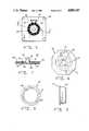
- FIG. 1is an elevational view of the switch assembly according to the present invention
- FIG. 2is a side view of the switch assembly of FIG. 1 taken from the left hand side thereof;
- FIG. 3is a side view of the switch assembly of FIG. 1 taken from the right hand side thereof;
- FIG. 4is a cross sectional view of the switch assembly of FIG. 1 taken along line 4--4 thereof;
- FIG. 5is a top plan view of the printed circuit board including the membrane switch assembly
- FIG. 6is a top plan view of the membrane for the membrane switch assembly of FIG. 5;
- FIG. 7is a cross sectional view of the printed circuit board and membrane switch assembly of FIG. 5;
- FIG. 8is an elevational view of the grommet for the switch assembly of FIG. 1;
- FIG. 9is a side view of the grommet of FIG. 8;
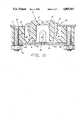
- FIG. 10is an enlarged cross sectional view of the switch assembly mounted on a panel.
- a switch assembly 10including a unitary elastomeric housing or body 12.
- the housingincludes a push button 14 which is integrally molded with a mounting base 16 and is connected to the mounting base 16 by means of a flexible web 18.
- the push buttonis hollow whereby a space 15 will be provided inside push button 14.
- a hollow space 20 of generally cylindrical shapesurrounds push button 14.
- Push button 14is therefore axially inwardly moveable into space 20 by flexing movement of web 18, as best seen in FIG. 4, by virtue of the flexibility of web 18.
- Mounting base 16includes four apertures 17, as best seen in FIG. 2, for mounting housing 12 on a panel, as further explained hereinafter.
- Housing 12is a unitary molding formed of a resilient elastomeric material such as silicone.
- This materialmay be molded to provide a resilient housing 12 whereby housing 12 may be sealingly clamped against a panel, whereby push button 14 may be depressed to actuate a switch, and whereby the connecting web 18 generates sufficient restoring force to return the push button 14 to its normal rest position as illustrated in FIG. 4.
- Web 18is connected to the mounting base 16 by means of a thicker portion 22. It can be seen that web 18 forms a frusto-conical portion which then tapers into a thicker portion 22.
- a sealing ring 24is also integrally molded on mounting base 16 for purposes further explained hereinafter.
- Push button 14includes an actuating ring portion 26 for actuating a switch as further explained hereinafter.
- a printed circuit board 28is captured between two flanges 30 which are integrally molded with housing 12 and retain circuit board 28 during shipment of switch assembly 10.
- Circuit board 28is made of conventional printed circuit board insulating material and has connected thereto four contact posts 32 by way of a contact header 34.
- Contact posts 32are soldered to islands (not shown) provided on circuit board 28.
- Contact header 34is formed of an insulating material, such as plastic material, and includes a contact header lock 36 for locking a connector to contact header 34.
- a pair of printed circuit board connecting tracks 38are also provided on circuit board 28. The tracks end in islands 40 to which the leads of an LED are soldered as disclosed hereinafter.
- a pair of apertures 42is provided in the circuit board whereby air may escape from space 20 when push button 14 is depressed.
- Circuit board 28includes four apertures 48 which are aligned with apertures 17 in mounting base 16 for receiving threaded mounting posts. It can also be seen that circuit board 28 is slightly smaller than the outside circumference of mounting base 16. However, the dimension of the circuit board 28 with respect to mounting base 16 is a matter of design choice.
- a switch 60which forms an integral part of circuit board 28.
- the face of circuit board 28 opposite to contact header 34is provided with two spaced apart, interlocking contact strips 62 and 64 which are so configured that they form a circle.
- Tracks 65connect the contact strips 62, 64 to soldering islands which in turn are connected by two through holes to two contact posts 32.
- a membrane 66having a central aperture 68 therein, is mounted over contact strips 62 and 64.
- Membrane 66is so configured, as shown in FIG. 6, that it fits within the confines of the printed circuit board and the mounting apertures 48.
- a ring-shaped metallic layer 70is deposited on membrane 66 for selectively providing an electrical connection between contact strips 62, 64 and selectively bridging those contact strips to close switch 60.
- Metallic contact ring 70is conventionally formed of silver oxide or other suitable conductive material.
- Membrane 66is formed of mylar or another insulative material having suitable flexibility so that metallic contact ring 70 is normally out of contact with contact strips 62, 64 as best shown in FIG. 7, but which, upon depression of the push button, will be sufficiently flexed so that the contact strips 62, 64 will be bridged and the switch 60 will be closed.
- a layer of adhesive material 72serves to both space the membrane 66 sufficiently far away from printed circuit board 28 and to adhere membrane 66 to printed circuit board 28.
- the adhesive 72is applied in a keyhole shaped pattern to avoid contact of the adhesive material with metallic contact ring 70 or tracks 65.
- contact strips 62, 64will be bridged, thereby causing switch 60 to close.
- Membrane 66being formed of rather stiff mylar, has sufficient rigidity to return to its rest position as shown in FIG. 7 when the push button actuator ring portion 26 moves out of contact with membrane 66.
- a grommet 80which includes a flange or bezel 82, a cylindrical rim 84 and an aperture 86.
- Rim 84is configured to fit in space 20 which surrounds push button 14.
- the material from which the bezel 82 is manufacturedmay be any suitable material but, in one embodiment, is molded of polypropylene material.
- the switch assembly 10 shown in FIG. 1is secured to a panel 90.
- the panelmay be the display panel of a fuel dispensing installation.
- Panel 90includes an aperture into which grommet 80 is inserted.
- Housing 12is so assembled to panel 90 so that cylindrical rim 84 is disposed in space 20.
- Circuit board 28is aligned with housing 12 whereby apertures 48 line up with apertures 17.
- Metallic studs 92are secured to panel 90 as by brazing and are disposed in apertures 17 and 48. The ends of the studs are threaded for receiving nuts 94. Washers 96 prevent the nuts from working loose.
- LED 44is energized at appropriate times to provide a signal to the operator. Signalling may be accomplished by either intermittent flashing or by constant energization of LED 44. The resiliency of web 18 will cause push button 14 to be returned to its rest position after pressure is removed from push button 14.
- grommet 80guides push button 14 for substantially axial movement so that push button 14 cannot wobble and therefore make insufficient or improper contact with membrane 66.
- grommet 80insures that the push button travels in a substantially linear path, when it is depressed, and that push button actuator ring portion 26 contacts membrane 66 in such fashion that contact ring 70 makes proper contact with contact strips 62 and 64.
Landscapes
- Push-Button Switches (AREA)
Abstract
Description
Claims (21)
Priority Applications (1)
| Application Number | Priority Date | Filing Date | Title |
|---|---|---|---|
| US07/277,302US4885443A (en) | 1988-11-29 | 1988-11-29 | Sealed backlit switch assembly |
Applications Claiming Priority (1)
| Application Number | Priority Date | Filing Date | Title |
|---|---|---|---|
| US07/277,302US4885443A (en) | 1988-11-29 | 1988-11-29 | Sealed backlit switch assembly |
Publications (1)
| Publication Number | Publication Date |
|---|---|
| US4885443Atrue US4885443A (en) | 1989-12-05 |
Family
ID=23060269
Family Applications (1)
| Application Number | Title | Priority Date | Filing Date |
|---|---|---|---|
| US07/277,302Expired - Fee RelatedUS4885443A (en) | 1988-11-29 | 1988-11-29 | Sealed backlit switch assembly |
Country Status (1)
| Country | Link |
|---|---|
| US (1) | US4885443A (en) |
Cited By (30)
| Publication number | Priority date | Publication date | Assignee | Title |
|---|---|---|---|---|
| US5138119A (en)* | 1991-03-15 | 1992-08-11 | Lucas Duralith Corporation | Backlit tactile keyboard with improved tactile and electrical characteristics |
| US5237327A (en)* | 1990-11-19 | 1993-08-17 | Sony Corporation | Remote commander |
| US5285037A (en)* | 1992-04-10 | 1994-02-08 | Ampex Systems Corp. | Illuminated dome switch |
| US5403984A (en)* | 1992-06-23 | 1995-04-04 | Yazaki Corporation | Rubber contact switch |
| US5552571A (en)* | 1991-04-23 | 1996-09-03 | Bodenseewerk Geratetechnik Gmbh | Push-button switch having a plurality of simultaneously closed contacts |
| US5826708A (en)* | 1997-01-29 | 1998-10-27 | Invotronics Manufacturing | Backlighted dome switch assembly |
| US5844203A (en)* | 1995-10-06 | 1998-12-01 | Black & Decker Inc. | Combined switch actuator and signal light transmitter for an iron |
| US5847336A (en)* | 1997-05-02 | 1998-12-08 | Telefonaktiebolaget L M Ericsson (Publ) | Direct keypad backlighting |
| US20020168948A1 (en)* | 2001-05-14 | 2002-11-14 | Nec Corporation | Portable communication unit |
| EP1267372A1 (en)* | 2001-06-15 | 2002-12-18 | GE Power Controls Italia S.p.a. | Integrated lighting units to be mounted on signalling and control devices for electric control boards and the like |
| US20040137966A1 (en)* | 1999-09-03 | 2004-07-15 | Matsushita Electric Industrial Co., Ltd. | Telephone terminal device |
| US20050168966A1 (en)* | 2001-12-21 | 2005-08-04 | Polymatech Co., Ltd. | Cover member for illuminated pushbutton switch |
| US20070074473A1 (en)* | 2005-08-31 | 2007-04-05 | Fujitsu Limited | Waterproof/drainage structure for a casing, and electronic devices |
| US20090047626A1 (en)* | 2007-08-13 | 2009-02-19 | Pelton & Crane | Touch-operated brake release for a delivery unit articulating arm |
| US20090047617A1 (en)* | 2007-08-13 | 2009-02-19 | Pelton & Crane | Multiple position hand-piece holster for a delivery unit |
| US7498538B1 (en) | 2007-07-20 | 2009-03-03 | Judco Manufacturing, Inc. | Sliding contact switch |
| US7514643B1 (en) | 2005-07-19 | 2009-04-07 | Judco Manufacturing, Inc. | Lighted pushbutton switch assembly |
| US20100084254A1 (en)* | 2008-10-07 | 2010-04-08 | Research In Motion Limited | Sealed dome switch for mobile electronic device |
| US7880107B1 (en) | 2007-10-12 | 2011-02-01 | Judco Manufacturing, Inc. | Momentary push button switch |
| US8178802B2 (en) | 2008-07-31 | 2012-05-15 | Electrolux Home Products, Inc. | Unitized appliance control panel assembly and components of the assembly |
| US20120152710A1 (en)* | 2010-12-21 | 2012-06-21 | Hon Hai Precision Industry Co., Ltd. | Power button and electronic device using same |
| WO2016055435A1 (en)* | 2014-10-08 | 2016-04-14 | Continental Automotive Gmbh | Actuating element with corona illumination |
| CN105679584A (en)* | 2016-04-19 | 2016-06-15 | 丹阳市光华汽车内饰件有限公司 | Button switch structure with indication function |
| US20180033573A1 (en)* | 2015-03-07 | 2018-02-01 | Audi Ag | Motor vehicle operating device with sound-generating switching element |
| US9984835B2 (en) | 2016-09-01 | 2018-05-29 | Banner Engineering Corp. | Impact absorbing unitary cover assembly |
| US10321970B1 (en)* | 2018-01-09 | 2019-06-18 | American Sterilizer Company | Handle assembly for a surgical lighting system |
| US10650988B2 (en) | 2018-01-09 | 2020-05-12 | American Sterilizer Company | Sterilizable handle actuating button integration |
| US11107648B2 (en)* | 2019-05-28 | 2021-08-31 | Google Llc | Button with illumination ring |
| USD977352S1 (en)* | 2017-11-30 | 2023-02-07 | Carrier Corporation | Notification appliance |
| WO2023098069A1 (en)* | 2021-11-30 | 2023-06-08 | 华为技术有限公司 | Key structure and wearable device |
Citations (15)
| Publication number | Priority date | Publication date | Assignee | Title |
|---|---|---|---|---|
| US2343060A (en)* | 1941-09-25 | 1944-02-29 | Gen Motors Corp | Switch |
| US2562185A (en)* | 1949-03-03 | 1951-07-31 | Clarence D Gross | Push-button switch |
| US3663781A (en)* | 1970-11-23 | 1972-05-16 | Scm Corp | Electrical switch having a flexible one-piece actuator |
| US3735068A (en)* | 1970-09-26 | 1973-05-22 | Alps Electric Co Ltd | Push-button switch with resilient conductive contact member and with helical conductive networks |
| US4056701A (en)* | 1976-07-08 | 1977-11-01 | Bowmar Instrument Corporation | Low profile lighted push button switch |
| US4088855A (en)* | 1977-02-28 | 1978-05-09 | Korry Manufacturing Co. | Keyboard electro-mechanical switch with coil spring contact |
| US4117279A (en)* | 1977-05-20 | 1978-09-26 | Motorola, Inc. | Modular pushbutton keyset assembly |
| US4121070A (en)* | 1977-03-04 | 1978-10-17 | Renal Systems, Inc. | Enclosed push button type switch |
| US4360722A (en)* | 1980-11-03 | 1982-11-23 | Gte Automatic Electric Labs Inc. | Designation cap actuator assembly |
| US4463232A (en)* | 1982-06-10 | 1984-07-31 | Toho- Polymer Kabushiki Kaisha | Membrane switch having spacer posts |
| US4471189A (en)* | 1981-09-01 | 1984-09-11 | La Telemecanique Electrique | Sealed, modular keyboard providing a tactile feel |
| US4491702A (en)* | 1982-02-01 | 1985-01-01 | Sun Arrow Koeki Company Ltd. | Key-top panel and keyboard structure using the panel |
| US4604509A (en)* | 1985-02-01 | 1986-08-05 | Honeywell Inc. | Elastomeric push button return element for providing enhanced tactile feedback |
| US4710597A (en)* | 1984-06-26 | 1987-12-01 | Tabur Caoutchouc | Keyboard for the control box of an electric apparatus |
| US4822963A (en)* | 1985-07-10 | 1989-04-18 | Adams Elevator Equipment Co. | Vandal resistant push button assembly |
- 1988
- 1988-11-29USUS07/277,302patent/US4885443A/ennot_activeExpired - Fee Related
Patent Citations (15)
| Publication number | Priority date | Publication date | Assignee | Title |
|---|---|---|---|---|
| US2343060A (en)* | 1941-09-25 | 1944-02-29 | Gen Motors Corp | Switch |
| US2562185A (en)* | 1949-03-03 | 1951-07-31 | Clarence D Gross | Push-button switch |
| US3735068A (en)* | 1970-09-26 | 1973-05-22 | Alps Electric Co Ltd | Push-button switch with resilient conductive contact member and with helical conductive networks |
| US3663781A (en)* | 1970-11-23 | 1972-05-16 | Scm Corp | Electrical switch having a flexible one-piece actuator |
| US4056701A (en)* | 1976-07-08 | 1977-11-01 | Bowmar Instrument Corporation | Low profile lighted push button switch |
| US4088855A (en)* | 1977-02-28 | 1978-05-09 | Korry Manufacturing Co. | Keyboard electro-mechanical switch with coil spring contact |
| US4121070A (en)* | 1977-03-04 | 1978-10-17 | Renal Systems, Inc. | Enclosed push button type switch |
| US4117279A (en)* | 1977-05-20 | 1978-09-26 | Motorola, Inc. | Modular pushbutton keyset assembly |
| US4360722A (en)* | 1980-11-03 | 1982-11-23 | Gte Automatic Electric Labs Inc. | Designation cap actuator assembly |
| US4471189A (en)* | 1981-09-01 | 1984-09-11 | La Telemecanique Electrique | Sealed, modular keyboard providing a tactile feel |
| US4491702A (en)* | 1982-02-01 | 1985-01-01 | Sun Arrow Koeki Company Ltd. | Key-top panel and keyboard structure using the panel |
| US4463232A (en)* | 1982-06-10 | 1984-07-31 | Toho- Polymer Kabushiki Kaisha | Membrane switch having spacer posts |
| US4710597A (en)* | 1984-06-26 | 1987-12-01 | Tabur Caoutchouc | Keyboard for the control box of an electric apparatus |
| US4604509A (en)* | 1985-02-01 | 1986-08-05 | Honeywell Inc. | Elastomeric push button return element for providing enhanced tactile feedback |
| US4822963A (en)* | 1985-07-10 | 1989-04-18 | Adams Elevator Equipment Co. | Vandal resistant push button assembly |
Cited By (41)
| Publication number | Priority date | Publication date | Assignee | Title |
|---|---|---|---|---|
| US5237327A (en)* | 1990-11-19 | 1993-08-17 | Sony Corporation | Remote commander |
| US5138119A (en)* | 1991-03-15 | 1992-08-11 | Lucas Duralith Corporation | Backlit tactile keyboard with improved tactile and electrical characteristics |
| US5552571A (en)* | 1991-04-23 | 1996-09-03 | Bodenseewerk Geratetechnik Gmbh | Push-button switch having a plurality of simultaneously closed contacts |
| US5285037A (en)* | 1992-04-10 | 1994-02-08 | Ampex Systems Corp. | Illuminated dome switch |
| US5403984A (en)* | 1992-06-23 | 1995-04-04 | Yazaki Corporation | Rubber contact switch |
| US5844203A (en)* | 1995-10-06 | 1998-12-01 | Black & Decker Inc. | Combined switch actuator and signal light transmitter for an iron |
| US5826708A (en)* | 1997-01-29 | 1998-10-27 | Invotronics Manufacturing | Backlighted dome switch assembly |
| US5847336A (en)* | 1997-05-02 | 1998-12-08 | Telefonaktiebolaget L M Ericsson (Publ) | Direct keypad backlighting |
| US20040137966A1 (en)* | 1999-09-03 | 2004-07-15 | Matsushita Electric Industrial Co., Ltd. | Telephone terminal device |
| US20020168948A1 (en)* | 2001-05-14 | 2002-11-14 | Nec Corporation | Portable communication unit |
| US7038152B2 (en)* | 2001-05-14 | 2006-05-02 | Nec Corporation | Portable communication unit |
| EP1267372A1 (en)* | 2001-06-15 | 2002-12-18 | GE Power Controls Italia S.p.a. | Integrated lighting units to be mounted on signalling and control devices for electric control boards and the like |
| US20050168966A1 (en)* | 2001-12-21 | 2005-08-04 | Polymatech Co., Ltd. | Cover member for illuminated pushbutton switch |
| US7005596B2 (en)* | 2001-12-21 | 2006-02-28 | Polymatech Co., Ltd. | Cover member for illuminated pushbutton switch |
| US7075024B2 (en) | 2001-12-21 | 2006-07-11 | Polymatech, Co., Ltd. | Cover member for illuminated pushbutton switch |
| US7514643B1 (en) | 2005-07-19 | 2009-04-07 | Judco Manufacturing, Inc. | Lighted pushbutton switch assembly |
| US20070074473A1 (en)* | 2005-08-31 | 2007-04-05 | Fujitsu Limited | Waterproof/drainage structure for a casing, and electronic devices |
| US7365281B2 (en)* | 2005-08-31 | 2008-04-29 | Fujitsu Limited | Waterproof/drainage structure for a casing, and electronic devices |
| US7498538B1 (en) | 2007-07-20 | 2009-03-03 | Judco Manufacturing, Inc. | Sliding contact switch |
| US20090047617A1 (en)* | 2007-08-13 | 2009-02-19 | Pelton & Crane | Multiple position hand-piece holster for a delivery unit |
| WO2009023239A1 (en)* | 2007-08-13 | 2009-02-19 | Dental Equipment, Llc, Dba Pelton & Crane | Touch-operated brake release for a delivery unit articulating arm |
| US20090047626A1 (en)* | 2007-08-13 | 2009-02-19 | Pelton & Crane | Touch-operated brake release for a delivery unit articulating arm |
| US7880107B1 (en) | 2007-10-12 | 2011-02-01 | Judco Manufacturing, Inc. | Momentary push button switch |
| US8178802B2 (en) | 2008-07-31 | 2012-05-15 | Electrolux Home Products, Inc. | Unitized appliance control panel assembly and components of the assembly |
| US20100084254A1 (en)* | 2008-10-07 | 2010-04-08 | Research In Motion Limited | Sealed dome switch for mobile electronic device |
| US8089017B2 (en)* | 2008-10-07 | 2012-01-03 | Research In Motion Limited | Sealed dome switch for mobile electronic device |
| US8507820B2 (en) | 2008-10-07 | 2013-08-13 | Research In Motion Limited | Sealed dome switch for mobile electronic device |
| US20120152710A1 (en)* | 2010-12-21 | 2012-06-21 | Hon Hai Precision Industry Co., Ltd. | Power button and electronic device using same |
| US8513555B2 (en)* | 2010-12-21 | 2013-08-20 | Fu Tai Hua Industry (Shenzhen) Co., Ltd. | Power button and electronic device using same |
| WO2016055435A1 (en)* | 2014-10-08 | 2016-04-14 | Continental Automotive Gmbh | Actuating element with corona illumination |
| US10276323B2 (en) | 2014-10-08 | 2019-04-30 | Continental Automotive Gmbh | Actuating element with corona illumination |
| US20180033573A1 (en)* | 2015-03-07 | 2018-02-01 | Audi Ag | Motor vehicle operating device with sound-generating switching element |
| US10163591B2 (en)* | 2015-03-07 | 2018-12-25 | Audi Ag | Motor vehicle operating device with sound-generating switching element |
| CN105679584A (en)* | 2016-04-19 | 2016-06-15 | 丹阳市光华汽车内饰件有限公司 | Button switch structure with indication function |
| US9984835B2 (en) | 2016-09-01 | 2018-05-29 | Banner Engineering Corp. | Impact absorbing unitary cover assembly |
| USD977352S1 (en)* | 2017-11-30 | 2023-02-07 | Carrier Corporation | Notification appliance |
| US10321970B1 (en)* | 2018-01-09 | 2019-06-18 | American Sterilizer Company | Handle assembly for a surgical lighting system |
| US10650988B2 (en) | 2018-01-09 | 2020-05-12 | American Sterilizer Company | Sterilizable handle actuating button integration |
| US11107648B2 (en)* | 2019-05-28 | 2021-08-31 | Google Llc | Button with illumination ring |
| US11404226B2 (en)* | 2019-05-28 | 2022-08-02 | Google Llc | Button with illumination ring |
| WO2023098069A1 (en)* | 2021-11-30 | 2023-06-08 | 华为技术有限公司 | Key structure and wearable device |
Similar Documents
| Publication | Publication Date | Title |
|---|---|---|
| US4885443A (en) | Sealed backlit switch assembly | |
| US7485824B2 (en) | Electrical switch component | |
| US4225766A (en) | Touch contact | |
| US4056701A (en) | Low profile lighted push button switch | |
| US5559311A (en) | Dual detent dome switch assembly | |
| US4360722A (en) | Designation cap actuator assembly | |
| EP0444914A2 (en) | Switch assembly | |
| US5626223A (en) | Cam-assisted switch | |
| GB2391110A (en) | Switch with pcb | |
| US6466140B1 (en) | Pedestrian push button assembly | |
| US6967296B2 (en) | Steering switch device | |
| US5285038A (en) | Lighted momentary push-button switch assembly having integral switch actuator and lamp locator | |
| HK99295A (en) | Self-retaining actuator assembly | |
| CA1236506A (en) | Limit switch assembly | |
| US4191871A (en) | Push-button assembly | |
| US7501594B2 (en) | Self contained actuator for refrigerator dispenser functions | |
| US4414452A (en) | Means for attaching auxiliary devices to a membrane switch | |
| US3944766A (en) | Seat belt buckle having pushbutton type switch with elastomeric conductor bridging contact | |
| EP1581957A1 (en) | Commutation device having an integrated light source | |
| GB2077506A (en) | Pushbutton switch for electronic timepieces | |
| US7009127B2 (en) | Switch comprising an operating rocker button | |
| GB2255232A (en) | Alarm call points | |
| JPH05234460A (en) | Keyboard switch | |
| JPS584411B2 (en) | Push button switch with lamp display | |
| EP0703591A1 (en) | Input/output device with a lamp and a switch having protection against electrostatic discharge and contamination |
Legal Events
| Date | Code | Title | Description |
|---|---|---|---|
| AS | Assignment | Owner name:TOKHEIM CORPORATION, INDIANA Free format text:ASSIGNMENT OF ASSIGNORS INTEREST.;ASSIGNORS:SIMCOE, STEVEN B.;ORTH, CHARLES M.;VAN DAELE, JOHN J.;REEL/FRAME:005029/0522 Effective date:19890201 | |
| FEPP | Fee payment procedure | Free format text:PAYOR NUMBER ASSIGNED (ORIGINAL EVENT CODE: ASPN); ENTITY STATUS OF PATENT OWNER: LARGE ENTITY | |
| AS | Assignment | Owner name:NBD BANK, N.A. Free format text:SECURITY INTEREST;ASSIGNORS:TOKHEIM CORPORATION, A CORP. OF IN;ENVIROTRONIC CORPORATION, A CORP. OF IN;TOKHEIM INVESTMENT CORP., A CORP. OF TX;AND OTHERS;REEL/FRAME:006167/0397 Effective date:19920529 | |
| REMI | Maintenance fee reminder mailed | ||
| LAPS | Lapse for failure to pay maintenance fees | ||
| FP | Lapsed due to failure to pay maintenance fee | Effective date:19931205 | |
| AS | Assignment | Owner name:TOKHEIM CORPORATION, INDIANA Free format text:RELEASE AND REASSIGNMENT;ASSIGNOR:NBD BANK, N.A.;REEL/FRAME:008178/0907 Effective date:19960906 | |
| AS | Assignment | Owner name:NBD BANK, N.A., INDIANA Free format text:SECURITY INTEREST;ASSIGNORS:TOKHEIM CORPORATION;TOKHEIM AUTOMATION CORPORATION;ENVIROTRONIC SYSTEM;AND OTHERS;REEL/FRAME:009490/0228 Effective date:19980930 | |
| AS | Assignment | Owner name:ABN AMRO BANK N.V., ILLINOIS Free format text:SECURITY AGREEMENT;ASSIGNOR:TOKHEIM CORPORTION;REEL/FRAME:012014/0756 Effective date:20001020 | |
| STCH | Information on status: patent discontinuation | Free format text:PATENT EXPIRED DUE TO NONPAYMENT OF MAINTENANCE FEES UNDER 37 CFR 1.362 |