US4885436A - Electronic module interlock and extraction mechanism - Google Patents
Electronic module interlock and extraction mechanismDownload PDFInfo
- Publication number
- US4885436A US4885436AUS07/238,006US23800688AUS4885436AUS 4885436 AUS4885436 AUS 4885436AUS 23800688 AUS23800688 AUS 23800688AUS 4885436 AUS4885436 AUS 4885436A
- Authority
- US
- United States
- Prior art keywords
- actuator
- switch
- module
- positions
- switch guard
- Prior art date
- Legal status (The legal status is an assumption and is not a legal conclusion. Google has not performed a legal analysis and makes no representation as to the accuracy of the status listed.)
- Expired - Lifetime
Links
- 230000007246mechanismEffects0.000titleclaimsabstractdescription36
- 238000000605extractionMethods0.000titleclaimsabstractdescription14
- 238000003780insertionMethods0.000claimsabstractdescription14
- 230000037431insertionEffects0.000claimsabstractdescription14
- 210000003811fingerAnatomy0.000claimsdescription9
- 210000003813thumbAnatomy0.000claimsdescription7
- 230000013011matingEffects0.000claimsdescription5
- 230000008878couplingEffects0.000claims1
- 238000010168coupling processMethods0.000claims1
- 238000005859coupling reactionMethods0.000claims1
- 230000000717retained effectEffects0.000claims1
- 230000004048modificationEffects0.000description2
- 238000012986modificationMethods0.000description2
- 230000009471actionEffects0.000description1
- 238000010276constructionMethods0.000description1
- 230000006872improvementEffects0.000description1
- 238000012423maintenanceMethods0.000description1
- 238000004519manufacturing processMethods0.000description1
- 239000013641positive controlSubstances0.000description1
- 230000003449preventive effectEffects0.000description1
- 230000001052transient effectEffects0.000description1
Images


Classifications
- H—ELECTRICITY
- H05—ELECTRIC TECHNIQUES NOT OTHERWISE PROVIDED FOR
- H05K—PRINTED CIRCUITS; CASINGS OR CONSTRUCTIONAL DETAILS OF ELECTRIC APPARATUS; MANUFACTURE OF ASSEMBLAGES OF ELECTRICAL COMPONENTS
- H05K7/00—Constructional details common to different types of electric apparatus
- H05K7/14—Mounting supporting structure in casing or on frame or rack
- H05K7/1401—Mounting supporting structure in casing or on frame or rack comprising clamping or extracting means
- H05K7/1414—Mounting supporting structure in casing or on frame or rack comprising clamping or extracting means with power interlock
Definitions
- This inventionrelates to devices for preventing the connection or disconnection of an electronic module from an electrical unit unless the power switch is off.
- the inventionrepresents an improvement over U.S. patent application Ser. No. 07/065,233, filed June 22, 1987, now U.S. Pat. No. 4,777,332, the disclosure of which is incorporated by reference.
- the inventionrelates to a switch interlock and extraction mechanism for an electronic module which permits connection and disconnection of the electrical connectors only when the main power switch is off and which simultaneously engages interlock surfaces on the unit to provide the initial and final driving force for the module as the electrical connectors are connected and disconnected.
- the inventionis, in one embodiment, used with a removable power supply module of the type used as a part of an electrical unit, such as a computer.
- the moduleis typically of the type having a rocker type power switch mounted to the front panel. Other types of power switches are also possible.
- a switch guardis also mounted to the front panel and moves between safe and working positions. The switch guard can be moved to the safe position only when the switch is off; once in the safe position the switch guard prevents the switch from being moved to its on position. When the switch guard is in its working position, the switch can be freely turned on and off.
- a combination interlock and extraction actuatoris also mounted to the front of the module and moves, preferably pivots, between insertion and retraction rotary positions.
- the actuatorhas two functions which are executed simultaneously. The first is the movement of the switch guard between its safe and working positions. The second is to move or drive the module during electrical connection and disconnection with the electrical unit.
- the actuatorhas a cam surface against which the switch guard rides.
- the actuatorWhen the module is being inserted into the unit, the actuator, is, just before the electrical connectors on the module and unit become engaged, moved in its insertion direction. As this occurs, the switch guard moves from its safe to its working position; simultaneously a latching element on the actuator engages a latching surface on the unit to drive the module until the connectors are fully connected.
- the switch actuatoris turned off and the cam actuator is moved in its retraction direction. This causes the switch guard to move into its safe position to prevent the switch actuator from being turned on; simultaneously the latching element on the actuator engages a disengagement surface on the unit to drive the module away from the unit thus disconnecting the electrical connectors.
- the switch guardis preferably spring biased against the camming surface of the actuator so to keep the actuator biased in its insertion direction. This helps to prevent inadvertent disconnection of the electrical connectors. This feature is especially useful to keep the electronic module fully engaged with the electrical unit even during transport.
- the inventionprovides a source of safety by keeping the user from inserting or withdrawing the module when the power switch actuator is on. Movement of the switch guard occurs simultaneously with the locking action of the latching element of the actuator engaging the interlock surface of the electrical unit so that the entire sequence occurs with one simple, preferably rotary, movement of the actuator.
- the actuatorpreferably includes a central finger opening and a radially extending thumb drive surface which aid the user in manipulating the actuator.
- the actuatorpermits the user to have positive control over both the rotary movement of the actuator and the movement of the electronic module into and out of the electrical unit. The invention thus eliminates the need for a separate handle which would otherwise be needed to pull the electronic module from the electrical unit and push the electronic module into the electrical unit.
- the modulemay be removed by simply first turning off the power switch actuator, and then rotating the cam actuator. Doing the latter both lifts the switch guard, to partially cover the toggle type power switch actuator, and simultaneously pulls the electronic module away from the electrical unit thus disconnecting the electrical connectors. Similarly, final insertion of the electronic module takes place with a single rotary motion of the actuator which simultaneously permits the switch guard plate to lower, thus exposing the switch, and engages the interlock surface of the electrical unit so to drive the electronic module into the electrical unit, thus mating the electrical connectors.
- the inventionis relatively simple in construction and requires very few modifications to existing electrical unit designs.
- the camming surfaceis configured to accommodate tolerance build up.
- the final portion of the camming surface, designed to contact the spring biased switch guard plate when the cam actuator has been fully rotated in the insertion rotary direction,is sized to take up any slack caused by tolerance build-up in both the electronic module and the electrical unit.
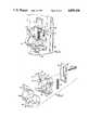
- FIG. 1is an isometric view showing the electronic module interlock and extraction mechanism mounted to an electronic module shown relative to an electrical unit with the power switch off.
- FIG. 2is an exploded isometric view of the interlock and extraction mechanism of FIG. 1.
- FIG. 3is a cross-sectional view of the interlock and extraction mechanism of FIG. 1 with the power switch on.
- FIGS. 4A and 4Bare simplified side views of the interlock and extraction mechanism of FIG. 1.
- the actuatoris rotated in the insertion direction and the switch guard is in the working position of FIG. 4A.
- the actuatoris rotated in the retraction direction and the switch guard is moved to its safe position in FIG. 4B.
- an electronic module interlock and extraction mechanism 2is shown used with an electronic module 4, such as a power supply, which is a part of an electrical unit 6, typically a computer.
- Module 4can be removed from unit 6, such as for servicing and preventive maintenance.
- a blind mateable electrical connector 8 of electronic module 4becomes disconnected from a mating electrical connector 10 of electrical unit 6.
- the toggle type power switch 12 mounted to the front panel 14 of electrical module 4is first switched to the off position of FIG. 1 from the on position of FIG. 3.
- Switch guard 16includes a cut-away portion 26 on its top edge 28 sized to slide over the bottom edge 30 of power switch 12 when switch 12 is off (see FIG. 1). Cut-away portion 26 is sized so it is blocked from upward movement by bottom edge 30 of switch 12 when the switch is on (see FIG. 3).
- Mechanism 2also includes a combination interlock and extraction actuator 34 pivotally mounted to a pair of extensions 36 of front panel 14 for movement about a pivot axis 38.
- actuator 34includes a cam surface 40 against which a lower surface 42 of switch guard 16 is biased by a coil spring 44.
- Spring 44is captured between an L-bracket 46 extending from front panel 14 and a lower shelf 48 of switch guard 16. Movement of actuator 34 in an insertion direction 50, see FIG. 4A, permits spring 44 to expand thus driving switch guard 16 to its lowered or wrking position shown in FIGS. 1, 3 and 4A.
- Rotating actuator 34 in the retraction direction 52see FIG. 4B, causes cam surface 40 to drive switch guard 16 to its upper or safe position of FIG.
- actuator 34can only be moved in retraction direction 52 when power switch 12 is in the off position, shown in solid lines in FIG. 4A. Once switch guard is in the safe position of FIG. 4B, power switch 12 cannot then be turned on.
- Electrical unit 6includes a C-shaped extension 56 having a pair of vertically extending latching or interlock surfaces 58, 60. Surfaces 58, 60 are engaged by a U-shaped latching element 62 of actuator 34. Element 62 has a pair of opposed portions 64, 66 which engage surfaces 58, 60 when actuator 34 is pivoted in retraction direction 52 and insertion direction 50 respectively.
- extension 56includes a cut-out 68, shown best in FIG. 3, to accommodate the lower portion 70 of actuator 34 when the actuator is rotated in insertion direction 50.
- actuator 34During reinsertion of module 4, actuator 34 must be substantially in the rotary orientation of FIG. 4B, thus ensuring the power switch 12 is off during reinsertion. If actuator 34 were in the rotary orientation of FIG. 4A and if one were to attempt to insert electronic module into electrical unit 6, lower portion 70 of actuator 34 would interfere with this by engaging C-shaped extension 56 thus preventing connection of electrical connectors 8, 10.
- Actuator 34includes a finger opening 74 and a radially extending thumb drive 76.
- Finger opening 74permits the user to obtain a good grasp on actuator 34 to aid pulling module 4 from electrical unit 6 and pushing the module into the electrical unit.
- Thumb drive 76provides a pair of surfaces 78, 80 against which the user's thumb may be placed when rotating actuator 34 in insertion direction 50 and retraction direction 52, respectively. The resulting structure creates the ability for substantially one-handed operation during insertion and retraction of module 4.
- pivot axis 38 and latching surface 60will often vary because of manufacturing tolerances. This affects when electrical connectors 8, 10 engage and disengage.
- cam surface 40includes a relatively long final surface portion 82 against which lower surface 42 rests when actuator 34 is in the working rotary orientation of FIG. 4A.
- Surface portion 82is long enough to accommodate a range of final rotary orientations of actuator 34 when electronic module is fully inserted within electrical unit 6 so that connectors 8, 10 are fully engaged.
- power switch 12is a toggle switch and switch guard 16 slides to cover one end 54 of the power switch when switch 12 is off.
- Power switcheshaving other types of movement, and corresponding appropriately configured switch guards, could also be used.
- actuator 34 and switch guard 16could be coupled in other manners, such as through a linkage arrangement.
- the present arrangementis relatively simple and effective both in its primary function of providing an interlocking extraction mechanism and also one of its secondary functions, that of helping to keep electronic module 4 fully engaged within electrical unit 6 by virtue of the spring bias of switch guard 16 against cam surface 40.
Landscapes
- Engineering & Computer Science (AREA)
- Microelectronics & Electronic Packaging (AREA)
- Mounting Of Printed Circuit Boards And The Like (AREA)
- Details Of Connecting Devices For Male And Female Coupling (AREA)
- Power Sources (AREA)
Abstract
Description
Claims (20)
Priority Applications (5)
| Application Number | Priority Date | Filing Date | Title |
|---|---|---|---|
| US07/238,006US4885436A (en) | 1988-08-29 | 1988-08-29 | Electronic module interlock and extraction mechanism |
| CA000608548ACA1319968C (en) | 1988-08-29 | 1989-08-16 | Electronic module interlock and extraction mechanism |
| EP19890308438EP0357308A3 (en) | 1988-08-29 | 1989-08-21 | Electronic module interlock and extraction mechanism |
| AU40280/89AAU622472B2 (en) | 1988-08-29 | 1989-08-25 | Electronic module interlock and extraction mechanism |
| JP1222787AJP2824087B2 (en) | 1988-08-29 | 1989-08-29 | Electronic module locking / extracting mechanism |
Applications Claiming Priority (1)
| Application Number | Priority Date | Filing Date | Title |
|---|---|---|---|
| US07/238,006US4885436A (en) | 1988-08-29 | 1988-08-29 | Electronic module interlock and extraction mechanism |
Publications (1)
| Publication Number | Publication Date |
|---|---|
| US4885436Atrue US4885436A (en) | 1989-12-05 |
Family
ID=22896094
Family Applications (1)
| Application Number | Title | Priority Date | Filing Date |
|---|---|---|---|
| US07/238,006Expired - LifetimeUS4885436A (en) | 1988-08-29 | 1988-08-29 | Electronic module interlock and extraction mechanism |
Country Status (5)
| Country | Link |
|---|---|
| US (1) | US4885436A (en) |
| EP (1) | EP0357308A3 (en) |
| JP (1) | JP2824087B2 (en) |
| AU (1) | AU622472B2 (en) |
| CA (1) | CA1319968C (en) |
Cited By (32)
| Publication number | Priority date | Publication date | Assignee | Title |
|---|---|---|---|---|
| US5148910A (en)* | 1991-03-19 | 1992-09-22 | Houston Industries Incorporated | Circuit breaker tagging/lockout apparatus |
| US5187646A (en)* | 1989-09-13 | 1993-02-16 | Mannesmann Kienzle Gmbh | Data storage device with an arrangement for receiving a transportable, card-shaped or disk-shaped data storage unit so that the data storage unit is inaccessible in an operating position |
| US5198627A (en)* | 1991-08-09 | 1993-03-30 | Tandem Computers Incorporated | Electronic module switch and power and interlock system |
| US5226828A (en)* | 1991-09-23 | 1993-07-13 | Siemens Aktiengesellschaft | Device for unlocking a resiliently prestressed catch element at the side of an insert unit |
| US5289347A (en)* | 1992-06-04 | 1994-02-22 | Digital Equipment Corporation | Enclosure for electronic modules |
| US5321962A (en)* | 1991-08-29 | 1994-06-21 | Ferchau Joerg U | Injector/ejector latch lock mechanism |
| US5410112A (en)* | 1994-02-08 | 1995-04-25 | Minnesota Mining And Manufacturing Company | Safety interlock for overhead projector |
| USD365547S (en) | 1994-11-14 | 1995-12-26 | Emed Company, Inc. | Lockout device for circuit breaker |
| DE29509603U1 (en)* | 1995-06-12 | 1996-07-11 | Siemens AG, 80333 München | Front system for a printed circuit board with active-passive switching |
| DE29509602U1 (en)* | 1995-06-12 | 1996-07-11 | Siemens AG, 80333 München | Front system of a flat module with an integrated button element for an active-passive circuit |
| US5641953A (en)* | 1995-03-20 | 1997-06-24 | C-Cor Electronics, Inc. | Safety interlock system for telecommunication amplifiers |
| US5925130A (en)* | 1996-07-18 | 1999-07-20 | Compaq Computer Corporation | Computer power switch interlock |
| US5940276A (en)* | 1995-06-12 | 1999-08-17 | Siemens Aktiengesellschaft | Front system of a printed circuit board assembly having an integrated push-button element for active-passive switching |
| US5949652A (en)* | 1997-10-24 | 1999-09-07 | Dell U.S.A., L.P. | Computer power supply insertion and extraction apparatus and method |
| US5959843A (en)* | 1995-06-12 | 1999-09-28 | Siemens Aktiengesellschaft | Front system for a printed circuit board assembly having active-passive switching |
| US6207909B1 (en)* | 1997-10-27 | 2001-03-27 | Transistor Devices, Inc. | Latching handle mechanism for securing a module |
| DE20014199U1 (en)* | 2000-08-17 | 2001-10-04 | Siemens AG, 80333 München | Actuating element for levering in and out of flat assemblies with display element in the actuating lever, front element for a flat assembly with actuating element and subrack for accommodating flat assemblies |
| DE20014198U1 (en)* | 2000-08-17 | 2001-10-04 | Siemens AG, 80333 München | Front system for a printed circuit board with integrated electrical display element and lever pull handle with an end piece for a front system |
| DE20014196U1 (en)* | 2000-08-17 | 2001-10-04 | Siemens AG, 80333 München | Actuating element for levering in and levering out printed circuit boards with combined display / switching element in the operating lever, front element for a printed circuit board with operating element and subrack for accepting printed circuit boards |
| DE20014195U1 (en)* | 2000-08-17 | 2001-10-04 | Siemens AG, 80333 München | Actuating element for levering in and out of printed circuit boards with locking element in at least three switch positions, front element for a printed circuit board with operating element and subrack for receiving printed circuit boards |
| DE10052622C1 (en)* | 2000-10-24 | 2002-08-14 | Abb Patent Gmbh | Device for locking a pluggable electrical unit |
| US6515866B2 (en)* | 1998-12-23 | 2003-02-04 | Elma Electronic Ag | Plug module with active-passive switching |
| US6670729B2 (en)* | 2001-05-03 | 2003-12-30 | Pluris, Inc. | Intelligent circuit breaker module |
| US6693502B2 (en)* | 2000-12-01 | 2004-02-17 | Lg Industrial Systems Co., Ltd. | Air circuit breaker |
| US20040253068A1 (en)* | 2000-08-14 | 2004-12-16 | Graham Gerhardt | Electric power tool |
| US20050088825A1 (en)* | 2003-10-22 | 2005-04-28 | Hewlett-Packard Development Company, L.P. | Computing device module |
| US20080146061A1 (en)* | 2006-12-19 | 2008-06-19 | International Business Machines Corporation | Method Of Locking And Activating A Hot Swappable Daughter Card |
| US20100193337A1 (en)* | 2005-01-31 | 2010-08-05 | Solita Software Llc | Systems and methods for controlling operation of electronic devices |
| US8953332B2 (en) | 2012-04-10 | 2015-02-10 | International Business Machines Corporation | Positive pressure-applying compliant latch mechanism |
| US9433119B2 (en) | 2014-02-12 | 2016-08-30 | International Business Machines Corporation | Positive pressure-applying latch mechanism |
| US11027366B2 (en) | 2016-08-26 | 2021-06-08 | Nlight, Inc. | Laser power distribution module |
| CN114207957A (en)* | 2020-02-10 | 2022-03-18 | 华为数字能源技术有限公司 | Pluggable module |
Families Citing this family (5)
| Publication number | Priority date | Publication date | Assignee | Title |
|---|---|---|---|---|
| DE9012143U1 (en)* | 1990-08-23 | 1990-10-25 | Knürr-Mechanik für die Elektronik AG, 8000 München | Plugging and unplugging aid |
| JPH07321482A (en)* | 1994-05-24 | 1995-12-08 | Nec Corp | Anti-falling mechanism for power supply unit |
| DE10330260B4 (en)* | 2003-07-04 | 2007-04-05 | Siemens Ag | Safety-related locking of an electrical module at two attachment points |
| EP1524889B1 (en)* | 2003-10-13 | 2007-03-07 | Siemens Aktiengesellschaft | Fastening device of replaceable terminal or electronic modules with integrated quick disconnnecting system |
| US9910467B2 (en) | 2015-05-01 | 2018-03-06 | International Business Machines Corporation | Lid and power supply interlock mechanism |
Citations (15)
| Publication number | Priority date | Publication date | Assignee | Title |
|---|---|---|---|---|
| US2300102A (en)* | 1941-01-04 | 1942-10-27 | Colt S Mfg Co | Cover interlock for electrical casings |
| US2832857A (en)* | 1954-03-15 | 1958-04-29 | Wadsworth Electric Mfg Co | Locking plate for circuit breakers, switches and the like |
| US3109899A (en)* | 1960-10-18 | 1963-11-05 | Cutler Hammer Inc | Handle lock |
| US3801757A (en)* | 1972-08-02 | 1974-04-02 | Hubbell Inc Harvey | Heavy duty connector |
| US3919507A (en)* | 1974-04-23 | 1975-11-11 | Modicon Corp | Safety interlock for power switch of interconnected units |
| US4071722A (en)* | 1976-08-31 | 1978-01-31 | Bell Telephone Laboratories, Incorporated | Latch and switch interlock safety structure |
| US4158116A (en)* | 1977-10-25 | 1979-06-12 | Gould Inc. | Snap-on handle blocking device |
| US4276458A (en)* | 1978-11-06 | 1981-06-30 | Metzenauer & Jung Gmbh | Switch arrangement with switch contacts which can be changed as desired to normally open or normally closed operation |
| US4300030A (en)* | 1979-12-17 | 1981-11-10 | Gould Inc. | Handle blocking means for circuit breaker |
| US4435624A (en)* | 1982-09-23 | 1984-03-06 | Challenger Caribbean Corporation | Lock off-lock on |
| US4467152A (en)* | 1983-05-18 | 1984-08-21 | The United States Of America As Represented By The United States Department Of Energy | Circuit breaker lock out assembly |
| US4468544A (en)* | 1983-07-25 | 1984-08-28 | Anamae Wainess | Switch lock |
| US4563552A (en)* | 1983-02-08 | 1986-01-07 | Canon Kabushiki Kaisha | Electronic apparatus for controlling mechanical and electrical connection to memory means |
| US4596907A (en)* | 1984-04-30 | 1986-06-24 | At&T Bell Laboratories | Combination switch/latch for controlling circuit module/energization while securing module to support housing |
| US4777332A (en)* | 1987-06-22 | 1988-10-11 | Tandem Computers Incorporated | Apparatus for controlling the connection of an electrical module to an electrical receptacle |
Family Cites Families (3)
| Publication number | Priority date | Publication date | Assignee | Title |
|---|---|---|---|---|
| US3932716A (en)* | 1974-07-15 | 1976-01-13 | Bell Telephone Laboratories, Incorporated | Latch and switch actuator interlock safety structure for electronic component module operable during insertion and removal of connector members |
| EP0038583B1 (en)* | 1980-04-21 | 1984-05-09 | BBC Aktiengesellschaft Brown, Boveri & Cie. | Locking device for a switch mounted in a unit carrier withdrawable from a housing |
| US4716495A (en)* | 1986-09-22 | 1987-12-29 | Allen-Bradley Company, Inc. | Printer circuit board chassis with power interlock |
- 1988
- 1988-08-29USUS07/238,006patent/US4885436A/ennot_activeExpired - Lifetime
- 1989
- 1989-08-16CACA000608548Apatent/CA1319968C/ennot_activeExpired - Fee Related
- 1989-08-21EPEP19890308438patent/EP0357308A3/ennot_activeWithdrawn
- 1989-08-25AUAU40280/89Apatent/AU622472B2/ennot_activeCeased
- 1989-08-29JPJP1222787Apatent/JP2824087B2/ennot_activeExpired - Fee Related
Patent Citations (15)
| Publication number | Priority date | Publication date | Assignee | Title |
|---|---|---|---|---|
| US2300102A (en)* | 1941-01-04 | 1942-10-27 | Colt S Mfg Co | Cover interlock for electrical casings |
| US2832857A (en)* | 1954-03-15 | 1958-04-29 | Wadsworth Electric Mfg Co | Locking plate for circuit breakers, switches and the like |
| US3109899A (en)* | 1960-10-18 | 1963-11-05 | Cutler Hammer Inc | Handle lock |
| US3801757A (en)* | 1972-08-02 | 1974-04-02 | Hubbell Inc Harvey | Heavy duty connector |
| US3919507A (en)* | 1974-04-23 | 1975-11-11 | Modicon Corp | Safety interlock for power switch of interconnected units |
| US4071722A (en)* | 1976-08-31 | 1978-01-31 | Bell Telephone Laboratories, Incorporated | Latch and switch interlock safety structure |
| US4158116A (en)* | 1977-10-25 | 1979-06-12 | Gould Inc. | Snap-on handle blocking device |
| US4276458A (en)* | 1978-11-06 | 1981-06-30 | Metzenauer & Jung Gmbh | Switch arrangement with switch contacts which can be changed as desired to normally open or normally closed operation |
| US4300030A (en)* | 1979-12-17 | 1981-11-10 | Gould Inc. | Handle blocking means for circuit breaker |
| US4435624A (en)* | 1982-09-23 | 1984-03-06 | Challenger Caribbean Corporation | Lock off-lock on |
| US4563552A (en)* | 1983-02-08 | 1986-01-07 | Canon Kabushiki Kaisha | Electronic apparatus for controlling mechanical and electrical connection to memory means |
| US4467152A (en)* | 1983-05-18 | 1984-08-21 | The United States Of America As Represented By The United States Department Of Energy | Circuit breaker lock out assembly |
| US4468544A (en)* | 1983-07-25 | 1984-08-28 | Anamae Wainess | Switch lock |
| US4596907A (en)* | 1984-04-30 | 1986-06-24 | At&T Bell Laboratories | Combination switch/latch for controlling circuit module/energization while securing module to support housing |
| US4777332A (en)* | 1987-06-22 | 1988-10-11 | Tandem Computers Incorporated | Apparatus for controlling the connection of an electrical module to an electrical receptacle |
Cited By (47)
| Publication number | Priority date | Publication date | Assignee | Title |
|---|---|---|---|---|
| US5187646A (en)* | 1989-09-13 | 1993-02-16 | Mannesmann Kienzle Gmbh | Data storage device with an arrangement for receiving a transportable, card-shaped or disk-shaped data storage unit so that the data storage unit is inaccessible in an operating position |
| US5148910A (en)* | 1991-03-19 | 1992-09-22 | Houston Industries Incorporated | Circuit breaker tagging/lockout apparatus |
| US5198627A (en)* | 1991-08-09 | 1993-03-30 | Tandem Computers Incorporated | Electronic module switch and power and interlock system |
| US5321962A (en)* | 1991-08-29 | 1994-06-21 | Ferchau Joerg U | Injector/ejector latch lock mechanism |
| US5226828A (en)* | 1991-09-23 | 1993-07-13 | Siemens Aktiengesellschaft | Device for unlocking a resiliently prestressed catch element at the side of an insert unit |
| US5289347A (en)* | 1992-06-04 | 1994-02-22 | Digital Equipment Corporation | Enclosure for electronic modules |
| US5410112A (en)* | 1994-02-08 | 1995-04-25 | Minnesota Mining And Manufacturing Company | Safety interlock for overhead projector |
| USD365547S (en) | 1994-11-14 | 1995-12-26 | Emed Company, Inc. | Lockout device for circuit breaker |
| US5641953A (en)* | 1995-03-20 | 1997-06-24 | C-Cor Electronics, Inc. | Safety interlock system for telecommunication amplifiers |
| DE29509603U1 (en)* | 1995-06-12 | 1996-07-11 | Siemens AG, 80333 München | Front system for a printed circuit board with active-passive switching |
| DE29509602U1 (en)* | 1995-06-12 | 1996-07-11 | Siemens AG, 80333 München | Front system of a flat module with an integrated button element for an active-passive circuit |
| US5940276A (en)* | 1995-06-12 | 1999-08-17 | Siemens Aktiengesellschaft | Front system of a printed circuit board assembly having an integrated push-button element for active-passive switching |
| US5959843A (en)* | 1995-06-12 | 1999-09-28 | Siemens Aktiengesellschaft | Front system for a printed circuit board assembly having active-passive switching |
| US6128198A (en)* | 1995-06-12 | 2000-10-03 | Siemens Aktiengesellschaft | Front system for a printed circuit board assembly having active-passive switching |
| US5925130A (en)* | 1996-07-18 | 1999-07-20 | Compaq Computer Corporation | Computer power switch interlock |
| US5949652A (en)* | 1997-10-24 | 1999-09-07 | Dell U.S.A., L.P. | Computer power supply insertion and extraction apparatus and method |
| US6207909B1 (en)* | 1997-10-27 | 2001-03-27 | Transistor Devices, Inc. | Latching handle mechanism for securing a module |
| US6515866B2 (en)* | 1998-12-23 | 2003-02-04 | Elma Electronic Ag | Plug module with active-passive switching |
| US20040253068A1 (en)* | 2000-08-14 | 2004-12-16 | Graham Gerhardt | Electric power tool |
| US6896454B2 (en)* | 2000-08-14 | 2005-05-24 | Hills Industries Limited | Electric power tool |
| DE20014196U1 (en)* | 2000-08-17 | 2001-10-04 | Siemens AG, 80333 München | Actuating element for levering in and levering out printed circuit boards with combined display / switching element in the operating lever, front element for a printed circuit board with operating element and subrack for accepting printed circuit boards |
| DE20014195U1 (en)* | 2000-08-17 | 2001-10-04 | Siemens AG, 80333 München | Actuating element for levering in and out of printed circuit boards with locking element in at least three switch positions, front element for a printed circuit board with operating element and subrack for receiving printed circuit boards |
| DE20014199U1 (en)* | 2000-08-17 | 2001-10-04 | Siemens AG, 80333 München | Actuating element for levering in and out of flat assemblies with display element in the actuating lever, front element for a flat assembly with actuating element and subrack for accommodating flat assemblies |
| US20030221857A1 (en)* | 2000-08-17 | 2003-12-04 | Werner Koerber | Front system comprising and intergrated eletric display element |
| US7142432B2 (en) | 2000-08-17 | 2006-11-28 | Rittal Electronic Systems Gmbh & Co. Kg | Operating lever with display element |
| DE20014198U1 (en)* | 2000-08-17 | 2001-10-04 | Siemens AG, 80333 München | Front system for a printed circuit board with integrated electrical display element and lever pull handle with an end piece for a front system |
| US20040049903A1 (en)* | 2000-08-17 | 2004-03-18 | Werner Koerber | Operating lever with display element |
| US6924430B2 (en) | 2000-08-17 | 2005-08-02 | Rittal Electronics Systems Gmbh & Co. Kg | Actuating element comprising a locking element for inserting and removing flat modules by leverage in a least three connection positions, front element for a flat module, comprising an actuating element and a subassembly support for receiving flat modules |
| US20040099072A1 (en)* | 2000-08-17 | 2004-05-27 | Werner Koerber | Actuating element comprising a locking element for inserting and removing flat modules by leverage in at least three connection positions, front element for a flat module, comprisng an actuating element and a subassembly support for receiving flat modules |
| DE10052622C1 (en)* | 2000-10-24 | 2002-08-14 | Abb Patent Gmbh | Device for locking a pluggable electrical unit |
| US6693502B2 (en)* | 2000-12-01 | 2004-02-17 | Lg Industrial Systems Co., Ltd. | Air circuit breaker |
| EP1451839A4 (en)* | 2001-05-03 | 2004-10-06 | Pluris Inc | Intelligent circuit breaker module |
| WO2002091414A3 (en)* | 2001-05-03 | 2004-05-13 | Pluris Inc | Intelligent circuit breaker module |
| US6670729B2 (en)* | 2001-05-03 | 2003-12-30 | Pluris, Inc. | Intelligent circuit breaker module |
| US7199491B2 (en)* | 2001-05-03 | 2007-04-03 | Pluris, Inc. | Intelligent circuit breaker module |
| US20050088825A1 (en)* | 2003-10-22 | 2005-04-28 | Hewlett-Packard Development Company, L.P. | Computing device module |
| US7379303B2 (en)* | 2003-10-22 | 2008-05-27 | Hewlett-Packard Development Company, L.P. | Computing device module |
| US20100193337A1 (en)* | 2005-01-31 | 2010-08-05 | Solita Software Llc | Systems and methods for controlling operation of electronic devices |
| US7438577B2 (en) | 2006-12-19 | 2008-10-21 | International Business Machines Corporation | Method of locking and activating a hot swappable daughter card |
| US20080146061A1 (en)* | 2006-12-19 | 2008-06-19 | International Business Machines Corporation | Method Of Locking And Activating A Hot Swappable Daughter Card |
| US8953332B2 (en) | 2012-04-10 | 2015-02-10 | International Business Machines Corporation | Positive pressure-applying compliant latch mechanism |
| US9433119B2 (en) | 2014-02-12 | 2016-08-30 | International Business Machines Corporation | Positive pressure-applying latch mechanism |
| US9585284B2 (en) | 2014-02-12 | 2017-02-28 | International Business Machines Corporation | Fabrication of positive pressure-applying latch mechanism |
| US9943004B2 (en) | 2014-02-12 | 2018-04-10 | International Business Machines Corporation | Positive pressure-applying latch mechanism |
| US9949399B2 (en) | 2014-02-12 | 2018-04-17 | International Business Machines Corporation | Positive pressure-applying latch mechanism |
| US11027366B2 (en) | 2016-08-26 | 2021-06-08 | Nlight, Inc. | Laser power distribution module |
| CN114207957A (en)* | 2020-02-10 | 2022-03-18 | 华为数字能源技术有限公司 | Pluggable module |
Also Published As
| Publication number | Publication date |
|---|---|
| AU622472B2 (en) | 1992-04-09 |
| EP0357308A3 (en) | 1991-01-09 |
| EP0357308A2 (en) | 1990-03-07 |
| JP2824087B2 (en) | 1998-11-11 |
| AU4028089A (en) | 1990-03-01 |
| CA1319968C (en) | 1993-07-06 |
| JPH02121396A (en) | 1990-05-09 |
Similar Documents
| Publication | Publication Date | Title |
|---|---|---|
| US4885436A (en) | Electronic module interlock and extraction mechanism | |
| EP0390359B1 (en) | Electric module latch assembly | |
| CN100470952C (en) | Cable Connector Latch Assemblies | |
| US6418027B1 (en) | Programmable logic controller module assembly and locking system | |
| US7753711B2 (en) | Apparatus for plug-in and plug-out protection | |
| CA2138075C (en) | Automatic secondary disconnect | |
| US6545859B2 (en) | Automatically operating interlock assembly for electrical cabinets | |
| EP1100160B1 (en) | Electrical connector assembly with improved camming system | |
| US6388868B1 (en) | Automatically operating interlock assembly requiring an electrical cabinet to be closed before connection of the equipment therein | |
| US6746264B1 (en) | Pull type latch mechanism for removable small form factor electronic modules | |
| PL199119B1 (en) | Low voltage switchgear comprising a locking device for an appliance module | |
| US5902145A (en) | Connector quick coupling/decoupling mechanism | |
| US6445570B1 (en) | Automatically operating interlock assembly requiring an electrical cabinet to be closed before connection of the equipment | |
| US6519160B1 (en) | Pull type latch mechanism for removable small form factor electronic modules | |
| KR20230049548A (en) | Connector device | |
| US6293813B1 (en) | Electrical connector with latching backplate assembly | |
| US5688134A (en) | IC card connector apparatus | |
| US5691518A (en) | Sliding trigger interlock and secondary disconnect contacts for drawout switches | |
| MXPA96004753A (en) | Sliding trigger block | |
| US4268729A (en) | Plug and receptacle interlock | |
| JP7455095B2 (en) | Safety device for power supply modules applied to medium and high voltage systems | |
| EP0971454B1 (en) | Electrical connector with actuating device | |
| CN219436494U (en) | Drawer for a switchgear cabinet and switchgear cabinet | |
| EP4340138A1 (en) | Secured high power connector assembly and process of assembly | |
| KR20010091334A (en) | Eject lever locking structure of printed circuit board unit apply to communication device |
Legal Events
| Date | Code | Title | Description |
|---|---|---|---|
| AS | Assignment | Owner name:TANDEM COMPUTERS INCORPORATED, 19333 VALLCO PARKWA Free format text:ASSIGNMENT OF ASSIGNORS INTEREST.;ASSIGNORS:PHAM, HOA;MAX, ROBERT C.;REEL/FRAME:004976/0690 Effective date:19881026 | |
| STCF | Information on status: patent grant | Free format text:PATENTED CASE | |
| FEPP | Fee payment procedure | Free format text:PAYOR NUMBER ASSIGNED (ORIGINAL EVENT CODE: ASPN); ENTITY STATUS OF PATENT OWNER: LARGE ENTITY | |
| FPAY | Fee payment | Year of fee payment:4 | |
| FPAY | Fee payment | Year of fee payment:8 | |
| REMI | Maintenance fee reminder mailed | ||
| FPAY | Fee payment | Year of fee payment:12 | |
| AS | Assignment | Owner name:COMPAQ COMPUTER CORPORATION, A DELAWARE CORPORATIO Free format text:MERGER;ASSIGNOR:TANDEM COMPUTERS INCORPORATED;REEL/FRAME:014506/0598 Effective date:19981231 Owner name:COMPAQ INFORMATION TECHNOLOGIES GROUP, L.P., A TEX Free format text:ASSIGNMENT OF ASSIGNORS INTEREST;ASSIGNOR:COMPAQ COMPUTER CORPORATION;REEL/FRAME:014506/0133 Effective date:20010531 Owner name:HEWLETT-PACKARD DEVELOPMENT COMPANY, L.P., TEXAS Free format text:CHANGE OF NAME;ASSIGNOR:COMPAQ INFORMATION TECHNOLOGIES GROUP, L.P.;REEL/FRAME:014428/0584 Effective date:20021001 |