US4884506A - Remote detonation of explosive charges - Google Patents
Remote detonation of explosive chargesDownload PDFInfo
- Publication number
- US4884506A US4884506AUS06/927,362US92736286AUS4884506AUS 4884506 AUS4884506 AUS 4884506AUS 92736286 AUS92736286 AUS 92736286AUS 4884506 AUS4884506 AUS 4884506A
- Authority
- US
- United States
- Prior art keywords
- command
- control unit
- unit
- charge
- status
- Prior art date
- Legal status (The legal status is an assumption and is not a legal conclusion. Google has not performed a legal analysis and makes no representation as to the accuracy of the status listed.)
- Expired - Lifetime
Links
- 239000002360explosiveSubstances0.000titleclaimsabstractdescription41
- 238000005474detonationMethods0.000titleclaimsabstractdescription16
- 238000005422blastingMethods0.000claimsdescription22
- 238000000034methodMethods0.000claimsdescription13
- 230000005611electricityEffects0.000claimsdescription10
- 230000008859changeEffects0.000claimsdescription9
- 230000005540biological transmissionEffects0.000claimsdescription8
- 238000012790confirmationMethods0.000claimsdescription6
- 230000005672electromagnetic fieldEffects0.000claimsdescription5
- 230000004044responseEffects0.000claimsdescription5
- 230000008878couplingEffects0.000claims2
- 238000010168coupling processMethods0.000claims2
- 238000005859coupling reactionMethods0.000claims2
- 230000005670electromagnetic radiationEffects0.000claims1
- 230000001939inductive effectEffects0.000claims1
- 239000004020conductorSubstances0.000abstractdescription13
- 230000003287optical effectEffects0.000abstractdescription3
- 238000000926separation methodMethods0.000abstract1
- 238000010304firingMethods0.000description12
- 238000010586diagramMethods0.000description5
- 230000007246mechanismEffects0.000description5
- 239000003990capacitorSubstances0.000description4
- 230000000007visual effectEffects0.000description4
- 230000004913activationEffects0.000description3
- 239000012190activatorSubstances0.000description3
- 230000000694effectsEffects0.000description3
- 230000000977initiatory effectEffects0.000description3
- 239000003999initiatorSubstances0.000description2
- 230000003993interactionEffects0.000description2
- 230000005855radiationEffects0.000description2
- 230000009471actionEffects0.000description1
- 230000003213activating effectEffects0.000description1
- 230000008901benefitEffects0.000description1
- 238000010276constructionMethods0.000description1
- 238000007796conventional methodMethods0.000description1
- 230000001419dependent effectEffects0.000description1
- 238000013461designMethods0.000description1
- 230000007613environmental effectEffects0.000description1
- 238000004880explosionMethods0.000description1
- 238000005562fadingMethods0.000description1
- 239000007789gasSubstances0.000description1
- 238000010438heat treatmentMethods0.000description1
- 239000003550markerSubstances0.000description1
- 239000013307optical fiberSubstances0.000description1
- 230000008569processEffects0.000description1
- 239000000779smokeSubstances0.000description1
- 239000007787solidSubstances0.000description1
- 230000001360synchronised effectEffects0.000description1
Images


Classifications
- F—MECHANICAL ENGINEERING; LIGHTING; HEATING; WEAPONS; BLASTING
- F42—AMMUNITION; BLASTING
- F42C—AMMUNITION FUZES; ARMING OR SAFETY MEANS THEREFOR
- F42C11/00—Electric fuzes
- F42C11/06—Electric fuzes with time delay by electric circuitry
- F—MECHANICAL ENGINEERING; LIGHTING; HEATING; WEAPONS; BLASTING
- F42—AMMUNITION; BLASTING
- F42C—AMMUNITION FUZES; ARMING OR SAFETY MEANS THEREFOR
- F42C13/00—Proximity fuzes; Fuzes for remote detonation
- F42C13/04—Proximity fuzes; Fuzes for remote detonation operated by radio waves
- F—MECHANICAL ENGINEERING; LIGHTING; HEATING; WEAPONS; BLASTING
- F42—AMMUNITION; BLASTING
- F42C—AMMUNITION FUZES; ARMING OR SAFETY MEANS THEREFOR
- F42C15/00—Arming-means in fuzes; Safety means for preventing premature detonation of fuzes or charges
- F42C15/40—Arming-means in fuzes; Safety means for preventing premature detonation of fuzes or charges wherein the safety or arming action is effected electrically
- F42C15/42—Arming-means in fuzes; Safety means for preventing premature detonation of fuzes or charges wherein the safety or arming action is effected electrically from a remote location, e.g. for controlled mines or mine fields
- F—MECHANICAL ENGINEERING; LIGHTING; HEATING; WEAPONS; BLASTING
- F42—AMMUNITION; BLASTING
- F42D—BLASTING
- F42D1/00—Blasting methods or apparatus, e.g. loading or tamping
- F42D1/04—Arrangements for ignition
- F42D1/045—Arrangements for electric ignition
- F42D1/05—Electric circuits for blasting
- F42D1/055—Electric circuits for blasting specially adapted for firing multiple charges with a time delay
Definitions
- This inventionrelates generally to devices and methods for remotely detonating one or move explosive charges.
- this inventionrelates to the precisely timed, remote detonation of explosive charges using electrical detonators in environments having high levels of extraneous electricity including stray ground currents, electromagnetic fields and radio frequency energy.
- any effective response by the authoritiesrequires the use of explosives, as for example, to breach a wall, to sever the hinges or lock of a door, to create a diversion, to disperse smoke or disabling gases, or for other analogous purposes.
- a number of different types or sizes of explosive devices situated at different locationsare desirably employed.
- hostage-taking eventsoften display rapidly changing circumstances. Consequently, it is impractical and frequently undesirable to place an explosive charge having a fixed, or preset, time of detonation.
- explosive chargesare most commonly detonated using electric blasting caps as initiators.
- Non-electric blasting caps for use with safety fuse and detonating cordare also routinely used explosive charge initiators.
- the remote detonation of explosive chargesis accomplished by providing an individual control unit for each explosive charge.
- Each control unitis short-coupled to its respective charge in a manner which prevents the generation of an induced current in the detonating circuit and is arranged to arm and to detonate the charge only in response to a plurality of radio-transmitted coded commands in proper sequence and repeated with proper frequency.
- the control unitsare arranged so that each must be placed in an armed state by coded command before it will accept a command to detonate the charge and failure of a unit to continuously receive a command to arm prevents its acceptance of a command to detonate the charge.
- FIG. 1is a schematic diagram illustrating the major sub-systems of the invention and their interaction
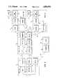
- FIG. 2is a system functional diagram further illustrating its operation
- FIG. 3illustrates the components of an individual control unit processor
- FIG. 4shows one preferred format for the coded control messages passed between the command unit and the individual control unit when the latter are in a "ready" state
- FIG. 4-Ashows a preferred format for the coded control messages passed from the command unit causing individual control units to arm and fire;
- FIG. 5depicts in partial section an explosive charge arrangement advantageously used in the invention
- FIG. 6shows the arrangement of a detonation switch in the deactivated position
- FIG. 6-Ashows the arrangment of the switch of FIG. 6 in an activated or "fire” position.
- FIG. 1there is shown a generalized, functional diagram of the system of this invention together with the major sub-systems and their interaction.
- the detonating system of this invention shown generally at 10includes three major sub-systems.
- One of the sub-systemsis a command unit 11 which includes a command console, radio transmitters and receivers and microprocessors.
- a second sub-systemcomprises a translator unit 12 which is designed to act as a relay point between the command unit land one or more individual control units 13.
- the functions of translator unit 12can be incorporated into the command unit 11 but that arrangement is much less preferred. Provision of a translator unit, as is illustrated, ensures a very strong signal for the individual control units 13 independent of multi-path reflections, transmitter fading and other radio propagation phenomena that may exist. It also allows transmitters in the individual control units 13, used to feedback status information to the command unit, to be low powered thus allowing reduced size and complexity.
- Each individual control unit 13contains a radio receiver which receives signals from the command unit 11 relayed through the translator 12. Individual control units also contain firing logic and firing mechanisms for detonating an explosive charge 14.
- Charge 14is connected to its control unit by means of signal transmitting means 15 which may be an electrical wire conductor or in certain embodiments, may be an optical fiber. Wire 15 is made sufficiently long, typically five to fifteen feet, so as to ensure that control units 13 survive the blast of charge 14 without damage.
- command unit 11is provided with antennas 16, for transmission of radio signal 17 for reception by antenna 18 of translator 12, and 19 for the reception of radio signal 20 broadcast by translator antenna 21.
- Translator 12is also arranged to broadcast signals 22, which may be a relay of signal 17, for reception by individual control units 13 through antennas 23.
- control units 13are arranged to broadcast a signal 24, representative of system status, by means of antennas 25.
- command unit 11is shown in dashed outline and includes a command console 31, a processor 32, a radio transmitter 33 and a radio receiver 34. Both transmitter 33 and receiver 34 are preferably FM.
- Console 31is arranged so as to allow an operator to determine the status of any or all of the individual control units and to command the arming, disarming or firing of any or all of the explosive charges 14 either simultaneiously or in any timed sequence. The system is designed such that a disarm command will override all else.
- an optional sub-system 40comprising a closed circuit television camera 41 and an associated transmitter 42.
- Camera 41may be used to monitor the locations of charges 14 and transmit that picture back to closed circuit television receiver 35 via signal 43.
- the picturemay be displayed on a video monitor incorporated in command console 31.
- Translator sub-system 12includes and FM radio receiver 51 which is adapted to pick up signal 17 produced by command unit transmitter 33.
- Subsystem 12also includes an AM radio receiver 53 to pick up signal 24 from individual control units 13. That singal is passed to encoding-decoding processor 54 which produces a data stream re-broadcast as signal 20 by FM transmitter 55.
- Each individual control unit 13is provided with a command receiver 61 which is adapted to receive either the command unit signal 17 or the re-broadcast signal 22 from translator 12. That radio signal is passed to a processor-decoder means 62 which is shown in greater detail in FIG. 3. Processor-decoder 62 functions to arm and activate firing mechanism 63, upon proper command, thus detonating explosive charge. Means 62 also performs housekeeping functions including reporting on the status of mechanism 63 and coding that status information for transmission back to translator 12 via radio signal 24 broadcast by transmitter 64.
- Module 62is designed to accept and respond to messages from the command unit 11, including those relayed through translator 12, to arm, disarm, or fire the explosive charge 14 associated with each individual control unit. All such messages between the command unit and the individual control units must be absolutely distinctive so that the chances of an individual control unit responding to some random signal, or to a signal directed to another individual control unit, is essentially zero. Consequently, each individual control unit is provided with an identifying code which, in a preferred embodiment, is a Mersenne prime number.
- FIGS. 4 and 4-Aprovide examples of preferred formats of the coded messages.
- a messageincludes a preamble and a designation code sequence as is diagrammed in FIG. 4.
- the preambleis processed by preamble decoder 71 and is used for synchronization of clock 72 with that of the command unit and to alert housekeeping module 73 to be ready to accept data.
- a designation code sequenceconsisting of a marker identifying the beginning of a message and the designation itself.
- the designationpreferably is a Mersenne prime number.
- the preamble and designation portions of the messageare 15-bit binary words corresponding to a Mersenne prime number. Redundancy is built into the system to further reduce the possibility of the control units responding to a spurious signal. That is accomplished by the transmission of at least two separate destination codes multiple times.
- a first designation decoder 74 and a second designation decoder 75are provided to process the separate message codes and each decoder must correctly receive its transmitted code four out of five times in order for module 62 to recognize a valid designation. Summarizing those requirements, an individual control unit is placed on an alert status only after it has received two separate specific messages, each 15 bits long, in four out of five transmissions.
- the twenty charges and their control unitsare numbered sequentially and that four of the charges, numbers 3, 11, 12 and 17, are designated for simultaneous detonation.
- the clock 72 of each of the twenty individual control unitsis synchronized with the clock of the command unit and each control unit then watches to see if its designations are being transmitted.
- the stream of digital data from the receiver 61 of each individual control unitis fed to module 62.
- Each of the twenty individual control unitshas a specific prime number for each decoder, or two prime numbers per unit, which it is set to recognize.
- the sets of prime numbers corresponding to each of control units 3, 11, 12 and 17are broadcast in the signal format illustrated in FIG. 4.
- both decoders 74 and 75recognize their respective prime numbers in at least four of five transmissions, then the individual control unit is placed on alert status where it can accept further instructions. At that point, a signal is sent to the housekeeping component 73 indicating that its individual control unit has been designated by the command unit. Component 73 then sends a message to transmitter 64, confirming the decision, for broadcast back to translator 12. That information is decoded, combined with similar information from the other individual control units, and is transmitted back to the command unit.
- That consolepreferably includes visual indication of the status of each individual control unit. In this case, the console would show by appropriate indicia that control units 3, 11, 12 and 17 were in an alert status while the remaining sixteen units were inactive.
- the new message formatincludes a 20-bit binary word which commands the individual control unit to arm its circuits. This new message is received and processed in the arming command decoder 76 which in turn transmits the command to the arm logic discriminator 77.
- Arm logic discriminator 77performs two functions. First, it monitors the status of the system to ensure that a disarm command has not been issued. The official in control of the command console always has the ability to transmit a disarm signal. That signal is received and processed in the disarm command decoder 78 and the command is then transmitted to the arm logic discriminator 77. Discriminator 77 is arranged so as to give a disarm signal a higher priority than an arm signal. A disarm command prevents discriminator 77 from passing the command through to the arming logic circuit 79.
- the second function of the arming logic discriminator 77is to keep track of how long it has been since the last arming command was received.
- the systemis designed so that it must receive a new arm command periodically else it reverts back to the alert status. Preferably, a new arm command must be received once every three frames of data for the system to remain armed. If the arming logic discriminator determines that the arming command is valid, that there has been no disarm command and that the arming command has occurred frequently enough, it then passes positive confirmation of arming to the arming logic circuit 79.
- the housekeeping component 73 of the processor 62monitors the arming logic circuit 79 and determines that the individual control unit is in the armed mode. It encodes this data and sends it back to the command unit where the command console 31 provides the responsible official with visual confirmation that the arm signal has been received by the designated individual control unit.
- the visual confirmationmay, for example, take the form of a status light provided for each individual control unit which will be illuminated whenever the unit is in an armed status.
- the only thing yet required to cause the designated individual control units to detonate their respective explosive chargesis to transmit a firing command. If prior to issuing a fire command the responsible official decides to disarm the designated units, he is provided a disarm the designated units to come out of the arm position and revert back to an alert status. Alternatively, the system allows for each or all of the individual control units to be de-designated by appropriate command thus providing redundancy in the disarming circuits.
- the explosive charges associated with their respective individual control units, in this example units 3, 11, 12 and 17,can now be detonated at will by the activation of a fire switch located at the command console 31. That will cause a fire command to be encoded on the data stream in a format such as is diagrammed in FIG. 4-A.
- the commandis transmitted to the individual control units where it is detected and decoded by the fire command decoder 80 of processor 62. If decoder 80 recognizes the fire command as authentic, it transmits a fire signal to firing logic module 81. If, at the time the fire signal is received by firing logic module 81, there is a positive output from the arming logic 79 and there is no disarm signal present the firing logic will issue a firing command.
- This fire commandis transmitted through electrical or optical conductors 15 to a mechanism for detonating the charge.
- the firing mechanism itselfis of conventional type and preferably comprise a capacitor discharge blasting machine. Such devices are well known and comprise a capacitor which stores a quantity of electricity. The capacitor is discharged into the firing circuit upon activation of a firing switch causing an electric blasting cap to detonate the explosive charge.
- the charge meanspreferably comprises a shaped charge including a solid explosive 101 placed in back of conical liner 102 so as to direct the force of the explosion fowardly along the axis 103 of liner 102.
- An electric blasting cap 104is provided at the rear of charge 101 to detonate the explosive.
- Cap 104is connected to initiating switch 105 through electrically conducting leg wires 106.
- Switch 105is operably connected to switch activator 107 through linkage means 08.
- Activator 107is caused to operate and change the position of switch 105 upon receiving a signal, which may be electrical or optical, from the individual control unit associated with the charge by way of conductors 15.
- a surge of electric currentis supplied to the switch from capacitor discharge blasting machine 110 or similar device through conductor pair 111 and 112.
- the entire charge 14is preferably contained within housing means 113 which functions to protect the charge from damage during transport and placement. It is preferred also that an electromagnetic shielding means 114 be provided to completely surround the charge. Shielding means 114 and housing means 113 may be combined together in a single element.
- FIG. 6shows the arrangement of initiating, or detonating, switch 105 in the deactivated position while FIG. 6-A diagrams the same switch in a "fire" position.
- conductor 111which is one of the two conductors connecting blasting machine 110 with switch 105, branches to go to ground 121 and to a switch terminal post 122. Another branch of conductor 111 forms one of the leg wires (designated 106 in FIG. 5) of blasting cap 104. The other conductor 112 from blasting machine 110 is directed to switch terminal post 123. The other leg wire 106 of blasting cap 104 branches to form a pair of opposed switch terminal posts 124 and 125.
- switch contact bar 126which is movable by switch activator means 107 (FIG. 5) between two positions. In the first position, the deactivated position shown in FIG. 6, contact bar 126 connects switch terminals 122 and 124. As may be appreciated from the diagram, this shorts out and grounds the two leg wires 106 of cap 104 preventing any current flow through the bridge wire of cap 104. In its second position, the "fire" position shown in FIG. 6-A, contact bar 126 connects terminals 123 and 125. This completes a circuit of conductor 111 through blasting cap 104 and returning through conductor 112 thus allowing blasting machine 110 to discharge causing the detonation of cap 104 and explosive 101.
- a shaped chargeis most useful for gaining entrance into an enclosure as, for example, detaching a door from its hinges and latches. In other circumstances a charge might be configured to maximize its blast effect to stun and confuse persons in proximity to the charge. Likewise, detonating switches different from that one illustrated in FIGS. 6 and 6-A may be used to advantage.
- the conductors 15 connecting each individual control unit 13 with its charge 14are kept as short as possible so as to minimize induced currents while at the same time allowing the control units to survive the blast without damage.
Landscapes
- Engineering & Computer Science (AREA)
- General Engineering & Computer Science (AREA)
- Selective Calling Equipment (AREA)
Abstract
Description
Claims (19)
Priority Applications (2)
| Application Number | Priority Date | Filing Date | Title |
|---|---|---|---|
| US06/927,362US4884506A (en) | 1986-11-06 | 1986-11-06 | Remote detonation of explosive charges |
| PCT/US1989/005074WO1991007637A1 (en) | 1986-11-06 | 1989-11-20 | Remote detonation of explosive charges |
Applications Claiming Priority (1)
| Application Number | Priority Date | Filing Date | Title |
|---|---|---|---|
| US06/927,362US4884506A (en) | 1986-11-06 | 1986-11-06 | Remote detonation of explosive charges |
Publications (1)
| Publication Number | Publication Date |
|---|---|
| US4884506Atrue US4884506A (en) | 1989-12-05 |
Family
ID=25454641
Family Applications (1)
| Application Number | Title | Priority Date | Filing Date |
|---|---|---|---|
| US06/927,362Expired - LifetimeUS4884506A (en) | 1986-11-06 | 1986-11-06 | Remote detonation of explosive charges |
Country Status (2)
| Country | Link |
|---|---|
| US (1) | US4884506A (en) |
| WO (1) | WO1991007637A1 (en) |
Cited By (103)
| Publication number | Priority date | Publication date | Assignee | Title |
|---|---|---|---|---|
| WO1991007637A1 (en)* | 1986-11-06 | 1991-05-30 | Electronic Warfare Associates, Inc. | Remote detonation of explosive charges |
| US5069129A (en)* | 1989-11-24 | 1991-12-03 | Shigeaki Kunitomo | Igniting apparatus for explosive substances |
| US5090321A (en)* | 1985-06-28 | 1992-02-25 | Ici Australia Ltd | Detonator actuator |
| GB2247513A (en)* | 1990-08-28 | 1992-03-04 | Rheinmetall Gmbh | Mine programming apparatus. |
| DE4031089A1 (en)* | 1990-10-02 | 1992-04-09 | Diehl Gmbh & Co | Mine system |
| FR2676561A1 (en)* | 1991-05-16 | 1992-11-20 | Alsetex | Conversational system for managing the activity of mines, activated by a server processor |
| US5415103A (en)* | 1994-08-17 | 1995-05-16 | Texas Instruments Incorporated | Programmable munitions device |
| US5458063A (en)* | 1993-02-01 | 1995-10-17 | Giat Industries | Demining device |
| US5539636A (en)* | 1992-12-07 | 1996-07-23 | Csir | Surface blasting system |
| US5767437A (en)* | 1997-03-20 | 1998-06-16 | Rogers; Donald L. | Digital remote pyrotactic firing mechanism |
| US5877696A (en)* | 1996-04-09 | 1999-03-02 | Powell; Roger A. | Security system for warheads |
| WO1999026038A1 (en)* | 1997-11-18 | 1999-05-27 | Aris Mardirossian, Inc. | Land mine arming/disarming system |
| US6079333A (en)* | 1998-06-12 | 2000-06-27 | Trimble Navigation Limited | GPS controlled blaster |
| WO2001022180A1 (en)* | 1999-09-17 | 2001-03-29 | Pyrologic Ltd. | Fireworks remote control system |
| US6247408B1 (en)* | 1999-11-08 | 2001-06-19 | The United States Of America As Represented By The Secretary Of The Army | System for sympathetic detonation of explosives |
| US6260483B1 (en)* | 1998-04-24 | 2001-07-17 | Richard N. Snyder | Remote radio controlled plasma firing system |
| WO2001059401A1 (en)* | 2000-02-11 | 2001-08-16 | Inco Limited | Remote wireless detonator system |
| US6283227B1 (en)* | 1998-10-27 | 2001-09-04 | Schlumberger Technology Corporation | Downhole activation system that assigns and retrieves identifiers |
| US6422145B1 (en) | 1997-11-06 | 2002-07-23 | Rocktek Ltd. | Controlled electromagnetic induction detonation system for initiation of a detonatable material |
| US6460460B1 (en)* | 2000-06-29 | 2002-10-08 | University Of Maryland | Laser-activated grenade with agile target effects |
| US6490977B1 (en) | 1998-03-30 | 2002-12-10 | Magicfire, Inc. | Precision pyrotechnic display system and method having increased safety and timing accuracy |
| US6546873B1 (en)* | 2000-04-03 | 2003-04-15 | The United States Of America As Represented By The Secretary Of The Army | Apparatus for remote activation of equipment and demolition charges |
| DE20217020U1 (en) | 2002-11-01 | 2003-04-24 | Giehle, Andreas, 14476 Leest | FAG 1-433 / radio remote ignition |
| WO2003076868A1 (en) | 2002-03-11 | 2003-09-18 | Dyno Nobel Sweden Ab | Detonator system and method in connection with the same |
| US6637339B1 (en)* | 1999-03-20 | 2003-10-28 | Dynamit Nobel Gmbh Explosivstoff Und Systemtechnik | Method for exchanging data between a device for programming and triggering electronic detonators and said detonators |
| US6679175B2 (en) | 2001-07-19 | 2004-01-20 | Rocktek Limited | Cartridge and method for small charge breaking |
| US6708619B2 (en) | 2000-02-29 | 2004-03-23 | Rocktek Limited | Cartridge shell and cartridge for blast holes and method of use |
| US20040112238A1 (en)* | 2002-12-13 | 2004-06-17 | Sandia National Laboratories | System for controlling activation of remotely located device |
| US20040134658A1 (en)* | 2003-01-09 | 2004-07-15 | Bell Matthew Robert George | Casing conveyed well perforating apparatus and method |
| US6799517B1 (en)* | 2000-03-14 | 2004-10-05 | Brtrc Technology Research Corporation | Mixed mine alternative system |
| WO2005005914A1 (en)* | 2003-07-15 | 2005-01-20 | Special Devices, Incorporated | Detonator utilizing selection of logger mode or blaster mode based on sensed voltages |
| US6860206B1 (en)* | 2001-12-14 | 2005-03-01 | Irobot Corporation | Remote digital firing system |
| US20050045331A1 (en)* | 1998-10-27 | 2005-03-03 | Lerche Nolan C. | Secure activation of a downhole device |
| US20050103219A1 (en)* | 2003-11-04 | 2005-05-19 | Advanced Initiation Systems, Inc. | Positional blasting system |
| WO2006010172A1 (en)* | 2004-07-21 | 2006-01-26 | Detnet International Limited | Blasting system and method of controlling a blasting operation |
| US20060086277A1 (en)* | 1998-03-30 | 2006-04-27 | George Bossarte | Precision pyrotechnic display system and method having increased safety and timing accuracy |
| WO2006076778A1 (en)* | 2005-01-24 | 2006-07-27 | Orica Explosives Technology Pty Ltd | Data communication in electronic blasting systems |
| US20060178085A1 (en)* | 2005-02-04 | 2006-08-10 | Nicholas Sotereanos | Remotely controlled vehicle |
| US20060237955A1 (en)* | 2003-06-04 | 2006-10-26 | Continental Teves Ag & Co. Ohg | Method and device for deactivating a pyrotechnic actuator in a motor vehicle |
| US7130624B1 (en) | 2003-11-12 | 2006-10-31 | Jackson Richard H | System and method for destabilizing improvised explosive devices |
| US20070119326A1 (en)* | 2001-12-14 | 2007-05-31 | Rudakevych Pavlo E | Remote digital firing system |
| US20070214950A1 (en)* | 2006-03-20 | 2007-09-20 | Technology Patents, Llc | Anti-terrorist system |
| WO2007124539A1 (en)* | 2006-04-28 | 2007-11-08 | Orica Explosives Technology Pty Ltd | Wireless electronic booster, and methods of blasting |
| WO2008035987A1 (en)* | 2006-09-19 | 2008-03-27 | Mas Zengrange (Nz) Ltd | Remote initiator for the remote initiation of explosive charges |
| US20080083344A1 (en)* | 2005-11-14 | 2008-04-10 | Deguire Daniel R | Safe and arm system for a robot |
| US20080174448A1 (en)* | 2006-10-31 | 2008-07-24 | Edison Hudson | Modular Controller |
| US20080245251A1 (en)* | 2005-05-09 | 2008-10-09 | Riaan Lingerfelder Van Wyk | Power Management Of Blasting Lead-In System |
| US20080277909A1 (en)* | 2005-03-15 | 2008-11-13 | Kazuaki Matsuda | Actuator of Passenger Protection Device |
| US20080307993A1 (en)* | 2004-11-02 | 2008-12-18 | Orica Explosives Technology Pty Ltd | Wireless Detonator Assemblies, Corresponding Blasting Apparatuses, and Methods of Blasting |
| US20090025371A1 (en)* | 2007-06-19 | 2009-01-29 | Jonas Hermansson | Control of an Exhaust Gas Aftertreatment Device in a Hybrid Vehicle |
| US7546891B2 (en) | 1998-03-27 | 2009-06-16 | Irobot Corporation | Robotic platform |
| US20090198505A1 (en)* | 2008-02-05 | 2009-08-06 | Peter Gipps | Interactive path planning with dynamic costing |
| US20100085210A1 (en)* | 2008-10-02 | 2010-04-08 | Bonavides Clovis S | Actuating Downhole Devices in a Wellbore |
| US20100309029A1 (en)* | 2009-06-05 | 2010-12-09 | Apple Inc. | Efficiently embedding information onto a keyboard membrane |
| US20110087740A1 (en)* | 2009-10-12 | 2011-04-14 | International Business Machines Corporation | Leveraging point-in-time knowledge to respond to e-mail |
| US8079307B2 (en) | 2005-10-05 | 2011-12-20 | Mckinley Paul | Electric match assembly with isolated lift and burst function for a pyrotechnic device |
| WO2012061850A1 (en)* | 2010-11-04 | 2012-05-10 | Detnet South Africa (Pty) Ltd | Wireless blasting module |
| US20120192744A1 (en)* | 2009-09-16 | 2012-08-02 | Mas Zengrange (Nz) Limited | Remote initiator breaching system |
| US8374721B2 (en) | 2005-12-02 | 2013-02-12 | Irobot Corporation | Robot system |
| US8375838B2 (en) | 2001-12-14 | 2013-02-19 | Irobot Corporation | Remote digital firing system |
| US20130098257A1 (en)* | 2010-05-07 | 2013-04-25 | Orica International Pte Ltd | Method of blasting |
| WO2013106850A1 (en)* | 2012-01-13 | 2013-07-18 | Los Alamos National Security, Llc | Detonation command and control |
| US8584307B2 (en) | 2005-12-02 | 2013-11-19 | Irobot Corporation | Modular robot |
| JP2013238368A (en)* | 2012-05-16 | 2013-11-28 | Nishimatsu Constr Co Ltd | Blasting method and blasting system |
| US8600553B2 (en) | 2005-12-02 | 2013-12-03 | Irobot Corporation | Coverage robot mobility |
| US8606401B2 (en) | 2005-12-02 | 2013-12-10 | Irobot Corporation | Autonomous coverage robot navigation system |
| EP2169343A3 (en)* | 2008-09-30 | 2014-01-22 | General Electric Company | Store management system and method of operating the same |
| ES2557059A1 (en)* | 2014-07-21 | 2016-01-21 | Ignacio GÓMEZ MAQUEDA | METHOD AND SYSTEM FOR REMOTE ACTIVATION CONTROL |
| WO2016086242A3 (en)* | 2014-11-28 | 2016-08-11 | Detnet South Africa (Pty) Ltd | Electronic detonator initiation |
| US9464508B2 (en) | 1998-10-27 | 2016-10-11 | Schlumberger Technology Corporation | Interactive and/or secure activation of a tool |
| US9568294B2 (en) | 2013-03-08 | 2017-02-14 | Ensign-Bickford Aerospace & Defense Company | Signal encrypted digital detonator system |
| US20170089680A1 (en)* | 2013-12-02 | 2017-03-30 | Austin Star Detonator Company | Method and apparatus for wireless blasting |
| CN106610253B (en)* | 2016-12-08 | 2017-12-22 | 娄文忠 | A kind of electric detonator detonation system and its control method by repeater communication |
| US9861917B2 (en) | 2010-06-11 | 2018-01-09 | Wix Filtration Corp. Llc | Spin-on filter assembly |
| US20180328702A1 (en)* | 2015-11-09 | 2018-11-15 | Detnet South Africa (Pty) Ltd | Wireless detonator |
| US10246982B2 (en) | 2013-07-15 | 2019-04-02 | Triad National Security, Llc | Casings for use in a system for fracturing rock within a bore |
| US10273788B2 (en) | 2014-05-23 | 2019-04-30 | Hunting Titan, Inc. | Box by pin perforating gun system and methods |
| US10273792B2 (en) | 2013-07-15 | 2019-04-30 | Triad National Security, Llc | Multi-stage geologic fracturing |
| US10294767B2 (en) | 2013-07-15 | 2019-05-21 | Triad National Security, Llc | Fluid transport systems for use in a downhole explosive fracturing system |
| US10443360B2 (en)* | 2016-09-27 | 2019-10-15 | Schlumberger Technology Corporation | Non-detonable shaped charge and activation |
| US10480919B1 (en)* | 2017-03-10 | 2019-11-19 | Leonardo S.P.A. | Addition of a telemetry function in an artillery radar device fuze |
| US10634475B2 (en)* | 2016-07-04 | 2020-04-28 | Davey Bickford | Fire control unit for a set of detonators and firing system |
| US10844696B2 (en) | 2018-07-17 | 2020-11-24 | DynaEnergetics Europe GmbH | Positioning device for shaped charges in a perforating gun module |
| US10856631B1 (en)* | 2020-03-30 | 2020-12-08 | Joerg Schulhofer | Device, system, and method for wirelessly controlling an array of beach umbrellas |
| US10900333B2 (en) | 2015-11-12 | 2021-01-26 | Hunting Titan, Inc. | Contact plunger cartridge assembly |
| US11078764B2 (en) | 2014-05-05 | 2021-08-03 | DynaEnergetics Europe GmbH | Initiator head assembly |
| US11299967B2 (en) | 2014-05-23 | 2022-04-12 | Hunting Titan, Inc. | Box by pin perforating gun system and methods |
| US11480038B2 (en) | 2019-12-17 | 2022-10-25 | DynaEnergetics Europe GmbH | Modular perforating gun system |
| US11591885B2 (en) | 2018-05-31 | 2023-02-28 | DynaEnergetics Europe GmbH | Selective untethered drone string for downhole oil and gas wellbore operations |
| US11808098B2 (en) | 2018-08-20 | 2023-11-07 | DynaEnergetics Europe GmbH | System and method to deploy and control autonomous devices |
| US11808093B2 (en) | 2018-07-17 | 2023-11-07 | DynaEnergetics Europe GmbH | Oriented perforating system |
| USD1010758S1 (en) | 2019-02-11 | 2024-01-09 | DynaEnergetics Europe GmbH | Gun body |
| US11905823B2 (en) | 2018-05-31 | 2024-02-20 | DynaEnergetics Europe GmbH | Systems and methods for marker inclusion in a wellbore |
| USD1019709S1 (en) | 2019-02-11 | 2024-03-26 | DynaEnergetics Europe GmbH | Charge holder |
| US11946728B2 (en) | 2019-12-10 | 2024-04-02 | DynaEnergetics Europe GmbH | Initiator head with circuit board |
| USD1034879S1 (en) | 2019-02-11 | 2024-07-09 | DynaEnergetics Europe GmbH | Gun body |
| US12031417B2 (en) | 2018-05-31 | 2024-07-09 | DynaEnergetics Europe GmbH | Untethered drone string for downhole oil and gas wellbore operations |
| USRE50204E1 (en) | 2013-08-26 | 2024-11-12 | DynaEnergetics Europe GmbH | Perforating gun and detonator assembly |
| RU230347U1 (en)* | 2024-05-28 | 2024-11-28 | Российская Федерация, от имени которой выступает Министерство обороны Российской Федерации | Executive radio device for remote activation of the igniter of charges |
| US12215576B2 (en) | 2013-07-18 | 2025-02-04 | DynaEnergetics Europe GmbH | Single charge perforation gun and system |
| US12313391B2 (en) | 2015-09-16 | 2025-05-27 | Orica International Pte Ltd | Wireless initiation device |
| US12338718B2 (en) | 2021-03-03 | 2025-06-24 | DynaEnergetics Europe GmbH | Orienting perforation gun assembly |
| US12352553B1 (en)* | 2023-05-30 | 2025-07-08 | The United States Of America As Represented By The Secretary Of The Navy | Remote firing system |
Families Citing this family (4)
| Publication number | Priority date | Publication date | Assignee | Title |
|---|---|---|---|---|
| FR2688583B1 (en)* | 1992-03-10 | 1995-07-07 | Spada Entr Jean | METHOD AND APPARATUS FOR FIREFIGHTING ACCORDING TO A DETERMINED SEQUENCE OF A PLURALITY OF EXPLOSIVE CHARGES. |
| FR2727756B1 (en)* | 1994-12-06 | 1998-07-10 | Thomson Dasa Armement | LOCATION OF MINES FOR MINING |
| GB9501306D0 (en)* | 1995-01-24 | 1995-03-15 | Explosive Dev Ltd | Improvements in or relating to explosive firing arrangements |
| BRPI0213031B1 (en)* | 2001-10-02 | 2016-04-12 | Orica Explosives Tech Pty Ltd | detonation system, method of operating a detonation system and initiator for a detonator |
Citations (7)
| Publication number | Priority date | Publication date | Assignee | Title |
|---|---|---|---|---|
| US2411787A (en)* | 1942-09-26 | 1946-11-26 | Rca Corp | Radio controlled mine |
| US2918001A (en)* | 1957-09-30 | 1959-12-22 | William W Garber | Radio-proof electric firing device |
| US3370140A (en)* | 1966-11-16 | 1968-02-20 | Robert E. Betts | Electro-magnetic radiation proof plug and receptacle |
| US3750586A (en)* | 1971-06-25 | 1973-08-07 | Us Navy | Firing device |
| US4145970A (en)* | 1976-03-30 | 1979-03-27 | Tri Electronics Ab | Electric detonator cap |
| US4527480A (en)* | 1978-10-02 | 1985-07-09 | The United States Of America As Represented By The Secretary Of Transportation | Means for the deactivation of electric blasting caps |
| US4576093A (en)* | 1984-04-12 | 1986-03-18 | Snyder Richard N | Remote radio blasting |
Family Cites Families (4)
| Publication number | Priority date | Publication date | Assignee | Title |
|---|---|---|---|---|
| CA1233896A (en)* | 1983-04-11 | 1988-03-08 | Kenneth N. Jarrott | Programmable electronic delay fuse |
| US4674047A (en)* | 1984-01-31 | 1987-06-16 | The Curators Of The University Of Missouri | Integrated detonator delay circuits and firing console |
| WO1987000265A1 (en)* | 1985-06-28 | 1987-01-15 | Moorhouse, D., J. | Detonator actuator |
| US4884506A (en)* | 1986-11-06 | 1989-12-05 | Electronic Warfare Associates, Inc. | Remote detonation of explosive charges |
- 1986
- 1986-11-06USUS06/927,362patent/US4884506A/ennot_activeExpired - Lifetime
- 1989
- 1989-11-20WOPCT/US1989/005074patent/WO1991007637A1/enunknown
Patent Citations (7)
| Publication number | Priority date | Publication date | Assignee | Title |
|---|---|---|---|---|
| US2411787A (en)* | 1942-09-26 | 1946-11-26 | Rca Corp | Radio controlled mine |
| US2918001A (en)* | 1957-09-30 | 1959-12-22 | William W Garber | Radio-proof electric firing device |
| US3370140A (en)* | 1966-11-16 | 1968-02-20 | Robert E. Betts | Electro-magnetic radiation proof plug and receptacle |
| US3750586A (en)* | 1971-06-25 | 1973-08-07 | Us Navy | Firing device |
| US4145970A (en)* | 1976-03-30 | 1979-03-27 | Tri Electronics Ab | Electric detonator cap |
| US4527480A (en)* | 1978-10-02 | 1985-07-09 | The United States Of America As Represented By The Secretary Of Transportation | Means for the deactivation of electric blasting caps |
| US4576093A (en)* | 1984-04-12 | 1986-03-18 | Snyder Richard N | Remote radio blasting |
Non-Patent Citations (2)
| Title |
|---|
| Blasters Handbook, E. I. du Pont de Nemours & Co. (Inc.), 1977, pp. 87 91, 138 149, 152 159, 174 193 and 396 403.* |
| Blasters Handbook, E. I. du Pont de Nemours & Co. (Inc.), 1977, pp. 87-91, 138-149, 152-159, 174-193 and 396-403. |
Cited By (201)
| Publication number | Priority date | Publication date | Assignee | Title |
|---|---|---|---|---|
| US5090321A (en)* | 1985-06-28 | 1992-02-25 | Ici Australia Ltd | Detonator actuator |
| WO1991007637A1 (en)* | 1986-11-06 | 1991-05-30 | Electronic Warfare Associates, Inc. | Remote detonation of explosive charges |
| US5069129A (en)* | 1989-11-24 | 1991-12-03 | Shigeaki Kunitomo | Igniting apparatus for explosive substances |
| GB2247513A (en)* | 1990-08-28 | 1992-03-04 | Rheinmetall Gmbh | Mine programming apparatus. |
| US5136949A (en)* | 1990-08-28 | 1992-08-11 | Rheinmetall Gmbh | Mine system |
| GB2247513B (en)* | 1990-08-28 | 1994-04-27 | Rheinmetall Gmbh | Mine programming apparatus |
| DE4031089A1 (en)* | 1990-10-02 | 1992-04-09 | Diehl Gmbh & Co | Mine system |
| FR2676561A1 (en)* | 1991-05-16 | 1992-11-20 | Alsetex | Conversational system for managing the activity of mines, activated by a server processor |
| US5539636A (en)* | 1992-12-07 | 1996-07-23 | Csir | Surface blasting system |
| US5458063A (en)* | 1993-02-01 | 1995-10-17 | Giat Industries | Demining device |
| US5415103A (en)* | 1994-08-17 | 1995-05-16 | Texas Instruments Incorporated | Programmable munitions device |
| US5877696A (en)* | 1996-04-09 | 1999-03-02 | Powell; Roger A. | Security system for warheads |
| US5767437A (en)* | 1997-03-20 | 1998-06-16 | Rogers; Donald L. | Digital remote pyrotactic firing mechanism |
| US6422145B1 (en) | 1997-11-06 | 2002-07-23 | Rocktek Ltd. | Controlled electromagnetic induction detonation system for initiation of a detonatable material |
| WO1999026038A1 (en)* | 1997-11-18 | 1999-05-27 | Aris Mardirossian, Inc. | Land mine arming/disarming system |
| US6014932A (en)* | 1997-11-18 | 2000-01-18 | Technology Patents, Llc | Land mine arming/disarming system |
| US8763732B2 (en) | 1998-03-27 | 2014-07-01 | Irobot Corporation | Robotic platform |
| US8113304B2 (en) | 1998-03-27 | 2012-02-14 | Irobot Corporation | Robotic platform |
| US8365848B2 (en) | 1998-03-27 | 2013-02-05 | Irobot Corporation | Robotic platform |
| US7597162B2 (en) | 1998-03-27 | 2009-10-06 | Irobot Corporation | Robotic platform |
| US7556108B2 (en) | 1998-03-27 | 2009-07-07 | Irobot Corporation | Robotic platform |
| US9248874B2 (en) | 1998-03-27 | 2016-02-02 | Irobot Corporation | Robotic platform |
| US7546891B2 (en) | 1998-03-27 | 2009-06-16 | Irobot Corporation | Robotic platform |
| US9573638B2 (en) | 1998-03-27 | 2017-02-21 | Irobot Defense Holdings, Inc. | Robotic platform |
| US6490977B1 (en) | 1998-03-30 | 2002-12-10 | Magicfire, Inc. | Precision pyrotechnic display system and method having increased safety and timing accuracy |
| US8516963B2 (en) | 1998-03-30 | 2013-08-27 | Magicfire, Inc. | Precision pyrotechnic display system and method having increased safety and timing accuracy |
| US7617777B2 (en) | 1998-03-30 | 2009-11-17 | Magicfire, Inc. | Precision pyrotechnic display system and method having increased safety and timing accuracy |
| US6857369B2 (en) | 1998-03-30 | 2005-02-22 | Magic Fire, Inc. | Precision pyrotechnic display system and method having increased safety and timing accuracy |
| US20070295237A1 (en)* | 1998-03-30 | 2007-12-27 | George Bossarte | Precision pyrotechnic display system and method having increased safety and timing accuracy |
| US9400159B2 (en) | 1998-03-30 | 2016-07-26 | Magicfire, Inc. | Precision pyrotechnic display system and method having increased safety and timing accuracy |
| US7194959B2 (en) | 1998-03-30 | 2007-03-27 | Magicfire, Inc. | Precision pyrotechnic display system and method having increased safety and timing accuracy |
| US20060086277A1 (en)* | 1998-03-30 | 2006-04-27 | George Bossarte | Precision pyrotechnic display system and method having increased safety and timing accuracy |
| US20060027119A1 (en)* | 1998-03-30 | 2006-02-09 | George Bossarte | Precision pyrotechnic display system and method having increased safety and timing accuracy |
| US6260483B1 (en)* | 1998-04-24 | 2001-07-17 | Richard N. Snyder | Remote radio controlled plasma firing system |
| US6079333A (en)* | 1998-06-12 | 2000-06-27 | Trimble Navigation Limited | GPS controlled blaster |
| US7347278B2 (en) | 1998-10-27 | 2008-03-25 | Schlumberger Technology Corporation | Secure activation of a downhole device |
| US9464508B2 (en) | 1998-10-27 | 2016-10-11 | Schlumberger Technology Corporation | Interactive and/or secure activation of a tool |
| US6604584B2 (en) | 1998-10-27 | 2003-08-12 | Schlumberger Technology Corporation | Downhole activation system |
| US20050045331A1 (en)* | 1998-10-27 | 2005-03-03 | Lerche Nolan C. | Secure activation of a downhole device |
| US6283227B1 (en)* | 1998-10-27 | 2001-09-04 | Schlumberger Technology Corporation | Downhole activation system that assigns and retrieves identifiers |
| US6637339B1 (en)* | 1999-03-20 | 2003-10-28 | Dynamit Nobel Gmbh Explosivstoff Und Systemtechnik | Method for exchanging data between a device for programming and triggering electronic detonators and said detonators |
| WO2001022180A1 (en)* | 1999-09-17 | 2001-03-29 | Pyrologic Ltd. | Fireworks remote control system |
| US6247408B1 (en)* | 1999-11-08 | 2001-06-19 | The United States Of America As Represented By The Secretary Of The Army | System for sympathetic detonation of explosives |
| WO2001059401A1 (en)* | 2000-02-11 | 2001-08-16 | Inco Limited | Remote wireless detonator system |
| US6708619B2 (en) | 2000-02-29 | 2004-03-23 | Rocktek Limited | Cartridge shell and cartridge for blast holes and method of use |
| US6799517B1 (en)* | 2000-03-14 | 2004-10-05 | Brtrc Technology Research Corporation | Mixed mine alternative system |
| US7137340B1 (en)* | 2000-03-14 | 2006-11-21 | Brtrc Technology Research Corporation | Mixed mine alternative system |
| US6546873B1 (en)* | 2000-04-03 | 2003-04-15 | The United States Of America As Represented By The Secretary Of The Army | Apparatus for remote activation of equipment and demolition charges |
| US6460460B1 (en)* | 2000-06-29 | 2002-10-08 | University Of Maryland | Laser-activated grenade with agile target effects |
| US6679175B2 (en) | 2001-07-19 | 2004-01-20 | Rocktek Limited | Cartridge and method for small charge breaking |
| US7143696B2 (en) | 2001-12-14 | 2006-12-05 | Irobot Corporation | Remote digital firing system |
| US20070119326A1 (en)* | 2001-12-14 | 2007-05-31 | Rudakevych Pavlo E | Remote digital firing system |
| US8375838B2 (en) | 2001-12-14 | 2013-02-19 | Irobot Corporation | Remote digital firing system |
| US20060037508A1 (en)* | 2001-12-14 | 2006-02-23 | Rudakevych Pavlo E | Remote digital firing system |
| US6860206B1 (en)* | 2001-12-14 | 2005-03-01 | Irobot Corporation | Remote digital firing system |
| US8109191B1 (en) | 2001-12-14 | 2012-02-07 | Irobot Corporation | Remote digital firing system |
| US7559269B2 (en) | 2001-12-14 | 2009-07-14 | Irobot Corporation | Remote digital firing system |
| EP1488190B1 (en)* | 2002-03-11 | 2014-05-14 | Detnet South Africa (Pty) Ltd | Detonator system and method in connection with the same |
| US20050243499A1 (en)* | 2002-03-11 | 2005-11-03 | Sune Hallin | Detonator system and method in connection with the same |
| AU2003215985B2 (en)* | 2002-03-11 | 2009-04-23 | Detnet South Africa (Pty) Ltd | Detonator system and method in connection with the same |
| WO2003076868A1 (en) | 2002-03-11 | 2003-09-18 | Dyno Nobel Sweden Ab | Detonator system and method in connection with the same |
| US7370583B2 (en)* | 2002-03-11 | 2008-05-13 | Dyno Nobel Sweden Ab | Detonator system and method in connection with the same |
| DE20217020U1 (en) | 2002-11-01 | 2003-04-24 | Giehle, Andreas, 14476 Leest | FAG 1-433 / radio remote ignition |
| US20040112238A1 (en)* | 2002-12-13 | 2004-06-17 | Sandia National Laboratories | System for controlling activation of remotely located device |
| US7284489B2 (en) | 2003-01-09 | 2007-10-23 | Shell Oil Company | Casing conveyed well perforating apparatus and method |
| US20050121195A1 (en)* | 2003-01-09 | 2005-06-09 | Bell Matthew R.G. | Casing conveyed well perforating apparatus and method |
| US7975592B2 (en) | 2003-01-09 | 2011-07-12 | Shell Oil Company | Perforating apparatus, firing assembly, and method |
| US7284601B2 (en) | 2003-01-09 | 2007-10-23 | Shell Oil Company | Casing conveyed well perforating apparatus and method |
| US7350448B2 (en) | 2003-01-09 | 2008-04-01 | Shell Oil Company | Perforating apparatus, firing assembly, and method |
| US20050056426A1 (en)* | 2003-01-09 | 2005-03-17 | Bell Matthew Robert George | Casing conveyed well perforating apparatus and method |
| US6962202B2 (en) | 2003-01-09 | 2005-11-08 | Shell Oil Company | Casing conveyed well perforating apparatus and method |
| US20060000613A1 (en)* | 2003-01-09 | 2006-01-05 | Bell Matthew R G | Casing conveyed well perforating apparatus and method |
| US20040134658A1 (en)* | 2003-01-09 | 2004-07-15 | Bell Matthew Robert George | Casing conveyed well perforating apparatus and method |
| US20040206503A1 (en)* | 2003-01-09 | 2004-10-21 | Shell Oil Company | Casing conveyed well perforating apparatus and method |
| US20060060355A1 (en)* | 2003-01-09 | 2006-03-23 | Bell Matthew R G | Perforating apparatus, firing assembly, and method |
| US7461580B2 (en) | 2003-01-09 | 2008-12-09 | Shell Oil Company | Casing conveyed well perforating apparatus and method |
| US20060237955A1 (en)* | 2003-06-04 | 2006-10-26 | Continental Teves Ag & Co. Ohg | Method and device for deactivating a pyrotechnic actuator in a motor vehicle |
| WO2005005914A1 (en)* | 2003-07-15 | 2005-01-20 | Special Devices, Incorporated | Detonator utilizing selection of logger mode or blaster mode based on sensed voltages |
| US20050217525A1 (en)* | 2003-11-04 | 2005-10-06 | Advanced Initiation Systems, Inc. | Positional blasting system |
| US6941870B2 (en) | 2003-11-04 | 2005-09-13 | Advanced Initiation Systems, Inc. | Positional blasting system |
| US20050103219A1 (en)* | 2003-11-04 | 2005-05-19 | Advanced Initiation Systems, Inc. | Positional blasting system |
| US7650841B2 (en) | 2003-11-04 | 2010-01-26 | Davey Bickford Usa, Inc. | Positional blasting system |
| US7130624B1 (en) | 2003-11-12 | 2006-10-31 | Jackson Richard H | System and method for destabilizing improvised explosive devices |
| WO2006010172A1 (en)* | 2004-07-21 | 2006-01-26 | Detnet International Limited | Blasting system and method of controlling a blasting operation |
| US20080307993A1 (en)* | 2004-11-02 | 2008-12-18 | Orica Explosives Technology Pty Ltd | Wireless Detonator Assemblies, Corresponding Blasting Apparatuses, and Methods of Blasting |
| US7810430B2 (en) | 2004-11-02 | 2010-10-12 | Orica Explosives Technology Pty Ltd | Wireless detonator assemblies, corresponding blasting apparatuses, and methods of blasting |
| WO2006076778A1 (en)* | 2005-01-24 | 2006-07-27 | Orica Explosives Technology Pty Ltd | Data communication in electronic blasting systems |
| US20080041261A1 (en)* | 2005-01-24 | 2008-02-21 | Orica Explosives Technology Pty Ltd. | Data Communication in Electronic Blasting Systems |
| AU2006207831B2 (en)* | 2005-01-24 | 2011-09-15 | Orica Australia Pty Ltd | Data communication in electronic blasting systems |
| US7791858B2 (en) | 2005-01-24 | 2010-09-07 | Orica Explosives Technology Pty, Ltd. | Data communication in electronic blasting systems |
| US8083569B2 (en)* | 2005-02-04 | 2011-12-27 | Nicholas Sotereanos | Remotely controlled vehicle |
| US20060178085A1 (en)* | 2005-02-04 | 2006-08-10 | Nicholas Sotereanos | Remotely controlled vehicle |
| US20080277909A1 (en)* | 2005-03-15 | 2008-11-13 | Kazuaki Matsuda | Actuator of Passenger Protection Device |
| US20090293751A1 (en)* | 2005-05-09 | 2009-12-03 | Riaan Lingerfelder Van Wyk | Power management of blasting lead-in system |
| US20080245251A1 (en)* | 2005-05-09 | 2008-10-09 | Riaan Lingerfelder Van Wyk | Power Management Of Blasting Lead-In System |
| AU2006243909B2 (en)* | 2005-05-09 | 2011-03-10 | Detnet South Africa (Pty) Ltd | Power management of blasting lead-in system |
| US8820243B2 (en) | 2005-10-05 | 2014-09-02 | Magicfire, Inc. | Integrated electric match initiator module with isolated lift and burst function for a pyrotechnic device |
| US8079307B2 (en) | 2005-10-05 | 2011-12-20 | Mckinley Paul | Electric match assembly with isolated lift and burst function for a pyrotechnic device |
| US7905177B2 (en)* | 2005-11-14 | 2011-03-15 | Foster-Miller, Inc. | Safe and arm system for a robot |
| US20080083344A1 (en)* | 2005-11-14 | 2008-04-10 | Deguire Daniel R | Safe and arm system for a robot |
| US8584305B2 (en) | 2005-12-02 | 2013-11-19 | Irobot Corporation | Modular robot |
| US8584307B2 (en) | 2005-12-02 | 2013-11-19 | Irobot Corporation | Modular robot |
| US8606401B2 (en) | 2005-12-02 | 2013-12-10 | Irobot Corporation | Autonomous coverage robot navigation system |
| US8600553B2 (en) | 2005-12-02 | 2013-12-03 | Irobot Corporation | Coverage robot mobility |
| US8374721B2 (en) | 2005-12-02 | 2013-02-12 | Irobot Corporation | Robot system |
| US8950038B2 (en) | 2005-12-02 | 2015-02-10 | Irobot Corporation | Modular robot |
| US20070214950A1 (en)* | 2006-03-20 | 2007-09-20 | Technology Patents, Llc | Anti-terrorist system |
| US8250961B2 (en) | 2006-03-20 | 2012-08-28 | Technology Patents, Llc | Anti-terrorist system |
| US7784389B2 (en)* | 2006-03-20 | 2010-08-31 | Technology Patents, Llc | Anti-terrorist system |
| WO2007124539A1 (en)* | 2006-04-28 | 2007-11-08 | Orica Explosives Technology Pty Ltd | Wireless electronic booster, and methods of blasting |
| US20080156217A1 (en)* | 2006-04-28 | 2008-07-03 | Stewart Ronald F | Wireless electronic booster, and methods of blasting |
| US7778006B2 (en) | 2006-04-28 | 2010-08-17 | Orica Explosives Technology Pty Ltd. | Wireless electronic booster, and methods of blasting |
| US20100170411A1 (en)* | 2006-09-19 | 2010-07-08 | Mas Zengrange (Nz) Ltd | Remote initiator for the remote initiation of explosive charges |
| WO2008035987A1 (en)* | 2006-09-19 | 2008-03-27 | Mas Zengrange (Nz) Ltd | Remote initiator for the remote initiation of explosive charges |
| US8134822B2 (en) | 2006-09-19 | 2012-03-13 | Mas Zengrange (Nz) Ltd | Remote initiator for the remote initiation of explosive charges |
| US20080174448A1 (en)* | 2006-10-31 | 2008-07-24 | Edison Hudson | Modular Controller |
| US20090025371A1 (en)* | 2007-06-19 | 2009-01-29 | Jonas Hermansson | Control of an Exhaust Gas Aftertreatment Device in a Hybrid Vehicle |
| US20090198505A1 (en)* | 2008-02-05 | 2009-08-06 | Peter Gipps | Interactive path planning with dynamic costing |
| EP2169343A3 (en)* | 2008-09-30 | 2014-01-22 | General Electric Company | Store management system and method of operating the same |
| US8451137B2 (en)* | 2008-10-02 | 2013-05-28 | Halliburton Energy Services, Inc. | Actuating downhole devices in a wellbore |
| US20100085210A1 (en)* | 2008-10-02 | 2010-04-08 | Bonavides Clovis S | Actuating Downhole Devices in a Wellbore |
| US8441370B2 (en) | 2008-10-02 | 2013-05-14 | Halliburton Energy Services, Inc. | Actuating downhole devices in a wellbore |
| US20100309029A1 (en)* | 2009-06-05 | 2010-12-09 | Apple Inc. | Efficiently embedding information onto a keyboard membrane |
| EP2478325A4 (en)* | 2009-09-16 | 2014-03-19 | Mas Zengrange Nz Ltd | REMOTE PRIME-DETONATOR BLASTING SYSTEM |
| US8621998B2 (en)* | 2009-09-16 | 2014-01-07 | Mas Zengrange (Nz) Limited | Remote initiator breaching system |
| US20120192744A1 (en)* | 2009-09-16 | 2012-08-02 | Mas Zengrange (Nz) Limited | Remote initiator breaching system |
| US8959158B2 (en) | 2009-10-12 | 2015-02-17 | International Business Machines Corporation | Leveraging point-in-time knowledge to respond to e-mail |
| US20110087740A1 (en)* | 2009-10-12 | 2011-04-14 | International Business Machines Corporation | Leveraging point-in-time knowledge to respond to e-mail |
| JP2013528774A (en)* | 2010-05-07 | 2013-07-11 | オリカ インターナショナル プライベート リミティド | Blasting method |
| US20130098257A1 (en)* | 2010-05-07 | 2013-04-25 | Orica International Pte Ltd | Method of blasting |
| JP2016173229A (en)* | 2010-05-07 | 2016-09-29 | オリカ インターナショナル プライベート リミティド | Blasting method |
| AU2011249881B2 (en)* | 2010-05-07 | 2016-08-25 | Orica International Pte Ltd | Method of blasting |
| US9861917B2 (en) | 2010-06-11 | 2018-01-09 | Wix Filtration Corp. Llc | Spin-on filter assembly |
| WO2012061850A1 (en)* | 2010-11-04 | 2012-05-10 | Detnet South Africa (Pty) Ltd | Wireless blasting module |
| US10436005B2 (en) | 2012-01-13 | 2019-10-08 | Triad National Security, Llc | Detonation control |
| US9593924B2 (en) | 2012-01-13 | 2017-03-14 | Los Alamos National Security, Llc | System for fracturing an underground geologic formation |
| US9354029B2 (en) | 2012-01-13 | 2016-05-31 | Los Alamos National Security, Llc | Detonation command and control |
| WO2013106850A1 (en)* | 2012-01-13 | 2013-07-18 | Los Alamos National Security, Llc | Detonation command and control |
| US9835428B2 (en) | 2012-01-13 | 2017-12-05 | Los Alamos National Security, Llc | Detonation command and control |
| US9476685B2 (en) | 2012-01-13 | 2016-10-25 | Los Alamos National Security, Llc | Detonation control |
| US9488456B2 (en) | 2012-01-13 | 2016-11-08 | Los Alamos National Security, Llc | Geologic fracturing method and resulting fractured geologic structure |
| US10184331B2 (en) | 2012-01-13 | 2019-01-22 | Los Alamos National Security, Llc | Explosive assembly and method |
| US9181790B2 (en) | 2012-01-13 | 2015-11-10 | Los Alamos National Security, Llc | Detonation command and control |
| US10329890B2 (en) | 2012-01-13 | 2019-06-25 | Triad National Security, Llc | System for fracturing an underground geologic formation |
| JP2013238368A (en)* | 2012-05-16 | 2013-11-28 | Nishimatsu Constr Co Ltd | Blasting method and blasting system |
| US9568294B2 (en) | 2013-03-08 | 2017-02-14 | Ensign-Bickford Aerospace & Defense Company | Signal encrypted digital detonator system |
| US9879964B1 (en) | 2013-03-08 | 2018-01-30 | Ensign-Bickford Aerospace & Defense Company | Signal encrypted digital detonator system |
| US10294767B2 (en) | 2013-07-15 | 2019-05-21 | Triad National Security, Llc | Fluid transport systems for use in a downhole explosive fracturing system |
| US10273792B2 (en) | 2013-07-15 | 2019-04-30 | Triad National Security, Llc | Multi-stage geologic fracturing |
| US10246982B2 (en) | 2013-07-15 | 2019-04-02 | Triad National Security, Llc | Casings for use in a system for fracturing rock within a bore |
| US12215576B2 (en) | 2013-07-18 | 2025-02-04 | DynaEnergetics Europe GmbH | Single charge perforation gun and system |
| USRE50204E1 (en) | 2013-08-26 | 2024-11-12 | DynaEnergetics Europe GmbH | Perforating gun and detonator assembly |
| EP3077725A4 (en)* | 2013-12-02 | 2017-08-02 | Austin Star Detonator Company | Method and apparatus for wireless blasting |
| EP3553459A1 (en)* | 2013-12-02 | 2019-10-16 | Austin Star Detonator Company | Methods for wireless blasting |
| EP3367051A3 (en)* | 2013-12-02 | 2018-11-28 | Austin Star Detonator Company | Methods for wireless blasting |
| US11009331B2 (en) | 2013-12-02 | 2021-05-18 | Austin Star Detonator Company | Method and apparatus for wireless blasting |
| US10429162B2 (en)* | 2013-12-02 | 2019-10-01 | Austin Star Detonator Company | Method and apparatus for wireless blasting with first and second firing messages |
| US20170089680A1 (en)* | 2013-12-02 | 2017-03-30 | Austin Star Detonator Company | Method and apparatus for wireless blasting |
| US11549343B2 (en) | 2014-05-05 | 2023-01-10 | DynaEnergetics Europe GmbH | Initiator head assembly |
| US11078764B2 (en) | 2014-05-05 | 2021-08-03 | DynaEnergetics Europe GmbH | Initiator head assembly |
| US11428081B2 (en) | 2014-05-23 | 2022-08-30 | Hunting Titan, Inc. | Box by pin perforating gun system and methods |
| US11299967B2 (en) | 2014-05-23 | 2022-04-12 | Hunting Titan, Inc. | Box by pin perforating gun system and methods |
| US10975671B2 (en) | 2014-05-23 | 2021-04-13 | Hunting Titan, Inc. | Box by pin perforating gun system and methods |
| US10273788B2 (en) | 2014-05-23 | 2019-04-30 | Hunting Titan, Inc. | Box by pin perforating gun system and methods |
| WO2016012646A1 (en)* | 2014-07-21 | 2016-01-28 | Carlos Callejero Andres | Method and system for remote activation control |
| ES2557059A1 (en)* | 2014-07-21 | 2016-01-21 | Ignacio GÓMEZ MAQUEDA | METHOD AND SYSTEM FOR REMOTE ACTIVATION CONTROL |
| US10563967B2 (en) | 2014-11-28 | 2020-02-18 | Detnet South Africa (Pty) Ltd | Electronic detonator initiation |
| WO2016086242A3 (en)* | 2014-11-28 | 2016-08-11 | Detnet South Africa (Pty) Ltd | Electronic detonator initiation |
| US20170328696A1 (en)* | 2014-11-28 | 2017-11-16 | Detnet South Africa (Pty) Ltd | Electronic detonator initiation |
| US12313391B2 (en) | 2015-09-16 | 2025-05-27 | Orica International Pte Ltd | Wireless initiation device |
| US20180328702A1 (en)* | 2015-11-09 | 2018-11-15 | Detnet South Africa (Pty) Ltd | Wireless detonator |
| US10466025B2 (en)* | 2015-11-09 | 2019-11-05 | Detnet South Africa (Pty) Ltd | Wireless detonator |
| US10900333B2 (en) | 2015-11-12 | 2021-01-26 | Hunting Titan, Inc. | Contact plunger cartridge assembly |
| US11929570B2 (en) | 2015-11-12 | 2024-03-12 | Hunting Titan, Inc. | Contact plunger cartridge assembly |
| US11283207B2 (en) | 2015-11-12 | 2022-03-22 | Hunting Titan, Inc. | Contact plunger cartridge assembly |
| US10634475B2 (en)* | 2016-07-04 | 2020-04-28 | Davey Bickford | Fire control unit for a set of detonators and firing system |
| AU2017292114B2 (en)* | 2016-07-04 | 2023-03-02 | Davey Bickford | Fire control unit for a set of detonators and firing system |
| US10443360B2 (en)* | 2016-09-27 | 2019-10-15 | Schlumberger Technology Corporation | Non-detonable shaped charge and activation |
| US12091948B2 (en) | 2016-09-27 | 2024-09-17 | Schlumberger Technology Corporation | Non-detonable shaped charge and activation |
| CN106610253B (en)* | 2016-12-08 | 2017-12-22 | 娄文忠 | A kind of electric detonator detonation system and its control method by repeater communication |
| US10480919B1 (en)* | 2017-03-10 | 2019-11-19 | Leonardo S.P.A. | Addition of a telemetry function in an artillery radar device fuze |
| US12031417B2 (en) | 2018-05-31 | 2024-07-09 | DynaEnergetics Europe GmbH | Untethered drone string for downhole oil and gas wellbore operations |
| US11591885B2 (en) | 2018-05-31 | 2023-02-28 | DynaEnergetics Europe GmbH | Selective untethered drone string for downhole oil and gas wellbore operations |
| US11905823B2 (en) | 2018-05-31 | 2024-02-20 | DynaEnergetics Europe GmbH | Systems and methods for marker inclusion in a wellbore |
| US11773698B2 (en) | 2018-07-17 | 2023-10-03 | DynaEnergetics Europe GmbH | Shaped charge holder and perforating gun |
| US10920543B2 (en) | 2018-07-17 | 2021-02-16 | DynaEnergetics Europe GmbH | Single charge perforating gun |
| US10844696B2 (en) | 2018-07-17 | 2020-11-24 | DynaEnergetics Europe GmbH | Positioning device for shaped charges in a perforating gun module |
| US11525344B2 (en) | 2018-07-17 | 2022-12-13 | DynaEnergetics Europe GmbH | Perforating gun module with monolithic shaped charge positioning device |
| US11808093B2 (en) | 2018-07-17 | 2023-11-07 | DynaEnergetics Europe GmbH | Oriented perforating system |
| US11339632B2 (en) | 2018-07-17 | 2022-05-24 | DynaEnergetics Europe GmbH | Unibody gun housing, tool string incorporating same, and method of assembly |
| US11808098B2 (en) | 2018-08-20 | 2023-11-07 | DynaEnergetics Europe GmbH | System and method to deploy and control autonomous devices |
| USD1010758S1 (en) | 2019-02-11 | 2024-01-09 | DynaEnergetics Europe GmbH | Gun body |
| USD1019709S1 (en) | 2019-02-11 | 2024-03-26 | DynaEnergetics Europe GmbH | Charge holder |
| USD1034879S1 (en) | 2019-02-11 | 2024-07-09 | DynaEnergetics Europe GmbH | Gun body |
| US11946728B2 (en) | 2019-12-10 | 2024-04-02 | DynaEnergetics Europe GmbH | Initiator head with circuit board |
| US12332034B2 (en) | 2019-12-10 | 2025-06-17 | DynaEnergetics Europe GmbH | Initiator head with circuit board |
| US11480038B2 (en) | 2019-12-17 | 2022-10-25 | DynaEnergetics Europe GmbH | Modular perforating gun system |
| US10856631B1 (en)* | 2020-03-30 | 2020-12-08 | Joerg Schulhofer | Device, system, and method for wirelessly controlling an array of beach umbrellas |
| US12338718B2 (en) | 2021-03-03 | 2025-06-24 | DynaEnergetics Europe GmbH | Orienting perforation gun assembly |
| US12352553B1 (en)* | 2023-05-30 | 2025-07-08 | The United States Of America As Represented By The Secretary Of The Navy | Remote firing system |
| RU230347U1 (en)* | 2024-05-28 | 2024-11-28 | Российская Федерация, от имени которой выступает Министерство обороны Российской Федерации | Executive radio device for remote activation of the igniter of charges |
Also Published As
| Publication number | Publication date |
|---|---|
| WO1991007637A1 (en) | 1991-05-30 |
Similar Documents
| Publication | Publication Date | Title |
|---|---|---|
| US4884506A (en) | Remote detonation of explosive charges | |
| CA2003166A1 (en) | Remote detonation of explosive charges | |
| US6546873B1 (en) | Apparatus for remote activation of equipment and demolition charges | |
| US4665395A (en) | Automatic access control system for vehicles | |
| EP2062007B1 (en) | Remote initiator for the remote initiation of explosive charges | |
| US5159149A (en) | Electronic device | |
| US4700629A (en) | Optically-energized, emp-resistant, fast-acting, explosion initiating device | |
| US2649538A (en) | Space intrusion detection system | |
| US5074793A (en) | Mine effects simulator system | |
| US3888181A (en) | Munition control system | |
| GB2178830A (en) | Detonators | |
| FR2438387A1 (en) | TIMING METHOD AND DEVICE FOR TRIGGERING THE OPERATION OF ELECTRIC CHARGES | |
| GB2189011A (en) | Blasting method | |
| US5291680A (en) | Grenade launching apparatus | |
| US4846066A (en) | Detonator system | |
| US6945174B2 (en) | Method for connecting ignitors in an ignition system | |
| US5202783A (en) | Secure and programmable friendly target recognition system | |
| EP4143500B1 (en) | Wireless detonator assembly | |
| EP0604694A1 (en) | Electronic system for sequential blasting | |
| US5546862A (en) | Remote control adaptor for a detonator system | |
| WO2011034442A1 (en) | Remote initiator breaching system | |
| US5520115A (en) | Timing and safety module to sequence events in missiles | |
| CN213021213U (en) | Simulated explosion training device with safe opening function | |
| AU595916B2 (en) | Detonator system | |
| US898847A (en) | Apparatus for exploding mine charges. |
Legal Events
| Date | Code | Title | Description |
|---|---|---|---|
| AS | Assignment | Owner name:ELECTRONIC WARFARE ASSOCIATES, INC., 2071 CHAIN BR Free format text:ASSIGNMENT OF ASSIGNORS INTEREST.;ASSIGNOR:GUERRERI, CARL N.;REEL/FRAME:004638/0623 Effective date:19861028 Owner name:ELECTRONIC WARFARE ASSOCIATES, INC.,VIRGINIA Free format text:ASSIGNMENT OF ASSIGNORS INTEREST;ASSIGNOR:GUERRERI, CARL N.;REEL/FRAME:004638/0623 Effective date:19861028 | |
| STCF | Information on status: patent grant | Free format text:PATENTED CASE | |
| FPAY | Fee payment | Year of fee payment:4 | |
| FPAY | Fee payment | Year of fee payment:8 | |
| REMI | Maintenance fee reminder mailed | ||
| FEPP | Fee payment procedure | Free format text:PAT HOLDER NO LONGER CLAIMS SMALL ENTITY STATUS, ENTITY STATUS SET TO UNDISCOUNTED (ORIGINAL EVENT CODE: STOL); ENTITY STATUS OF PATENT OWNER: LARGE ENTITY | |
| FPAY | Fee payment | Year of fee payment:12 | |
| SULP | Surcharge for late payment | Year of fee payment:11 | |
| FEPP | Fee payment procedure | Free format text:ENTITY STATUS SET TO UNDISCOUNTED (ORIGINAL EVENT CODE: BIG.); ENTITY STATUS OF PATENT OWNER: LARGE ENTITY | |
| AS | Assignment | Owner name:PNC BANK, NATIONAL ASSOCIATION, DISTRICT OF COLUMB Free format text:SECURITY AGREEMENT;ASSIGNOR:ELECTRONIC WARFARE ASSOCIATES, INC.;REEL/FRAME:017596/0382 Effective date:20060502 | |
| AS | Assignment | Owner name:ELECTRONIC WARFARE ASSOCIATES, INC., VIRGINIA Free format text:PATENT RELEASE;ASSIGNOR:PNC BANK, NATIONAL ASSOCIATION;REEL/FRAME:035552/0365 Effective date:20150331 |