US4884317A - Hinge units for joining a case and its lid - Google Patents
Hinge units for joining a case and its lidDownload PDFInfo
- Publication number
- US4884317A US4884317AUS07/307,049US30704989AUS4884317AUS 4884317 AUS4884317 AUS 4884317AUS 30704989 AUS30704989 AUS 30704989AUS 4884317 AUS4884317 AUS 4884317A
- Authority
- US
- United States
- Prior art keywords
- case
- lid
- joint plate
- units
- receptacle body
- Prior art date
- Legal status (The legal status is an assumption and is not a legal conclusion. Google has not performed a legal analysis and makes no representation as to the accuracy of the status listed.)
- Expired - Fee Related
Links
- 238000010276constructionMethods0.000abstractdescription3
- 239000011796hollow space materialSubstances0.000abstractdescription2
- 238000004519manufacturing processMethods0.000description3
- 238000009434installationMethods0.000description2
- 230000004048modificationEffects0.000description2
- 238000012986modificationMethods0.000description2
- 230000003247decreasing effectEffects0.000description1
- 239000000428dustSubstances0.000description1
Images


Classifications
- E—FIXED CONSTRUCTIONS
- E05—LOCKS; KEYS; WINDOW OR DOOR FITTINGS; SAFES
- E05D—HINGES OR SUSPENSION DEVICES FOR DOORS, WINDOWS OR WINGS
- E05D11/00—Additional features or accessories of hinges
- E05D11/10—Devices for preventing movement between relatively-movable hinge parts
- E05D11/1028—Devices for preventing movement between relatively-movable hinge parts for maintaining the hinge in two or more positions, e.g. intermediate or fully open
- E05D11/105—Devices for preventing movement between relatively-movable hinge parts for maintaining the hinge in two or more positions, e.g. intermediate or fully open the maintaining means acting perpendicularly to the pivot axis
- E05D11/1064—Devices for preventing movement between relatively-movable hinge parts for maintaining the hinge in two or more positions, e.g. intermediate or fully open the maintaining means acting perpendicularly to the pivot axis with a coil spring perpendicular to the pivot axis
- E—FIXED CONSTRUCTIONS
- E05—LOCKS; KEYS; WINDOW OR DOOR FITTINGS; SAFES
- E05Y—INDEXING SCHEME ASSOCIATED WITH SUBCLASSES E05D AND E05F, RELATING TO CONSTRUCTION ELEMENTS, ELECTRIC CONTROL, POWER SUPPLY, POWER SIGNAL OR TRANSMISSION, USER INTERFACES, MOUNTING OR COUPLING, DETAILS, ACCESSORIES, AUXILIARY OPERATIONS NOT OTHERWISE PROVIDED FOR, APPLICATION THEREOF
- E05Y2900/00—Application of doors, windows, wings or fittings thereof
- E05Y2900/20—Application of doors, windows, wings or fittings thereof for furniture, e.g. cabinets
- Y—GENERAL TAGGING OF NEW TECHNOLOGICAL DEVELOPMENTS; GENERAL TAGGING OF CROSS-SECTIONAL TECHNOLOGIES SPANNING OVER SEVERAL SECTIONS OF THE IPC; TECHNICAL SUBJECTS COVERED BY FORMER USPC CROSS-REFERENCE ART COLLECTIONS [XRACs] AND DIGESTS
- Y10—TECHNICAL SUBJECTS COVERED BY FORMER USPC
- Y10S—TECHNICAL SUBJECTS COVERED BY FORMER USPC CROSS-REFERENCE ART COLLECTIONS [XRACs] AND DIGESTS
- Y10S16/00—Miscellaneous hardware, e.g. bushing, carpet fastener, caster, door closer, panel hanger, attachable or adjunct handle, hinge, window sash balance
- Y10S16/13—Plastic hinge
Definitions
- This inventionrelates to the design and construction of hinge units for joining a case such as a turntable and its lid.
- a transparent lid made of plastic or the likeis hinged on a side wall of a turntable by means of screws to prevent the accessories such as the platter, the cartridge and so on from dust.
- the installation of said hinge on the side wall of the turntable and its corresponding lidis labor and time consuming.
- this inventionprovides improved hinge units for joining a case and its lid which obviate the inconvenience hitherto, the structure of each of which comprises: a pair of bend units with a receptacle body inbetween for keeping a spring, integrally connected to a side wall of a case; a guide member slidably inserted in the hollow space of the receptacle body for retaining the upper portion of the spring; a joint plate having a perforation running transversely through the lower portion thereof to be joined with said bend units by means of an inserted pin; and socket means having a socket for receiving said joint plate integrally connected to a side wall of a lid.
- FIG. 1is an exploded and perspective view of an improved hinge unit and a related case according to the present invention
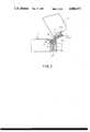
- FIG. 2is a cross-sectional view of an improved hinge unit assembled on a case and a corresponding lid which is located in an open position;
- FIG. 3is a cross-sectional view of an improved hinge unit assembled on a case and a corresponding lid which is located in a closed position;
- FIG. 4is a cross-sectional view of an improved hinge unit assembled on a case and a corresponding lid which is located in a wide open position.
- Each hinge unitcomprises: a pair of bend units 12 having opposed tunnel-shaped passages 121 which run horizontally and terminate by respective side plates 122, are integrally connected to a side wall 10 of a case 1 in spaced apart relation; a receptacle body 11 including a bottom wall 111 having a recess formed therein for retaining the lower end portion 51 of a spring 5 and a circumferential wall extending upward from the periphery of said bottom wall 111, integrally connected to said side wall 10 of the case 1 between and slightly below the bend units 12.
- An openingis formed in the side wall 10 of the case 1 to communicate the inner space of the receptacle body 11 and the opposite side of the side wall 10.
- a guide member 2 having a top plate with a flat top surface and a pair of opposite side platesis slidably inserted in the inner space of the receptacle body 11 and supported by the upper end portion of the spring 5 in a space defined by said top plate opposite side plates of the guide member 2 and the inner side walls of the receptacle body 11.
- a joint plate 3 having a through opening 31 extending transversely through the lower portion which has bottom slope 32 for stably supporting the lid 6 in an open positionis joined with said bend units 12, by means of a pin 4 inserted into said through opening 31 of the plate 3 while the two end portions of pin 4 protruding from the through opening 31 are caught in the tunnel-shaped passages 121 of the bend units 12 as the joint plate 3 is pushed upward by the compressed spring 5 through the guide member 2.
- the joint plate 3further comprises a resilient lock means 33, which has an arrowed top end disposed in a grove 34.
- a socket means 61 having a notch 612 formed in a inner side wall thereof for engaging with the arrowed end of the lock means 33 of the inserted joint plate 3is integrally connected to the side wall of the lid 6.
- the lid 6can be turned between an open position (as shown in FIG. 2) and a closed position (as shown in FIG. 3).
- the bottom slope 32 of the joint plate 3rests on the flat surface of the guide member 2 so that the lid 6 is stably maintained in its open position.
- the spring 5is compressed through the guide member 2 by the lower most end of the joint plate 3, and such facilitates the opening operation of the lid 6.
- a wide open position with a obtuse angle between the case 1 and the lid 6 as shown in FIG. 4can further be reached when necessary.
Landscapes
- Engineering & Computer Science (AREA)
- Mechanical Engineering (AREA)
- Closures For Containers (AREA)
Abstract
Description
1. Field Of The Invention
This invention relates to the design and construction of hinge units for joining a case such as a turntable and its lid.
2. Prior Art
Conventionally, a transparent lid made of plastic or the like is hinged on a side wall of a turntable by means of screws to prevent the accessories such as the platter, the cartridge and so on from dust. The installation of said hinge on the side wall of the turntable and its corresponding lid is labor and time consuming.
Accordingly, it is an object of the present invention to provide improved hinge units for joining a case and its lid which are easy to manufacture, install and operate.
With the above objectives in view, this invention provides improved hinge units for joining a case and its lid which obviate the inconvenience hitherto, the structure of each of which comprises: a pair of bend units with a receptacle body inbetween for keeping a spring, integrally connected to a side wall of a case; a guide member slidably inserted in the hollow space of the receptacle body for retaining the upper portion of the spring; a joint plate having a perforation running transversely through the lower portion thereof to be joined with said bend units by means of an inserted pin; and socket means having a socket for receiving said joint plate integrally connected to a side wall of a lid.
FIG. 1 is an exploded and perspective view of an improved hinge unit and a related case according to the present invention;
FIG. 2 is a cross-sectional view of an improved hinge unit assembled on a case and a corresponding lid which is located in an open position;
FIG. 3 is a cross-sectional view of an improved hinge unit assembled on a case and a corresponding lid which is located in a closed position; and
FIG. 4 is a cross-sectional view of an improved hinge unit assembled on a case and a corresponding lid which is located in a wide open position.
The following is a detailed description of the best presently contemplated embodiment of the invention. This description is not to be taken in a limiting sense, but is made merely for the purpose of illustrating the general principles of the invention.
Referring to FIGS. 1, 2, 3 and 4, the preferred embodiment of improved hinge units for joining a case and its corresponding lid according to the present invention is shown. Each hinge unit comprises: a pair ofbend units 12 having opposed tunnel-shaped passages 121 which run horizontally and terminate byrespective side plates 122, are integrally connected to aside wall 10 of acase 1 in spaced apart relation; areceptacle body 11 including abottom wall 111 having a recess formed therein for retaining thelower end portion 51 of aspring 5 and a circumferential wall extending upward from the periphery ofsaid bottom wall 111, integrally connected to saidside wall 10 of thecase 1 between and slightly below thebend units 12.
An opening is formed in theside wall 10 of thecase 1 to communicate the inner space of thereceptacle body 11 and the opposite side of theside wall 10.
Aguide member 2 having a top plate with a flat top surface and a pair of opposite side plates is slidably inserted in the inner space of thereceptacle body 11 and supported by the upper end portion of thespring 5 in a space defined by said top plate opposite side plates of theguide member 2 and the inner side walls of thereceptacle body 11.
Ajoint plate 3 having a through opening 31 extending transversely through the lower portion which hasbottom slope 32 for stably supporting thelid 6 in an open position is joined with saidbend units 12, by means of apin 4 inserted into said through opening 31 of theplate 3 while the two end portions ofpin 4 protruding from the through opening 31 are caught in the tunnel-shaped passages 121 of thebend units 12 as thejoint plate 3 is pushed upward by thecompressed spring 5 through theguide member 2.
Thejoint plate 3 further comprises a resilient lock means 33, which has an arrowed top end disposed in a grove 34.
A socket means 61 having anotch 612 formed in a inner side wall thereof for engaging with the arrowed end of the lock means 33 of the insertedjoint plate 3 is integrally connected to the side wall of thelid 6.
In operation, thelid 6 can be turned between an open position (as shown in FIG. 2) and a closed position (as shown in FIG. 3). Thebottom slope 32 of thejoint plate 3 rests on the flat surface of theguide member 2 so that thelid 6 is stably maintained in its open position. While thelid 6 is closed, thespring 5 is compressed through theguide member 2 by the lower most end of thejoint plate 3, and such facilitates the opening operation of thelid 6. Certainly, a wide open position with a obtuse angle between thecase 1 and thelid 6 as shown in FIG. 4 can further be reached when necessary.
By the aforementioned construction of the improved hinge units according to the present invention, it can be seen that they have advantages regarding their design and manufacture. These advantages result in decreased manufacturing costs and easy installation and operation.
It will be appreciated, of course, that although a particular embodiment of the invention has been described, modification may be made. It is intended in the following claims to cover all modifications which fall within the scope of the invention.
Claims (2)
1. Improved hinge units for joining a case and a lid, each unit comprising:
a pair of bend units integrally connected to a side wall of said case in spaced apart relation, each of said bend units having tunnel-shaped passages extending horizontally and aligned one with respect to the other;
a receptacle body including a bottom wall and a circumferential wall extending upwardly from the periphery of said bottom wall, said receptacle body being integrally connected to said side wall of the case and positionally located between and slightly below the bend units;
a spring disposed within said receptacle body;
a guide member having a top plate with a flat top surface and at least a pair of opposing side plates, said guide member being slidably received within said receptacle body and supported by said spring;
a joint plate having a through opening formed in a lower portion of said joint plate, said through opening extending transversely through said lower portion of said joint plate, said lower portion of said joint plate including a bottom slope member having a plurality of surfaces, whereby a different one of said surfaces is in contiguous contact with said flat top surface of said guide member top plate responsive to positioning of said lid relative to said case for stably maintaining said lid position, said joint plate having an upper portion wherein there is formed a resilient lock member;
a pin extending through said through opening formed in said lower portion of said joint plate and having opposing ends engaged in said tunnel-shaped passages of the bend units; and
a socket member integrally connected to a side wall of said lid, said socket member having a cavity adapted to receive said upper portion of said joint plate and provide locking engagement with said resilient lock member.
2. The improved hinge units for joining a case and a lid as recited in claim 1 wherein each unit further comprising an opening formed through the side wall of the case to provide open communication between an interior space of the receptacle body and an interior portion of said case.
Priority Applications (2)
| Application Number | Priority Date | Filing Date | Title |
|---|---|---|---|
| GB8816883AGB2220701A (en) | 1989-02-07 | 1988-07-15 | Hinge unit for joining a case and its lid |
| US07/307,049US4884317A (en) | 1989-02-07 | 1989-02-07 | Hinge units for joining a case and its lid |
Applications Claiming Priority (1)
| Application Number | Priority Date | Filing Date | Title |
|---|---|---|---|
| US07/307,049US4884317A (en) | 1989-02-07 | 1989-02-07 | Hinge units for joining a case and its lid |
Publications (1)
| Publication Number | Publication Date |
|---|---|
| US4884317Atrue US4884317A (en) | 1989-12-05 |
Family
ID=23188019
Family Applications (1)
| Application Number | Title | Priority Date | Filing Date |
|---|---|---|---|
| US07/307,049Expired - Fee RelatedUS4884317A (en) | 1989-02-07 | 1989-02-07 | Hinge units for joining a case and its lid |
Country Status (2)
| Country | Link |
|---|---|
| US (1) | US4884317A (en) |
| GB (1) | GB2220701A (en) |
Cited By (34)
| Publication number | Priority date | Publication date | Assignee | Title |
|---|---|---|---|---|
| US5452847A (en)* | 1994-12-22 | 1995-09-26 | United States Corrulite Corporation | Stackable container with recessed hinged lid and hinge means therefor |
| US5500983A (en)* | 1993-05-07 | 1996-03-26 | Mepla Werke Lautenschlager Gmbh & Co. Kg | Corner cabinet hinge |
| GB2338027A (en)* | 1998-06-06 | 1999-12-08 | Norfrost Ltd | Movement arresting hinge |
| US6352295B1 (en)* | 1999-04-27 | 2002-03-05 | American Moto Products, Inc. | Fuel door assembly |
| US6393664B1 (en)* | 1999-09-10 | 2002-05-28 | Mansfield Assemblies Co. | Compression spring hinge mechanism |
| US20030000955A1 (en)* | 2001-05-24 | 2003-01-02 | Young-Gil Lee | Hinge assembly for a door of kimchi storage device |
| US20040117948A1 (en)* | 2002-09-27 | 2004-06-24 | Toshimitsu Ohara | Hinge and image input/output apparatus therewith |
| US20040226138A1 (en)* | 2003-05-16 | 2004-11-18 | Harmon Roger W. | Spring biased hinges and methods therefor |
| US20060284440A1 (en)* | 1999-04-27 | 2006-12-21 | Horst Leitner | Fuel door assembly |
| US20070145871A1 (en)* | 2005-10-04 | 2007-06-28 | Christie Steven J | Hinge System |
| US20090090036A1 (en)* | 2005-08-02 | 2009-04-09 | Ki Ryong Kim | Road Traffic-Control Signboard Assembly Having Automatic Return Function |
| US20100031471A1 (en)* | 2008-08-08 | 2010-02-11 | Hong Fu Jin Precision Industry (Shenzhen) Co., Ltd. | Hinge assembly and foldable electronic device using the same |
| US20100122983A1 (en)* | 2008-11-20 | 2010-05-20 | Steele Michael S | Accessory storage case |
| US8464869B2 (en) | 2011-11-14 | 2013-06-18 | Milwaukee Electric Tool Corporation | Tool case |
| US20130205540A1 (en)* | 2010-05-12 | 2013-08-15 | Nifco Korea Inc. | Hinge device |
| US20150164138A1 (en)* | 2013-04-07 | 2015-06-18 | Kimree Hi-Tech Inc. | Electronic cigarette box and support mechanism |
| USD741681S1 (en) | 2011-07-20 | 2015-10-27 | Milwaukee Electric Tool Corporation | Hand tool |
| US9834259B2 (en) | 2011-06-30 | 2017-12-05 | Lund Motion Products, Inc. | Vehicle bed extender |
| US10173735B2 (en) | 2006-10-27 | 2019-01-08 | Lund Motion Products, Inc. | Vehicle cargo tailgate enclosure |
| WO2019081898A1 (en)* | 2017-10-24 | 2019-05-02 | Nicoventures Holdings Limited | Mechanism for hatch of electronic aerosol provision device |
| US10306087B2 (en)* | 2003-04-30 | 2019-05-28 | Hp Printing Korea Co., Ltd. | Hinge apparatus for cover of image forming apparatus |
| US10399421B2 (en) | 2014-08-06 | 2019-09-03 | Lund Motion Products, Inc. | Tonneau cover and method of attachment |
| US10457124B2 (en) | 2017-08-18 | 2019-10-29 | Roll-N-Lock Corporation | Modified retractable tonneau cover |
| US10800231B2 (en) | 2014-08-04 | 2020-10-13 | Roll-N-Lock Corporation | Retractable truck bed cover having slat array with flexible joiner members and shielded seams |
| US10919369B2 (en) | 2018-04-16 | 2021-02-16 | Lund, Inc. | Clamp assembly for tonneau cover |
| US11220163B2 (en) | 2018-10-26 | 2022-01-11 | Roll-N-Lock Corporation | Vehicle rack assembly |
| US20220144079A1 (en)* | 2020-11-12 | 2022-05-12 | Lund Motion Products, Inc. | Vehicle door assembly |
| US11433953B2 (en) | 2006-10-27 | 2022-09-06 | Lund Motion Products, Inc. | Vehicle cargo tailgate enclosure |
| US11653697B2 (en) | 2017-10-24 | 2023-05-23 | Nicoventures Trading Limited | Electronic aerosol provision device having chassis section and movable hatch section |
| US11654978B2 (en) | 2019-11-04 | 2023-05-23 | Lund Motion Products, Inc. | Vehicle rack assembly |
| US11849767B2 (en) | 2017-10-24 | 2023-12-26 | Nicoventures Trading Limited | Electronic aerosol provision device having chassis section and movable hatch section with sealed sleave |
| US11925205B2 (en) | 2017-10-24 | 2024-03-12 | Nicoventures Trading Limited | Electronic aerosol provision device |
| US12075843B2 (en) | 2017-10-24 | 2024-09-03 | Nicoventures Trading Limited | Device with a hatch selection and a chassis section for an electronic aerosol provision device |
| USD1063794S1 (en) | 2007-10-25 | 2025-02-25 | Lund Motion Products, Inc. | Vehicle tailgate enclosure |
Families Citing this family (1)
| Publication number | Priority date | Publication date | Assignee | Title |
|---|---|---|---|---|
| GB2438408B (en)* | 2006-05-25 | 2010-03-24 | Hoover Ltd | Hinge Assembly |
Citations (1)
| Publication number | Priority date | Publication date | Assignee | Title |
|---|---|---|---|---|
| US4424606A (en)* | 1981-08-10 | 1984-01-10 | Katoh Electrical Machinery Co. Ltd. | Hinge for opening and closing a dust cover |
Family Cites Families (4)
| Publication number | Priority date | Publication date | Assignee | Title |
|---|---|---|---|---|
| IT7620710U1 (en)* | 1976-02-19 | 1977-08-19 | Intertecnica Spa | SELF-BALANCING HINGE, WITH COMPENSATING SPRING, ESPECIALLY FOR FREEZER LIDS AND SIMILAR. |
| WO1981001900A1 (en)* | 1979-12-21 | 1981-07-09 | Kato Electric & Machinary Co | Hinge for opening and closing a dust cover |
| AU537484B2 (en)* | 1980-10-13 | 1984-06-28 | Katoh Electrical Machinery Co., Ltd. | Hinge |
| GB2113291B (en)* | 1982-01-08 | 1985-04-11 | Avo Limited | Hinges |
- 1988
- 1988-07-15GBGB8816883Apatent/GB2220701A/ennot_activeWithdrawn
- 1989
- 1989-02-07USUS07/307,049patent/US4884317A/ennot_activeExpired - Fee Related
Patent Citations (1)
| Publication number | Priority date | Publication date | Assignee | Title |
|---|---|---|---|---|
| US4424606A (en)* | 1981-08-10 | 1984-01-10 | Katoh Electrical Machinery Co. Ltd. | Hinge for opening and closing a dust cover |
Cited By (65)
| Publication number | Priority date | Publication date | Assignee | Title |
|---|---|---|---|---|
| US5500983A (en)* | 1993-05-07 | 1996-03-26 | Mepla Werke Lautenschlager Gmbh & Co. Kg | Corner cabinet hinge |
| US5452847A (en)* | 1994-12-22 | 1995-09-26 | United States Corrulite Corporation | Stackable container with recessed hinged lid and hinge means therefor |
| GB2338027B (en)* | 1998-06-06 | 2002-09-11 | Norfrost Ltd | Hinge |
| GB2338027A (en)* | 1998-06-06 | 1999-12-08 | Norfrost Ltd | Movement arresting hinge |
| US20060284440A1 (en)* | 1999-04-27 | 2006-12-21 | Horst Leitner | Fuel door assembly |
| US6352295B1 (en)* | 1999-04-27 | 2002-03-05 | American Moto Products, Inc. | Fuel door assembly |
| US20030200700A1 (en)* | 1999-04-27 | 2003-10-30 | Horst Leitner | Fuel door assembly |
| US7258386B2 (en) | 1999-04-27 | 2007-08-21 | 89908, Inc. | Fuel door assembly |
| US20050146157A1 (en)* | 1999-04-27 | 2005-07-07 | Horst Leitner | Fuel door assembly |
| US6393664B1 (en)* | 1999-09-10 | 2002-05-28 | Mansfield Assemblies Co. | Compression spring hinge mechanism |
| US20030000955A1 (en)* | 2001-05-24 | 2003-01-02 | Young-Gil Lee | Hinge assembly for a door of kimchi storage device |
| US6766563B2 (en)* | 2001-05-24 | 2004-07-27 | Mando Climate Control Corporation | Hinge assembly for a door of kimchi storage device |
| US20040117948A1 (en)* | 2002-09-27 | 2004-06-24 | Toshimitsu Ohara | Hinge and image input/output apparatus therewith |
| US7069622B2 (en)* | 2002-09-27 | 2006-07-04 | Seiko Epson Corporation | Hinge and image input/output apparatus therewith |
| US20060179611A1 (en)* | 2002-09-27 | 2006-08-17 | Seiko Epson Corporation | Hinge and image input/output apparatus therewith |
| US10306087B2 (en)* | 2003-04-30 | 2019-05-28 | Hp Printing Korea Co., Ltd. | Hinge apparatus for cover of image forming apparatus |
| US7028373B2 (en)* | 2003-05-16 | 2006-04-18 | Motorola, Inc. | Spring biased hinges and methods therefor |
| US20040226138A1 (en)* | 2003-05-16 | 2004-11-18 | Harmon Roger W. | Spring biased hinges and methods therefor |
| US20090090036A1 (en)* | 2005-08-02 | 2009-04-09 | Ki Ryong Kim | Road Traffic-Control Signboard Assembly Having Automatic Return Function |
| US7614173B2 (en)* | 2005-08-02 | 2009-11-10 | Ki Ryong Kim | Road traffic-control signboard assembly having automatic return function |
| US20070145871A1 (en)* | 2005-10-04 | 2007-06-28 | Christie Steven J | Hinge System |
| US7934782B2 (en)* | 2005-10-04 | 2011-05-03 | Christie Steven J | Hinge system |
| US10518821B2 (en) | 2006-10-27 | 2019-12-31 | Lund Motion Products, Inc. | Vehicle cargo tailgate enclosure |
| US11142263B2 (en) | 2006-10-27 | 2021-10-12 | Lund Motion Products, Inc. | Vehicle tailgate enclosure |
| US10173735B2 (en) | 2006-10-27 | 2019-01-08 | Lund Motion Products, Inc. | Vehicle cargo tailgate enclosure |
| US11970217B2 (en) | 2006-10-27 | 2024-04-30 | Lund Motion Products, Inc. | Vehicle cargo tailgate enclosure |
| US11724753B2 (en) | 2006-10-27 | 2023-08-15 | Lund Motion Products. Inc. | Vehicle cargo tailgate enclosure |
| US11433953B2 (en) | 2006-10-27 | 2022-09-06 | Lund Motion Products, Inc. | Vehicle cargo tailgate enclosure |
| USD1063794S1 (en) | 2007-10-25 | 2025-02-25 | Lund Motion Products, Inc. | Vehicle tailgate enclosure |
| US20100031471A1 (en)* | 2008-08-08 | 2010-02-11 | Hong Fu Jin Precision Industry (Shenzhen) Co., Ltd. | Hinge assembly and foldable electronic device using the same |
| US8096020B2 (en)* | 2008-08-08 | 2012-01-17 | Hong Fu Jin Precision Industry (Shenzhen) Co., Ltd. | Hinge assembly and foldable electronic device using the same |
| US8342345B2 (en) | 2008-11-20 | 2013-01-01 | Milwaukee Electric Tool Corporation | Accessory storage case |
| US20100122983A1 (en)* | 2008-11-20 | 2010-05-20 | Steele Michael S | Accessory storage case |
| US8850660B2 (en)* | 2010-05-12 | 2014-10-07 | Nifco Korea Inc. | Hinge device |
| US20130205540A1 (en)* | 2010-05-12 | 2013-08-15 | Nifco Korea Inc. | Hinge device |
| US9834259B2 (en) | 2011-06-30 | 2017-12-05 | Lund Motion Products, Inc. | Vehicle bed extender |
| US10457337B2 (en) | 2011-06-30 | 2019-10-29 | Lund Motion Products, Inc. | Vehicle bed extender |
| USD741681S1 (en) | 2011-07-20 | 2015-10-27 | Milwaukee Electric Tool Corporation | Hand tool |
| US8464869B2 (en) | 2011-11-14 | 2013-06-18 | Milwaukee Electric Tool Corporation | Tool case |
| US20150164138A1 (en)* | 2013-04-07 | 2015-06-18 | Kimree Hi-Tech Inc. | Electronic cigarette box and support mechanism |
| EP2984949A4 (en)* | 2013-04-07 | 2016-12-21 | Kimree Hi-Tech Inc | Electronic cigarette case and support structure thereof |
| US10800231B2 (en) | 2014-08-04 | 2020-10-13 | Roll-N-Lock Corporation | Retractable truck bed cover having slat array with flexible joiner members and shielded seams |
| US11634014B2 (en) | 2014-08-04 | 2023-04-25 | Roll-N-Lock Corporation | Retractable truck bed cover having slat array with flexible joiner members and shielded seams |
| US11072227B2 (en) | 2014-08-06 | 2021-07-27 | Lund Motion Products, Inc. | Tonneau cover and method of attachment |
| US10399421B2 (en) | 2014-08-06 | 2019-09-03 | Lund Motion Products, Inc. | Tonneau cover and method of attachment |
| US11697332B2 (en) | 2017-08-18 | 2023-07-11 | Roll-N-Lock Corporation | Modified retractable tonneau cover |
| US10457124B2 (en) | 2017-08-18 | 2019-10-29 | Roll-N-Lock Corporation | Modified retractable tonneau cover |
| US12172505B2 (en) | 2017-08-18 | 2024-12-24 | Roll-N-Lock Corporation | Modified retractable tonneau cover |
| US11040605B2 (en) | 2017-08-18 | 2021-06-22 | Roll-N-Lock Corporation | Modified retractable tonneau cover |
| CN111278310B (en)* | 2017-10-24 | 2023-02-28 | 尼科创业贸易有限公司 | Mechanism for hatch of electronic aerosol provision device |
| US12075843B2 (en) | 2017-10-24 | 2024-09-03 | Nicoventures Trading Limited | Device with a hatch selection and a chassis section for an electronic aerosol provision device |
| US11653697B2 (en) | 2017-10-24 | 2023-05-23 | Nicoventures Trading Limited | Electronic aerosol provision device having chassis section and movable hatch section |
| WO2019081898A1 (en)* | 2017-10-24 | 2019-05-02 | Nicoventures Holdings Limited | Mechanism for hatch of electronic aerosol provision device |
| CN111278310A (en)* | 2017-10-24 | 2020-06-12 | 尼科创业贸易有限公司 | Mechanism for the hatch of an electronic aerosol supply device |
| US11849767B2 (en) | 2017-10-24 | 2023-12-26 | Nicoventures Trading Limited | Electronic aerosol provision device having chassis section and movable hatch section with sealed sleave |
| US11925205B2 (en) | 2017-10-24 | 2024-03-12 | Nicoventures Trading Limited | Electronic aerosol provision device |
| US11930851B2 (en) | 2017-10-24 | 2024-03-19 | Nicoventures Trading Limited | Electronic aerosol provision device having a chassis section and a movable hatch section with a sealed sleeve |
| US12161155B2 (en) | 2017-10-24 | 2024-12-10 | Nicoventures Trading Limited | Electronic aerosol provision system |
| US10919369B2 (en) | 2018-04-16 | 2021-02-16 | Lund, Inc. | Clamp assembly for tonneau cover |
| US11654755B2 (en) | 2018-10-26 | 2023-05-23 | Roll-N-Lock Corporation | Vehicle rack assembly |
| US11220163B2 (en) | 2018-10-26 | 2022-01-11 | Roll-N-Lock Corporation | Vehicle rack assembly |
| US11654978B2 (en) | 2019-11-04 | 2023-05-23 | Lund Motion Products, Inc. | Vehicle rack assembly |
| US11964702B2 (en) | 2019-11-04 | 2024-04-23 | Lund Motion Products, Inc. | Vehicle rack assembly |
| US11332004B1 (en)* | 2020-11-12 | 2022-05-17 | Lund Motion Products, Inc. | Vehicle door assembly |
| US20220144079A1 (en)* | 2020-11-12 | 2022-05-12 | Lund Motion Products, Inc. | Vehicle door assembly |
Also Published As
| Publication number | Publication date |
|---|---|
| GB8816883D0 (en) | 1988-08-17 |
| GB2220701A (en) | 1990-01-17 |
Similar Documents
| Publication | Publication Date | Title |
|---|---|---|
| US4884317A (en) | Hinge units for joining a case and its lid | |
| US4955478A (en) | Flip-top drill-bit storage and display box | |
| KR900008923A (en) | Battery storage devices | |
| US5508124A (en) | Confined battery door | |
| US6286671B1 (en) | Case for holding two compact discs | |
| KR920010109A (en) | Hinged housing | |
| US6314691B1 (en) | Inspection opening frame | |
| US2474311A (en) | Hinged casing structure | |
| US5355556A (en) | Enclosure having reversible door and hinge therefor | |
| US5890261A (en) | Door handle bases for mounting door handles to doors | |
| KR960007237B1 (en) | Video cassette dust door latch | |
| CN215056349U (en) | Miniaturized locking device | |
| US5032956A (en) | Lamp cover assembly for electric appliances | |
| US5334052A (en) | Receptacle | |
| US3498659A (en) | Multisection casing and latch mechanism therefor | |
| KR100513556B1 (en) | Luggage box | |
| KR200193251Y1 (en) | A hinge structure for doors | |
| US5494260A (en) | Staple remover | |
| JPS6033171Y2 (en) | Manhole cover attachment device | |
| US4845968A (en) | Combination lock | |
| JPH0720035Y2 (en) | box | |
| JPH09293977A (en) | Electronic equipment outer case | |
| KR940001967Y1 (en) | Center hinge of cold storage | |
| JPH04128256U (en) | Case with removable cover | |
| KR200148766Y1 (en) | Partition support device for custody box |
Legal Events
| Date | Code | Title | Description |
|---|---|---|---|
| FPAY | Fee payment | Year of fee payment:4 | |
| SULP | Surcharge for late payment | ||
| REMI | Maintenance fee reminder mailed | ||
| REFU | Refund | Free format text:REFUND - PAYMENT OF MAINTENANCE FEE, 8TH YR, SMALL ENTITY (ORIGINAL EVENT CODE: R284); ENTITY STATUS OF PATENT OWNER: SMALL ENTITY | |
| FPAY | Fee payment | Year of fee payment:8 | |
| REMI | Maintenance fee reminder mailed | ||
| LAPS | Lapse for failure to pay maintenance fees | ||
| STCH | Information on status: patent discontinuation | Free format text:PATENT EXPIRED DUE TO NONPAYMENT OF MAINTENANCE FEES UNDER 37 CFR 1.362 | |
| FP | Lapsed due to failure to pay maintenance fee | Effective date:20011205 |