US4883982A - Electronically commutated motor, blower integral therewith, and stationary and rotatable assemblies therefor - Google Patents
Electronically commutated motor, blower integral therewith, and stationary and rotatable assemblies thereforDownload PDFInfo
- Publication number
- US4883982A US4883982AUS07/201,681US20168188AUS4883982AUS 4883982 AUS4883982 AUS 4883982AUS 20168188 AUS20168188 AUS 20168188AUS 4883982 AUS4883982 AUS 4883982A
- Authority
- US
- United States
- Prior art keywords
- assembly
- support member
- stationary
- air
- rotatable
- Prior art date
- Legal status (The legal status is an assumption and is not a legal conclusion. Google has not performed a legal analysis and makes no representation as to the accuracy of the status listed.)
- Expired - Lifetime
Links
Images


Classifications
- H—ELECTRICITY
- H02—GENERATION; CONVERSION OR DISTRIBUTION OF ELECTRIC POWER
- H02K—DYNAMO-ELECTRIC MACHINES
- H02K7/00—Arrangements for handling mechanical energy structurally associated with dynamo-electric machines, e.g. structural association with mechanical driving motors or auxiliary dynamo-electric machines
- F—MECHANICAL ENGINEERING; LIGHTING; HEATING; WEAPONS; BLASTING
- F04—POSITIVE - DISPLACEMENT MACHINES FOR LIQUIDS; PUMPS FOR LIQUIDS OR ELASTIC FLUIDS
- F04D—NON-POSITIVE-DISPLACEMENT PUMPS
- F04D29/00—Details, component parts, or accessories
- F04D29/26—Rotors specially for elastic fluids
- F04D29/28—Rotors specially for elastic fluids for centrifugal or helico-centrifugal pumps for radial-flow or helico-centrifugal pumps
- F04D29/281—Rotors specially for elastic fluids for centrifugal or helico-centrifugal pumps for radial-flow or helico-centrifugal pumps for fans or blowers
- F—MECHANICAL ENGINEERING; LIGHTING; HEATING; WEAPONS; BLASTING
- F04—POSITIVE - DISPLACEMENT MACHINES FOR LIQUIDS; PUMPS FOR LIQUIDS OR ELASTIC FLUIDS
- F04D—NON-POSITIVE-DISPLACEMENT PUMPS
- F04D25/00—Pumping installations or systems
- F04D25/02—Units comprising pumps and their driving means
- F04D25/08—Units comprising pumps and their driving means the working fluid being air, e.g. for ventilation
- F—MECHANICAL ENGINEERING; LIGHTING; HEATING; WEAPONS; BLASTING
- F04—POSITIVE - DISPLACEMENT MACHINES FOR LIQUIDS; PUMPS FOR LIQUIDS OR ELASTIC FLUIDS
- F04D—NON-POSITIVE-DISPLACEMENT PUMPS
- F04D29/00—Details, component parts, or accessories
- F04D29/58—Cooling; Heating; Diminishing heat transfer
- F04D29/582—Cooling; Heating; Diminishing heat transfer specially adapted for elastic fluid pumps
- H—ELECTRICITY
- H02—GENERATION; CONVERSION OR DISTRIBUTION OF ELECTRIC POWER
- H02K—DYNAMO-ELECTRIC MACHINES
- H02K11/00—Structural association of dynamo-electric machines with electric components or with devices for shielding, monitoring or protection
- H02K11/30—Structural association with control circuits or drive circuits
- H02K11/33—Drive circuits, e.g. power electronics
- H—ELECTRICITY
- H02—GENERATION; CONVERSION OR DISTRIBUTION OF ELECTRIC POWER
- H02K—DYNAMO-ELECTRIC MACHINES
- H02K9/00—Arrangements for cooling or ventilating
- H02K9/02—Arrangements for cooling or ventilating by ambient air flowing through the machine
- H02K9/04—Arrangements for cooling or ventilating by ambient air flowing through the machine having means for generating a flow of cooling medium
- H02K9/06—Arrangements for cooling or ventilating by ambient air flowing through the machine having means for generating a flow of cooling medium with fans or impellers driven by the machine shaft
Definitions
- This inventionrelates in general to dynamoelectric machines and application systems for such machines. More particularly, this invention relates to an electronically commutated motor and electronically commutated motor with integral blower apparatus.
- While conventional brush-commutated DC motorsmay have advantageous characteristics, including convenience of changing operational speeds, there may be disadvantages such as brush wear, electrical loss, noise and radio frequency interference caused by sparking between the brushes and the segmented commutator, which may limit the applicability of such brush-commutated DC motors in some fields such as the vehicular blower control field.
- Electronically commutated motorssuch as brushless DC motors and permanent magnet motors with electronic commutation, have now been developed and generally are believed to have the above-discussed advantageous characteristics of the brush-commutated DC motors without many of the disadvantages thereof while also having other important advantages.
- Such electronically commutated motorsare disclosed in the David M. Erdman U.S. Pat. Nos. 4,015,182 and 4,459,519 for instance. These electronically commutated motors are advantageously employed, for instance, commutated motors in air conditioning for cooling and warming of vehicular compartments.
- variable resistancecan be used to vary the speed of a brush-type blower motor, but this would further reduce the energy efficiency of the system. While there are some losses engendered by electronic switching of an electronically commutated motor, these are negligible compared to brush losses and rheostat losses in prior art variable speed blower systems.
- the control circuitry required to electronically commutate a brushless DC motoris typically mounted remote from the motor in a location where the circuitry can be adequately cooled and unaffected by motor heat.
- a dedicated cooling mechanismsuch as a fan wheel is generally employed to provide the required heat dissipation, i.e., the mechanism is provided primarily for the purpose of cooling the control circuitry.
- the control circuitrymay be mounted on a printed circuit board on the stator and cooled by air moved by the blower assembly.
- the dedicated cooling mechanismresults in additional cost and failure of such mechanism results in added maintenance expenses.
- the control circuitrymay not be sufficiently cooled and may not be accessed for repair or maintenance without disassembly of the motor.
- an improved electronically commutated motor and improved electronically commutated motor and blower apparatuswhich overcome at least some of the disadvantageous conditions discussed above; the provision of an improved electronically commutated motor and an improved electronically commutated motor and blower apparatus which substantially dissipate motor heat and adequately cool the control circuitry; the provision of an improved electronically commutated motor and an improved electronically commutated motor and blower apparatus which are reliable, economical and convenient to use; the provision of an improved electronically commutated motor with integral blower apparatus and integral control circuitry cooled by the movement of air caused by said integral blower apparatus.
- one form of the inventionis a motor assembly comprising a support member adapted to be mounted on a stationary support for supporting the motor assembly and having first and second opposite sides.
- a stationary assemblyis mounted on the first side of the support member and has a plurality of winding stages adapted to be electrically energized to generate an electromagmetic field.
- An annular rotatable assemblyincluding a plurality of permanent magnet elements surrounds said stationary assembly.
- Control meansconnected to the winding stages and positioned on the second side of said support member, applies a voltage to one or more of the winding stages at a time and commutates the winding stages in a preselected sequence to rotate the rotatable assembly.
- the inventionis a motor assembly comprising a support member adapted to be mounted on a stationary support for supporting said motor assembly.
- An annular rotatable assemblyincludes a housing supporting a plurality of permanent magnet elements and means on the housing located between the housing and the support member for moving air from a central area of the annular rotatable assembly to a peripheral area thereof.
- a stationary assemblyis mounted on the support member and within and supporting the rotatable assembly, the stationary assembly having a plurality of winding stages adapted to be electrically energized to generate an electromagnetic field for rotating the rotatable assembly.
- Another form of the inventionis a rotatable assembly for use in a dynamoelectric machine.
- the assemblycomprises a housing having a peripheral portion.
- a plurality of permanent magnet elementsare positioned around the peripheral portion of the housing.
- Impeller means, on the housing,moves air about the dynamoelectric machine as the rotatable assembly is caused to rotate.
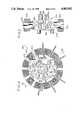
- FIG. 1is an axial cross-sectional view of the electronically commutated brushless DC motor of the invention in combination with a squirrel cage blower attached to the front end of the motor taken along lines 1--1 FIG. 1A;
- FIG. 1Ais a front plan view of the support member of the motor of the invention.
- FIG. 2is a rear plan view of the motor of the invention illustrated in FIG. 1 with some parts which are located under the end cap shown in phantom;
- FIG. 3is a partial cross-sectional view of the motor of the invention taken along lines 3--3 of FIG. 2;
- FIG. 4is a plan view of the stationary assembly of the motor of the invention.
- reference character 100generally designates a brushless electronically commutated DC motor comprising stationary assembly 200 located at the center of the motor and an annular rotatable assembly 300 which surrounds the stationary assembly.
- An annular squirrel cage fan 102 or other means for moving air through an air handling systemengages and is mounted on rotatable assembly 300 and is adapted to be rotatably driven thereby.
- motor assembly 100is for use in combination with an air handling system such as an automotive blower system for supplying cooled or heated air to a passenger compartment of an automobile.
- Stationary assembly 200comprises a plurality of winding stages 202 adapted to be electrically energized to generate an electromagnetic field. Stages 202 are coils of wire wound around the teeth of laminated stator core 204 having a central opening within which bearing housing 206 is mounted. Bearing housing 206, in turn, is mounted on support member 208 by a plurality of internally threaded bosses 272 which engage a threaded end of stand-off studs 210. Elastomeric grommets 212 resiliently support stationary assembly 200 and separate the bosses 272 of bearing housing 206 from support member 208 for noise isolation. As shown in FIGS.
- Rotatable assembly 300comprises a plurality of radially magnetized permanent magnet segments 302 which combine to form a ring secured to the inner periphery of edgewise wound rotor flux ring 304 and aligned with stator core 204. Segments 302 constitute magnetic elements of annular rotatable assembly 300 which surround stationary assembly 200.
- Rotor flux ring 304is secured to and integral with molded annular housing 306 which, in turn, is integral with radial rotor wall 308.
- a plurality of radial arcuate vanes 310extend from central rotor hub 312 to rotor wall 308.
- motor assembly 100including printed circuit board 400, is enclosed in end cap 406 which is mounted on and supported by support member 208 via fastening screws 408.
- end cap 406is mounted on the rear portion of motor assembly 100 and encloses the control means of the motor between cap 406 and support member 208. Portions of the control means are shown in FIG. 2 in phantom.
- Radial flange 218 of support member 208is located along the circumference of end cap 406. As shown in FIGS. 1A and 2, radial flange 218 includes notches 230 in which fasteners such as bolts may be located for engaging stationary support member 220 (shown in FIG. 1).
- Openings 418, 420, 422, and 424are adjacent heat sinks 404 so that air drawn in through these openings is directed over the heat sinks 404.
- U-shaped air director 226includes substantially parallel legs 230 and 232 mounted on and perpendicular to base 234 and parallel to the legs of heat sinks 404.
- Base 234is mounted on support member 208 such that heat sinks 404 are located between legs 230 and 232.
- Each heat sinkincludes legs 436 and 438 parallel to each other and perpendicularly connected to base 440.
- Power transistor 402is located in an indentation of heat sink 404 and is held in place by opposing projection 442.
- transistor 402is connected to printed circuit board 400 by conductor 444.
- stationary assembly 200is illustrated as having a wheel-like construction including bearing housing 206 press-fitted into laminated stator core 204.
- the bearing housingincludes a central hub 252 integral with a plurality of regularly spaced apart radial struts 254 which, like spokes of a wheel, support the central hub 252 coaxially within outer rim 256.
- Central hub 252defines a bore 224 for receiving the rotor shaft.
- bore 224is defined by cylindric bearing members 258, 260, each having an axial opening therein adapted to receive the rotor shaft, and coaxially held in place by radial positioning members 262 which extend the length of the hub.
- Radial positioning members 262are spaced at regular intervals around the hub and apertures 266 between adjacent members are filled with means for lubricating such as a lubricant-soaked packing material 280 for lubricating bore 224 so that the means for lubricating surrounds the bearing members.
- Lubricantis permitted to flow into bore 224 between bore 224 and rotor shaft 313 via gap 264 between the bearing members 258 and 260 shown in FIG. 5.
- oil thrower washers 281 and 282 and seals 283 and 284retain the lubricant within packing material 280.
- Screw 285 and washer 286retain rotor shaft 313 with rotatable housing 300.
- a plurality of apertures 267are formed by adjacent radial struts 254, central hub 252 and outer rim 256 at regularly spaced apart intervals. Apertures 267 are in communication with openings 225,227,229 to permit air to flow through the stationary assembly 200. Apertures 267 are regularly spaced around bore 224.
- core 204is provided with a plurality of axial grooves 268 spaced at regular intervals which function as keyways for keys which are formed from the outer rim 256 by deforming a portion 270 thereof into grooves 268.
- the laminated stator core 204defines a plurality of teeth having slots therebetween, such as the twelve teeth and slots illustrated in FIG. 4. Each tooth carries a coil of wire received in the slot which forms a portion of a winding stage of stationary assembly 200. In the embodiment illustrated in FIG. 4, it is contemplated that three winding stages may be provided, one stage wound around the first, fourth, seventh and tenth teeth, a second stage wound around the second, fifth, eighth and eleventh teeth and a third stage wound around the remaining teeth.
- bearing housing 206also includes internally threaded bosses 272 for supporting stationary assembly 200.
- Bosses 272are integral with the outer rim 256 and parallel to the central axis A--A and the coaxial axis of central hub 252.
- stand-off studs 210are rods threaded at each end thereof, with one end engaging the internal threads of bosses 272 and the other end engaging a nut 274 for securing printed circuit board 400 onto stud 210.
- Stud 210is also provided with ridge 274 for supporting circuit board 400 and ridge 276 for retaining washer 278 against boss 272.
- Washer 280is located at the base of boss 272.
- elastomeric grommet 212 or other elastomeric memberis sandwiched and located within an opening in support member 208 to provide a vibration isolation mounting between the support member 208 and the remainder of motor assembly 100 and to resiliently support board 400 as well as stationary assembly 200.
- Grommet 212has a coaxial bore for receiving boss 272.
- a plurality of radial arcuate vanes 310extend from the central rotor hub 312 to the outer edge of peripheral flange 314 extending in a radial plane with respect to the rotor. Vanes 310 are curved in the direction of rotation as indicated by arrow 316 as it is rotated by the electromagnetic field generated by stationary assembly 200. Vanes 310 move air from central hub 312 (a central area of rotatable assembly 300) toward peripheral flange 314 (a peripheral area of rotatable assembly 300) as indicated by arrows 318.
- the annular rotatable assembly 300is preferably molded of a glass-reinforced synthetic resin such as TEMPALLOY (Trade Mark) and may include a plurality of solid posts 320 integral with vanes 310.
- Posts 320provide additional support to each of the radial arcuate vanes 310, can function as ejection pins during the molding process, and also provide mass to the rotor which may be selectively removed in order to balance the rotor, i.e., posts 320 may be filed, sanded, cut or otherwise reduced in size to balance rotatable assembly 300.
- cylindrical reinforcing member 322which reinforces hub 312 and securely and firmly engages rotor shaft 313.
- Member 322may be provided with radial flange 324 which is also molded within the hub 312 to add additional strength and rigidity to, hub 312.
- molded annular rotor housing 306,which encloses the edgewise wound flux ring 304 (shown in FIG. 1), is provided with a plurality of fins 326 spaced at close, regular intervals on the rear face of housing 306. Fins 326 extend generally circumferentially and are directed slightly radially inwardly. Fins 336 constitute impeller means on a second or rear side of rotatable assembly 300 for moving air over board 400 and through openings 225,227,229 in heat exchange relationship to board 400. Arrow 332 indicates the direction of rotation of annular rotatable assembly 300 as it is rotated by the electromagnetic field generated by stationary assembly 200.
- fins 326are positioned to move air from central hub 312 (a central area of rotatable assembly 300) toward peripheral flange 314 (a peripheral area of rotatable assembly 300) as indicated by arrow 334.
- Fins 326may be provided with an inner end 336 and an outer end 338, inner and outer referring to the relative position of the flange with respect to the central axis A--A of the motor assembly.
- outer end 338is provided with a reduced axial dimension, i.e., reduced width in order to provide clearance between the fins and support member 208 yet provide maximum surface area to facilitate air movement toward the periphery of the annular rotatable assembly 300.
- Fins 326are an integral portion of the molded annular housing 306.
- molded annular housing 306Positioned immediately radially inwardly from molded annular housing 306 and preferably in contact with the flux ring within housing 306 are four arcuate magnet segments 302 alternately radially polarized to form eight (8) poles as indicated by S for south and N for north.
- the front surface of magnets 302abut against the molded housing 306 which forms an internal circular shoulder 330 terminating in radial wall 328.
- Vanes 310are substantially perpendicular to wall 308 and shoulder 330 as well as perpendicular to peripheral flange 314.
- Apertures 315 within rotatable assembly 300are formed by vanes 310, the inner circumferential edge 309 of wall 308 and the outer circumference of central rotor hub 312. Apertures 315, apertures 267 in stationary assembly 200, openings 225,227,229 in support member 208 and air inlet 416 are in communication with each other to permit air flow from inlet 416 to outlet 502.
- the motor assembly 100operates in the following manner.
- four connectorsare connected to PC board 400, two connectors supply DC power to PC board 400 and two connectors supply a DC signal to boar 400 indicating the desired torque or operating speed of motor assembly 100.
- End cap 406may have an integral receptacle connected to PC board 400 for receiving a plug or other fixture.
- a wiring harnessmay be connected to board 400 and pass through an aperture in end cap 406, the wire harness terminating in a connector for connection to the automotive blower control system.
- the control circuitry of board 400selectively applies a DC voltage to the winding stages of stationary assembly 200 and commutates the winding stages to rotate the rotatable assembly 300 thereby rotating the annular squirrel cage fan 102 and moving air through the automotive air handling system.
- rotatable assembly 300rotates, air between adjacent radial arcuate vanes 310 is forced from the central hub 312 toward the peripheral flange 314 as indicated by arrow 500 in FIG. 1.
- the gap 502 between the stationary support member 220 and the outer peripheral edge of vane 310forms an outlet which supplies the air pumped by vanes 310 as indicated by arrow 504.
- Air inlet 416, openings 225,227,229, apertures 254, apertures 267 and gap 502are in communication with each other to permit continuous air flow therethrough, i.e., they are aligned to facilitate air flow as indicated by the arrows. Some of the air will be directed as indicated by arrow 506 through opening 227 and then, as indicated by arrow 508, through the apertures formed between radial struts 254 and finally through apertures 267 formed by vanes 310 as indicated by arrow 510.
- annular squirrel cage fan 102also rotates to create a pressure differential assisting in movement of the air from the center of the motor assembly 100 toward the periphery thereof. It is contemplated that the squirrel cage fan would pump approximately 250 cubic feet per minute (C.F.M) of air within the automobile air handling system and that vanes 310 would move approximately 25 C.F.M. over the heat sinks 404 to cool the power transistors 402 at about 3000 r.p.m. of motor 100.
- C.F.Mcubic feet per minute
- fins 326are provided and constitute means on the rotatable assembly for inhibiting air on the first side 222 of support member 208 flowing back through inlet openings 225,227,229 to the second side 224 of support member 208. Fins 326 are sized and angled to inhibit air movement between support member 208 and the stationary and rotatable assemblies from outlet 502 to the openings in the support member. If desired, fins 326 may be configured to move such air toward outlet 502.
- openings 225,227,229are adapted to permit air on the second side 224 to flow therethrough to the first side.
- Approximately a 10% loss in air flow volume or 25 C.F.Mcan result if no means, such as fins 326, are provided to inhibit this back flow of air.
- annular rotatable assembly 300is provided with means on the front side thereof in the form of vanes 310 and means on the rear side thereof in the form of fins 326 for moving air from the center of rotatable assembly 300 toward its periphery.
- the actual volume of air which is pumped through the automobile air handling system by squirrel cage fan 102 and the volume of air pumped by rotatable assembly 300 through air inlet 416depends upon the speed or torque of the motor 100 and the resistance flow within the air handling system.
- the resistance to flowdepends, in part, on the mode of operation. For example, the air flow through the condenser coils of a compressor may encounter a different resistance than the air flow through a heating coil.
- the surface area and directional pitch of vanes 310 and fins 326should be adjusted as required to meet the needs of the particular air handling system with which motor 100 is used.
Landscapes
- Engineering & Computer Science (AREA)
- Mechanical Engineering (AREA)
- General Engineering & Computer Science (AREA)
- Power Engineering (AREA)
- Thermal Sciences (AREA)
- Physics & Mathematics (AREA)
- Microelectronics & Electronic Packaging (AREA)
- Motor Or Generator Cooling System (AREA)
- Structures Of Non-Positive Displacement Pumps (AREA)
- Brushless Motors (AREA)
- Motor Or Generator Frames (AREA)
- Connection Of Motors, Electrical Generators, Mechanical Devices, And The Like (AREA)
- Permanent Magnet Type Synchronous Machine (AREA)
- Reciprocating, Oscillating Or Vibrating Motors (AREA)
Abstract
Description
Claims (40)
Priority Applications (6)
| Application Number | Priority Date | Filing Date | Title |
|---|---|---|---|
| US07/201,681US4883982A (en) | 1988-06-02 | 1988-06-02 | Electronically commutated motor, blower integral therewith, and stationary and rotatable assemblies therefor |
| CA000597135ACA1305994C (en) | 1988-06-02 | 1989-04-19 | Electronically commutated motor, blower integral therewith, and stationary and rotable assemblies therefor |
| DE3917040ADE3917040A1 (en) | 1988-06-02 | 1989-05-25 | ELECTRONICALLY COMMUTED MOTOR, THEREFORE INTEGRATED BLOWER AND STATIONARY AND ROTATABLE ARRANGEMENTS THEREFOR |
| KR1019890007592AKR900001089A (en) | 1988-06-02 | 1989-06-02 | Electric rectifier motors, blowers integrated therewith, and fixed and rotary assemblies thereof |
| JP1139410AJPH0236756A (en) | 1988-06-02 | 1989-06-02 | Electronic commutation type motor, the motor unified with blower and stational and turnable assembly of the motor |
| MX016311AMX168085B (en) | 1988-06-02 | 1989-06-02 | ELECTRONICALLY SWITCHED MOTOR, INTEGRAL BLOWER WITH THE SAME, AND STATIONARY AND ROTARY ASSEMBLIES FOR THE SAME |
Applications Claiming Priority (1)
| Application Number | Priority Date | Filing Date | Title |
|---|---|---|---|
| US07/201,681US4883982A (en) | 1988-06-02 | 1988-06-02 | Electronically commutated motor, blower integral therewith, and stationary and rotatable assemblies therefor |
Publications (1)
| Publication Number | Publication Date |
|---|---|
| US4883982Atrue US4883982A (en) | 1989-11-28 |
Family
ID=22746846
Family Applications (1)
| Application Number | Title | Priority Date | Filing Date |
|---|---|---|---|
| US07/201,681Expired - LifetimeUS4883982A (en) | 1988-06-02 | 1988-06-02 | Electronically commutated motor, blower integral therewith, and stationary and rotatable assemblies therefor |
Country Status (6)
| Country | Link |
|---|---|
| US (1) | US4883982A (en) |
| JP (1) | JPH0236756A (en) |
| KR (1) | KR900001089A (en) |
| CA (1) | CA1305994C (en) |
| DE (1) | DE3917040A1 (en) |
| MX (1) | MX168085B (en) |
Cited By (77)
| Publication number | Priority date | Publication date | Assignee | Title |
|---|---|---|---|---|
| US5093891A (en)* | 1989-11-13 | 1992-03-03 | Mitsubishi Denki Kabushiki Kaisha | Brushless motor and an axial flow fan with the brushless motor |
| GB2251028A (en)* | 1990-12-21 | 1992-06-24 | Black & Decker Inc | Cooling electric motor with a radial-flow fan |
| US5164626A (en)* | 1990-06-14 | 1992-11-17 | Fujikura Ltd. | Coil element and heat generating motor assembled therefrom |
| US5245237A (en)* | 1992-03-19 | 1993-09-14 | General Electric Company | Two compartment motor |
| US5383679A (en)* | 1992-03-04 | 1995-01-24 | Unisia Jecs Corporation | Arrangement of suspension system for automotive vehicle |
| US5394041A (en)* | 1989-07-14 | 1995-02-28 | Wap Reinigungssysteme Gmbh & Co. | Electronically commutated motor for dust exhausters, vacuum cleaners and similar devices |
| US5454690A (en)* | 1994-01-13 | 1995-10-03 | Shop Vac Corporation | Air flow housing |
| GB2292185A (en)* | 1994-08-06 | 1996-02-14 | Kuo Chung Li | Fan with air cooling means |
| US5532534A (en)* | 1994-05-11 | 1996-07-02 | Emerson Electric Co. | Brushless permanent magnet condenser motor for refrigeration |
| US5574321A (en)* | 1994-05-04 | 1996-11-12 | Emerson Electric Co. | Integral refrigerator motor fan blades |
| FR2745441A1 (en)* | 1996-02-22 | 1997-08-29 | Bosch Gmbh Robert | BLOWER MOTOR |
| US5675464A (en)* | 1996-05-02 | 1997-10-07 | Siemens Electric Limited | Stall or reduced-speed protection system for electric motor |
| EP0802611A1 (en)* | 1996-04-19 | 1997-10-22 | Siemens Electric Limited | Brushless motor with tubular bearing support |
| US5744921A (en)* | 1996-05-02 | 1998-04-28 | Siemens Electric Limited | Control circuit for five-phase brushless DC motor |
| US5757101A (en)* | 1995-06-06 | 1998-05-26 | International Business Machines Corporation | Laminated back iron structrue for increased motor efficiency |
| US5763969A (en)* | 1996-11-14 | 1998-06-09 | Reliance Electric Industrial Company | Integrated electric motor and drive system with auxiliary cooling motor and asymmetric heat sink |
| US5789834A (en)* | 1995-05-08 | 1998-08-04 | Matsushita Electric Industrial Co., Ltd. | Spindle motor |
| US5825107A (en)* | 1997-06-13 | 1998-10-20 | General Electric Company | Drive package for a dynamoelectric machine |
| FR2776140A1 (en)* | 1998-03-16 | 1999-09-17 | Asmo Co Ltd | Brushless electrical motor for an automobile air conditioning fan |
| US5967764A (en)* | 1997-08-08 | 1999-10-19 | Bosch Automotive Systems Corporation | Axial fan with self-cooled motor |
| US6129524A (en)* | 1998-12-07 | 2000-10-10 | Turbodyne Systems, Inc. | Motor-driven centrifugal air compressor with axial airflow |
| US6208052B1 (en)* | 1999-08-18 | 2001-03-27 | Siemens Canada Limited | Cooling module for an electronically controlled engine |
| US6236126B1 (en)* | 1999-06-25 | 2001-05-22 | Calsonic Kansei Corporation | Brushless motor |
| US6356005B1 (en)* | 2001-06-27 | 2002-03-12 | Chun-Pu Hsu | Wheel drum structure of inner stator portion with an inbuilt driving control circuit |
| WO2002020994A1 (en)* | 2000-09-07 | 2002-03-14 | Stribel Gmbh | Electric ventilator |
| US6384494B1 (en)* | 1999-05-07 | 2002-05-07 | Gate S.P.A. | Motor-driven fan, particularly for a motor vehicle heat exchanger |
| WO2002078149A1 (en)* | 2001-03-26 | 2002-10-03 | Emerson Electric Co. | A fan assembly including a segmented stator switch reluctance fan motor |
| US6461124B1 (en)* | 2000-12-14 | 2002-10-08 | Ametek, Inc. | Through-flow blower with cooling fan |
| EP1050946A3 (en)* | 1999-05-04 | 2002-10-23 | Electric Boat Corporation | Composite stator and rotor for an electric motor |
| US6488486B1 (en)* | 1999-06-24 | 2002-12-03 | Jeumont Industrie | Indirect cooling of an electric fan |
| US6584813B2 (en) | 2001-03-26 | 2003-07-01 | Emerson Electric Co. | Washing machine including a segmented stator switched reluctance motor |
| WO2004013944A1 (en)* | 2002-08-01 | 2004-02-12 | Ebm Werke Gmbh & Co. Kg | Electric motor with a high ip-protective system |
| US6744166B2 (en) | 2001-01-04 | 2004-06-01 | Emerson Electric Co. | End cap assembly for a switched reluctance electric machine |
| EP1235329A3 (en)* | 2001-02-26 | 2004-08-04 | Woodward Governor Company | Vibration isolator and actuator incorporating same for isolation integral electronics |
| US20050067917A1 (en)* | 2002-12-23 | 2005-03-31 | Robert Bosch Gmbh | Claw pole motor |
| US6897591B2 (en) | 2001-03-26 | 2005-05-24 | Emerson Electric Co. | Sensorless switched reluctance electric machine with segmented stator |
| US20050135947A1 (en)* | 2003-12-22 | 2005-06-23 | Valeo Electrical Systems, Inc. | Engine cooling fan motor with reduced water entry protection |
| US7012350B2 (en) | 2001-01-04 | 2006-03-14 | Emerson Electric Co. | Segmented stator switched reluctance machine |
| US20060197394A1 (en)* | 2005-01-31 | 2006-09-07 | Applegate Rodney W | Apparatus and system for driving a fan using a linear induction motor |
| US20060267422A1 (en)* | 2005-05-25 | 2006-11-30 | Franz John P | Cooling fan with an outer rotor motor |
| US20070079466A1 (en)* | 2005-10-07 | 2007-04-12 | Cube Investments Limited | Central vacuum cleaner multiple vacuum source control |
| US20080084140A1 (en)* | 2004-04-09 | 2008-04-10 | In Gyu Kim | Fan for air conditioner |
| WO2008051534A3 (en)* | 2006-10-24 | 2008-07-03 | David B Sears | Brushless dc motor with bearings |
| US20080222836A1 (en)* | 2004-05-12 | 2008-09-18 | Cube Investments Limited | Central vacuum cleaning system control subsytems |
| US20090142204A1 (en)* | 2007-06-12 | 2009-06-04 | Nidec Corporation | Axial flow fan |
| US7770806B2 (en) | 2007-06-19 | 2010-08-10 | Nordyne Inc. | Temperature control in variable-capacity HVAC system |
| US7900315B2 (en)* | 2005-10-07 | 2011-03-08 | Cube Investments Limited | Integrated central vacuum cleaner suction device and control |
| US20110116928A1 (en)* | 2009-11-16 | 2011-05-19 | Robert Bosch Gmbh | Open-hub centrifugal blower assembly |
| US7958594B2 (en) | 2005-10-07 | 2011-06-14 | Cube Investments Limited | Central vacuum cleaner cross-controls |
| US20110142694A1 (en)* | 2008-05-13 | 2011-06-16 | Fabian Fagotti | Motor, gas compressor and agitation element |
| US8096014B2 (en) | 2005-10-07 | 2012-01-17 | Cube Investments Limited | Central vacuum cleaner control, unit and system with contaminant sensor |
| US8516653B2 (en) | 2004-09-17 | 2013-08-27 | Cube Investments Limited | Cleaner handle and cleaner handle housing sections |
| CN103573629A (en)* | 2012-08-02 | 2014-02-12 | 株式会社神户制钢所 | Motor compressor |
| US8672733B2 (en) | 2007-02-06 | 2014-03-18 | Nordyne Llc | Ventilation airflow rate control |
| US20140154109A1 (en)* | 2012-11-30 | 2014-06-05 | Zhongshan Broad-Ocean Motor Co., Ltd. | Fan system |
| US20150022063A1 (en)* | 2013-07-17 | 2015-01-22 | Zhongshan Broad-Ocean Motor Co., Ltd. | Induced draft fan |
| US20160181885A1 (en)* | 2014-12-22 | 2016-06-23 | Denso Corporation | Drive device |
| DE10313273B4 (en)* | 2003-03-24 | 2016-07-28 | Ebm-Papst Mulfingen Gmbh & Co. Kg | Electric motor with high IP protection |
| US20170207681A1 (en)* | 2016-01-19 | 2017-07-20 | Nidec Motor Corporation | Forced air cooling of vacuum motor control |
| US20170248147A1 (en)* | 2016-02-29 | 2017-08-31 | Keihin Corporation | Air-conditioning blower motor unit |
| US20170361409A1 (en)* | 2014-11-18 | 2017-12-21 | Sauer Gmbh | Spindle device and machine tool having a spindle device |
| CN107925329A (en)* | 2015-08-12 | 2018-04-17 | 西门子公司 | motor rotor |
| CN108071616A (en)* | 2016-11-07 | 2018-05-25 | 信浓绢糸株式会社 | Pressure fan |
| US10107301B2 (en) | 2013-08-09 | 2018-10-23 | Brose Fahrzeugteile Gmbh & Co. Kommanditgesellschaft, Wurzburg | Rotor hub assembly, electric fan |
| US20190181722A1 (en)* | 2016-08-05 | 2019-06-13 | Nidec Corporation | Motor |
| DE102008009018B4 (en)* | 2007-02-28 | 2020-10-29 | Sew-Eurodrive Gmbh & Co Kg | Electric motor |
| JP2021090233A (en)* | 2019-12-02 | 2021-06-10 | 三菱電機株式会社 | Rotary electric machine |
| CN113169622A (en)* | 2018-12-17 | 2021-07-23 | 三菱电机株式会社 | Rotary motor |
| CN113169623A (en)* | 2018-12-17 | 2021-07-23 | 三菱电机株式会社 | Rotary motor |
| US11108298B2 (en)* | 2016-08-05 | 2021-08-31 | Nidec Corporation | Motor |
| CN113464476A (en)* | 2021-09-03 | 2021-10-01 | 南通南洋风机制造有限公司 | Cooling type air flow device |
| US11431221B2 (en)* | 2018-03-01 | 2022-08-30 | Dyson Technology Limited | Brushless motor |
| US20220307507A1 (en)* | 2020-12-17 | 2022-09-29 | Zhongshan Broad-Ocean Motor Co., Ltd. | Direct current induced draft fan |
| US11519427B2 (en) | 2017-06-20 | 2022-12-06 | Dyson Technology Limited | Brushless motor with support struts |
| EP4135162A4 (en)* | 2020-04-07 | 2024-05-22 | Johnson Electric International AG | ELECTRIC TOOL, MOTOR AND ASSOCIATED ROTOR |
| WO2024193773A1 (en)* | 2023-03-22 | 2024-09-26 | Ziehl-Abegg Se | Electronics housing and electric motor |
| US20250109751A1 (en)* | 2023-10-03 | 2025-04-03 | Milwaukee Electric Tool Corporation | Blowers |
Families Citing this family (13)
| Publication number | Priority date | Publication date | Assignee | Title |
|---|---|---|---|---|
| NZ247033A (en)* | 1988-09-28 | 1994-10-26 | Fisher & Paykel | Drive for spin washer: agitator shaft bearings are motor rotor bearings |
| JPH0421155U (en)* | 1990-06-07 | 1992-02-21 | ||
| IT1240997B (en)* | 1990-10-30 | 1993-12-27 | Magneti Marelli Spa | MOTOR FAN, PARTICULARLY FOR MOTOR VEHICLES |
| DE9017972U1 (en)* | 1990-12-19 | 1993-07-01 | Philips Patentverwaltung Gmbh, 2000 Hamburg | Electrical household appliance |
| JPH04121380U (en)* | 1991-04-18 | 1992-10-29 | 三菱電機株式会社 | magnet generator |
| DE4122529B4 (en)* | 1991-07-08 | 2006-04-20 | Robert Bosch Gmbh | Electronically commutated drive motor |
| WO1993024955A1 (en)* | 1992-05-25 | 1993-12-09 | Mannesmann Ag | Fluid-cooled power transistor arrangement |
| FR2728116A1 (en)* | 1994-12-12 | 1996-06-14 | Valeo Thermique Habitacle | POWER REGULATOR EQUIPMENT FOR ELECTRIC MOTOR AND CENTRIFUGAL FAN EQUIPPED WITH SUCH EQUIPMENT |
| IT235946Y1 (en)* | 1995-09-29 | 2000-07-18 | Bitron Spa | POWER GROUP FOR POWER STEERING |
| DE202009001033U1 (en)* | 2009-01-27 | 2010-06-24 | Ebm-Papst Mulfingen Gmbh & Co. Kg | Electric motor with cooling fan effect |
| EP2862959A1 (en)* | 2013-10-21 | 2015-04-22 | ATOTECH Deutschland GmbH | Method of selectively treating copper in the presence of further metal |
| JP7490434B2 (en)* | 2020-04-14 | 2024-05-27 | 株式会社エクセディ | motor |
| DE102022200840A1 (en)* | 2022-01-26 | 2023-07-27 | BSH Hausgeräte GmbH | Extractor fan and extractor fan |
Citations (32)
| Publication number | Priority date | Publication date | Assignee | Title |
|---|---|---|---|---|
| US2596783A (en)* | 1947-03-24 | 1952-05-13 | Moore Co | Electric motor for fans |
| DE891883C (en)* | 1948-10-02 | 1953-10-01 | Siemens Ag | Fit for end shields on sheet metal housings of electrical machines or the like. |
| US2990112A (en)* | 1959-05-28 | 1961-06-27 | Gen Motors Corp | Ventilating means |
| US3175755A (en)* | 1962-06-20 | 1965-03-30 | Brundage Company | Fan construction |
| US3576378A (en)* | 1969-06-13 | 1971-04-27 | Whirlpool Co | Liquid circulation apparatus with submersible pump and motor |
| US3596121A (en)* | 1969-09-10 | 1971-07-27 | Robbins & Myers | Electric induction motor |
| US3644066A (en)* | 1969-10-13 | 1972-02-22 | Msl Ind Inc | Fan |
| US3845339A (en)* | 1971-09-01 | 1974-10-29 | Papst Motoren Kg | Permanent magnet rotor electric motor |
| US3858069A (en)* | 1972-03-10 | 1974-12-31 | Kraftwerk Union Ag | Exciter assembly for electric machines with revolving rectifiers |
| US3961864A (en)* | 1972-11-23 | 1976-06-08 | Papst-Motoren Kg | Radial flow fan |
| US4007390A (en)* | 1973-07-26 | 1977-02-08 | Papst-Motoren Kg | Brushless D-C motor |
| US4015182A (en)* | 1974-06-24 | 1977-03-29 | General Electric Company | Refrigeration system and control therefor |
| US4128364A (en)* | 1972-11-23 | 1978-12-05 | Papst-Motoren Kg | Radial flow fan with motor cooling and resilient support of rotor shaft |
| US4164690A (en)* | 1976-04-27 | 1979-08-14 | Rolf Muller | Compact miniature fan |
| US4194743A (en)* | 1977-09-22 | 1980-03-25 | Sony Corporation | Record player |
| US4259603A (en)* | 1977-02-25 | 1981-03-31 | Sony Corporation | Electric motor |
| US4360751A (en)* | 1980-06-06 | 1982-11-23 | Kollmorgen Technologies Corporation | Fan with integral disc-shaped drive |
| US4428719A (en)* | 1980-05-14 | 1984-01-31 | Hitachi, Ltd. | Brushless motor fan |
| US4459519A (en)* | 1974-06-24 | 1984-07-10 | General Electric Company | Electronically commutated motor systems and control therefor |
| US4510409A (en)* | 1982-09-28 | 1985-04-09 | Nippondenso Co., Ltd. | Heat insulation and heat dissipation construction for flat electric rotary machine |
| US4536672A (en)* | 1983-08-12 | 1985-08-20 | Nippondenso Co., Ltd. | Flat type rotary electric machine |
| US4549104A (en)* | 1982-12-07 | 1985-10-22 | Sanyo Denki Co., Ltd. | Motor of the permanent-magnet rotor type |
| US4554473A (en)* | 1980-05-10 | 1985-11-19 | Papst-Motoren Gmbh & Co. Kg | Brushless direct current motor system |
| US4554491A (en)* | 1984-08-10 | 1985-11-19 | Msl Industries, Inc. | Brushless DC motor having a laminated stator with a single stator winding |
| US4574211A (en)* | 1981-06-30 | 1986-03-04 | Papst-Motoren Gmbh & Co. Kg | Brushless D.C. motor |
| US4609040A (en)* | 1985-04-01 | 1986-09-02 | Thermalloy Incorporated | Self-securing heat sink |
| US4659951A (en)* | 1986-02-14 | 1987-04-21 | General Motors Corporation | Brushless blower motor with load proportional cooling for control circuitry |
| US4668898A (en)* | 1986-04-21 | 1987-05-26 | General Electric Company | Electronically commutated motor |
| US4682065A (en)* | 1985-11-13 | 1987-07-21 | Nidec-Torin Corporation | Molded plastic motor housing with integral stator mounting and shaft journalling projection |
| US4694210A (en)* | 1986-07-31 | 1987-09-15 | General Motors Corporation | Brushless DC motor and sensorless drive arrangement therefor |
| US4716494A (en)* | 1986-11-07 | 1987-12-29 | Amp Incorporated | Retention system for removable heat sink |
| US4757221A (en)* | 1986-03-20 | 1988-07-12 | Hitachi, Ltd. | Alternator for automobile |
- 1988
- 1988-06-02USUS07/201,681patent/US4883982A/ennot_activeExpired - Lifetime
- 1989
- 1989-04-19CACA000597135Apatent/CA1305994C/ennot_activeExpired - Lifetime
- 1989-05-25DEDE3917040Apatent/DE3917040A1/ennot_activeWithdrawn
- 1989-06-02JPJP1139410Apatent/JPH0236756A/enactivePending
- 1989-06-02MXMX016311Apatent/MX168085B/enunknown
- 1989-06-02KRKR1019890007592Apatent/KR900001089A/ennot_activeAbandoned
Patent Citations (33)
| Publication number | Priority date | Publication date | Assignee | Title |
|---|---|---|---|---|
| US2596783A (en)* | 1947-03-24 | 1952-05-13 | Moore Co | Electric motor for fans |
| DE891883C (en)* | 1948-10-02 | 1953-10-01 | Siemens Ag | Fit for end shields on sheet metal housings of electrical machines or the like. |
| US2990112A (en)* | 1959-05-28 | 1961-06-27 | Gen Motors Corp | Ventilating means |
| US3175755A (en)* | 1962-06-20 | 1965-03-30 | Brundage Company | Fan construction |
| US3576378A (en)* | 1969-06-13 | 1971-04-27 | Whirlpool Co | Liquid circulation apparatus with submersible pump and motor |
| US3596121A (en)* | 1969-09-10 | 1971-07-27 | Robbins & Myers | Electric induction motor |
| US3644066A (en)* | 1969-10-13 | 1972-02-22 | Msl Ind Inc | Fan |
| US3845339A (en)* | 1971-09-01 | 1974-10-29 | Papst Motoren Kg | Permanent magnet rotor electric motor |
| US3858069A (en)* | 1972-03-10 | 1974-12-31 | Kraftwerk Union Ag | Exciter assembly for electric machines with revolving rectifiers |
| US4128364A (en)* | 1972-11-23 | 1978-12-05 | Papst-Motoren Kg | Radial flow fan with motor cooling and resilient support of rotor shaft |
| US3961864A (en)* | 1972-11-23 | 1976-06-08 | Papst-Motoren Kg | Radial flow fan |
| US4007390A (en)* | 1973-07-26 | 1977-02-08 | Papst-Motoren Kg | Brushless D-C motor |
| US4015182A (en)* | 1974-06-24 | 1977-03-29 | General Electric Company | Refrigeration system and control therefor |
| US4459519A (en)* | 1974-06-24 | 1984-07-10 | General Electric Company | Electronically commutated motor systems and control therefor |
| US4164690A (en)* | 1976-04-27 | 1979-08-14 | Rolf Muller | Compact miniature fan |
| US4259603A (en)* | 1977-02-25 | 1981-03-31 | Sony Corporation | Electric motor |
| US4194743A (en)* | 1977-09-22 | 1980-03-25 | Sony Corporation | Record player |
| US4554473A (en)* | 1980-05-10 | 1985-11-19 | Papst-Motoren Gmbh & Co. Kg | Brushless direct current motor system |
| US4698542A (en)* | 1980-05-10 | 1987-10-06 | Papst-Motoren Gmbh & Co. K.G. | Brushless direct current motor system |
| US4428719A (en)* | 1980-05-14 | 1984-01-31 | Hitachi, Ltd. | Brushless motor fan |
| US4360751A (en)* | 1980-06-06 | 1982-11-23 | Kollmorgen Technologies Corporation | Fan with integral disc-shaped drive |
| US4574211A (en)* | 1981-06-30 | 1986-03-04 | Papst-Motoren Gmbh & Co. Kg | Brushless D.C. motor |
| US4510409A (en)* | 1982-09-28 | 1985-04-09 | Nippondenso Co., Ltd. | Heat insulation and heat dissipation construction for flat electric rotary machine |
| US4549104A (en)* | 1982-12-07 | 1985-10-22 | Sanyo Denki Co., Ltd. | Motor of the permanent-magnet rotor type |
| US4536672A (en)* | 1983-08-12 | 1985-08-20 | Nippondenso Co., Ltd. | Flat type rotary electric machine |
| US4554491A (en)* | 1984-08-10 | 1985-11-19 | Msl Industries, Inc. | Brushless DC motor having a laminated stator with a single stator winding |
| US4609040A (en)* | 1985-04-01 | 1986-09-02 | Thermalloy Incorporated | Self-securing heat sink |
| US4682065A (en)* | 1985-11-13 | 1987-07-21 | Nidec-Torin Corporation | Molded plastic motor housing with integral stator mounting and shaft journalling projection |
| US4659951A (en)* | 1986-02-14 | 1987-04-21 | General Motors Corporation | Brushless blower motor with load proportional cooling for control circuitry |
| US4757221A (en)* | 1986-03-20 | 1988-07-12 | Hitachi, Ltd. | Alternator for automobile |
| US4668898A (en)* | 1986-04-21 | 1987-05-26 | General Electric Company | Electronically commutated motor |
| US4694210A (en)* | 1986-07-31 | 1987-09-15 | General Motors Corporation | Brushless DC motor and sensorless drive arrangement therefor |
| US4716494A (en)* | 1986-11-07 | 1987-12-29 | Amp Incorporated | Retention system for removable heat sink |
Cited By (122)
| Publication number | Priority date | Publication date | Assignee | Title |
|---|---|---|---|---|
| US5394041A (en)* | 1989-07-14 | 1995-02-28 | Wap Reinigungssysteme Gmbh & Co. | Electronically commutated motor for dust exhausters, vacuum cleaners and similar devices |
| US5093891A (en)* | 1989-11-13 | 1992-03-03 | Mitsubishi Denki Kabushiki Kaisha | Brushless motor and an axial flow fan with the brushless motor |
| US5164626A (en)* | 1990-06-14 | 1992-11-17 | Fujikura Ltd. | Coil element and heat generating motor assembled therefrom |
| GB2251028A (en)* | 1990-12-21 | 1992-06-24 | Black & Decker Inc | Cooling electric motor with a radial-flow fan |
| GB2251028B (en)* | 1990-12-21 | 1994-08-24 | Black & Decker Inc | Electric motor with a cooling fan |
| US5383679A (en)* | 1992-03-04 | 1995-01-24 | Unisia Jecs Corporation | Arrangement of suspension system for automotive vehicle |
| US5245237A (en)* | 1992-03-19 | 1993-09-14 | General Electric Company | Two compartment motor |
| US5430931A (en)* | 1992-03-19 | 1995-07-11 | General Electric Company | Method of manufacturing a two compartment motor |
| US5454690A (en)* | 1994-01-13 | 1995-10-03 | Shop Vac Corporation | Air flow housing |
| US5574321A (en)* | 1994-05-04 | 1996-11-12 | Emerson Electric Co. | Integral refrigerator motor fan blades |
| US5532534A (en)* | 1994-05-11 | 1996-07-02 | Emerson Electric Co. | Brushless permanent magnet condenser motor for refrigeration |
| GB2292185A (en)* | 1994-08-06 | 1996-02-14 | Kuo Chung Li | Fan with air cooling means |
| US5789834A (en)* | 1995-05-08 | 1998-08-04 | Matsushita Electric Industrial Co., Ltd. | Spindle motor |
| US5818661A (en)* | 1995-06-06 | 1998-10-06 | Boutaghou; Zine-Eddine | Laminated back iron structure for increased motor efficiency |
| US5757101A (en)* | 1995-06-06 | 1998-05-26 | International Business Machines Corporation | Laminated back iron structrue for increased motor efficiency |
| US5812341A (en)* | 1995-06-06 | 1998-09-22 | International Business Machines Corporation | Laminated back iron structure for increased motor efficiency |
| FR2745441A1 (en)* | 1996-02-22 | 1997-08-29 | Bosch Gmbh Robert | BLOWER MOTOR |
| EP0802611A1 (en)* | 1996-04-19 | 1997-10-22 | Siemens Electric Limited | Brushless motor with tubular bearing support |
| US5818133A (en)* | 1996-04-19 | 1998-10-06 | Siemens Canada Ltd. | Brushless motor with tubular bearing support |
| US5744921A (en)* | 1996-05-02 | 1998-04-28 | Siemens Electric Limited | Control circuit for five-phase brushless DC motor |
| US5675464A (en)* | 1996-05-02 | 1997-10-07 | Siemens Electric Limited | Stall or reduced-speed protection system for electric motor |
| US5763969A (en)* | 1996-11-14 | 1998-06-09 | Reliance Electric Industrial Company | Integrated electric motor and drive system with auxiliary cooling motor and asymmetric heat sink |
| US5825107A (en)* | 1997-06-13 | 1998-10-20 | General Electric Company | Drive package for a dynamoelectric machine |
| US5967764A (en)* | 1997-08-08 | 1999-10-19 | Bosch Automotive Systems Corporation | Axial fan with self-cooled motor |
| FR2776140A1 (en)* | 1998-03-16 | 1999-09-17 | Asmo Co Ltd | Brushless electrical motor for an automobile air conditioning fan |
| US6107708A (en)* | 1998-03-16 | 2000-08-22 | Asmo, Co., Ltd. | Brushless motor |
| US6129524A (en)* | 1998-12-07 | 2000-10-10 | Turbodyne Systems, Inc. | Motor-driven centrifugal air compressor with axial airflow |
| EP1050946A3 (en)* | 1999-05-04 | 2002-10-23 | Electric Boat Corporation | Composite stator and rotor for an electric motor |
| US6384494B1 (en)* | 1999-05-07 | 2002-05-07 | Gate S.P.A. | Motor-driven fan, particularly for a motor vehicle heat exchanger |
| US6488486B1 (en)* | 1999-06-24 | 2002-12-03 | Jeumont Industrie | Indirect cooling of an electric fan |
| US6236126B1 (en)* | 1999-06-25 | 2001-05-22 | Calsonic Kansei Corporation | Brushless motor |
| US6208052B1 (en)* | 1999-08-18 | 2001-03-27 | Siemens Canada Limited | Cooling module for an electronically controlled engine |
| WO2002020994A1 (en)* | 2000-09-07 | 2002-03-14 | Stribel Gmbh | Electric ventilator |
| US6682320B2 (en) | 2000-09-07 | 2004-01-27 | Afl Germany Electronics Gmbh | Electric fan |
| US6461124B1 (en)* | 2000-12-14 | 2002-10-08 | Ametek, Inc. | Through-flow blower with cooling fan |
| US7012350B2 (en) | 2001-01-04 | 2006-03-14 | Emerson Electric Co. | Segmented stator switched reluctance machine |
| US6744166B2 (en) | 2001-01-04 | 2004-06-01 | Emerson Electric Co. | End cap assembly for a switched reluctance electric machine |
| EP1235329A3 (en)* | 2001-02-26 | 2004-08-04 | Woodward Governor Company | Vibration isolator and actuator incorporating same for isolation integral electronics |
| US6584813B2 (en) | 2001-03-26 | 2003-07-01 | Emerson Electric Co. | Washing machine including a segmented stator switched reluctance motor |
| US6700284B2 (en) | 2001-03-26 | 2004-03-02 | Emerson Electric Co. | Fan assembly including a segmented stator switched reluctance fan motor |
| US6897591B2 (en) | 2001-03-26 | 2005-05-24 | Emerson Electric Co. | Sensorless switched reluctance electric machine with segmented stator |
| WO2002078149A1 (en)* | 2001-03-26 | 2002-10-03 | Emerson Electric Co. | A fan assembly including a segmented stator switch reluctance fan motor |
| US6356005B1 (en)* | 2001-06-27 | 2002-03-12 | Chun-Pu Hsu | Wheel drum structure of inner stator portion with an inbuilt driving control circuit |
| WO2004013944A1 (en)* | 2002-08-01 | 2004-02-12 | Ebm Werke Gmbh & Co. Kg | Electric motor with a high ip-protective system |
| US20050067917A1 (en)* | 2002-12-23 | 2005-03-31 | Robert Bosch Gmbh | Claw pole motor |
| DE10313273B4 (en)* | 2003-03-24 | 2016-07-28 | Ebm-Papst Mulfingen Gmbh & Co. Kg | Electric motor with high IP protection |
| DE10313273B9 (en)* | 2003-03-24 | 2016-10-20 | Ebm-Papst Mulfingen Gmbh & Co. Kg | Electric motor with high IP protection |
| US20050135947A1 (en)* | 2003-12-22 | 2005-06-23 | Valeo Electrical Systems, Inc. | Engine cooling fan motor with reduced water entry protection |
| US7374408B2 (en)* | 2003-12-22 | 2008-05-20 | Valeo Electrical Systems, Inc. | Engine cooling fan motor with reduced water entry protection |
| US8545193B2 (en)* | 2004-04-09 | 2013-10-01 | Lg Electronics Inc. | Fan for air conditioner |
| US20080084140A1 (en)* | 2004-04-09 | 2008-04-10 | In Gyu Kim | Fan for air conditioner |
| US20080131274A1 (en)* | 2004-04-09 | 2008-06-05 | In Gyu Kim | Fan for Air Conditioner |
| US20080127671A1 (en)* | 2004-04-09 | 2008-06-05 | In Gyu Kim | Fan for Air Conditioner |
| US8292575B2 (en) | 2004-04-09 | 2012-10-23 | Lg Electronics Inc. | Fan for air conditioner |
| US11503973B2 (en) | 2004-05-12 | 2022-11-22 | Cube Investments Limited | Central vacuum cleaning system control subsystems |
| US20080222836A1 (en)* | 2004-05-12 | 2008-09-18 | Cube Investments Limited | Central vacuum cleaning system control subsytems |
| US10582824B2 (en) | 2004-05-12 | 2020-03-10 | Cube Investments Limited | Central vacuum cleaning system control subsystems |
| US9693667B2 (en) | 2004-05-12 | 2017-07-04 | Cube Investments Limited | Central vacuum cleaning system control subsytems |
| US8516653B2 (en) | 2004-09-17 | 2013-08-27 | Cube Investments Limited | Cleaner handle and cleaner handle housing sections |
| US7402932B2 (en)* | 2005-01-31 | 2008-07-22 | Applegate Rodney W | Apparatus and system for driving a fan using a linear induction motor |
| US20060197394A1 (en)* | 2005-01-31 | 2006-09-07 | Applegate Rodney W | Apparatus and system for driving a fan using a linear induction motor |
| US7554228B2 (en)* | 2005-05-25 | 2009-06-30 | Hewlett-Packard Development Company, L.P. | Cooling fan with an outer rotor motor |
| US20060267422A1 (en)* | 2005-05-25 | 2006-11-30 | Franz John P | Cooling fan with an outer rotor motor |
| TWI400862B (en)* | 2005-05-25 | 2013-07-01 | Hewlett Packard Development Co | Cooling fan with an outer rotor motor |
| US7900315B2 (en)* | 2005-10-07 | 2011-03-08 | Cube Investments Limited | Integrated central vacuum cleaner suction device and control |
| US7958594B2 (en) | 2005-10-07 | 2011-06-14 | Cube Investments Limited | Central vacuum cleaner cross-controls |
| US8732895B2 (en) | 2005-10-07 | 2014-05-27 | Cube Investments Limited | Central vacuum cleaner multiple vacuum source control |
| US8096014B2 (en) | 2005-10-07 | 2012-01-17 | Cube Investments Limited | Central vacuum cleaner control, unit and system with contaminant sensor |
| US20070079466A1 (en)* | 2005-10-07 | 2007-04-12 | Cube Investments Limited | Central vacuum cleaner multiple vacuum source control |
| US20100059056A1 (en)* | 2006-10-24 | 2010-03-11 | RedMed Motor Technologies Inc. | Brushless dc motor with bearings |
| US11090453B2 (en) | 2006-10-24 | 2021-08-17 | Resmed Motor Technologies Inc | Brushless DC motor with bearings |
| CN101553667B (en)* | 2006-10-24 | 2012-11-14 | 雷斯梅德电动科技有限公司 | Brushless DC motor with bearings |
| US8638014B2 (en) | 2006-10-24 | 2014-01-28 | Resmed Motor Technologies Inc | Brushless DC motor with bearings |
| WO2008051534A3 (en)* | 2006-10-24 | 2008-07-03 | David B Sears | Brushless dc motor with bearings |
| US11786677B2 (en) | 2006-10-24 | 2023-10-17 | Resmed Motor Technologies Inc. | Brushless DC motor with bearings |
| CN101553667A (en)* | 2006-10-24 | 2009-10-07 | 雷斯梅德电动科技有限公司 | Brushless DC motor with bearing |
| US9937307B2 (en) | 2006-10-24 | 2018-04-10 | Resmed Motor Technologies Inc. | PAP device with core and vibration isolation system to support the core |
| US8672733B2 (en) | 2007-02-06 | 2014-03-18 | Nordyne Llc | Ventilation airflow rate control |
| DE102008009018B4 (en)* | 2007-02-28 | 2020-10-29 | Sew-Eurodrive Gmbh & Co Kg | Electric motor |
| US8794935B2 (en)* | 2007-06-12 | 2014-08-05 | Nidec Corporation | Axial flow fan |
| US8403653B2 (en)* | 2007-06-12 | 2013-03-26 | Nidec Corporation | Axial flow fan |
| US20090142204A1 (en)* | 2007-06-12 | 2009-06-04 | Nidec Corporation | Axial flow fan |
| US7770806B2 (en) | 2007-06-19 | 2010-08-10 | Nordyne Inc. | Temperature control in variable-capacity HVAC system |
| US20110142694A1 (en)* | 2008-05-13 | 2011-06-16 | Fabian Fagotti | Motor, gas compressor and agitation element |
| US20110116928A1 (en)* | 2009-11-16 | 2011-05-19 | Robert Bosch Gmbh | Open-hub centrifugal blower assembly |
| CN103573629B (en)* | 2012-08-02 | 2016-02-24 | 株式会社神户制钢所 | Motor compressor |
| CN103573629A (en)* | 2012-08-02 | 2014-02-12 | 株式会社神户制钢所 | Motor compressor |
| US20140154109A1 (en)* | 2012-11-30 | 2014-06-05 | Zhongshan Broad-Ocean Motor Co., Ltd. | Fan system |
| US20150022063A1 (en)* | 2013-07-17 | 2015-01-22 | Zhongshan Broad-Ocean Motor Co., Ltd. | Induced draft fan |
| US10050496B2 (en)* | 2013-07-17 | 2018-08-14 | Zhongshan Broad-Ocean Motor Co., Ltd. | Induced draft fan |
| US10107301B2 (en) | 2013-08-09 | 2018-10-23 | Brose Fahrzeugteile Gmbh & Co. Kommanditgesellschaft, Wurzburg | Rotor hub assembly, electric fan |
| US11292095B2 (en)* | 2014-11-18 | 2022-04-05 | Sauer Gmbh | Spindle device and machine tool having a spindle device |
| US20170361409A1 (en)* | 2014-11-18 | 2017-12-21 | Sauer Gmbh | Spindle device and machine tool having a spindle device |
| US10411552B2 (en)* | 2014-12-22 | 2019-09-10 | Denso Corporation | Drive device |
| US20160181885A1 (en)* | 2014-12-22 | 2016-06-23 | Denso Corporation | Drive device |
| US20180233977A1 (en)* | 2015-08-12 | 2018-08-16 | Siemens Aktiengesellschaft | Rotor Of An Electric Machine |
| US10873228B2 (en)* | 2015-08-12 | 2020-12-22 | Siemens Aktiengesellschaft | Rotor of an electric machine |
| CN107925329A (en)* | 2015-08-12 | 2018-04-17 | 西门子公司 | motor rotor |
| US10164505B2 (en)* | 2016-01-19 | 2018-12-25 | Nidec Motor Corporation | Forced air cooling of vacuum motor control |
| US20170207681A1 (en)* | 2016-01-19 | 2017-07-20 | Nidec Motor Corporation | Forced air cooling of vacuum motor control |
| US10451078B2 (en)* | 2016-02-29 | 2019-10-22 | Keihin Corporation | Air-conditioning blower motor unit |
| US20170248147A1 (en)* | 2016-02-29 | 2017-08-31 | Keihin Corporation | Air-conditioning blower motor unit |
| US11108298B2 (en)* | 2016-08-05 | 2021-08-31 | Nidec Corporation | Motor |
| US20190181722A1 (en)* | 2016-08-05 | 2019-06-13 | Nidec Corporation | Motor |
| US10965193B2 (en)* | 2016-08-05 | 2021-03-30 | Nidec Corporation | Motor with shaft flange through-hole filled with resin |
| CN108071616A (en)* | 2016-11-07 | 2018-05-25 | 信浓绢糸株式会社 | Pressure fan |
| US11519427B2 (en) | 2017-06-20 | 2022-12-06 | Dyson Technology Limited | Brushless motor with support struts |
| US11431221B2 (en)* | 2018-03-01 | 2022-08-30 | Dyson Technology Limited | Brushless motor |
| CN113169622A (en)* | 2018-12-17 | 2021-07-23 | 三菱电机株式会社 | Rotary motor |
| CN113169623A (en)* | 2018-12-17 | 2021-07-23 | 三菱电机株式会社 | Rotary motor |
| EP3902118A4 (en)* | 2018-12-17 | 2021-12-22 | Mitsubishi Electric Corporation | ELECTRIC LATHE |
| EP3902117A4 (en)* | 2018-12-17 | 2021-12-29 | Mitsubishi Electric Corporation | Rotating electric machine |
| JP2021090233A (en)* | 2019-12-02 | 2021-06-10 | 三菱電機株式会社 | Rotary electric machine |
| CN112994362B (en)* | 2019-12-02 | 2023-06-02 | 三菱电机株式会社 | rotating electrical machine |
| CN112994362A (en)* | 2019-12-02 | 2021-06-18 | 三菱电机株式会社 | Rotating electrical machine |
| EP4135162A4 (en)* | 2020-04-07 | 2024-05-22 | Johnson Electric International AG | ELECTRIC TOOL, MOTOR AND ASSOCIATED ROTOR |
| US12424890B2 (en) | 2020-04-07 | 2025-09-23 | Johnson Electric International AG | Electric power tool, motor, and rotor thereof |
| US20220307507A1 (en)* | 2020-12-17 | 2022-09-29 | Zhongshan Broad-Ocean Motor Co., Ltd. | Direct current induced draft fan |
| US12078182B2 (en)* | 2020-12-17 | 2024-09-03 | Zhongshan Broad-Ocean Motor Co., Ltd. | Direct current induced draft fan |
| CN113464476A (en)* | 2021-09-03 | 2021-10-01 | 南通南洋风机制造有限公司 | Cooling type air flow device |
| WO2024193773A1 (en)* | 2023-03-22 | 2024-09-26 | Ziehl-Abegg Se | Electronics housing and electric motor |
| US20250109751A1 (en)* | 2023-10-03 | 2025-04-03 | Milwaukee Electric Tool Corporation | Blowers |
Also Published As
| Publication number | Publication date |
|---|---|
| JPH0236756A (en) | 1990-02-06 |
| DE3917040A1 (en) | 1989-12-14 |
| CA1305994C (en) | 1992-08-04 |
| MX168085B (en) | 1993-05-03 |
| KR900001089A (en) | 1990-01-31 |
Similar Documents
| Publication | Publication Date | Title |
|---|---|---|
| US4883982A (en) | Electronically commutated motor, blower integral therewith, and stationary and rotatable assemblies therefor | |
| US5006744A (en) | Integrated electronically commutated motor and control circuit assembly | |
| US5893705A (en) | Integrated motor and blower apparatus having two back-to-back coupled rotors | |
| US4360751A (en) | Fan with integral disc-shaped drive | |
| US4773829A (en) | Centrifugal fan driven by an electronic-commutation direct-current motor | |
| US6194798B1 (en) | Fan with magnetic blades | |
| US4686400A (en) | Small sized fan motor | |
| US6141217A (en) | Enclosed control device | |
| US4829254A (en) | Electric motor with velocity indicating device | |
| KR890013869A (en) | Electronic Rectifier Motor Drive | |
| US8398378B2 (en) | Tangential drive module assembly and method of assembly for airflow induction | |
| US20090180901A1 (en) | Fan and inner rotor motor thereof | |
| US3719843A (en) | Dynamoelectric machine cooling arrangement | |
| EP0829127B1 (en) | Rotary electrical machines | |
| US4950932A (en) | Axial flow fan integral with electronically commutated motor | |
| CN111727546A (en) | Outer rotor motor | |
| JP2014003799A (en) | Brushless motor | |
| KR102255444B1 (en) | Bldc motor and hair dryer using thereof | |
| CN210444130U (en) | Hair drier and direct current motor with fan blades | |
| JPH08191555A (en) | Outer rotor type DC motor with cooling fan | |
| JPH08191554A (en) | Outer rotor type dc induction motor with cooling fan | |
| GB2225490A (en) | An alternator with two forced ventilation fans, particularly for motor vehicles | |
| US20040086394A1 (en) | Air impeller and a housing for such an impeller | |
| JPH0526320Y2 (en) | ||
| JPH06294393A (en) | Blower |
Legal Events
| Date | Code | Title | Description |
|---|---|---|---|
| AS | Assignment | Owner name:GENERAL ELECTRIC COMPANY, A NY CORP. Free format text:ASSIGNMENT OF ASSIGNORS INTEREST.;ASSIGNORS:FORBES, FRANKLIN L.;CUNNINGHAM, ELDON R.;REEL/FRAME:004961/0601 Effective date:19880729 | |
| FEPP | Fee payment procedure | Free format text:PAYOR NUMBER ASSIGNED (ORIGINAL EVENT CODE: ASPN); ENTITY STATUS OF PATENT OWNER: LARGE ENTITY | |
| STCF | Information on status: patent grant | Free format text:PATENTED CASE | |
| FPAY | Fee payment | Year of fee payment:4 | |
| FEPP | Fee payment procedure | Free format text:PAYOR NUMBER ASSIGNED (ORIGINAL EVENT CODE: ASPN); ENTITY STATUS OF PATENT OWNER: LARGE ENTITY Free format text:PAYER NUMBER DE-ASSIGNED (ORIGINAL EVENT CODE: RMPN); ENTITY STATUS OF PATENT OWNER: LARGE ENTITY | |
| FPAY | Fee payment | Year of fee payment:8 | |
| REMI | Maintenance fee reminder mailed | ||
| FPAY | Fee payment | Year of fee payment:12 | |
| SULP | Surcharge for late payment | Year of fee payment:11 | |
| AS | Assignment | Owner name:REGAL-BELOIT ELECTRIC MOTORS, INC., WISCONSIN Free format text:ASSIGNMENT OF ASSIGNORS INTEREST;ASSIGNOR:GENERAL ELECTRIC COMPANY;REEL/FRAME:022078/0772 Effective date:20041231 |