US4883337A - Low strain optical fiber coil - Google Patents
Low strain optical fiber coilDownload PDFInfo
- Publication number
- US4883337A US4883337AUS07/237,779US23777988AUS4883337AUS 4883337 AUS4883337 AUS 4883337AUS 23777988 AUS23777988 AUS 23777988AUS 4883337 AUS4883337 AUS 4883337A
- Authority
- US
- United States
- Prior art keywords
- coil
- fiber
- optical fiber
- ring
- loops
- Prior art date
- Legal status (The legal status is an assumption and is not a legal conclusion. Google has not performed a legal analysis and makes no representation as to the accuracy of the status listed.)
- Expired - Fee Related
Links
Images

Classifications
- G—PHYSICS
- G02—OPTICS
- G02B—OPTICAL ELEMENTS, SYSTEMS OR APPARATUS
- G02B6/00—Light guides; Structural details of arrangements comprising light guides and other optical elements, e.g. couplings
- G02B6/04—Light guides; Structural details of arrangements comprising light guides and other optical elements, e.g. couplings formed by bundles of fibres
- G—PHYSICS
- G02—OPTICS
- G02B—OPTICAL ELEMENTS, SYSTEMS OR APPARATUS
- G02B6/00—Light guides; Structural details of arrangements comprising light guides and other optical elements, e.g. couplings
- G02B6/44—Mechanical structures for providing tensile strength and external protection for fibres, e.g. optical transmission cables
- G02B6/4439—Auxiliary devices
- G02B6/4457—Bobbins; Reels
Definitions
- Optical fibersare used for form precisely defined or fixed optical paths for the propagation of coherent light in a number of measurement instruments, to develop signals indicative of a quantity which it is desired to measure, such as rotation or acceleration.
- the variation in some characteristic influenced by the physical quantitywill depend in a direct manner on the length of the fiber, the number of turns in a coil, or the like.
- the construction of a sensitive instrumenttherefore commonly utilizes a fiber wound in a multi-turn coil.
- such coilsare made by winding many turns of an optical fiber about a spindle or other coilform, essentially forming a fiber spool.
- a principal design constraint in this type of constructionis that the coilform must not introduce stresses into the fiber, since stresses can cause signal attenuation, polarization loss, or other deleterious effects.
- coilformshave been designed of materials with thermal constants selected to minimize differential thermal expansion between the coilform and the coiled fiber.
- materials which have been used for coilformsare titanium, ceramics, aluminum, polycarbonate plastics and exotic carbon composites.
- An adhesive or potting materialis also generally used in the completed coil assembly, and such adhesives or potting materials must also be selected to minimize the introduction of unwanted thermal effects.
- the fibersthemselves do not constitute a homogeneous structure, but utilize extremely dissimilar materials for the central light path component, i.e., the core and cladding which are generally formed of fused silica, and for the outer protective jacket, which is generally formed of one or more polymer layers.
- the thermal expansion properties of the fiberare thus those of a multi-component mechanical system, rather than of a bulk material.
- operation at cryogenic temperaturescauses an increase of bending modulus in most fiber coatings, potting materials and adhesives, and this further increases stain due to microbending, introducing a concomitant degradation of fiber characteristics.
- One low-stress mounting mechanismincludes a trellis or spoke-like frame structure which frictionally supports the coil at a plurality of discrete points about its circumference.
- Another low-stress mounting mechanismincludes a bouyant bead support structure.
- a third mounting structureincludes a filament suspension.
- FIGS. 1A, 1Bare partially cutaway perspective views of optical fiber coils of the prior art
- FIGS. 2A, 2Bshow face and side views of an optical fiber coil according to a preferred embodiment of the present invention
- FIGS. 3A, 3Bshow corresponding views of the embodiment of FIGS. 2A, 2B on one proposed mounting structure
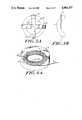
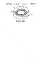
- FIGS. 4A, 4Bshow the coil of FIGS. 2A, 2B in other mounting structures.
- FIGS. 1Ashows a prior art coil construction, wherein an optical fiber 1 is wound about a coilform 2 to form a regular array of circular windings, supported by a central cylindrical support region 3 of the coilform.
- an adhesive 4secures the fibers in position.
- adhesive 4may be replaced by a potting medium, in which case the supporting coilform 2, 3 may be removed after the potting medium has set.
- FIG. 1Bshows a corresponding view of a potted coil from which the coilform has been removed.
- the fiber coilis on or within a mechanically rigid structure, the coilform, the potting medium or both, which can give rise to stresses in the fiber under certain conditions such as differential thermal expansion or contraction as discussed above.
- FIG. 2Ais a view of a fiber coil 10 according to one embodiment of the present invention, wherein a fiber 1 is braided into a wreath to form a self supporting coil of a generally circular form. As illustrated, the coil is of a substantially toroidal or doughnut shape, with each individual winding following a helix around the body of the toroid as it moves progressively along a circumferential path of major diameter "D".
- FIG. 2Bshows a side view of the coil 10 from within the nominal plane of the coil.
- a fiberhas a stiffness or resistance to twisting and bending.
- Applicanthas found that, by exercising reasonable care, a person may hand-wind a coil such as the coil of FIG. 2A without introducing twisting stresses. Accordingly, it will be understood that the winding of the coil illustrated in FIGS. 2A, 2B is effected carefully in order to progressively wind and wrap the fiber about its previously coiled loops, while leaving the fiber in a substantially unstressed position. That is, the twist introduced into the fiber is only the natural rotation of the fiber about its axis corresponding to the helical winding path.
- each successive loopis formed by crossing the fiber a fixed number, e.g., M times, about the body of the coil for each full winding of the fiber around the major diameter D.
- Ma fixed number
- Na spiral twist of M(N-1).
- the ringis held together by the stiffness of the fiber, and resultant friction between the fibers, to form a self-supporting ring structure constituting a well defined optical path for light travelling between the fiber ends la, 1b.
- a coil according to the present inventionis constituted by a first untwisted loop, and a plurality of successive twisted loops which are wound together into a self-orienting coil with no external coilform.
- Such coilmay also be formed with more than one untwisted initial winding, e.g., with a bundle of ten or twenty or more parallel untwisted windings constituting a ring upon which the final turns are wound in a helical winding path as previously described.
- a ring of N loops, having P untwisted parallel windings and (N-P) outer windings each of twist Mproduces a ring of twist (N-P)M.
- Such an embodimentmay be preferred for instruments or environments where it is important to minimize the twist of the fiber.
- the ringis placed on a mounting which orients the ring in a nominal reference plane.
- a mounting 20is shown in FIGS. 3A, 3B. This mounting is a frictional mount, and thus implements principals related to those underlying the coil design.
- the illustrated mounting 20is a cross-shaped structure having arms 21a, 21b, 21c, 21d lying in a nominal plane "P" and defining a planar trellis. After it has been wound, ring 10 is bent to place it onto the trellis in an alternately over-and under manner to frictionally engage each arm. In the illustrated four-arm structure, opposing sides of the ring are symmetrically bent out of the nominal plane to contact the arms. This securely positions the ring in the plane of the trellis, while permitting the ring to slide in that plane along the trellis arms to accommodate circumferential and diametral expansion of the ring. It will be understood that the mounting is not limited to a cross-like structure but may include a trellis with more projecting arms, or a hub and spoke framework with a large number of spokes, or other skeletal structure which frictionally engages the coil.
- the use of such as frictionally engaging mounting structureeffectively decouples the mounting structure from the ring, due to the limited contact area and the the sliding contact between each spoke and the ring. Localized stresses due to differential thermal expansion of the ring and the mounting thus lie below a threshhold determined by the force necessary to overcome friction at the points of contact of the ring and frame.
- the trellis 20is preferably formed of an ultra low expansion glass, such as the "ULE" glass supplied by Hoya.
- the mounting 20 and coil 10are further placed in an isothermal environment to eliminate thermal gradients. This may be accomplished by mounting them within a thermally conductive casing, which is evacuated or is filled with a low conductivity medium.
- a second contemplated mounting structure for the ring 10is a bouyant mounting.
- a mountingis illustrated in FIG. 4A, and includes a closed box or chamber 30 in which the coil 10 is placed.
- Box 30has a shallow cylindrical shape which defines the desired planar orientation of the coil, and is essentially filled with microscopic beads illustrated in part at 32, formed of a material having a density equal to the mean density of the fiber material.
- the coilis uniformly and bouyantly supported without localized frictional or external forces.
- the box dimensioninhibits excessive motion of the fiber, preventing deleterious forces on the fiber ends 1a, 1b, and maintaining the desired planar orientation.
- FIG. 4Bshows another contemplated mounting structure.
- a plurality of filaments 34extend from a frame structure 36 and suspend the ring 10 in a defined plane.
- the filamentswhich may, for example, be carbon or the like, are oriented to cross the fiber windings at an angle, e.g., a right angle, so that they contact the fibers of the ring at a small number of isolated points.
- This suspensiontransmits little heat or stress to the ring, and allows deformation of the ring to accomodate changes in fiber tension.
- the inventionfurther contemplates a hybrid mounting structure incorporating the features of the trellis mounting 20 and the box mounting 30.
- a hybrid structurenot illustrated, the ring 10 is placed on a trellis mount 20 which is then rigidly supported in a defined orientation in a bead-filled box 30.
- This constructionexhibits more precise control of the ring plane, while retaining the essential bouyant support and the sliding frictional support feature for eliminating differential thermal stress as in the previously described mountings.
- one particular contemplated application of the inventionis the construction of a self-supporting fiber coil, as described above, wherein the fiber is a birefringent fiber and is of a length effective to pass light of one polarity input thereto, while extinguishing light of another polarity.
- a related contemplated applicationis the construction of a polarization-preserving self-supporting ring for a fiber optic ring gyro.
Landscapes
- Physics & Mathematics (AREA)
- General Physics & Mathematics (AREA)
- Optics & Photonics (AREA)
- Light Guides In General And Applications Therefor (AREA)
Abstract
Description
Claims (20)
Priority Applications (1)
| Application Number | Priority Date | Filing Date | Title |
|---|---|---|---|
| US07/237,779US4883337A (en) | 1988-08-29 | 1988-08-29 | Low strain optical fiber coil |
Applications Claiming Priority (1)
| Application Number | Priority Date | Filing Date | Title |
|---|---|---|---|
| US07/237,779US4883337A (en) | 1988-08-29 | 1988-08-29 | Low strain optical fiber coil |
Publications (1)
| Publication Number | Publication Date |
|---|---|
| US4883337Atrue US4883337A (en) | 1989-11-28 |
Family
ID=22895137
Family Applications (1)
| Application Number | Title | Priority Date | Filing Date |
|---|---|---|---|
| US07/237,779Expired - Fee RelatedUS4883337A (en) | 1988-08-29 | 1988-08-29 | Low strain optical fiber coil |
Country Status (1)
| Country | Link |
|---|---|
| US (1) | US4883337A (en) |
Cited By (37)
| Publication number | Priority date | Publication date | Assignee | Title |
|---|---|---|---|---|
| US4957344A (en)* | 1989-04-18 | 1990-09-18 | Hughes Aircraft Company | Optical fiber tape assembly and canister |
| US4979796A (en)* | 1989-12-15 | 1990-12-25 | The Charles Stark Draper Laboratory, Inc. | Thermally controlled optical fiber |
| US5005930A (en)* | 1990-02-23 | 1991-04-09 | Hughes Aircraft Company | Multi-directional payout fiber optic canister |
| US5018826A (en)* | 1988-05-19 | 1991-05-28 | U.S. Philips Corp. | Roll manufactured with a light waveguide conductor |
| US5046674A (en)* | 1988-12-24 | 1991-09-10 | U.S. Philips Corporation | Method of blowing a line into an empty sheath |
| US5179613A (en)* | 1989-11-13 | 1993-01-12 | Minnesota Mining And Manufacturing Company | Self-supporting coil of optical fiber and method of forming the coil |
| US5182785A (en)* | 1991-10-10 | 1993-01-26 | W. L. Gore & Associates, Inc. | High-flex optical fiber coil cable |
| US5212760A (en)* | 1991-05-07 | 1993-05-18 | Specimas S.P.A. | Device by which the end of an optical cable incorporated in a power cable unwindable from a drum is maintained fixed relative to an optical reader |
| US5220632A (en)* | 1992-06-24 | 1993-06-15 | Hughes Aircraft Company | Preparation of an optical fiber canister |
| WO1995017693A1 (en)* | 1993-12-22 | 1995-06-29 | Smiths Industries Aerospace & Defense Systems, Inc. | Optical fiber coil and method of winding |
| US5475774A (en)* | 1991-11-25 | 1995-12-12 | Honeywell Inc. | Optical fiber sensor coil using reverse quadrupoles and method of winding same |
| US5500909A (en)* | 1993-02-17 | 1996-03-19 | Abb Research Ltd. | Sensor head for a fiber-optic current measuring device |
| US5545892A (en)* | 1994-09-01 | 1996-08-13 | Litton Systems, Inc. | Gyro sensor coil with low-friction hub interface |
| US5755850A (en)* | 1992-09-24 | 1998-05-26 | Iowa State University Research Foundation | Method of making a surgical laser fiber from a monolithic silica titania glass rod |
| US5767509A (en)* | 1996-12-24 | 1998-06-16 | Litton Systems, Inc. | Fiber optic sensor coil including buffer regions |
| US5818590A (en)* | 1993-09-03 | 1998-10-06 | Litton Systems, Inc. | Flange-supported sensor coil for a fiber optic gyroscope |
| US5841932A (en)* | 1996-06-21 | 1998-11-24 | Honeywell Inc. | Optical fiber coil and method of winding |
| US5868734A (en)* | 1995-11-29 | 1999-02-09 | Iowa State University Research Foundation, Inc. | Methods of using silica-titania clad fibers |
| US6005665A (en)* | 1998-12-29 | 1999-12-21 | Honeywell, Inc. | Job zone for a high performance navigation grade rate sensing coil |
| US6014713A (en)* | 1991-06-10 | 2000-01-11 | International Business Machines Corporation | Computer with retractable optical fiber connector assembly having rotatable spool with optical fiber for connecting the computer to external component |
| WO2003026996A1 (en)* | 2001-09-21 | 2003-04-03 | Corning Incorporated | Apparatus and method for holding coilable elongated product |
| US6608954B2 (en)* | 2000-01-31 | 2003-08-19 | Sumitomo Electric Industries, Ltd. | Optical fiber coil and manufacturing method thereof |
| US20080292261A1 (en)* | 2007-05-07 | 2008-11-27 | Kowalczyk Scott C | Fiber optic enclosure with external cable spool |
| US20090074370A1 (en)* | 2007-08-06 | 2009-03-19 | Adc Telecommunications, Inc. | Fiber optic enclosure with internal cable spool |
| US7869682B2 (en) | 2007-09-05 | 2011-01-11 | Adc Telecommunications, Inc. | Fiber optic enclosure with tear-away spool |
| US20110044599A1 (en)* | 2009-07-21 | 2011-02-24 | Adc Telecommunications, Inc. | Rapid universal rack mount enclosure |
| US8265447B2 (en) | 2008-09-16 | 2012-09-11 | Adc Telecommunications, Inc. | Modular fiber optic enclosure with external cable spool |
| WO2014032033A3 (en)* | 2012-08-23 | 2014-04-24 | Lockheed Martin Corporation | Method and phase-change gain-fiber holder that control temperature rise and uniformity with minimal stress |
| US8837940B2 (en) | 2010-04-14 | 2014-09-16 | Adc Telecommunications, Inc. | Methods and systems for distributing fiber optic telecommunication services to local areas and for supporting distributed antenna systems |
| USRE45153E1 (en) | 2007-01-13 | 2014-09-23 | Adc Telecommunications, Inc. | Fiber optic cable distribution box |
| US9188760B2 (en) | 2011-12-22 | 2015-11-17 | Adc Telecommunications, Inc. | Mini rapid delivery spool |
| US9261663B2 (en) | 2010-06-18 | 2016-02-16 | Adc Communications (Shanghai) Co., Ltd. | Fiber optic distribution terminal and method of deploying fiber distribution cable |
| US9995898B2 (en) | 2010-06-23 | 2018-06-12 | Commscope Technologies Llc | Telecommunications assembly |
| CN108168576A (en)* | 2017-12-15 | 2018-06-15 | 中国船舶重工集团公司第七0七研究所 | One kind is used for the symmetrical coiling method of optical fibre gyro ring tail optical fiber |
| US10371914B2 (en) | 2011-06-24 | 2019-08-06 | Commscope Technologies Llc | Fiber termination enclosure with modular plate assemblies |
| US10545305B2 (en) | 2012-12-19 | 2020-01-28 | CommScope Connectivity Belgium BVBA | Distribution device with incrementally added splitters |
| US11575228B2 (en) | 2020-07-27 | 2023-02-07 | Raytheon Company | Helical strain relief for electrical conductors, fiber optic cables, or other cables |
Citations (8)
| Publication number | Priority date | Publication date | Assignee | Title |
|---|---|---|---|---|
| US4163911A (en)* | 1975-01-27 | 1979-08-07 | Sutter Hospitals Medical Research Foundation | Permanent magnet translational motor for respirators |
| US4408378A (en)* | 1980-11-21 | 1983-10-11 | Associated Electrical Industries Limited | Apparatus for forming a filament coil of figure of eight conformation |
| US4699451A (en)* | 1983-09-10 | 1987-10-13 | International Standard Electric Corp. | Optical fiber coil having juxtaposed ends in same or adjacent layers for rotation rate measuring instrument |
| US4743115A (en)* | 1985-06-21 | 1988-05-10 | Thomson-Csf | Method of coiling an optical fiber gyroscope and an optical fiber coil thus obtained |
| US4768856A (en)* | 1986-01-29 | 1988-09-06 | Standard Elektrik Lorenz A.G. | Optical-waveguide coil and method of making same |
| US4781461A (en)* | 1985-09-21 | 1988-11-01 | Teldix Gmbh | Rpm measuring device utilizing an optical fiber coil and winding method for making the coil |
| US4793708A (en)* | 1987-03-27 | 1988-12-27 | Litton Systems Canada Limited | Fiber optic sensing coil |
| US4802731A (en)* | 1986-10-24 | 1989-02-07 | Bbc Brown Boveri Ag | Optical waveguide arrangement for a high-voltage insulator |
- 1988
- 1988-08-29USUS07/237,779patent/US4883337A/ennot_activeExpired - Fee Related
Patent Citations (8)
| Publication number | Priority date | Publication date | Assignee | Title |
|---|---|---|---|---|
| US4163911A (en)* | 1975-01-27 | 1979-08-07 | Sutter Hospitals Medical Research Foundation | Permanent magnet translational motor for respirators |
| US4408378A (en)* | 1980-11-21 | 1983-10-11 | Associated Electrical Industries Limited | Apparatus for forming a filament coil of figure of eight conformation |
| US4699451A (en)* | 1983-09-10 | 1987-10-13 | International Standard Electric Corp. | Optical fiber coil having juxtaposed ends in same or adjacent layers for rotation rate measuring instrument |
| US4743115A (en)* | 1985-06-21 | 1988-05-10 | Thomson-Csf | Method of coiling an optical fiber gyroscope and an optical fiber coil thus obtained |
| US4781461A (en)* | 1985-09-21 | 1988-11-01 | Teldix Gmbh | Rpm measuring device utilizing an optical fiber coil and winding method for making the coil |
| US4768856A (en)* | 1986-01-29 | 1988-09-06 | Standard Elektrik Lorenz A.G. | Optical-waveguide coil and method of making same |
| US4802731A (en)* | 1986-10-24 | 1989-02-07 | Bbc Brown Boveri Ag | Optical waveguide arrangement for a high-voltage insulator |
| US4793708A (en)* | 1987-03-27 | 1988-12-27 | Litton Systems Canada Limited | Fiber optic sensing coil |
Cited By (103)
| Publication number | Priority date | Publication date | Assignee | Title |
|---|---|---|---|---|
| US5018826A (en)* | 1988-05-19 | 1991-05-28 | U.S. Philips Corp. | Roll manufactured with a light waveguide conductor |
| US5046674A (en)* | 1988-12-24 | 1991-09-10 | U.S. Philips Corporation | Method of blowing a line into an empty sheath |
| US4957344A (en)* | 1989-04-18 | 1990-09-18 | Hughes Aircraft Company | Optical fiber tape assembly and canister |
| US5179613A (en)* | 1989-11-13 | 1993-01-12 | Minnesota Mining And Manufacturing Company | Self-supporting coil of optical fiber and method of forming the coil |
| US4979796A (en)* | 1989-12-15 | 1990-12-25 | The Charles Stark Draper Laboratory, Inc. | Thermally controlled optical fiber |
| US5005930A (en)* | 1990-02-23 | 1991-04-09 | Hughes Aircraft Company | Multi-directional payout fiber optic canister |
| US5212760A (en)* | 1991-05-07 | 1993-05-18 | Specimas S.P.A. | Device by which the end of an optical cable incorporated in a power cable unwindable from a drum is maintained fixed relative to an optical reader |
| US6014713A (en)* | 1991-06-10 | 2000-01-11 | International Business Machines Corporation | Computer with retractable optical fiber connector assembly having rotatable spool with optical fiber for connecting the computer to external component |
| US5182785A (en)* | 1991-10-10 | 1993-01-26 | W. L. Gore & Associates, Inc. | High-flex optical fiber coil cable |
| US5475774A (en)* | 1991-11-25 | 1995-12-12 | Honeywell Inc. | Optical fiber sensor coil using reverse quadrupoles and method of winding same |
| US5220632A (en)* | 1992-06-24 | 1993-06-15 | Hughes Aircraft Company | Preparation of an optical fiber canister |
| US5755850A (en)* | 1992-09-24 | 1998-05-26 | Iowa State University Research Foundation | Method of making a surgical laser fiber from a monolithic silica titania glass rod |
| US5829445A (en)* | 1992-09-24 | 1998-11-03 | Iowa State University Research Foundation, Inc. | Methods for laser treatment of tissue |
| US5500909A (en)* | 1993-02-17 | 1996-03-19 | Abb Research Ltd. | Sensor head for a fiber-optic current measuring device |
| US5818590A (en)* | 1993-09-03 | 1998-10-06 | Litton Systems, Inc. | Flange-supported sensor coil for a fiber optic gyroscope |
| WO1995017693A1 (en)* | 1993-12-22 | 1995-06-29 | Smiths Industries Aerospace & Defense Systems, Inc. | Optical fiber coil and method of winding |
| US5917983A (en)* | 1993-12-22 | 1999-06-29 | Page; Jerry L. | Optical fiber coil and method of winding |
| US5545892A (en)* | 1994-09-01 | 1996-08-13 | Litton Systems, Inc. | Gyro sensor coil with low-friction hub interface |
| US5868734A (en)* | 1995-11-29 | 1999-02-09 | Iowa State University Research Foundation, Inc. | Methods of using silica-titania clad fibers |
| US5841932A (en)* | 1996-06-21 | 1998-11-24 | Honeywell Inc. | Optical fiber coil and method of winding |
| US5767509A (en)* | 1996-12-24 | 1998-06-16 | Litton Systems, Inc. | Fiber optic sensor coil including buffer regions |
| US6005665A (en)* | 1998-12-29 | 1999-12-21 | Honeywell, Inc. | Job zone for a high performance navigation grade rate sensing coil |
| US6608954B2 (en)* | 2000-01-31 | 2003-08-19 | Sumitomo Electric Industries, Ltd. | Optical fiber coil and manufacturing method thereof |
| WO2003026996A1 (en)* | 2001-09-21 | 2003-04-03 | Corning Incorporated | Apparatus and method for holding coilable elongated product |
| USRE45153E1 (en) | 2007-01-13 | 2014-09-23 | Adc Telecommunications, Inc. | Fiber optic cable distribution box |
| USRE46255E1 (en) | 2007-01-13 | 2016-12-27 | Commscope Technologies Llc | Fiber optic cable distribution box |
| USRE48063E1 (en) | 2007-01-13 | 2020-06-23 | Commscope Technologies Llc | Fiber optic cable distribution box |
| USRE49385E1 (en) | 2007-01-13 | 2023-01-24 | Commscope Technologies Llc | Fiber optic cable distribution box |
| US11009671B2 (en) | 2007-05-07 | 2021-05-18 | Commscope Technologies Llc | Fiber optic assembly with cable storage arrangement |
| US20100247051A1 (en)* | 2007-05-07 | 2010-09-30 | Adc Telecommuncations, Inc. | Fiber optic enclosure with external cable spool |
| US10788642B2 (en) | 2007-05-07 | 2020-09-29 | Commscope Technologies Llc | Fiber optic assembly with cable storage arrangement |
| US7715679B2 (en)* | 2007-05-07 | 2010-05-11 | Adc Telecommunications, Inc. | Fiber optic enclosure with external cable spool |
| US10627592B2 (en) | 2007-05-07 | 2020-04-21 | Commscope Technologies Llc | Fiber optic assembly with cable spool |
| US12235506B2 (en) | 2007-05-07 | 2025-02-25 | Commscope Technologies Llc | Fiber optic enclosure with external cable spool |
| US8131126B2 (en) | 2007-05-07 | 2012-03-06 | Adc Telecommunications, Inc. | Fiber optic enclosure with external cable spool |
| US9535227B2 (en) | 2007-05-07 | 2017-01-03 | Commscope Technologies Llc | Fiber optic cable spool assembly |
| US20080292261A1 (en)* | 2007-05-07 | 2008-11-27 | Kowalczyk Scott C | Fiber optic enclosure with external cable spool |
| US9057860B2 (en) | 2007-05-07 | 2015-06-16 | Adc Telecommunications, Inc. | Fiber optic enclosure with external cable spool |
| US8380035B2 (en) | 2007-05-07 | 2013-02-19 | Adc Telecommunications, Inc. | Fiber optic enclosure with external cable spool |
| US10606017B2 (en) | 2007-08-06 | 2020-03-31 | Commscope Technologies Llc | Fiber optic payout assembly including cable spool |
| US10247897B2 (en) | 2007-08-06 | 2019-04-02 | Commscope Technologies Llc | Fiber optic enclosure with internal cable spool |
| US8494333B2 (en) | 2007-08-06 | 2013-07-23 | Adc Telecommunications, Inc. | Dispensing cable from an internal cable spool of a fiber optic enclosure |
| US8705929B2 (en) | 2007-08-06 | 2014-04-22 | Adc Telecommunications, Inc. | Fiber optic enclosure with internal cable spool |
| US7894701B2 (en) | 2007-08-06 | 2011-02-22 | Adc Telecommunications, Inc. | Fiber optic enclosure with internal cable spool |
| US20110158599A1 (en)* | 2007-08-06 | 2011-06-30 | Adc Telecommunications, Inc. | Fiber optic enclosure with internal cable spool |
| US10606015B2 (en) | 2007-08-06 | 2020-03-31 | Commscope Technologies Llc | Fiber optic payout assembly including cable spool |
| US12253734B2 (en) | 2007-08-06 | 2025-03-18 | Commscope Technologies Llc | Fiber optic enclosure with internal cable spool |
| US10895705B2 (en) | 2007-08-06 | 2021-01-19 | Commscope Technologies Llc | Fiber optic enclosure with internal cable spool |
| US8891931B2 (en) | 2007-08-06 | 2014-11-18 | Adc Telecommunications, Inc. | Fiber optic enclosure with internal cable spool |
| US10495836B2 (en) | 2007-08-06 | 2019-12-03 | Commscope Technologies Llc | Fiber optic payout assembly including cable spool |
| US20090074370A1 (en)* | 2007-08-06 | 2009-03-19 | Adc Telecommunications, Inc. | Fiber optic enclosure with internal cable spool |
| US10996418B2 (en) | 2007-08-06 | 2021-05-04 | Commscope Technologies Llc | Connecting subscribers to a fiber optic network using a cable spool |
| US12019301B2 (en) | 2007-08-06 | 2024-06-25 | Commscope Technologies Llc | Fiber optic enclosure with internal cable spool |
| US9261666B2 (en) | 2007-08-06 | 2016-02-16 | Commscope Technologies Llc | Fiber optic enclosure with internal cable spool |
| US10996417B2 (en) | 2007-08-06 | 2021-05-04 | Commscope Technologies Llc | Fiber optic enclosure with internal cable spool and movable cover |
| US10712518B2 (en) | 2007-08-06 | 2020-07-14 | Commscope Technologies Llc | Fiber optic enclosure with lockable internal cable spool |
| US10234648B2 (en) | 2007-08-06 | 2019-03-19 | Commscope Technologies Llc | Fiber optic enclosure with internal cable spool |
| US20100310224A1 (en)* | 2007-08-06 | 2010-12-09 | Adc Telecommunications, Inc. | Fiber optic enclosure with internal cable spool |
| US8189984B2 (en) | 2007-08-06 | 2012-05-29 | Adc Telecommunications, Inc. | Fiber optic enclosure with internal cable spool |
| US7756379B2 (en) | 2007-08-06 | 2010-07-13 | Adc Telecommunications, Inc. | Fiber optic enclosure with internal cable spool |
| US11573390B2 (en) | 2007-08-06 | 2023-02-07 | Commscope Technologies Llc | Fiber optic enclosure with internal cable spool |
| US9606319B2 (en) | 2007-08-06 | 2017-03-28 | Commscope Technologies Llc | Fiber optic enclosure with internal cable spool |
| US8494334B2 (en) | 2007-09-05 | 2013-07-23 | Adc Telecommunications, Inc. | Fiber optic enclosure with tear-away spool |
| US9563032B2 (en) | 2007-09-05 | 2017-02-07 | Commscope Technologies Llc | Fiber optic enclosure with tear-away spool |
| US8774588B2 (en) | 2007-09-05 | 2014-07-08 | Adc Telecommunications, Inc. | Fiber optic enclosure with tear-away spool |
| US8229267B2 (en) | 2007-09-05 | 2012-07-24 | Adc Telecommunications, Inc. | Fiber optic enclosure with tear-away spool |
| US7869682B2 (en) | 2007-09-05 | 2011-01-11 | Adc Telecommunications, Inc. | Fiber optic enclosure with tear-away spool |
| US9229185B2 (en) | 2007-09-05 | 2016-01-05 | Commscope Technologies Llc | Fiber optic enclosure with tear-away spool |
| US8265447B2 (en) | 2008-09-16 | 2012-09-11 | Adc Telecommunications, Inc. | Modular fiber optic enclosure with external cable spool |
| US9448377B2 (en) | 2009-07-21 | 2016-09-20 | Commscope Technologies Llc | Rapid universal rack mount enclosure |
| US9885846B2 (en) | 2009-07-21 | 2018-02-06 | Commscope Technologies Llc | Rapid universal rack mount enclosure |
| US8422847B2 (en) | 2009-07-21 | 2013-04-16 | Adc Telecommunications, Inc. | Rapid universal rack mount enclosure |
| US11809008B2 (en) | 2009-07-21 | 2023-11-07 | Commscope Technologies Llc | Rapid universal rack mount enclosure |
| US8798429B2 (en) | 2009-07-21 | 2014-08-05 | Adc Telecommunications, Inc. | Rapid universal rack mount enclosure |
| US11287592B2 (en) | 2009-07-21 | 2022-03-29 | Commscope Technologies Llc | Rapid universal rack mount enclosure |
| US10768386B2 (en) | 2009-07-21 | 2020-09-08 | Commscope Technologies Llc | Rapid universal rack mount enclosure |
| US20110044599A1 (en)* | 2009-07-21 | 2011-02-24 | Adc Telecommunications, Inc. | Rapid universal rack mount enclosure |
| US12265274B2 (en) | 2009-07-21 | 2025-04-01 | Commscope Technologies Llc | Rapid universal rack mount enclosure |
| US9414137B2 (en) | 2010-04-14 | 2016-08-09 | Commscope Technologies Llc | Methods and systems for distributing fiber optic telecommunication services to local areas and for supporting distributed antenna systems |
| US8837940B2 (en) | 2010-04-14 | 2014-09-16 | Adc Telecommunications, Inc. | Methods and systems for distributing fiber optic telecommunication services to local areas and for supporting distributed antenna systems |
| US10819444B2 (en) | 2010-04-14 | 2020-10-27 | Commscope Technologies Llc | Methods and systems for distributing fiber optic telecommunication services to local areas and for supporting distributed antenna systems |
| US9261663B2 (en) | 2010-06-18 | 2016-02-16 | Adc Communications (Shanghai) Co., Ltd. | Fiber optic distribution terminal and method of deploying fiber distribution cable |
| US9563031B2 (en) | 2010-06-18 | 2017-02-07 | Adc Telecommunications (Shanghai) Distribution Co., Ltd. | Fiber optic enclosure with internal cable spool |
| US9995898B2 (en) | 2010-06-23 | 2018-06-12 | Commscope Technologies Llc | Telecommunications assembly |
| US10884211B2 (en) | 2010-06-23 | 2021-01-05 | Commscope Technologies Llc | Telecommunications assembly |
| US12235504B2 (en) | 2010-06-23 | 2025-02-25 | Commscope Technologies Llc | Telecommunications assembly |
| US10627593B2 (en) | 2010-06-23 | 2020-04-21 | Commscope Technologies Llc | Telecommunications assembly |
| US10268014B2 (en) | 2010-06-23 | 2019-04-23 | Commscope Technologies Llc | Telecommunications assembly |
| US10126516B1 (en) | 2010-06-23 | 2018-11-13 | Commscope Technologies Llc | Telecommunications assembly |
| US11789226B2 (en) | 2010-06-23 | 2023-10-17 | Commscope Technologies Llc | Telecommunications assembly |
| US11402595B2 (en) | 2010-06-23 | 2022-08-02 | Commscope Technologies Llc | Telecommunications assembly |
| US10371914B2 (en) | 2011-06-24 | 2019-08-06 | Commscope Technologies Llc | Fiber termination enclosure with modular plate assemblies |
| US11327262B2 (en) | 2011-06-24 | 2022-05-10 | Commscope Technologies Llc | Fiber termination enclosure with modular plate assemblies |
| US11624884B2 (en) | 2011-06-24 | 2023-04-11 | Commscope Technologies Llc | Fiber termination enclosure with modular plate assemblies |
| US11988883B2 (en) | 2011-06-24 | 2024-05-21 | Commscope Technologies Llc | Fiber termination enclosure with modular plate assemblies |
| US10935744B2 (en) | 2011-06-24 | 2021-03-02 | Commscope Technologies Llc | Fiber termination enclosure with modular plate assemblies |
| US10502916B2 (en) | 2011-06-24 | 2019-12-10 | Commscope Technologies Llc | Fiber termination enclosure with modular plate assemblies |
| US9523834B2 (en) | 2011-12-22 | 2016-12-20 | Commscope Technologies Llc | Fiber optic enclosure |
| US9188760B2 (en) | 2011-12-22 | 2015-11-17 | Adc Telecommunications, Inc. | Mini rapid delivery spool |
| WO2014032033A3 (en)* | 2012-08-23 | 2014-04-24 | Lockheed Martin Corporation | Method and phase-change gain-fiber holder that control temperature rise and uniformity with minimal stress |
| US10545305B2 (en) | 2012-12-19 | 2020-01-28 | CommScope Connectivity Belgium BVBA | Distribution device with incrementally added splitters |
| CN108168576A (en)* | 2017-12-15 | 2018-06-15 | 中国船舶重工集团公司第七0七研究所 | One kind is used for the symmetrical coiling method of optical fibre gyro ring tail optical fiber |
| US11575228B2 (en) | 2020-07-27 | 2023-02-07 | Raytheon Company | Helical strain relief for electrical conductors, fiber optic cables, or other cables |
Similar Documents
| Publication | Publication Date | Title |
|---|---|---|
| US4883337A (en) | Low strain optical fiber coil | |
| Bronnikov et al. | Durable shape sensor based on FBG array inscribed in polyimide-coated multicore optical fiber | |
| US4389090A (en) | Fiber optic polarization controller | |
| US5371593A (en) | Sensor coil for low bias fiber optic gyroscope | |
| TW460718B (en) | Ring photonic crystal fibers | |
| US9248615B2 (en) | Compact fiber optic sensors | |
| EP0488255B1 (en) | Fiber-optic coil and method of manufacturing same | |
| EP0851213B1 (en) | Fiber optic sensor coil including buffer regions | |
| GB2299666A (en) | Coil for a fiber-optic gyroscope | |
| KR100482865B1 (en) | Gyro sensor coil with optical fiber with internal foreskin and injection material | |
| US5444534A (en) | Coil mounting arrangement for fiber optic gyroscope | |
| Wei et al. | Support-free thermally insensitive hollow core fiber coil | |
| US7042572B2 (en) | Fiber optic sensing coil with isotropic properties | |
| Ding et al. | Hollow core fiber temperature sensitivity reduction via winding on a thermally-insensitive coil | |
| US5742390A (en) | Potted gyro sensor coil with inter-turn stress relief | |
| US5767970A (en) | Bonded fiber optic gyro sensor coil including voids | |
| EP1222440B1 (en) | Fiber optic gyroscope | |
| EP0860686B1 (en) | Fiber optic gyro sensor coil with improved temperature stability | |
| Romaniuk et al. | Mosaic optical fibers | |
| JPH10133074A (en) | Overhead optical fiber cable | |
| Alam et al. | Small form-factor PANDA-type HiBi fiber for sensing applications | |
| Ruffin et al. | Fiber winding approaches for environmentally robust IFOG sensor coils | |
| JP2708370B2 (en) | Pot-shaped optical fiber gyro sensor coil | |
| US6141474A (en) | Reinforcement of fiber optic gyroscope coils | |
| WO1989011109A1 (en) | Circularly birefringent optical fibre |
Legal Events
| Date | Code | Title | Description |
|---|---|---|---|
| AS | Assignment | Owner name:CHARLES STARK DRAPER LABORATORY, INC. THE, 555 TEC Free format text:ASSIGNMENT OF ASSIGNORS INTEREST.;ASSIGNOR:DAHLGREN, ROBERT P.;REEL/FRAME:004929/0449 Effective date:19880812 Owner name:CHARLES STARK DRAPER LABORATORY, INC. THE, A CORP Free format text:ASSIGNMENT OF ASSIGNORS INTEREST;ASSIGNOR:DAHLGREN, ROBERT P.;REEL/FRAME:004929/0449 Effective date:19880812 | |
| CC | Certificate of correction | ||
| FEPP | Fee payment procedure | Free format text:PAYOR NUMBER ASSIGNED (ORIGINAL EVENT CODE: ASPN); ENTITY STATUS OF PATENT OWNER: SMALL ENTITY Free format text:PAT HLDR NO LONGER CLAIMS SMALL ENT STAT AS NONPROFIT ORG (ORIGINAL EVENT CODE: LSM3); ENTITY STATUS OF PATENT OWNER: SMALL ENTITY | |
| FEPP | Fee payment procedure | Free format text:PAT HOLDER CLAIMS SMALL ENTITY STATUS - SMALL BUSINESS (ORIGINAL EVENT CODE: SM02); ENTITY STATUS OF PATENT OWNER: SMALL ENTITY | |
| FPAY | Fee payment | Year of fee payment:4 | |
| REMI | Maintenance fee reminder mailed | ||
| LAPS | Lapse for failure to pay maintenance fees | ||
| FP | Lapsed due to failure to pay maintenance fee | Effective date:19971203 | |
| STCH | Information on status: patent discontinuation | Free format text:PATENT EXPIRED DUE TO NONPAYMENT OF MAINTENANCE FEES UNDER 37 CFR 1.362 |