US4882897A - Clutch control structure for a walking operator type lawn mower - Google Patents
Clutch control structure for a walking operator type lawn mowerDownload PDFInfo
- Publication number
- US4882897A US4882897AUS07/274,116US27411688AUS4882897AUS 4882897 AUS4882897 AUS 4882897AUS 27411688 AUS27411688 AUS 27411688AUS 4882897 AUS4882897 AUS 4882897A
- Authority
- US
- United States
- Prior art keywords
- clutch
- control device
- interlocking member
- cutting blade
- clutch lever
- Prior art date
- Legal status (The legal status is an assumption and is not a legal conclusion. Google has not performed a legal analysis and makes no representation as to the accuracy of the status listed.)
- Expired - Fee Related
Links
Images


Classifications
- A—HUMAN NECESSITIES
- A01—AGRICULTURE; FORESTRY; ANIMAL HUSBANDRY; HUNTING; TRAPPING; FISHING
- A01D—HARVESTING; MOWING
- A01D34/00—Mowers; Mowing apparatus of harvesters
- A01D34/01—Mowers; Mowing apparatus of harvesters characterised by features relating to the type of cutting apparatus
- A01D34/412—Mowers; Mowing apparatus of harvesters characterised by features relating to the type of cutting apparatus having rotating cutters
- A01D34/63—Mowers; Mowing apparatus of harvesters characterised by features relating to the type of cutting apparatus having rotating cutters having cutters rotating about a vertical axis
- A01D34/67—Mowers; Mowing apparatus of harvesters characterised by features relating to the type of cutting apparatus having rotating cutters having cutters rotating about a vertical axis hand-guided by a walking operator
- A01D34/68—Mowers; Mowing apparatus of harvesters characterised by features relating to the type of cutting apparatus having rotating cutters having cutters rotating about a vertical axis hand-guided by a walking operator with motor driven cutters or wheels
- A01D34/6806—Driving mechanisms
- A—HUMAN NECESSITIES
- A01—AGRICULTURE; FORESTRY; ANIMAL HUSBANDRY; HUNTING; TRAPPING; FISHING
- A01D—HARVESTING; MOWING
- A01D34/00—Mowers; Mowing apparatus of harvesters
- A01D34/01—Mowers; Mowing apparatus of harvesters characterised by features relating to the type of cutting apparatus
- A01D34/412—Mowers; Mowing apparatus of harvesters characterised by features relating to the type of cutting apparatus having rotating cutters
- A01D34/63—Mowers; Mowing apparatus of harvesters characterised by features relating to the type of cutting apparatus having rotating cutters having cutters rotating about a vertical axis
- A01D34/67—Mowers; Mowing apparatus of harvesters characterised by features relating to the type of cutting apparatus having rotating cutters having cutters rotating about a vertical axis hand-guided by a walking operator
- A01D34/68—Mowers; Mowing apparatus of harvesters characterised by features relating to the type of cutting apparatus having rotating cutters having cutters rotating about a vertical axis hand-guided by a walking operator with motor driven cutters or wheels
- A01D2034/6843—Control levers on the handle of the mower
- A—HUMAN NECESSITIES
- A01—AGRICULTURE; FORESTRY; ANIMAL HUSBANDRY; HUNTING; TRAPPING; FISHING
- A01D—HARVESTING; MOWING
- A01D2101/00—Lawn-mowers
Definitions
- the present inventionrelates to a clutch control structure for a walking operator type lawn mower having a cutting blade clutch.
- a known clutch control structure with a safety measureis disclosed in Japanese Utility Model Publication No. 60-33785, for example, in which the cutting blade is driven only after a manual operation of a clutch lever from a declutching position to a clutch engaging position and another manual operation different from this clutch lever operation. More particularly, a lock mechanism is provided for locking the clutch lever in the declutching position, which lock mechanism is urged to the locking position, and a manual control device is provided for operating the lock mechanism out of the locking position. When the cutting blade clutch is disengaged, the clutch lever is automatically locked in the declutching position. The cutting blade clutch is engaged by releasing the lever lock and switching the clutch lever.
- a primary object of the present inventionis to provide a simple clutch control structure for a walking operator type lawn mower incorporating a safety measure and capable of avoiding damage due to an operational error.
- a clutch control structure for a walking operator type lawn mowercomprises a cutting blade clutch for making and breaking drive transmission to a cutting blade, a steering handle including a grip portion, a clutch lever pivotable between a first position and a second position, a control device operatively connected to the cutting blade clutch and pivotable between a first corresponding position corresponding to the first position for engaging the cutting blade clutch and a second corresponding position corresponding to the second position for disengaging the cutting blade clutch, the control device being constantly urged to the second corresponding position for disengaging the cutting blade clutch, and an interlocking member manually switchable between a release position for breaking an engagement between the control device and the clutch lever to allow the control device and the clutch lever to be operable independently of each other, and an operative position for establishing the engagement between the control device and the clutch lever to allow the control device and the clutch lever to be operable together, the interlocking member being constantly urged to the release position, wherein the cutting blade clutch is engaged by maintaining the interlocking member
- the interlocking memberremains in the release position unless a manual operating force is applied thereto.
- the cutting blade clutchis engaged only when the interlocking member is switched to the operative position and the clutch lever is moved to the first position.
- the clutch leverWhen the clutch lever is switched without switching the interlocking member, the clutch lever alone moves without effect since the clutch lever is not interlocked with the control device. Thus the cutting blade clutch is not engageable at this time.
- the cutting blade clutchis engaged only with two manual operations, i.e. the operation to switch the clutch lever and the operation of the interlocking member. This feature provides the safety measure noted hereinbefore.
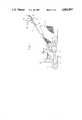
- FIG. 1is a side elevation of the lawn mower
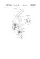
- FIGS. 2 and 3are side views of a clutch lever mounting section, respectively.
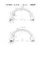
- FIG. 4is a rear view of an interlocking mechanism
- FIG. 5is a sectional view of a clutch device
- FIG. 6is a rear view of a clutch lever
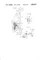
- FIGS. 7 and 8are side views of a clutch lever mounting section of a further embodiment, respectively.
- FIG. 9is a rear view of an interlocking mechanism of the further embodiment.
- FIG. 10is a sectional view of a control device of the further embodiment
- FIG. 11is a perspective view of the control device and a support arm of the further embodiment.
- FIG. 12is a rear view of a clutch lever of the further embodiment.
- a self-propelled, walking operator type lawn mowercomprises front wheels 1, rear wheels 2, a cutting blade 3 mounted for rotation on a vertical axis in a blade housing 4, and an engine E mounted above the blade housing 4 for driving the rear wheels 2 and the cutting blade 3.
- a steering handle 5 and a grass catcher 6extend rearwardly of the blade housing 4.
- a clutch control device 8is connected through a release wire 7 to a cutting blade clutch C mounted in the blade housing 4 for making and breaking drive transmission from the engine E to the cutting blade 3.
- the clutch control device 8is attached to the steering handle 5 through a clutch lever 9, which is shaped as shown in FIG. 6, a lever pivot pin 10 and a lever mounting bracket 11, to be pivotable relative to the steering handle 5 about a pivotal axis P1 of the clutch lever 9.
- the cutting blade clutch Cbecomes disengaged under a self-restoring force when the control device 8 moves to a down position DN as a second corresponding position with a proximal end 8a thereof contacting an undersurface of the lever mounting bracket 11.
- the clutch lever 9carries at an end thereof an interlocking member 14 formed of a rod material, through a support arm 12 urged to pivot with the clutch lever 9.
- the interlocking member 14is provided for releasably interlocking the clutch lever 9 and the control device 8.
- the interlocking member 14is slidable parallel to the axis P1 to switch between an operative position with a tip end thereof inserted into an engagement bore 8b of the control device 8 as shown in a phantom line in FIG. 4 whereby the control device 8 and the support arm 12 are pivotable together, and a release position with the tip end thereof disengaged from the control device 8 as shown in a solid line whereby the control device 8 and the support arm 12 are pivotable relative to each other.
- a control lever 15is formed integral with the interlocking member 14 for effecting the switching operation.
- the control lever 15includes a connection 15a connected to the clutch lever 9, and a spring 16 acts on the connection 15a to urge the interlocking member 14 to the release position.
- the tip end of the interlocking member 14is aligned with the engagement bore 8b only when the clutch lever 9 and the control device 8 are in such a relative position that a free end of the support arm 12 is in contact with a stopper 8c defined on the control device 8 as shown in FIG. 5.
- the self-restoring force of the cutting blade clutch Cplaces the control device 8 in the down position DN, and the clutch lever 9 is movable to a declutching position OFF as a second position as shown in FIG.
- the clutch lever 9may be interlocked with the control device 8 by manually sliding the control lever 15 from a non-interlocking position OUT away from a vertical rod portion 9 a of the clutch lever 9 to an interlocking position IN adjacent the vertical rod portion 9a to switch the interlocking member 14 from the release position to the operative position.
- the clutch lever 9is pivotable about the axis P1 into a clutch engaging position ON as a first position as shown in FIG. 3, with a free intermediate portion thereof located adjacent a grip portion 5a of the steering handle 5 for the operator to grip the clutch lever 9 and the steering handle 5 together.
- control device 8is moved to an up position UP as a first corresponding position to engage the cutting blade clutch C.
- a slight relative pivoting movementoccurs at this time between the control device 8 and the support arm 12 due to the self-restoring force of the cutting blade clutch C, the manual force applied to the clutch lever 9, and the engagement bore 8b having a size slightly greater than the diameter of interlocking member 14.
- the interlocking member 14is maintained in the operative position in spite of the force of spring 16 without a manual force since the interlocking member 14 includes a retaining projection 14a engaging the control device 8 as a result of the relative pivotal movement between the control device 8 and the support arm 12.
- the cutting blade clutch Cis not engaged simply by switching the clutch lever 9 to the clutch engaging position ON.
- the cutting blade clutch Cis engaged to drive the cutting blade 3 only when the control lever 15 is operated to switch the interlocking member 14 to the operative position and the clutch lever 9 is switched to the clutch engaging position ON.
- a mowing operationis carried out with the cutting blade clutch C engaged while the operator grips the steering handle 5 and the clutch lever 9 in the clutch engaging position ON.
- a control lever 17 in FIGS. 2 and 3is provided for operating a propelling clutch not shown.
- FIGS. 7 through 12Another embodiment is shown in FIGS. 7 through 12, which is different from the foregoing embodiment in the following respect:
- This embodimentincludes an interlocking member 14 and an interlocking control lever 15 pivotable about an axis P2 perpendicular to the pivotal axis P1 of the clutch lever 9 to switch between an operative position to engage the control device 8 and a release position disengaged from the control device 8, or attached to the clutch lever 9 to be switchable between an interlocking position IN adjacent the vertical rod portion 9a of the clutch lever 9 and a non-interlocking position OUT away from the vertical rod portion 9a.
- the interlocking mechanism between the control device 8 and the clutch lever 9may be constructed such that the interlocking member is maintained in the operative position by gripping the interlocking control lever with the clutch lever.
Landscapes
- Life Sciences & Earth Sciences (AREA)
- Environmental Sciences (AREA)
- Harvester Elements (AREA)
Abstract
Description
The present invention relates to a clutch control structure for a walking operator type lawn mower having a cutting blade clutch.
A known clutch control structure with a safety measure is disclosed in Japanese Utility Model Publication No. 60-33785, for example, in which the cutting blade is driven only after a manual operation of a clutch lever from a declutching position to a clutch engaging position and another manual operation different from this clutch lever operation. More particularly, a lock mechanism is provided for locking the clutch lever in the declutching position, which lock mechanism is urged to the locking position, and a manual control device is provided for operating the lock mechanism out of the locking position. When the cutting blade clutch is disengaged, the clutch lever is automatically locked in the declutching position. The cutting blade clutch is engaged by releasing the lever lock and switching the clutch lever.
In the known control structure, however, the operator may apply an undue operating force to the clutch lever, forgetting to release the lever lock. The operating force thus applied tends to result in deformation or damage of the clutch lever or of the locking mechanism acting as a safety device.
A primary object of the present invention is to provide a simple clutch control structure for a walking operator type lawn mower incorporating a safety measure and capable of avoiding damage due to an operational error.
In order to achieve this object, a clutch control structure for a walking operator type lawn mower according to the present invention comprises a cutting blade clutch for making and breaking drive transmission to a cutting blade, a steering handle including a grip portion, a clutch lever pivotable between a first position and a second position, a control device operatively connected to the cutting blade clutch and pivotable between a first corresponding position corresponding to the first position for engaging the cutting blade clutch and a second corresponding position corresponding to the second position for disengaging the cutting blade clutch, the control device being constantly urged to the second corresponding position for disengaging the cutting blade clutch, and an interlocking member manually switchable between a release position for breaking an engagement between the control device and the clutch lever to allow the control device and the clutch lever to be operable independently of each other, and an operative position for establishing the engagement between the control device and the clutch lever to allow the control device and the clutch lever to be operable together, the interlocking member being constantly urged to the release position, wherein the cutting blade clutch is engaged by maintaining the interlocking member in the operative position and moving the clutch lever to the first position.
In the above construction, the interlocking member remains in the release position unless a manual operating force is applied thereto. The cutting blade clutch is engaged only when the interlocking member is switched to the operative position and the clutch lever is moved to the first position. When the clutch lever is switched without switching the interlocking member, the clutch lever alone moves without effect since the clutch lever is not interlocked with the control device. Thus the cutting blade clutch is not engageable at this time.
Because of the mounting and urging construction for the interlocking member, the cutting blade clutch is engaged only with two manual operations, i.e. the operation to switch the clutch lever and the operation of the interlocking member. This feature provides the safety measure noted hereinbefore.
When the clutch lever alone is operated, the clutch lever makes a lost motion absorbing the operational force. Consequently, an operational error in operating the clutch lever alone hardly results in deformation or damage. The clutch control structure of the present invention is thus trouble-free and reliable.
Other objects, features and advantages of the present invention will be apparent from the following description.
The drawings show clutch control structures for a walking operator type lawn mower according to the present invention, in which:
FIG. 1 is a side elevation of the lawn mower,
FIGS. 2 and 3 are side views of a clutch lever mounting section, respectively,
FIG. 4 is a rear view of an interlocking mechanism,
FIG. 5 is a sectional view of a clutch device,
FIG. 6 is a rear view of a clutch lever,
FIGS. 7 and 8 are side views of a clutch lever mounting section of a further embodiment, respectively,
FIG. 9 is a rear view of an interlocking mechanism of the further embodiment,
FIG. 10 is a sectional view of a control device of the further embodiment,
FIG. 11 is a perspective view of the control device and a support arm of the further embodiment, and
FIG. 12 is a rear view of a clutch lever of the further embodiment.
Referring to FIG. 1, a self-propelled, walking operator type lawn mower comprises front wheels 1,rear wheels 2, acutting blade 3 mounted for rotation on a vertical axis in a blade housing 4, and an engine E mounted above the blade housing 4 for driving therear wheels 2 and thecutting blade 3. Asteering handle 5 and agrass catcher 6 extend rearwardly of the blade housing 4.
Referring to FIGS. 2 through 4, aclutch control device 8 is connected through arelease wire 7 to a cutting blade clutch C mounted in the blade housing 4 for making and breaking drive transmission from the engine E to thecutting blade 3. Theclutch control device 8 is attached to thesteering handle 5 through aclutch lever 9, which is shaped as shown in FIG. 6, alever pivot pin 10 and alever mounting bracket 11, to be pivotable relative to thesteering handle 5 about a pivotal axis P1 of theclutch lever 9. The cutting blade clutch C becomes disengaged under a self-restoring force when thecontrol device 8 moves to a down position DN as a second corresponding position with aproximal end 8a thereof contacting an undersurface of thelever mounting bracket 11.
Theclutch lever 9 carries at an end thereof an interlockingmember 14 formed of a rod material, through asupport arm 12 urged to pivot with theclutch lever 9. The interlockingmember 14 is provided for releasably interlocking theclutch lever 9 and thecontrol device 8. The interlockingmember 14 is slidable parallel to the axis P1 to switch between an operative position with a tip end thereof inserted into an engagement bore 8b of thecontrol device 8 as shown in a phantom line in FIG. 4 whereby thecontrol device 8 and thesupport arm 12 are pivotable together, and a release position with the tip end thereof disengaged from thecontrol device 8 as shown in a solid line whereby thecontrol device 8 and thesupport arm 12 are pivotable relative to each other. Acontrol lever 15 is formed integral with the interlockingmember 14 for effecting the switching operation. Thecontrol lever 15 includes aconnection 15a connected to theclutch lever 9, and aspring 16 acts on theconnection 15a to urge the interlockingmember 14 to the release position. The tip end of the interlockingmember 14 is aligned with the engagement bore 8b only when theclutch lever 9 and thecontrol device 8 are in such a relative position that a free end of thesupport arm 12 is in contact with astopper 8c defined on thecontrol device 8 as shown in FIG. 5. The self-restoring force of the cutting blade clutch C places thecontrol device 8 in the down position DN, and theclutch lever 9 is movable to a declutching position OFF as a second position as shown in FIG. 2, which is the above-mentioned position relative to thecontrol device 8 in the down position DN. Only in this position theclutch lever 9 may be interlocked with thecontrol device 8 by manually sliding thecontrol lever 15 from a non-interlocking position OUT away from avertical rod portion 9 a of theclutch lever 9 to an interlocking position IN adjacent thevertical rod portion 9a to switch the interlockingmember 14 from the release position to the operative position. In this position theclutch lever 9 is pivotable about the axis P1 into a clutch engaging position ON as a first position as shown in FIG. 3, with a free intermediate portion thereof located adjacent agrip portion 5a of thesteering handle 5 for the operator to grip theclutch lever 9 and thesteering handle 5 together. As a result, thecontrol device 8 is moved to an up position UP as a first corresponding position to engage the cutting blade clutch C. A slight relative pivoting movement occurs at this time between thecontrol device 8 and thesupport arm 12 due to the self-restoring force of the cutting blade clutch C, the manual force applied to theclutch lever 9, and the engagement bore 8b having a size slightly greater than the diameter of interlockingmember 14. The interlockingmember 14 is maintained in the operative position in spite of the force ofspring 16 without a manual force since the interlockingmember 14 includes aretaining projection 14a engaging thecontrol device 8 as a result of the relative pivotal movement between thecontrol device 8 and thesupport arm 12. When the operator releases theclutch lever 9 in the clutch engaging position ON, the self-restoring force of the cutting blade clutch C automatically returns theclutch lever 9 to the declutching position OFF and thecontrol device 8 to the down position DN. At the same time the interlockingmember 14 is automatically switched to the release position under the force ofspring 16.
Thus, the cutting blade clutch C is not engaged simply by switching theclutch lever 9 to the clutch engaging position ON. The cutting blade clutch C is engaged to drive thecutting blade 3 only when thecontrol lever 15 is operated to switch the interlockingmember 14 to the operative position and theclutch lever 9 is switched to the clutch engaging position ON. A mowing operation is carried out with the cutting blade clutch C engaged while the operator grips thesteering handle 5 and theclutch lever 9 in the clutch engaging position ON.
Acontrol lever 17 in FIGS. 2 and 3 is provided for operating a propelling clutch not shown.
Another embodiment is shown in FIGS. 7 through 12, which is different from the foregoing embodiment in the following respect:
This embodiment includes an interlockingmember 14 and aninterlocking control lever 15 pivotable about an axis P2 perpendicular to the pivotal axis P1 of theclutch lever 9 to switch between an operative position to engage thecontrol device 8 and a release position disengaged from thecontrol device 8, or attached to theclutch lever 9 to be switchable between an interlocking position IN adjacent thevertical rod portion 9a of theclutch lever 9 and a non-interlocking position OUT away from thevertical rod portion 9a.
The interlocking mechanism between thecontrol device 8 and theclutch lever 9 may be constructed such that the interlocking member is maintained in the operative position by gripping the interlocking control lever with the clutch lever.
Claims (10)
1. A clutch control structure for a walking operator type lawn mower comprising
a cutting blade clutch (C) for making and breaking drive transmission to a cutting blade (3),
a steering handle (5) including a grip portion (5a),
a clutch lever (9) pivotable between a first position and a second position,
a control device (8) operatively connected to said cutting blade clutch (C) and pivotable between a first corresponding position corresponding to said first position for engaging said cutting blade clutch (C) and a second corresponding position corresponding to said second position for disengaging said cutting blade clutch (C), said control device (8) being constantly urged to said second corresponding position for disengaging said cutting blade clutch (C), and
an interlocking member (14) manually switchable between a release position for breaking an engagement between said control device (8) and said clutch lever (9) to allow said control device (8) and said clutch lever (9) to be operable independently of each other, and an operative position for establishing the engagement between said control device (8) and said clutch lever (9) to allow said control device (8) and said clutch lever (9) to be operable together, said interlocking member (14) being constantly urged to said release position,
wherein said cutting blade clutch (C) is engaged by maintaining said interlocking member (14) in said operative position and moving said clutch lever (9) to said first position.
2. A clutch control structure as claimed in claim 1, wherein said first position of said clutch lever (9) is an upper position adjacent said grip portion (5a) and said second position is a lower position away from said grip portion (5a), said clutch lever (9) being manually pivotable between said first position and said second position about an axis (P1) provided by said steering handle (5), and said control device (8) is pivotable between said first corresponding position and said second corresponding position about said axis (P1).
3. A clutch control structure as claimed in claim 2, wherein said interlocking member (14) is pivotable between said operative position and said release position about an axis (P2) perpendicular to said axis (P1).
4. A clutch control structure as claimed in claim 2, wherein said interlocking member (14) is slidable parallel to said axis (P1) between said operative position and said release position.
5. A clutch control structure as claimed in claim 1, wherein said interlocking member (14) is urged by a spring to said release position.
6. A clutch control structure as claimed in claim 1, wherein said interlocking member (14) is switchable between said operative position and said release position by movement thereof into and out of an engagement bore (8b) defined in said control device (8).
7. A clutch control structure as claimed in claim 6, wherein said control device (8) includes a stopper (8c) for setting a positional relationship between said control device (8) and an arm (12) attached to said clutch lever (9) when said interlocking member (14) is moved into said engagement bore (8b).
8. A clutch control structure as claimed in claim 6, wherein said interlocking member (14) includes a retaining projection (14a) for preventing said interlocking member (14) from becoming disengaged from said engagement bore (8b) of said control device (8) when said interlocking member (14) is in said operative position and said clutch lever (9) is in said first position.
9. A clutch control structure as claimed in claim 1, wherein said interlocking member (14) is integrally provided with an interlocking control device (15), said interlocking member (14) being operable by a manual control of said interlocking control device (15).
10. A clutch control structure as claimed in claim 8, wherein said interlocking control device (15) extends along part of said clutch lever (9).
Applications Claiming Priority (4)
| Application Number | Priority Date | Filing Date | Title |
|---|---|---|---|
| JP30116887AJPH01142817A (en) | 1987-11-28 | 1987-11-28 | Clutch operation structure for walking type lawn mower |
| JP62-301168 | 1987-11-28 | ||
| JP30431887AJPH01144108A (en) | 1987-11-30 | 1987-11-30 | Clutch operating structure for walk type mowing machine |
| JP62-304318 | 1987-11-30 |
Publications (1)
| Publication Number | Publication Date |
|---|---|
| US4882897Atrue US4882897A (en) | 1989-11-28 |
Family
ID=26562582
Family Applications (1)
| Application Number | Title | Priority Date | Filing Date |
|---|---|---|---|
| US07/274,116Expired - Fee RelatedUS4882897A (en) | 1987-11-28 | 1988-11-21 | Clutch control structure for a walking operator type lawn mower |
Country Status (1)
| Country | Link |
|---|---|
| US (1) | US4882897A (en) |
Cited By (25)
| Publication number | Priority date | Publication date | Assignee | Title |
|---|---|---|---|---|
| EP0496164A1 (en)* | 1990-12-21 | 1992-07-29 | Briggs & Stratton Corporation | Lawnmower handle assembly |
| US5195307A (en)* | 1992-01-21 | 1993-03-23 | The Toro Company | Simplified blade brake clutch and propulsion control |
| US5261214A (en)* | 1992-08-21 | 1993-11-16 | The Toro Company | Lawn mower bail pivot stop and cable anchor |
| US5367861A (en)* | 1991-12-17 | 1994-11-29 | Kubota Corporation | Riding lawn mower |
| EP0410819B1 (en)* | 1989-07-28 | 1995-02-15 | Honda Giken Kogyo Kabushiki Kaisha | Hydraulic transmission for motor vehicles |
| EP0791288A1 (en)* | 1996-02-22 | 1997-08-27 | Honda Giken Kogyo Kabushiki Kaisha | Operating lever device for power-driven work machine |
| WO1999021407A1 (en)* | 1997-10-29 | 1999-05-06 | Kamm Michael A | Lawn mower bail |
| EP1211168A1 (en)* | 2000-11-29 | 2002-06-05 | Julius Tielbürger GmbH & Co. KG | Landscape maintenance apparatus |
| US6658829B2 (en)* | 2001-08-22 | 2003-12-09 | Honda Giken Kogyo Kabushiki Kaisha | Electric lawn mower |
| US20040093767A1 (en)* | 2002-11-14 | 2004-05-20 | Phillip Thomas E. | Split wireform bail |
| US20050144919A1 (en)* | 2004-01-05 | 2005-07-07 | Honda Motor Co., Ltd. | Variable speed transmission twist-grip throttle control apparatuses and methods for self-propelled mowing machine |
| US20050257964A1 (en)* | 2004-05-21 | 2005-11-24 | Derby Harry L V | Method of operator presence control on walk behind powered equipment |
| US20060101613A1 (en)* | 2004-11-17 | 2006-05-18 | Nilfisk-Advance, Inc. | Control handle assembly |
| US20060218887A1 (en)* | 2004-06-17 | 2006-10-05 | Honda Motor Co., Ltd. | Apparatuses and methods for controlling self-propelled machines |
| US20070256401A1 (en)* | 2006-04-27 | 2007-11-08 | Yoshihisa Hibi | Drive operation device of walk-behind lawn mower |
| US20090107095A1 (en)* | 2007-10-26 | 2009-04-30 | Scott Kaskawitz | Variable speed transmission adjustable twist control apparatuses and methods for self-propelled mowing machine |
| US20090127009A1 (en)* | 2007-11-21 | 2009-05-21 | Honda Motor Co., Ltd. | Handle structure of walk-behind working machine |
| US20120297921A1 (en)* | 2009-12-17 | 2012-11-29 | Yukihiko Gondou | Cutting blade clutch for mower |
| US11246262B2 (en) | 2012-10-15 | 2022-02-15 | Chervon (Hk) Limited | Operation safety assembly for a lawncare apparatus |
| US20220338412A1 (en)* | 2019-05-10 | 2022-10-27 | Kaaz Corporation | Electric work machine with cutting blade |
| US11558999B2 (en) | 2019-11-21 | 2023-01-24 | Globe (Jiangsu) Co., Ltd | Garden tool and control method thereof |
| US11606900B2 (en) | 2012-10-15 | 2023-03-21 | Chervon (Hk) Limited | Gardening tool |
| US11638397B2 (en) | 2020-02-10 | 2023-05-02 | Techtronic Cordless Gp | Control assembly coupled to handle of an implement |
| US20240246216A1 (en)* | 2018-05-23 | 2024-07-25 | Milwaukee Electric Tool Corporation | Powerhead unit for tool |
| US12108702B2 (en) | 2012-10-15 | 2024-10-08 | Chervon (Hk) Limited | Gardening tool, particularly a mower |
Citations (6)
| Publication number | Priority date | Publication date | Assignee | Title |
|---|---|---|---|---|
| US4433530A (en)* | 1982-09-23 | 1984-02-28 | Simplicity Manufacturing, Inc. | Interlock mechanism preventing engine starting when a mower is in power drive |
| US4538401A (en)* | 1982-10-20 | 1985-09-03 | Honda Giken Kogyo Kabushiki Kaisha | Control lever assembly in a self-propelled lawn mower |
| US4721494A (en)* | 1985-09-02 | 1988-01-26 | Kubota, Ltd. | Drive transmission structure for tractor |
| US4747256A (en)* | 1986-02-17 | 1988-05-31 | Kubota, Ltd. | Lever mounting structure for lawn mower |
| US4753062A (en)* | 1987-06-11 | 1988-06-28 | Capro, Inc. | Lawn mower and safety control therefor |
| JPH0633785A (en)* | 1992-07-15 | 1994-02-08 | Isuzu Ceramics:Kenkyusho:Kk | Heat insulating gas engine with valve opening control device |
- 1988
- 1988-11-21USUS07/274,116patent/US4882897A/ennot_activeExpired - Fee Related
Patent Citations (6)
| Publication number | Priority date | Publication date | Assignee | Title |
|---|---|---|---|---|
| US4433530A (en)* | 1982-09-23 | 1984-02-28 | Simplicity Manufacturing, Inc. | Interlock mechanism preventing engine starting when a mower is in power drive |
| US4538401A (en)* | 1982-10-20 | 1985-09-03 | Honda Giken Kogyo Kabushiki Kaisha | Control lever assembly in a self-propelled lawn mower |
| US4721494A (en)* | 1985-09-02 | 1988-01-26 | Kubota, Ltd. | Drive transmission structure for tractor |
| US4747256A (en)* | 1986-02-17 | 1988-05-31 | Kubota, Ltd. | Lever mounting structure for lawn mower |
| US4753062A (en)* | 1987-06-11 | 1988-06-28 | Capro, Inc. | Lawn mower and safety control therefor |
| JPH0633785A (en)* | 1992-07-15 | 1994-02-08 | Isuzu Ceramics:Kenkyusho:Kk | Heat insulating gas engine with valve opening control device |
Cited By (35)
| Publication number | Priority date | Publication date | Assignee | Title |
|---|---|---|---|---|
| EP0410819B1 (en)* | 1989-07-28 | 1995-02-15 | Honda Giken Kogyo Kabushiki Kaisha | Hydraulic transmission for motor vehicles |
| EP0496164A1 (en)* | 1990-12-21 | 1992-07-29 | Briggs & Stratton Corporation | Lawnmower handle assembly |
| US5367861A (en)* | 1991-12-17 | 1994-11-29 | Kubota Corporation | Riding lawn mower |
| US5195307A (en)* | 1992-01-21 | 1993-03-23 | The Toro Company | Simplified blade brake clutch and propulsion control |
| US5261214A (en)* | 1992-08-21 | 1993-11-16 | The Toro Company | Lawn mower bail pivot stop and cable anchor |
| EP0791288A1 (en)* | 1996-02-22 | 1997-08-27 | Honda Giken Kogyo Kabushiki Kaisha | Operating lever device for power-driven work machine |
| WO1999021407A1 (en)* | 1997-10-29 | 1999-05-06 | Kamm Michael A | Lawn mower bail |
| EP1211168A1 (en)* | 2000-11-29 | 2002-06-05 | Julius Tielbürger GmbH & Co. KG | Landscape maintenance apparatus |
| US6658829B2 (en)* | 2001-08-22 | 2003-12-09 | Honda Giken Kogyo Kabushiki Kaisha | Electric lawn mower |
| US20040093767A1 (en)* | 2002-11-14 | 2004-05-20 | Phillip Thomas E. | Split wireform bail |
| US6745548B1 (en) | 2002-11-14 | 2004-06-08 | Ariens Company | Split wireform bail |
| US20050144919A1 (en)* | 2004-01-05 | 2005-07-07 | Honda Motor Co., Ltd. | Variable speed transmission twist-grip throttle control apparatuses and methods for self-propelled mowing machine |
| US20080047246A1 (en)* | 2004-01-05 | 2008-02-28 | Osborne Christopher M | Variable speed transmission twist-grip throttle control apparatuses and methods for self-propelled mowing machine |
| US20050257964A1 (en)* | 2004-05-21 | 2005-11-24 | Derby Harry L V | Method of operator presence control on walk behind powered equipment |
| US7240756B2 (en)* | 2004-05-21 | 2007-07-10 | Textron Inc. | Method of operator presence control on walk behind powered equipment |
| US20060218887A1 (en)* | 2004-06-17 | 2006-10-05 | Honda Motor Co., Ltd. | Apparatuses and methods for controlling self-propelled machines |
| US7293397B2 (en) | 2004-06-17 | 2007-11-13 | Honda Motor Co., Ltd. | Apparatuses and methods for controlling self-propelled machines |
| US20060101613A1 (en)* | 2004-11-17 | 2006-05-18 | Nilfisk-Advance, Inc. | Control handle assembly |
| US7730577B2 (en) | 2004-11-17 | 2010-06-08 | Nilfisk-Advance, Inc. | Control handle assembly |
| US20070256401A1 (en)* | 2006-04-27 | 2007-11-08 | Yoshihisa Hibi | Drive operation device of walk-behind lawn mower |
| US7543429B2 (en) | 2007-10-26 | 2009-06-09 | Honda Motor Co., Ltd. | Variable speed transmission adjustable twist control apparatuses and methods for self-propelled mowing machine |
| US20090107095A1 (en)* | 2007-10-26 | 2009-04-30 | Scott Kaskawitz | Variable speed transmission adjustable twist control apparatuses and methods for self-propelled mowing machine |
| US20090127009A1 (en)* | 2007-11-21 | 2009-05-21 | Honda Motor Co., Ltd. | Handle structure of walk-behind working machine |
| US7845442B2 (en)* | 2007-11-21 | 2010-12-07 | Honda Motor Co., Ltd. | Handle structure of walk-behind working machine |
| US20120297921A1 (en)* | 2009-12-17 | 2012-11-29 | Yukihiko Gondou | Cutting blade clutch for mower |
| US11252867B2 (en) | 2012-10-15 | 2022-02-22 | Chervon (Hk) Limited | Safety assembly for a lawncare apparatus |
| US11246262B2 (en) | 2012-10-15 | 2022-02-15 | Chervon (Hk) Limited | Operation safety assembly for a lawncare apparatus |
| US11606900B2 (en) | 2012-10-15 | 2023-03-21 | Chervon (Hk) Limited | Gardening tool |
| US12108702B2 (en) | 2012-10-15 | 2024-10-08 | Chervon (Hk) Limited | Gardening tool, particularly a mower |
| US12364192B2 (en) | 2012-10-15 | 2025-07-22 | Chervon (Hk) Limited | Lawncare apparatus |
| US20240246216A1 (en)* | 2018-05-23 | 2024-07-25 | Milwaukee Electric Tool Corporation | Powerhead unit for tool |
| US12318904B2 (en)* | 2018-05-23 | 2025-06-03 | Milwaukee Electric Tool Corporation | Powerhead unit for tool |
| US20220338412A1 (en)* | 2019-05-10 | 2022-10-27 | Kaaz Corporation | Electric work machine with cutting blade |
| US11558999B2 (en) | 2019-11-21 | 2023-01-24 | Globe (Jiangsu) Co., Ltd | Garden tool and control method thereof |
| US11638397B2 (en) | 2020-02-10 | 2023-05-02 | Techtronic Cordless Gp | Control assembly coupled to handle of an implement |
Similar Documents
| Publication | Publication Date | Title |
|---|---|---|
| US4882897A (en) | Clutch control structure for a walking operator type lawn mower | |
| CA1217061A (en) | Control lever assembly in a self-propelled lawn mower | |
| US4413466A (en) | Control assembly for blade clutch unit | |
| JP2550673B2 (en) | Operating device for walking mower | |
| US4281732A (en) | Two-stage deadman control for walk-behind mower | |
| EP2227937B1 (en) | Bail-free machine control devices and methods | |
| US9414539B2 (en) | Door prop in a lawn mower | |
| US4747256A (en) | Lever mounting structure for lawn mower | |
| US4573543A (en) | Double-safety arrangement for a self-propelled hand-guided machine | |
| US4230200A (en) | Two-stage deadman control for walk-behind mowers | |
| US4432191A (en) | Method and apparatus for controlling blade clutch assembly | |
| US4543850A (en) | Neutral lock mechanism for a direction and speed control pedal | |
| US4760687A (en) | Mower deck height and clutch control | |
| US5237888A (en) | Apparatus for remote motion control | |
| US4984479A (en) | Control system for a snow blower traction vehicle | |
| JPH02244310A (en) | Clutch lever support structure of walk type working machine | |
| JP3725223B2 (en) | Emergency stop device for traveling machine | |
| JP4851012B2 (en) | Clutch operating device for work vehicle | |
| JPH01144108A (en) | Clutch operating structure for walk type mowing machine | |
| JPH0524525B2 (en) | ||
| JPH01142817A (en) | Clutch operation structure for walking type lawn mower | |
| JP3404891B2 (en) | Operation lever holding device for walking lawn mower | |
| JPS5940649B2 (en) | Rotary Craftsman | |
| JPH0135943Y2 (en) | ||
| JPH0620384B2 (en) | Clutch operation structure of walking type agricultural machine |
Legal Events
| Date | Code | Title | Description |
|---|---|---|---|
| AS | Assignment | Owner name:KUBOTA, LTD., 47-GO, 2-BAN, 1-CHOME, SHIKITSUHIGAS Free format text:ASSIGNMENT OF ASSIGNORS INTEREST.;ASSIGNORS:OSHIMA, HIROSHI;SADAKANE, HIROFUMI;KATAYAMA, TAKAO;AND OTHERS;REEL/FRAME:004975/0079 Effective date:19881014 Owner name:KUBOTA, LTD., JAPAN Free format text:ASSIGNMENT OF ASSIGNORS INTEREST;ASSIGNORS:OSHIMA, HIROSHI;SADAKANE, HIROFUMI;KATAYAMA, TAKAO;AND OTHERS;REEL/FRAME:004975/0079 Effective date:19881014 | |
| FEPP | Fee payment procedure | Free format text:PAYOR NUMBER ASSIGNED (ORIGINAL EVENT CODE: ASPN); ENTITY STATUS OF PATENT OWNER: LARGE ENTITY | |
| FPAY | Fee payment | Year of fee payment:4 | |
| REMI | Maintenance fee reminder mailed | ||
| LAPS | Lapse for failure to pay maintenance fees | ||
| FP | Lapsed due to failure to pay maintenance fee | Effective date:19971203 | |
| STCH | Information on status: patent discontinuation | Free format text:PATENT EXPIRED DUE TO NONPAYMENT OF MAINTENANCE FEES UNDER 37 CFR 1.362 |