US4882797A - Ophthalmic surgery stretcher - Google Patents
Ophthalmic surgery stretcherDownload PDFInfo
- Publication number
- US4882797A US4882797AUS07/073,677US7367787AUS4882797AUS 4882797 AUS4882797 AUS 4882797AUS 7367787 AUS7367787 AUS 7367787AUS 4882797 AUS4882797 AUS 4882797A
- Authority
- US
- United States
- Prior art keywords
- assembly
- headrest
- stretcher
- support plate
- frame
- Prior art date
- Legal status (The legal status is an assumption and is not a legal conclusion. Google has not performed a legal analysis and makes no representation as to the accuracy of the status listed.)
- Expired - Lifetime
Links
- 238000001356surgical procedureMethods0.000titleabstractdescription7
- 210000000707wristAnatomy0.000claimsabstractdescription30
- 230000000712assemblyEffects0.000description6
- 238000000429assemblyMethods0.000description6
- 229910000831SteelInorganic materials0.000description5
- 239000010959steelSubstances0.000description5
- 210000003127kneeAnatomy0.000description4
- 239000003638chemical reducing agentSubstances0.000description3
- 230000003028elevating effectEffects0.000description2
- 230000003247decreasing effectEffects0.000description1
- 230000002980postoperative effectEffects0.000description1
- 230000001681protective effectEffects0.000description1
- 238000011084recoveryMethods0.000description1
Images


Classifications
- A—HUMAN NECESSITIES
- A61—MEDICAL OR VETERINARY SCIENCE; HYGIENE
- A61G—TRANSPORT, PERSONAL CONVEYANCES, OR ACCOMMODATION SPECIALLY ADAPTED FOR PATIENTS OR DISABLED PERSONS; OPERATING TABLES OR CHAIRS; CHAIRS FOR DENTISTRY; FUNERAL DEVICES
- A61G13/00—Operating tables; Auxiliary appliances therefor
- A61G13/02—Adjustable operating tables; Controls therefor
- A61G13/08—Adjustable operating tables; Controls therefor the table being divided into different adjustable sections
- A—HUMAN NECESSITIES
- A61—MEDICAL OR VETERINARY SCIENCE; HYGIENE
- A61G—TRANSPORT, PERSONAL CONVEYANCES, OR ACCOMMODATION SPECIALLY ADAPTED FOR PATIENTS OR DISABLED PERSONS; OPERATING TABLES OR CHAIRS; CHAIRS FOR DENTISTRY; FUNERAL DEVICES
- A61G1/00—Stretchers
- A61G1/02—Stretchers with wheels
- A61G1/0237—Stretchers with wheels having at least one swivelling wheel, e.g. castors
- A61G1/0243—Stretchers with wheels having at least one swivelling wheel, e.g. castors with lockable swivel action, e.g. fixing castor in certain direction
- A—HUMAN NECESSITIES
- A61—MEDICAL OR VETERINARY SCIENCE; HYGIENE
- A61G—TRANSPORT, PERSONAL CONVEYANCES, OR ACCOMMODATION SPECIALLY ADAPTED FOR PATIENTS OR DISABLED PERSONS; OPERATING TABLES OR CHAIRS; CHAIRS FOR DENTISTRY; FUNERAL DEVICES
- A61G13/00—Operating tables; Auxiliary appliances therefor
- A61G13/10—Parts, details or accessories
- A61G13/12—Rests specially adapted therefor; Arrangements of patient-supporting surfaces
- A—HUMAN NECESSITIES
- A61—MEDICAL OR VETERINARY SCIENCE; HYGIENE
- A61G—TRANSPORT, PERSONAL CONVEYANCES, OR ACCOMMODATION SPECIALLY ADAPTED FOR PATIENTS OR DISABLED PERSONS; OPERATING TABLES OR CHAIRS; CHAIRS FOR DENTISTRY; FUNERAL DEVICES
- A61G7/00—Beds specially adapted for nursing; Devices for lifting patients or disabled persons
- A61G7/05—Parts, details or accessories of beds
- A61G7/0507—Side-rails
- A61G7/0508—Side-rails characterised by a particular connection mechanism
- A61G7/0509—Side-rails characterised by a particular connection mechanism sliding or pivoting downwards
- A—HUMAN NECESSITIES
- A61—MEDICAL OR VETERINARY SCIENCE; HYGIENE
- A61B—DIAGNOSIS; SURGERY; IDENTIFICATION
- A61B90/00—Instruments, implements or accessories specially adapted for surgery or diagnosis and not covered by any of the groups A61B1/00 - A61B50/00, e.g. for luxation treatment or for protecting wound edges
- A61B90/60—Supports for surgeons, e.g. chairs or hand supports
- A—HUMAN NECESSITIES
- A61—MEDICAL OR VETERINARY SCIENCE; HYGIENE
- A61G—TRANSPORT, PERSONAL CONVEYANCES, OR ACCOMMODATION SPECIALLY ADAPTED FOR PATIENTS OR DISABLED PERSONS; OPERATING TABLES OR CHAIRS; CHAIRS FOR DENTISTRY; FUNERAL DEVICES
- A61G13/00—Operating tables; Auxiliary appliances therefor
- A61G13/10—Parts, details or accessories
- A61G13/12—Rests specially adapted therefor; Arrangements of patient-supporting surfaces
- A61G13/1205—Rests specially adapted therefor; Arrangements of patient-supporting surfaces for specific parts of the body
- A61G13/121—Head or neck
- A—HUMAN NECESSITIES
- A61—MEDICAL OR VETERINARY SCIENCE; HYGIENE
- A61G—TRANSPORT, PERSONAL CONVEYANCES, OR ACCOMMODATION SPECIALLY ADAPTED FOR PATIENTS OR DISABLED PERSONS; OPERATING TABLES OR CHAIRS; CHAIRS FOR DENTISTRY; FUNERAL DEVICES
- A61G13/00—Operating tables; Auxiliary appliances therefor
- A61G13/10—Parts, details or accessories
- A61G13/12—Rests specially adapted therefor; Arrangements of patient-supporting surfaces
- A61G13/1205—Rests specially adapted therefor; Arrangements of patient-supporting surfaces for specific parts of the body
- A61G13/1245—Knees, upper or lower legs
Definitions
- the field of the inventionrelates to an ophthalmic surgery stretcher having an articulatable head piece.
- Ophthalmic surgery stretcherstypically include a one-piece, tapered fowler/head section, a wrist rest assembly secured to the head end on both sides of the stretcher frame, and controls for adjusting the angular position of the tapered head with respect to the remainder of the stretcher.
- the fowler/head sectionis usually adjustable from the flat position through ninety degrees through a single adjustment.
- An ophthalmic surgery support assemblypreferably in the form of a stretcher, is provided by the invention.
- the stretcherincludes a frame, a backrest assembly pivotably mounted to the frame, and a headrest assembly of relatively small width pivotably mounted to the front end of the backrest assembly.
- a mounting bracket assemblymay be mounted beneath the support surface of the headrest. This assembly is pivotably mounted to the backrest frame.
- a receiver tubeis mounted to the mounting bracket assembly. The tube extends in the longitudinal direction.
- a wrist rest assembly including an L-shaped supportis mounted to the receiver tube when an operation is to be performed. One end of the L-shaped support fits within the tube and is secured therein by a torque knob or the like.
- the wrist rest assemblymay be replaced by a head extension piece which fits about the head support surface and extends the width thereof to substantially the full width of the stretcher.
- the head extension pieceincludes a mounting assembly which includes a shaft which fits within the receiver tube.
- FIG. 1is a side elevation view of an ophthalmic surgery stretcher in accordance with the invention
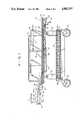
- FIG. 2is a partially cutaway top plan view thereof
- FIG. 3is an enlarged, partially sectional side elevation view of the head portion of the stretcher
- FIG. 4is an enlarged, partially cutaway bottom plan view of the head portion of the stretcher
- FIG. 5is a perspective view of the head portion of stretcher including a head extension piece mounted thereto;
- FIG. 6is a sectional elevation view of the head portion of the stretcher including the head extension piece mounted thereto.
- FIGS. 1-2An ophthalmic surgery stretcher 10 according to the invention is shown in FIGS. 1-2.
- the stretcherincludes a base assembly 12, a top assembly 14, a pair of side rails 16, a knee frame and cover assembly 18, a foot frame and cover assembly 20, a foot frame support assembly 22, and a fowler backrest assembly 24.
- the top assemblyis supported by a pair of hydraulic piston/cylinder assemblies 26 mounted to the base assembly.
- a pair of longitudinal baskets 28are also mounted to the base assembly.
- a pair of elevating screw assemblies including cranks 30,32are provided for elevating the head and foot ends of the stretcher, respectively.
- the formerincludes a relatively long screw nut tube assembly 34 while the latter includes a shorter tube assembly 36.
- These assembliesallow the crank operated fowler backrest assembly 24 and the knee frame assembly 18 to be raised or lowered.
- Both the backrest and knee frame assembliesare mounted to pivotable cross bars 37 and rotate about the respective axes of the bars when the appropriate crank is employed.
- a pair of ratchet plates 38are provided near the foot end of the stretcher for allowing the foot frame and cover assembly 20 to be positioned at a desired height.
- the hydraulic control button assembly 40, wheels 42 including a locking steering caster system, side pedals 44 for adjusting the height of the stretcher, and the components described abovehave been successfully employed in the industry and their operations are well understood by those skilled in the art. They accordingly shall not be described in greater detail herein.
- the inventionconcerns a novel fowler backrest assembly/headrest combination and a wrist rest assembly 46 and headrest extension assembly 48 which may be employed therewith.
- the fowler backrest assembly 24includes a tubular frame 50 made from chrome-plated steel or the like.
- a steel support plate 52is mounted to the frame.
- a pair of parallel, chrome-plated steel tubes 54are welded to the front and rear portions of the frame 50.
- a first substantially rectangular steel plate 56is welded to the opposing tubes 54.
- the plate 56supports a gear box 58 including a worm gear reducer 60.
- a housing 62may be provided for protecting the gear box and associated components.
- a pair of shafts 64extend in opposite directions from the worm gear reducer and are rotatable therewith.
- a lever 66is welded to the end of each shaft. Each lever is pivotably secured to a headrest connecting rod 68.
- a linkage assembly 70 having a worm gear 72 on one end thereof and knob 74 at its opposite endis used for actuating the 50:1 ratio gear box 58.
- the linkage assemblyincludes a plurality of connecting tubes 76, an extension shaft 78, an adjustment rod 80, a plurality of universal joints 82, and a slide shaft 84.
- the connecting tubesare hollow and slotted.
- the shafts extending within these tubeseach include a pin 86 near one end thereof which extends through these slots. Rings 88 are provided near each end of the connecting tubes to insure the pins 86 remain within the slots.
- the length of the linkage assemblymay be increased or decreased as the extension shaft 78, adjustment rod 80 and slide shaft 84 move within the respective, slotted connecting tubes 76.
- the linkage assemblymay also be pivoted about the universal joints 82 as the head and foot ends of the stretcher are raised or lowered.
- Spring pins 90are employed where appropriate to insure the entire linkage assembly rotates about its longitudinal axis when the knob 74 is turned.
- Means(not shown) are provided for supporting the linkage assembly at appropriate locations along the stretcher.
- a head support plate 92is mounted to the fowler backrest assembly 24.
- a pair of loop fastener sections 94are adhered to the surface of the plate 92 for allowing a cushion 96 having corresponding hook fastener sections to be secured thereto.
- the plateis bolted to a bracket 98 which has a cross section resembling an inverted U (see FIG. 6).
- a base plate 100is welded to the bracket 98.
- a second U-shaped bracket assembly 102is mounted to the bottom of the rectangular steel plate 56.
- a rotatable sleeve 104which runs substantially parallel to the cross bars 37, is supported by the bracket assembly 102.
- a main support plate 106is welded at one end to the sleeve 104 and bolted directly beneath the base plate 100.
- a pair of opposing brackets 108are welded to the bottom of the main support plate 106.
- the headrest connecting rods 68are pivotably mounted, respectively, to the opposing brackets. Rotation of the shafts 64 within the gear box 58 causes the levers 66 to rotate about the axis defined by the shaft.
- the connecting rods 68being pivotably secured to the levers 66 and the brackets 108, cause the main support plate 106 to rotate about the longitudinal axis of the sleeve 104 to which it is secured. As shown in FIG. 3, the head support plate 92 is accordingly rotatable with the main support plate 106 to a position about twenty-five degrees above the plane of the fowler backrest assembly to one about forty degrees below it.
- a tube 110 having a substantially square cross sectionis welded to the bottom of the main support plate 106 and extends longitudinally with respect to the stretcher. It is centrally positioned with respect to the sides of the head support plate 92.
- a set screw 112 and associated knob 114are mounted to the square tube 110.
- the wrist rest assembly 46 or the head support extension piece 48may be mounted to the head piece through the use of the tube.
- the wrist rest assemblyincludes a U-shaped wrist support 116, a shaft 118 mounted to the support, a slotted tube 120, and a square tube 122 extending substantially perpendicularly from the slotted tube 120.
- the square tube 122is positioned within the slightly larger tube 110 and locked therein by the set screw 112.
- the height of the wrist supportis adjusted by sliding shaft 118 within the slotted tube 120 and securing it with a torque knob 124.
- the top portion of the wrist rest assemblyis locked rotationally in the slotted support tube 120 by a flat washer 126 between the torque knob and the support tube. The washer, when compressed by the torque knob, is loaded against the two edges of the slot (not shown) defined in the support; tube, thereby eliminating any rotational movement of the wrist rest assembly.
- the headrest extension assemblyprovides the headrest portion of the stretcher with nearly a full fowler width surface area and a full perimeter protective bumper 128. It includes a generally U-shaped plate 130, a pair of loop fastener sections 132 adhered to the plate, and a generally U-shaped cushion 134 mounted to the plate through the use of hook-type fasteners which adhere to the loop fastener sections.
- a mounting bracket 136is secured to the bottom surface of the plate 130 and includes a square tube 138 extending therefrom. This square tube 138 fits within the square tube 110 mounted to plate 106 and is locked therein by the set screw 112.
- a pair of plates 140are riveted to opposing edge portions of the plate 130. Each pair defines a slot which accommodates an edge of the head support plate 92.
- the backrest assembly 24is moved to a desired angular orientation by turning crank 30.
- the knee and foot frame assembliesare likewise positioned by turning crank 32.
- the seat pan 142remains in the same plane as the stretcher frame 144 during these operations.
- the wrist rest assembly 46is mounted to the headrest 146 by inserting tube 122 into tube 110.
- Knob 114is then turned to lock the wrist rest mounting tube 122 in place.
- the height of the wrist rest assemblyis adjusted by loosening knob 124. This allows the column 118 supporting the wrist support 116 to slide within the slotted tube 120. Once the height has been set, the torque knob is turned to lock the column 118 in position.
- the angular orientation of the headrest 146 with respect to the fowler backrest assembly 24is adjusted by turning knob 74. This causes the linkage assembly 70, and thereby the worm gear 72 to rotate.
- the worm gearbeing engaged to a 50:1 reducer within the gear box 58, causes the rotation of shafts 64 and the levers 66 mounted to the shafts.
- the connecting rods 68which are pivotably connected to the levers 66 and the main support plate 106, cause the latter to rotate about the axis of sleeve 104.
- the headrest assembly 146being mounted to the main support plate 106, accordingly moves about the longitudinal axis of sleeve 104. Since the sleeve 104 is mounted to the fowler backrest assembly 24, the angular orientation of the headrest assembly may thereby be adjusted with respect to the backrest assembly.
- the narrow width of the headrest assembly and the convenient location of the wrist rest assembly 46provide easy access to the patient's head.
- the wrist rest assemblyis removed by loosening knob 114 and sliding tube 122 out from tube 110.
- the headrest extension assembly 48is then mounted to the stretcher by inserting tube 138 within tube 110 and insuring that the head support plate 92 is positioned within the opposing slots defined by the mounting plates 140.
- the knob 114is tightened when the cushions 96,134 are in abutting positions.
- the head support plate 92 and extension plate 130will also be substantially coplanar and define a substantially contiguous surface area when the headrest extension is properly mounted. A substantially full width headrest is thereby provided which is extremely useful for post-operative recovery.
Landscapes
- Health & Medical Sciences (AREA)
- Life Sciences & Earth Sciences (AREA)
- Animal Behavior & Ethology (AREA)
- General Health & Medical Sciences (AREA)
- Public Health (AREA)
- Veterinary Medicine (AREA)
- Engineering & Computer Science (AREA)
- Biomedical Technology (AREA)
- Nursing (AREA)
- Accommodation For Nursing Or Treatment Tables (AREA)
Abstract
Description
Claims (20)
Priority Applications (1)
| Application Number | Priority Date | Filing Date | Title |
|---|---|---|---|
| US07/073,677US4882797A (en) | 1987-07-15 | 1987-07-15 | Ophthalmic surgery stretcher |
Applications Claiming Priority (1)
| Application Number | Priority Date | Filing Date | Title |
|---|---|---|---|
| US07/073,677US4882797A (en) | 1987-07-15 | 1987-07-15 | Ophthalmic surgery stretcher |
Publications (1)
| Publication Number | Publication Date |
|---|---|
| US4882797Atrue US4882797A (en) | 1989-11-28 |
Family
ID=22115117
Family Applications (1)
| Application Number | Title | Priority Date | Filing Date |
|---|---|---|---|
| US07/073,677Expired - LifetimeUS4882797A (en) | 1987-07-15 | 1987-07-15 | Ophthalmic surgery stretcher |
Country Status (1)
| Country | Link |
|---|---|
| US (1) | US4882797A (en) |
Cited By (21)
| Publication number | Priority date | Publication date | Assignee | Title |
|---|---|---|---|---|
| US5208928A (en)* | 1991-09-20 | 1993-05-11 | Midmark Corporation | Plastic surgery table |
| US5326128A (en)* | 1991-09-09 | 1994-07-05 | Csn Manufacturing, Inc. | Variable-width torsion spring axle |
| US5335384A (en)* | 1992-11-10 | 1994-08-09 | Hill-Rom Company, Inc. | Hospital bed head extender and accessory therfor |
| US5561878A (en)* | 1994-09-30 | 1996-10-08 | Hill-Rom Company, Inc. | Hospital bed with integral selectively manipulatable support |
| WO1999003418A3 (en)* | 1997-07-14 | 1999-04-08 | Hill Rom Co Inc | Surgical stretcher |
| EP0971614A4 (en)* | 1996-10-23 | 2000-05-17 | Hill Rom Co Inc | Intergrated siderail and accessory rail for a bed |
| US6202230B1 (en) | 1997-11-07 | 2001-03-20 | Hill-Rom, Inc. | Surgical table apparatus |
| EP1123690A3 (en)* | 1996-10-23 | 2002-03-27 | Hill-Rom, Inc. | Procedural stretcher recline controls |
| WO2002028338A2 (en) | 2000-09-29 | 2002-04-11 | Hill-Rom Services, Inc. | Surgery stretcher |
| US6654974B2 (en) | 2000-06-02 | 2003-12-02 | Hill-Rom Services, Inc. | Foot support for a patient support |
| US6739006B2 (en) | 1997-11-07 | 2004-05-25 | Hill-Rom Services, Inc. | Head section support for a surgical table apparatus |
| US6754923B2 (en) | 1997-11-07 | 2004-06-29 | Hill-Rom Services, Inc. | Leg section support for a surgical table |
| US6757924B2 (en) | 1999-08-23 | 2004-07-06 | Hill-Rom Services, Inc. | Bed having a removable foot section |
| US20040141589A1 (en)* | 2003-01-17 | 2004-07-22 | Sharpensteen Charles C. | Pad assembly adapted for receiving an x-ray cassette and method of using the same |
| US20060168727A1 (en)* | 2005-01-31 | 2006-08-03 | Hill-Rom Services, Inc. | Birthing support apparatus |
| US7657953B2 (en) | 2005-11-17 | 2010-02-09 | Hill-Rom Services, Inc. | Birthing bed calf support |
| US20110047705A1 (en)* | 2009-08-27 | 2011-03-03 | Marvin Gorovitz | Massage table with comfort feature |
| US8683629B2 (en)* | 2012-06-28 | 2014-04-01 | Ergomotion, Inc. | Articulating bed with lumbar and head adjustment |
| CN103876903A (en)* | 2014-04-08 | 2014-06-25 | 朱萍 | Operating bed for department of ophthalmology |
| US20150164721A1 (en)* | 2012-08-18 | 2015-06-18 | Tizai Keieisha Co., Ltd. | Sleeping position-controlling bed system |
| US20190191890A1 (en)* | 2017-12-27 | 2019-06-27 | Apex Health Care Mfg. Inc. | Electric Bed with Independent Adjusting Device for Waist Rest |
Citations (12)
| Publication number | Priority date | Publication date | Assignee | Title |
|---|---|---|---|---|
| US1626091A (en)* | 1924-02-07 | 1927-04-26 | Jesse W Macklin | Osteopathic operating table |
| US2042399A (en)* | 1934-06-12 | 1936-05-26 | Edward D Holme Jr | Combined chair and table |
| US3041121A (en)* | 1960-09-26 | 1962-06-26 | Ritter Co Inc | Surgical table |
| SU178046A3 (en)* | 1964-12-25 | 1966-02-24 | ||
| US3411766A (en)* | 1966-02-23 | 1968-11-19 | American Hospital Supply Corp | Operating table |
| US3635461A (en)* | 1969-11-14 | 1972-01-18 | American Sterilizer Co | Surgical table and control |
| US3754749A (en)* | 1971-06-25 | 1973-08-28 | Medical Eng Dev Co | Multi-articulated table |
| US3929309A (en)* | 1974-08-26 | 1975-12-30 | Pierce Louis B | Head rest |
| US4103170A (en)* | 1977-09-22 | 1978-07-25 | Spradlin Richard V | Portable medical table |
| US4247091A (en)* | 1979-02-08 | 1981-01-27 | Borg-Warner Corporation | Adjustable labor-delivery-recovery hospital bed |
| US4390011A (en)* | 1981-05-06 | 1983-06-28 | Evans Daniel R | Adjustable surgical arm rest and instrument platform |
| US4700691A (en)* | 1985-03-18 | 1987-10-20 | Metripond Merleggyar | Head restraining device for operating procedures on the head |
- 1987
- 1987-07-15USUS07/073,677patent/US4882797A/ennot_activeExpired - Lifetime
Patent Citations (12)
| Publication number | Priority date | Publication date | Assignee | Title |
|---|---|---|---|---|
| US1626091A (en)* | 1924-02-07 | 1927-04-26 | Jesse W Macklin | Osteopathic operating table |
| US2042399A (en)* | 1934-06-12 | 1936-05-26 | Edward D Holme Jr | Combined chair and table |
| US3041121A (en)* | 1960-09-26 | 1962-06-26 | Ritter Co Inc | Surgical table |
| SU178046A3 (en)* | 1964-12-25 | 1966-02-24 | ||
| US3411766A (en)* | 1966-02-23 | 1968-11-19 | American Hospital Supply Corp | Operating table |
| US3635461A (en)* | 1969-11-14 | 1972-01-18 | American Sterilizer Co | Surgical table and control |
| US3754749A (en)* | 1971-06-25 | 1973-08-28 | Medical Eng Dev Co | Multi-articulated table |
| US3929309A (en)* | 1974-08-26 | 1975-12-30 | Pierce Louis B | Head rest |
| US4103170A (en)* | 1977-09-22 | 1978-07-25 | Spradlin Richard V | Portable medical table |
| US4247091A (en)* | 1979-02-08 | 1981-01-27 | Borg-Warner Corporation | Adjustable labor-delivery-recovery hospital bed |
| US4390011A (en)* | 1981-05-06 | 1983-06-28 | Evans Daniel R | Adjustable surgical arm rest and instrument platform |
| US4700691A (en)* | 1985-03-18 | 1987-10-20 | Metripond Merleggyar | Head restraining device for operating procedures on the head |
Non-Patent Citations (5)
| Title |
|---|
| Hausted Minor Surgery Stretcher 675 Unicare II, (1985).* |
| O/E 4000 Stretcher/Table (1985), Lada International, Arlington Heights, Il.* |
| Reliance M 701 Stretcher (1985) F and F Koenigkramer, Cincinnati, Oh.* |
| Reliance M-701 Stretcher (1985) F and F Koenigkramer, Cincinnati, Oh. |
| SurgiBed 962 Stretcher.* |
Cited By (51)
| Publication number | Priority date | Publication date | Assignee | Title |
|---|---|---|---|---|
| US5326128A (en)* | 1991-09-09 | 1994-07-05 | Csn Manufacturing, Inc. | Variable-width torsion spring axle |
| US5208928A (en)* | 1991-09-20 | 1993-05-11 | Midmark Corporation | Plastic surgery table |
| US5335384A (en)* | 1992-11-10 | 1994-08-09 | Hill-Rom Company, Inc. | Hospital bed head extender and accessory therfor |
| US5561878A (en)* | 1994-09-30 | 1996-10-08 | Hill-Rom Company, Inc. | Hospital bed with integral selectively manipulatable support |
| EP1123690A3 (en)* | 1996-10-23 | 2002-03-27 | Hill-Rom, Inc. | Procedural stretcher recline controls |
| EP0971614A4 (en)* | 1996-10-23 | 2000-05-17 | Hill Rom Co Inc | Intergrated siderail and accessory rail for a bed |
| US6249923B1 (en) | 1997-07-14 | 2001-06-26 | Hill-Rom, Inc. | Adjustable head rest for a patient support |
| US6314597B2 (en) | 1997-07-14 | 2001-11-13 | Hill-Rom Services, Inc. | Stretcher foot pedal |
| WO1999003418A3 (en)* | 1997-07-14 | 1999-04-08 | Hill Rom Co Inc | Surgical stretcher |
| US6202231B1 (en)* | 1997-07-14 | 2001-03-20 | Hill-Rom, Inc. | Surgical stretcher |
| US6108840A (en)* | 1997-07-14 | 2000-08-29 | Hill-Rom, Inc. | Head rest for a patient support |
| US6076208A (en)* | 1997-07-14 | 2000-06-20 | Hill-Rom, Inc. | Surgical stretcher |
| US6739006B2 (en) | 1997-11-07 | 2004-05-25 | Hill-Rom Services, Inc. | Head section support for a surgical table apparatus |
| US6276012B2 (en) | 1997-11-07 | 2001-08-21 | Hill-Rom Services, Inc. | Surgical table apparatus |
| US6202230B1 (en) | 1997-11-07 | 2001-03-20 | Hill-Rom, Inc. | Surgical table apparatus |
| US6754923B2 (en) | 1997-11-07 | 2004-06-29 | Hill-Rom Services, Inc. | Leg section support for a surgical table |
| US7464421B2 (en) | 1999-08-23 | 2008-12-16 | Hill-Rom Services, Inc. | Bed having a removable foot section |
| US20060236457A1 (en)* | 1999-08-23 | 2006-10-26 | Brent Goodwin | Bed having a removable foot section |
| US7073221B2 (en) | 1999-08-23 | 2006-07-11 | Hill-Rom Services, Inc. | Bed having a removable foot section |
| US6757924B2 (en) | 1999-08-23 | 2004-07-06 | Hill-Rom Services, Inc. | Bed having a removable foot section |
| US6857153B2 (en) | 2000-06-02 | 2005-02-22 | Hill-Rom Services, Inc. | Patient support having a light assembly |
| US6854145B2 (en) | 2000-06-02 | 2005-02-15 | Hill-Rom Services, Inc. | Patient support |
| US6654974B2 (en) | 2000-06-02 | 2003-12-02 | Hill-Rom Services, Inc. | Foot support for a patient support |
| US7469433B2 (en) | 2000-06-02 | 2008-12-30 | Hill-Rom Services, Inc. | Patient support with variable length actuator and release mechanism for lowering a sectional support surface |
| US6718580B2 (en) | 2000-09-29 | 2004-04-13 | Hill-Rom Services, Inc. | Stretcher having pivotable and lockable patient support sections |
| US6681426B2 (en) | 2000-09-29 | 2004-01-27 | Hill-Rom Services, Inc. | Mattress for surgery stretcher |
| US6578215B1 (en) | 2000-09-29 | 2003-06-17 | Hill-Rom Services, Inc. | Surgery stretcher |
| WO2002028338A3 (en)* | 2000-09-29 | 2002-06-06 | Hill Rom Services Inc | Surgery stretcher |
| WO2002028338A2 (en) | 2000-09-29 | 2002-04-11 | Hill-Rom Services, Inc. | Surgery stretcher |
| US20040141589A1 (en)* | 2003-01-17 | 2004-07-22 | Sharpensteen Charles C. | Pad assembly adapted for receiving an x-ray cassette and method of using the same |
| US6893156B2 (en) | 2003-01-17 | 2005-05-17 | Steris Inc. | Pad assembly adapted for receiving an x-ray cassette and method of using the same |
| US20060168727A1 (en)* | 2005-01-31 | 2006-08-03 | Hill-Rom Services, Inc. | Birthing support apparatus |
| US7536734B2 (en) | 2005-01-31 | 2009-05-26 | Hill-Rom Services, Inc. | Birthing support apparatus |
| US7676868B2 (en) | 2005-11-17 | 2010-03-16 | Hill-Rom Services, Inc. | Birthing bed foot support release handle |
| US8640287B2 (en) | 2005-11-17 | 2014-02-04 | Hill-Rom Services, Inc. | Patient-support apparatus with a locking deck section |
| US7657953B2 (en) | 2005-11-17 | 2010-02-09 | Hill-Rom Services, Inc. | Birthing bed calf support |
| US7757317B2 (en) | 2005-11-17 | 2010-07-20 | Hill-Rom Services, Inc. | Stowing birthing bed foot section |
| US7669259B2 (en) | 2005-11-17 | 2010-03-02 | Hill-Rom Services, Inc. | Stowing birthing bed foot section |
| US8079101B2 (en) | 2005-11-17 | 2011-12-20 | Hill-Rom Services, Inc. | Over-molded limb support |
| US8117697B2 (en) | 2005-11-17 | 2012-02-21 | Hill-Rom Services, Inc. | Patient-support apparatus with a locking deck section |
| US8327480B2 (en) | 2005-11-17 | 2012-12-11 | Hill-Rom Services, Inc. | Birthing bed lift off foot section |
| US8555437B2 (en)* | 2009-08-27 | 2013-10-15 | Marvin Gorovitz | Massage table with comfort feature |
| US20110047705A1 (en)* | 2009-08-27 | 2011-03-03 | Marvin Gorovitz | Massage table with comfort feature |
| US8683629B2 (en)* | 2012-06-28 | 2014-04-01 | Ergomotion, Inc. | Articulating bed with lumbar and head adjustment |
| US20150164721A1 (en)* | 2012-08-18 | 2015-06-18 | Tizai Keieisha Co., Ltd. | Sleeping position-controlling bed system |
| US9757295B2 (en)* | 2012-08-18 | 2017-09-12 | Tizai Keieisha Co., Ltd | Sleeping position-controlling bed system |
| US9907716B2 (en) | 2012-08-18 | 2018-03-06 | Tizai Keieisha Co., Ltd | Sleeping position-controlling bed system |
| CN103876903A (en)* | 2014-04-08 | 2014-06-25 | 朱萍 | Operating bed for department of ophthalmology |
| CN103876903B (en)* | 2014-04-08 | 2015-12-30 | 蒋巧玲 | A kind of ophthalmic operating table |
| US20190191890A1 (en)* | 2017-12-27 | 2019-06-27 | Apex Health Care Mfg. Inc. | Electric Bed with Independent Adjusting Device for Waist Rest |
| US10786087B2 (en)* | 2017-12-27 | 2020-09-29 | Apex Health Care Mfg. Inc. | Electric bed with independent adjusting device for waist rest |
Similar Documents
| Publication | Publication Date | Title |
|---|---|---|
| US4882797A (en) | Ophthalmic surgery stretcher | |
| US4097939A (en) | Hospital bed | |
| US4966379A (en) | Reclinable wheelchair | |
| US11369538B2 (en) | Reconfigurable pelvic support for a surgical frame and method for use thereof | |
| US4660549A (en) | Adjustable head support for chiropractic table | |
| US10888484B2 (en) | Reconfigurable pelvic support for surgical frame and method for use thereof | |
| US5480212A (en) | Medical instrument positioner and patient support apparatus | |
| US4958817A (en) | Operating table | |
| US5862549A (en) | Maternity bed | |
| CA1098436A (en) | Obstetric chair | |
| US3972081A (en) | Bed arrangement | |
| EP0501712B1 (en) | Surgery table | |
| US5208928A (en) | Plastic surgery table | |
| US4730842A (en) | Adjustable wheelchair | |
| US5926878A (en) | Maternity bed | |
| US4071916A (en) | Apparatus for rocking a bed | |
| DE69413735T2 (en) | Adjustable backrest for a chair | |
| US4848833A (en) | Tablet arm assembly | |
| US4648654A (en) | Adjustable vehicle seat | |
| US12403058B2 (en) | Reconfigurable upper leg support for a surgical frame | |
| US7367623B2 (en) | Ergonomic chair | |
| GB2100979A (en) | Equipment for handling invalids and the disabled | |
| US4451082A (en) | Seat for a baby's push chair | |
| US6436126B1 (en) | Head flexion mechanism for chiropractic table | |
| US4732141A (en) | Chiropractic table with swingable section |
Legal Events
| Date | Code | Title | Description |
|---|---|---|---|
| AS | Assignment | Owner name:HAUSTED, INC., 927 LAKE ROAD, MEDINA, OHIO A CORP. Free format text:ASSIGNMENT OF ASSIGNORS INTEREST.;ASSIGNORS:FAILOR, RAYMOND A.;PETERS, GERALD;REUTER, MARK;REEL/FRAME:004848/0697 Effective date:19880301 Owner name:HAUSTED, INC.,OHIO Free format text:ASSIGNMENT OF ASSIGNORS INTEREST;ASSIGNORS:FAILOR, RAYMOND A.;PETERS, GERALD;REUTER, MARK;REEL/FRAME:004848/0697 Effective date:19880301 | |
| STCF | Information on status: patent grant | Free format text:PATENTED CASE | |
| FPAY | Fee payment | Year of fee payment:4 | |
| AS | Assignment | Owner name:JACKSON NATIONAL LIFE INSURANCE COMPANY, MICHIGAN Free format text:SECURITY INTEREST;ASSIGNOR:HAUSTED, INC., A DELAWARE CORPORATION;REEL/FRAME:006741/0258 Effective date:19931007 | |
| AS | Assignment | Owner name:JACKSON NATIONAL LIFE INSURANCE COMPANY, AS HOLDER Free format text:ASSIGNMENT OF ASSIGNORS INTEREST;ASSIGNOR:HAUSTED, INC.;REEL/FRAME:006740/0630 Effective date:19931007 | |
| REMI | Maintenance fee reminder mailed | ||
| FPAY | Fee payment | Year of fee payment:8 | |
| SULP | Surcharge for late payment | ||
| FEPP | Fee payment procedure | Free format text:PAYOR NUMBER ASSIGNED (ORIGINAL EVENT CODE: ASPN); ENTITY STATUS OF PATENT OWNER: SMALL ENTITY | |
| FEPP | Fee payment procedure | Free format text:PAYOR NUMBER ASSIGNED (ORIGINAL EVENT CODE: ASPN); ENTITY STATUS OF PATENT OWNER: SMALL ENTITY | |
| FEPP | Fee payment procedure | Free format text:PAYER NUMBER DE-ASSIGNED (ORIGINAL EVENT CODE: RMPN); ENTITY STATUS OF PATENT OWNER: SMALL ENTITY | |
| FPAY | Fee payment | Year of fee payment:12 | |
| AS | Assignment | Owner name:HAUSTED PATIENT HANDLING SYSTEMS, LLC,PENNSYLVANIA Free format text:ASSIGNMENT OF ASSIGNORS INTEREST;ASSIGNOR:HAUSTED, INC.;REEL/FRAME:024006/0110 Effective date:20100223 | |
| FEPP | Fee payment procedure | Free format text:PAT HOLDER CLAIMS SMALL ENTITY STATUS, ENTITY STATUS SET TO SMALL (ORIGINAL EVENT CODE: LTOS); ENTITY STATUS OF PATENT OWNER: SMALL ENTITY | |
| AS | Assignment | Owner name:GF HEALTH PRODUCTS, INC., GEORGIA Free format text:ASSIGNMENT OF ASSIGNORS INTEREST;ASSIGNOR:HAUSTED PATIENT HANDLING SYSTEMS, LLC;REEL/FRAME:030733/0809 Effective date:20130701 | |
| FEPP | Fee payment procedure | Free format text:ENTITY STATUS SET TO SMALL (ORIGINAL EVENT CODE: SMAL); ENTITY STATUS OF PATENT OWNER: SMALL ENTITY |