US4882571A - Sensor used for electrical heating measurement - Google Patents
Sensor used for electrical heating measurementDownload PDFInfo
- Publication number
- US4882571A US4882571AUS07/224,099US22409988AUS4882571AUS 4882571 AUS4882571 AUS 4882571AUS 22409988 AUS22409988 AUS 22409988AUS 4882571 AUS4882571 AUS 4882571A
- Authority
- US
- United States
- Prior art keywords
- sensor
- holes
- rod
- thin metal
- wires
- Prior art date
- Legal status (The legal status is an assumption and is not a legal conclusion. Google has not performed a legal analysis and makes no representation as to the accuracy of the status listed.)
- Expired - Lifetime
Links
- 238000010438heat treatmentMethods0.000titleclaimsabstractdescription12
- 238000005259measurementMethods0.000titleclaimsabstractdescription7
- 229910052751metalInorganic materials0.000claimsabstractdescription49
- 239000002184metalSubstances0.000claimsabstractdescription49
- 239000000843powderSubstances0.000claimsabstractdescription14
- 239000000919ceramicSubstances0.000claimsabstractdescription11
- 238000005245sinteringMethods0.000claimsabstractdescription5
- WABPQHHGFIMREM-UHFFFAOYSA-Nlead(0)Chemical compound[Pb]WABPQHHGFIMREM-UHFFFAOYSA-N0.000claimsdescription13
- 239000012530fluidSubstances0.000claimsdescription8
- 239000011347resinSubstances0.000claimsdescription3
- 229920005989resinPolymers0.000claimsdescription3
- 230000000704physical effectEffects0.000claims1
- BASFCYQUMIYNBI-UHFFFAOYSA-NplatinumChemical compound[Pt]BASFCYQUMIYNBI-UHFFFAOYSA-N0.000description9
- 239000000126substanceSubstances0.000description4
- 238000000137annealingMethods0.000description3
- 238000010276constructionMethods0.000description3
- 239000000463materialSubstances0.000description3
- 238000000034methodMethods0.000description3
- 229910052697platinumInorganic materials0.000description3
- KDLHZDBZIXYQEI-UHFFFAOYSA-NPalladiumChemical compound[Pd]KDLHZDBZIXYQEI-UHFFFAOYSA-N0.000description2
- 230000004907fluxEffects0.000description2
- 238000004519manufacturing processMethods0.000description2
- 238000012986modificationMethods0.000description2
- 230000004048modificationEffects0.000description2
- 238000003466weldingMethods0.000description2
- RTAQQCXQSZGOHL-UHFFFAOYSA-NTitaniumChemical compound[Ti]RTAQQCXQSZGOHL-UHFFFAOYSA-N0.000description1
- PNEYBMLMFCGWSK-UHFFFAOYSA-Naluminium oxideInorganic materials[O-2].[O-2].[O-2].[Al+3].[Al+3]PNEYBMLMFCGWSK-UHFFFAOYSA-N0.000description1
- 238000001816coolingMethods0.000description1
- 239000011521glassSubstances0.000description1
- 238000003780insertionMethods0.000description1
- 230000037431insertionEffects0.000description1
- 239000007788liquidSubstances0.000description1
- CPLXHLVBOLITMK-UHFFFAOYSA-Nmagnesium oxideInorganic materials[Mg]=OCPLXHLVBOLITMK-UHFFFAOYSA-N0.000description1
- 239000000395magnesium oxideSubstances0.000description1
- AXZKOIWUVFPNLO-UHFFFAOYSA-Nmagnesium;oxygen(2-)Chemical compound[O-2].[Mg+2]AXZKOIWUVFPNLO-UHFFFAOYSA-N0.000description1
- 238000000691measurement methodMethods0.000description1
- 229910052763palladiumInorganic materials0.000description1
- 238000007789sealingMethods0.000description1
- 239000007787solidSubstances0.000description1
- 229910001220stainless steelInorganic materials0.000description1
- 239000010935stainless steelSubstances0.000description1
- 229910052719titaniumInorganic materials0.000description1
- 239000010936titaniumSubstances0.000description1
- 238000004804windingMethods0.000description1
Images


Classifications
- G—PHYSICS
- G01—MEASURING; TESTING
- G01N—INVESTIGATING OR ANALYSING MATERIALS BY DETERMINING THEIR CHEMICAL OR PHYSICAL PROPERTIES
- G01N27/00—Investigating or analysing materials by the use of electric, electrochemical, or magnetic means
- G01N27/02—Investigating or analysing materials by the use of electric, electrochemical, or magnetic means by investigating impedance
- G01N27/04—Investigating or analysing materials by the use of electric, electrochemical, or magnetic means by investigating impedance by investigating resistance
- G01N27/14—Investigating or analysing materials by the use of electric, electrochemical, or magnetic means by investigating impedance by investigating resistance of an electrically-heated body in dependence upon change of temperature
- G01N27/18—Investigating or analysing materials by the use of electric, electrochemical, or magnetic means by investigating impedance by investigating resistance of an electrically-heated body in dependence upon change of temperature caused by changes in the thermal conductivity of a surrounding material to be tested
Definitions
- This inventionrelates to a sensor for measuring properties of many kinds of fluid by the socalled electrical heating measurement method.
- fluidmeans all kinds of fluid including a gaseous substance, a liquid substance or a solid substance such as powder or of two or more of these substances as well as a fluid of the type whose phase changes with time.
- a sensor for measurement by electrical heatinghas a core rod covered with an electrically insulating member, a thin metal wire wound about the core, and an electrically insulating member covering the thin metal wire.
- the thin metal wireis several times longer than the sensor since the thin metal wire is wound around the core rod.
- the sensorhas some advantageous such that the electric resistance increases according to the length of wire and therefore a large heat flux perunit length of the sensor can be obtained by a small electric current. Further, the sensor in itself is not easily cut, broken or bent.
- an object of the present inventionis to provide a sensor having no stress-strain in the thin metal wire and where the electric resistance value is constant with time after an annealing treatment.
- a sensor used for electrical heating measurementcomprising a sensor element having a rod, a plurality of holes (apertures) provided longitudinally through the sensor and a plurality of thin metal wires inserted into and through the through holes, and an electrically insulating member covering the sensor element.
- a stress-strain in a thin metal wiredoes not occur which is different from the traditional sensor formed by winding a thin metal wire around a core rod. Therefore, interchangeable sensors having a desired and predictable electric resistance value can be obtained. Further, in case of production on a large scale, each sensor will have a stable electric resistance value and so no adjustment for individual sensors is necessary.
- a sensor for use in electrical heating measurementwherein the thin metal wires are thinner than the through holes and are inserted into and through the through holes. Spaced between the thin metal wires and the through holes is disposed a ceramic powder and the powder is sintered by heating at a temperature which is lower than the sintering temperature thereof.
- the thin metal wiresince in case of volumetric expansion with heating, the thin metal wire is not pressed against the inside of the holes in the rod, and the electric resistance of the sensor cannot be influenced by the stress-strain in the thin metal wire.
- the electric resistance of the wiresincreases to a corresponding extent, i.e. the same extent as the traditional sensor with wound wire, and a large heat flux per unit length of the sensor can be obtained by a small electric current.
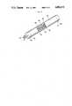
- FIG. 1is a perspective view, partly in cross section, of a sensor having a rod according to the present invention
- FIG. 2is a perspective view, partly broken away, which shows the interior construction of the rod
- FIG. 3is an end elevation view of the rod shown in FIG. 2,
- FIG. 4is a perspective view, partly broken away, which shows the interior construction of the rod of sensor element
- FIG. 5is a longitudinal section of a cover for the sensor
- FIG. 6is an elevation view, partly in cross section, of a fully assembled sensor according to the present invention.
- FIG. 1shows a sensor according to the present invention, which is formed by covering a sensor element 10 with a cover 40.
- a rod 12as shown in FIG. 2, has ten through holes 18 for thin metal wires, which holdes pass entirely through the rod in the longitudinal direction and are equally spaced with respect to each other along the circumference of the rod. Further, four through holes 22 are provided adjacent to the center portion (axis) of the rod and inside the disposition of the through holes 18 for the thin metal wires. A plurality of straight thin metal wires 20 are inserted into and pass through the through holes 18.
- the thin metal wires 20are bent in a U-shape at the back end 16 and a pair of end portions of each thin metal wire is inserted into and pass through a pair of through holes 18 adjacent to each other from the back end surface 16 to the front end surface 14 of the rod 12.
- five U-shape wires 20are inserted into and pass through each pair of through holes 18 for the wires, and at the front end surface 14 an end portion of one wire is properly connected, e.g. by the spot welding, to an end portion of other wire adjacent to the above end portion.
- wires 20are connected in series and, thus, at the front end surface 14 only one resistance differential is formed between an end portion 20A and an end portion 20B.
- two straight lead wires 24, 24are inserted into and pass through the through holes 22 for lead wires 24.
- the lead wires 24are also bent in U-shape in the same way as the above-mentioned method of the thin metal wire 20 and a pair of end portions of each lead wire are inserted into and pass through a pair of through holes 22 adjacent to each other, but, from the front end surface 14 to the back end surface 16 of the rod 12 which is opposite to the insertion of the thin metal wire 20.
- the end portions 20A, 20B of the thin metal wires 20are connected with contact points 26, 28 of the two lead wires 24, 24, e.g. by spot welding.
- the two lead wires 24, 24are connected with the contact points 26 and 28 whereby the electric resistance of the thin metal wire 20 may be measured by the known four terminal method.
- the thermal change of an atmosphere in which the sensor is disposedcan be determined by connecting a current source and a voltmeter with the lead wires, adequately electrifying the thin metal wires 20, simultaneously measuring a voltage between the contact points 26 and 28 and calculating the electric resistance of the thin metal wires 20.
- the thin metal wire 20 and the lead wire 24are of slightly smaller diameter than that of the through holes 18 and the lead wire holes 22.
- Ceramics powder 30are filled into the space in the through holes 18 and the lead wire holes 22.
- a glass sealing 32is provided to both the front end surface 14 and the back end surface 16 of the rod 12 in order to prevent leakage of the ceramics powder 30.
- the filled ceramics powder 30is sintered at a low temperature.
- the "low temperature”means a temperature lower than the sintering temperature of the ceramics.
- the ceramics powder 30 sintered at a low temperaturecan prevent an eccentricity of the thin metal wire 20. Further, when a volumetric expansion of the thin metal wire 20 occurs with heat, since the sintering state is easily destroyed, the thin metal wire 20 is not pressed against the inside of holes 18 and therefore no stress-strain occurs in the thin metal wire 20.
- the rod 12is a column having a 1.4mm diameter and 100mm length and made of a ceramics having a high purity (more than 99.9%) of a sintered crystallized alumina.
- the thin metal wire 20is a platinum wire having a 0.110mm diameter and the lead wire 22 is a platinum wire having a 0.15mm diameter. Holes 18 having a 0.16mm diameter are provided along the rod 12, and lead wire holes 22 having 0.16mm diameter are provided in the center of the rod 12.
- the rod 12 of ceramicsprovides high workability and high strength and the rod, therefore, is not changed in quality or deformed. Further, the coefficient of volumetric expansion thereof is more or less the same as that of platinum.
- the thin metal wire 20is made of platinum and provides stability of the electric resistance thereof.
- the electric resistance of such a sensoris 10 ⁇
- the platinum wire having 0.110mm diameteris 10 ⁇ /m and therefore the desired value is determined according to these values.
- the error of electric resistance of each sensor element 10is about ⁇ 0.1% and the electric resistance has high stability both with time and with a heating-cooling procedure.
- the lead wire 24is inserted into the center of rod 10 so that the lead wire 24 is not directly exposed to the temperature imposed on sensor element 10 in order to prevent a heat outflow from the lead wire 24. With this the heat of the thin metal wire 20 will not radiate out through the lead wire 24.
- stainless steelSUS 316L
- platinumpalladium and titanium are used as a pipe material; however, the pipe material is optionally determined in accordance with intended conditions.
- a vacuumis applied from the front end of the pipe 42A and a resin is filled into the cover 40 from the back end 42B thereof for electrically insulating it from open air.
- Ceramics powdere.g. magnesium oxide powder and so on can be filled into the cover 40 in place of resin.
- the lead wire 24can be connected to a cable 50 which is secured to cover 40 and a spring means 52 may be provided for protecting the cable 50 so as to obtain a sensor having excellent durability.
- the cover 40 described aboveis only one example of that which may be used as an electrically insulating cover for the sensor element 10 and is not a limitation on the construction of the present sensor, with the exception that the cover must be an electrically insulating cover for the sensor element 10.
- the senor according to the present inventioncan be applied for use as a resistance temperature sensor to measure the atmosphere in which the sensor is disposed by electrifying the thin metal wire, simultaneously measuring the voltage applied to the thin metal wire to obtain the change of the electric resistance.
- two sensors according to the present inventionare disposed in the fluid and one is used as a heat build-up element and another is used as a resistanct temperature sensor for measuring thermal conductivity so as to determine many of the properties of the fluid according to these values.
- the present inventioncan be applied in any field as desired.
Landscapes
- Chemical & Material Sciences (AREA)
- General Health & Medical Sciences (AREA)
- Pathology (AREA)
- Physics & Mathematics (AREA)
- Health & Medical Sciences (AREA)
- Life Sciences & Earth Sciences (AREA)
- Analytical Chemistry (AREA)
- Electrochemistry (AREA)
- General Physics & Mathematics (AREA)
- Biochemistry (AREA)
- Immunology (AREA)
- Chemical Kinetics & Catalysis (AREA)
- Investigating Or Analyzing Materials By The Use Of Electric Means (AREA)
- Measurement Of Length, Angles, Or The Like Using Electric Or Magnetic Means (AREA)
- Investigating Or Analyzing Materials Using Thermal Means (AREA)
- Measuring Temperature Or Quantity Of Heat (AREA)
Abstract
Description
Claims (11)
Applications Claiming Priority (2)
| Application Number | Priority Date | Filing Date | Title |
|---|---|---|---|
| JP62-201628 | 1987-08-12 | ||
| JP62201628AJPH0774790B2 (en) | 1987-08-12 | 1987-08-12 | Sensor used for electric heating method |
Publications (1)
| Publication Number | Publication Date |
|---|---|
| US4882571Atrue US4882571A (en) | 1989-11-21 |
Family
ID=16444219
Family Applications (1)
| Application Number | Title | Priority Date | Filing Date |
|---|---|---|---|
| US07/224,099Expired - LifetimeUS4882571A (en) | 1987-08-12 | 1988-07-26 | Sensor used for electrical heating measurement |
Country Status (8)
| Country | Link |
|---|---|
| US (1) | US4882571A (en) |
| EP (1) | EP0303116B1 (en) |
| JP (1) | JPH0774790B2 (en) |
| AU (1) | AU598150B2 (en) |
| CA (1) | CA1310513C (en) |
| DE (1) | DE3887027T2 (en) |
| DK (1) | DK171801B1 (en) |
| NZ (1) | NZ225544A (en) |
Cited By (3)
| Publication number | Priority date | Publication date | Assignee | Title |
|---|---|---|---|---|
| DE4026751A1 (en)* | 1989-08-30 | 1991-03-14 | Snow Brand Milk Products Co Ltd | Device for measuring concn. of soln. or suspension - heated probe is placed in pipe through which soln. is circulated, and concn. is derived from temp. difference between soln. and probe |
| US6127915A (en)* | 1997-03-19 | 2000-10-03 | Korea Research Institute Of Standards And Science | High temperature platinum resistance thermometer and method of producing such |
| US20220283039A1 (en)* | 2019-06-28 | 2022-09-08 | Fluke Corporation | Platinum resistance temperature sensor having floating platinum member |
Families Citing this family (3)
| Publication number | Priority date | Publication date | Assignee | Title |
|---|---|---|---|---|
| GB8600985D0 (en)* | 1986-01-16 | 1986-02-19 | Pyrontenax Of Canada Ltd | Electric cables |
| JP2921705B2 (en)* | 1990-06-06 | 1999-07-19 | 株式会社ネツシン | High temperature thermometer |
| JP7183875B2 (en)* | 2019-03-08 | 2022-12-06 | トヨタ自動車株式会社 | internal combustion engine |
Citations (5)
| Publication number | Priority date | Publication date | Assignee | Title |
|---|---|---|---|---|
| US3123790A (en)* | 1964-03-03 | tyler | ||
| US3286214A (en)* | 1963-02-02 | 1966-11-15 | Degussa | Measuring resistance |
| US3748624A (en)* | 1971-03-30 | 1973-07-24 | Nippon Denso Co | Pyrometric sensor using thermistor |
| US3761857A (en)* | 1971-10-04 | 1973-09-25 | Rosemount Inc | Resistance wire temperature sensor and method of making same |
| US4178544A (en)* | 1978-02-24 | 1979-12-11 | Teradyne, Inc. | Electrical measurement circuitry for low level AC signals |
Family Cites Families (13)
| Publication number | Priority date | Publication date | Assignee | Title |
|---|---|---|---|---|
| JPS4893885U (en)* | 1972-02-14 | 1973-11-09 | ||
| FR2188158A1 (en)* | 1972-06-14 | 1974-01-18 | Bailey Meter Co | |
| JPS5947716B2 (en)* | 1973-07-11 | 1984-11-21 | 旭硝子株式会社 | Organic solution type water and oil repellent with excellent durability |
| US4042901A (en)* | 1976-01-16 | 1977-08-16 | Robertshaw Controls Company | Temperature sensing resistance probe and method of making a resistance element therefor |
| JPS5535480A (en)* | 1978-09-05 | 1980-03-12 | Shiyuuichi Sakai | Heater |
| DE3313167A1 (en)* | 1983-04-12 | 1984-10-25 | Mantec Gesellschaft für Automatisierungs- und Handhabungssysteme mbH, 8510 Fürth | INDUSTRIAL ROBOT WITH ELECTRIC THREE-PHASE INDIVIDUAL DRIVES |
| JPS59217162A (en)* | 1983-05-25 | 1984-12-07 | Snow Brand Milk Prod Co Ltd | Measurement of milk coagulation |
| JPS6044990A (en)* | 1983-08-22 | 1985-03-11 | 株式会社日立製作所 | sheath heater |
| JPS60152943A (en)* | 1984-01-20 | 1985-08-12 | Snow Brand Milk Prod Co Ltd | Measurement of change in physical properties of liquid and semi-solid substance |
| JPH0697631B2 (en)* | 1984-12-22 | 1994-11-30 | 京セラ株式会社 | Ceramic heater and method for producing the same |
| JPS6218990U (en)* | 1985-07-19 | 1987-02-04 | ||
| JPS6256849A (en)* | 1985-09-06 | 1987-03-12 | Snow Brand Milk Prod Co Ltd | Sensor used for electric heating method |
| JPS62133344A (en)* | 1985-12-06 | 1987-06-16 | Kandenkou:Kk | Thermal resistance measurement method and device |
- 1987
- 1987-08-12JPJP62201628Apatent/JPH0774790B2/ennot_activeExpired - Fee Related
- 1988
- 1988-07-25NZNZ225544Apatent/NZ225544A/enunknown
- 1988-07-26USUS07/224,099patent/US4882571A/ennot_activeExpired - Lifetime
- 1988-07-29DEDE3887027Tpatent/DE3887027T2/ennot_activeExpired - Fee Related
- 1988-07-29EPEP88112283Apatent/EP0303116B1/ennot_activeExpired - Lifetime
- 1988-08-03CACA000573723Apatent/CA1310513C/ennot_activeExpired - Lifetime
- 1988-08-08AUAU20552/88Apatent/AU598150B2/ennot_activeCeased
- 1988-08-11DKDK449688Apatent/DK171801B1/ennot_activeIP Right Cessation
Patent Citations (5)
| Publication number | Priority date | Publication date | Assignee | Title |
|---|---|---|---|---|
| US3123790A (en)* | 1964-03-03 | tyler | ||
| US3286214A (en)* | 1963-02-02 | 1966-11-15 | Degussa | Measuring resistance |
| US3748624A (en)* | 1971-03-30 | 1973-07-24 | Nippon Denso Co | Pyrometric sensor using thermistor |
| US3761857A (en)* | 1971-10-04 | 1973-09-25 | Rosemount Inc | Resistance wire temperature sensor and method of making same |
| US4178544A (en)* | 1978-02-24 | 1979-12-11 | Teradyne, Inc. | Electrical measurement circuitry for low level AC signals |
Cited By (4)
| Publication number | Priority date | Publication date | Assignee | Title |
|---|---|---|---|---|
| DE4026751A1 (en)* | 1989-08-30 | 1991-03-14 | Snow Brand Milk Products Co Ltd | Device for measuring concn. of soln. or suspension - heated probe is placed in pipe through which soln. is circulated, and concn. is derived from temp. difference between soln. and probe |
| US6127915A (en)* | 1997-03-19 | 2000-10-03 | Korea Research Institute Of Standards And Science | High temperature platinum resistance thermometer and method of producing such |
| US20220283039A1 (en)* | 2019-06-28 | 2022-09-08 | Fluke Corporation | Platinum resistance temperature sensor having floating platinum member |
| US11815410B2 (en)* | 2019-06-28 | 2023-11-14 | Fluke Corporation | Platinum resistance temperature sensor having floating platinum member |
Also Published As
| Publication number | Publication date |
|---|---|
| AU2055288A (en) | 1989-02-16 |
| EP0303116B1 (en) | 1994-01-12 |
| DK449688D0 (en) | 1988-08-11 |
| DK171801B1 (en) | 1997-06-09 |
| CA1310513C (en) | 1992-11-24 |
| DK449688A (en) | 1989-02-13 |
| DE3887027D1 (en) | 1994-02-24 |
| JPS6444838A (en) | 1989-02-17 |
| JPH0774790B2 (en) | 1995-08-09 |
| NZ225544A (en) | 1990-08-28 |
| DE3887027T2 (en) | 1994-07-07 |
| EP0303116A2 (en) | 1989-02-15 |
| AU598150B2 (en) | 1990-06-14 |
| EP0303116A3 (en) | 1989-09-20 |
Similar Documents
| Publication | Publication Date | Title |
|---|---|---|
| US3614387A (en) | Electrical heater with an internal thermocouple | |
| EP0809090A1 (en) | Fluid thermal mass flow sensor | |
| US4575705A (en) | Temperature probe | |
| US4556475A (en) | Electrochemical gas sensor probe construction | |
| US4538927A (en) | Electrical temperature sensor, particularly for fever thermometer use | |
| EP2420807B1 (en) | Temperature sensor | |
| US6354150B1 (en) | Sensor for a capillary tube of a mass flow meter | |
| JP2001033295A (en) | Capacitive probe for measuring level of conductive liquid in container and method for manufacturing the probe | |
| US4882571A (en) | Sensor used for electrical heating measurement | |
| US5309133A (en) | Temperature sensor | |
| KR101255564B1 (en) | Pirani gauge | |
| EP0129120B1 (en) | Liquid level sensor | |
| JPH10148554A (en) | Flowmeter | |
| US6997604B2 (en) | Temperature sensor | |
| JPH04366727A (en) | Flow rate sensor | |
| KR19990037001A (en) | Methods for determining exhaust gas temperature and air-fuel ratio lambda and sensor arrangements for implementing such methods | |
| US4479026A (en) | Measuring resistor for a noise thermometer | |
| US5168256A (en) | Resistor element using conductors having relatively low thermal conductivity | |
| US4995731A (en) | Method for measuring heat transfer coefficient and sensor including heat transfer element and thermal insulation element | |
| US4011654A (en) | Exhaust gas sensor probe method of manufacture | |
| US3964314A (en) | Temperature-measuring instrument | |
| US6241865B1 (en) | Sensor for the measurement of gas concentrations | |
| JP2938700B2 (en) | Thermal flow meter | |
| Danilova et al. | R113 boiling heat transfer modeling on porous metallic matrix surfaces | |
| RU2126956C1 (en) | Heat flowmeter |
Legal Events
| Date | Code | Title | Description |
|---|---|---|---|
| AS | Assignment | Owner name:SNOW BRAND MILK PRODUCTS CO., LTD., NO. 1-1, NAEBO Free format text:ASSIGNMENT OF ASSIGNORS INTEREST.;ASSIGNORS:HORI, TOMOSHIGE;SHIINOKI, YASUHIKO;ITOH, KENSUKE;REEL/FRAME:004927/0074 Effective date:19880706 Owner name:SNOW BRAND MILK PRODUCTS CO., LTD., A CORP. OF JAP Free format text:ASSIGNMENT OF ASSIGNORS INTEREST;ASSIGNORS:HORI, TOMOSHIGE;SHIINOKI, YASUHIKO;ITOH, KENSUKE;REEL/FRAME:004927/0074 Effective date:19880706 | |
| FEPP | Fee payment procedure | Free format text:PAYOR NUMBER ASSIGNED (ORIGINAL EVENT CODE: ASPN); ENTITY STATUS OF PATENT OWNER: LARGE ENTITY | |
| STCF | Information on status: patent grant | Free format text:PATENTED CASE | |
| FPAY | Fee payment | Year of fee payment:4 | |
| FPAY | Fee payment | Year of fee payment:8 | |
| FEPP | Fee payment procedure | Free format text:PAYOR NUMBER ASSIGNED (ORIGINAL EVENT CODE: ASPN); ENTITY STATUS OF PATENT OWNER: LARGE ENTITY Free format text:PAYER NUMBER DE-ASSIGNED (ORIGINAL EVENT CODE: RMPN); ENTITY STATUS OF PATENT OWNER: LARGE ENTITY | |
| FPAY | Fee payment | Year of fee payment:12 |