US4878747A - Aperture image beam splitter - Google Patents
Aperture image beam splitterDownload PDFInfo
- Publication number
- US4878747A US4878747AUS07/302,112US30211289AUS4878747AUS 4878747 AUS4878747 AUS 4878747AUS 30211289 AUS30211289 AUS 30211289AUS 4878747 AUS4878747 AUS 4878747A
- Authority
- US
- United States
- Prior art keywords
- sample
- radiant energy
- aperture
- image plane
- optics
- Prior art date
- Legal status (The legal status is an assumption and is not a legal conclusion. Google has not performed a legal analysis and makes no representation as to the accuracy of the status listed.)
- Expired - Lifetime
Links
- 238000000034methodMethods0.000claimsdescription2
- 238000004611spectroscopical analysisMethods0.000claims7
- 230000003287optical effectEffects0.000abstractdescription23
- 230000000717retained effectEffects0.000abstractdescription2
- 238000005033Fourier transform infrared spectroscopyMethods0.000description5
- 238000000765microspectrophotometryMethods0.000description4
- 238000003384imaging methodMethods0.000description3
- 238000004519manufacturing processMethods0.000description2
- 230000004048modificationEffects0.000description2
- 238000012986modificationMethods0.000description2
- 241001061076Melanonus zugmayeriSpecies0.000description1
- 235000013290Sagittaria latifoliaNutrition0.000description1
- 230000004075alterationEffects0.000description1
- 235000015246common arrowheadNutrition0.000description1
- 238000000386microscopyMethods0.000description1
Images
Classifications
- G—PHYSICS
- G02—OPTICS
- G02B—OPTICAL ELEMENTS, SYSTEMS OR APPARATUS
- G02B27/00—Optical systems or apparatus not provided for by any of the groups G02B1/00 - G02B26/00, G02B30/00
- G02B27/10—Beam splitting or combining systems
- G02B27/14—Beam splitting or combining systems operating by reflection only
- G02B27/143—Beam splitting or combining systems operating by reflection only using macroscopically faceted or segmented reflective surfaces
- G—PHYSICS
- G01—MEASURING; TESTING
- G01N—INVESTIGATING OR ANALYSING MATERIALS BY DETERMINING THEIR CHEMICAL OR PHYSICAL PROPERTIES
- G01N21/00—Investigating or analysing materials by the use of optical means, i.e. using sub-millimetre waves, infrared, visible or ultraviolet light
- G01N21/17—Systems in which incident light is modified in accordance with the properties of the material investigated
- G01N21/25—Colour; Spectral properties, i.e. comparison of effect of material on the light at two or more different wavelengths or wavelength bands
- G01N21/31—Investigating relative effect of material at wavelengths characteristic of specific elements or molecules, e.g. atomic absorption spectrometry
- G01N21/35—Investigating relative effect of material at wavelengths characteristic of specific elements or molecules, e.g. atomic absorption spectrometry using infrared light
- G—PHYSICS
- G01—MEASURING; TESTING
- G01N—INVESTIGATING OR ANALYSING MATERIALS BY DETERMINING THEIR CHEMICAL OR PHYSICAL PROPERTIES
- G01N21/00—Investigating or analysing materials by the use of optical means, i.e. using sub-millimetre waves, infrared, visible or ultraviolet light
- G01N21/17—Systems in which incident light is modified in accordance with the properties of the material investigated
- G01N21/47—Scattering, i.e. diffuse reflection
- G01N21/4738—Diffuse reflection, e.g. also for testing fluids, fibrous materials
- G01N21/474—Details of optical heads therefor, e.g. using optical fibres
- G—PHYSICS
- G02—OPTICS
- G02B—OPTICAL ELEMENTS, SYSTEMS OR APPARATUS
- G02B17/00—Systems with reflecting surfaces, with or without refracting elements
- G02B17/02—Catoptric systems, e.g. image erecting and reversing system
- G02B17/06—Catoptric systems, e.g. image erecting and reversing system using mirrors only, i.e. having only one curved mirror
- G02B17/0605—Catoptric systems, e.g. image erecting and reversing system using mirrors only, i.e. having only one curved mirror using two curved mirrors
- G02B17/061—Catoptric systems, e.g. image erecting and reversing system using mirrors only, i.e. having only one curved mirror using two curved mirrors on-axis systems with at least one of the mirrors having a central aperture
- G—PHYSICS
- G02—OPTICS
- G02B—OPTICAL ELEMENTS, SYSTEMS OR APPARATUS
- G02B21/00—Microscopes
- G02B21/02—Objectives
- G02B21/04—Objectives involving mirrors
- G—PHYSICS
- G02—OPTICS
- G02B—OPTICAL ELEMENTS, SYSTEMS OR APPARATUS
- G02B21/00—Microscopes
- G02B21/06—Means for illuminating specimens
- G—PHYSICS
- G01—MEASURING; TESTING
- G01N—INVESTIGATING OR ANALYSING MATERIALS BY DETERMINING THEIR CHEMICAL OR PHYSICAL PROPERTIES
- G01N21/00—Investigating or analysing materials by the use of optical means, i.e. using sub-millimetre waves, infrared, visible or ultraviolet light
- G01N21/17—Systems in which incident light is modified in accordance with the properties of the material investigated
- G01N21/25—Colour; Spectral properties, i.e. comparison of effect of material on the light at two or more different wavelengths or wavelength bands
- G01N21/31—Investigating relative effect of material at wavelengths characteristic of specific elements or molecules, e.g. atomic absorption spectrometry
- G01N21/35—Investigating relative effect of material at wavelengths characteristic of specific elements or molecules, e.g. atomic absorption spectrometry using infrared light
- G01N2021/3595—Investigating relative effect of material at wavelengths characteristic of specific elements or molecules, e.g. atomic absorption spectrometry using infrared light using FTIR
Definitions
- the present inventionrelates to the general field of microscopy and particularly the field of fast Fourier-infrared (FT-IR) microspectrophotometry.
- FT-IRfast Fourier-infrared
- Copending U.S. patent application Ser. No. 707,231, now U.S. Pat. No. 4,653,880, title Reflective Beam Splitting Objectivediscloses an aperture beam splitter formed entirely with mirror optics.
- the mirror opticscan focus radiant energy having greatly differing wavelengths such as from the visible light region to the infrared.
- the beam splitterforms an integral unit with the imaging objective of the microscope.
- an intercepting mirroris positioned close to the secondary mirror of a Cassegrain reflective objective so as to divide in half the reflective surface of the secondary mirror.
- the intercepting mirrorreflects half of a beam of incident radiant energy to the secondary so that energy from half of the aperture of the primary mirror forms an image at an image sample plane.
- the other half of the primary mirrorcollects the radiant energy from the surface of the sample.
- the arrangement of mirrorsenables the reflective beam splitting objective to obtain a 50% throughput efficiency. Little if any of the image information about the sample is lost and the quality of the image is adequate for FT-IR microspectrophotometry.
- the reflective beam splitting objectiveunlike conventional aperture beam splitters, eliminates the complexity and expense associated with collimating optics. Rather than collimating the radiant energy, the reflecting beam splitting objective receives radiant energy that is either converging or diverging.
- the foregoing aperture beam splitterhas several disadvantages.
- the intercepting mirrormust be positioned in a confined space within the focusing objective.
- the relatively small physical dimensions of a microscope objectiveseverely limit the physical size of the intercepting mirror.
- the confined physical space within the objectivemakes aligning the intercepting mirror most critical.
- the difficulty associated with obtaining and maintaining the alignmentincreases the cost of the objective beam splitter.
- the integral structure of the reflective beam splitting objectiverequires that each microscope objective contain a properly aligned intercepting mirror. Commercially available reflecting objectives therefore cannot be used without expensive modification.
- the present inventionrelates to an improved aperture beam splitter.
- An intercepting mirroris positioned at an aperture image plane that is remote from any sample image.
- the aperture image planecorresponds to an aperture stop.
- Half of the beam of radiant energyis lost at the aperture image plane.
- the remaining energysupplies the input to an optical system.
- the output of the optical systemeventually returns to an image plane corresponding to the aperture imaging plane.
- the optical paths of the incident and returning radiant energyare sufficiently coincident in space that the aperture image plane returns to the intercepting mirror. If the optical system focuses the radiant energy an odd number of times, the aperture image experiences a mirror symmetry reversal.
- the energy that was retained in the optical system during the first pass through the aperture image planefills the other half of the aperture image plane.
- the intercepting mirrorcan separate the beam of incident radiant energy from the beam of returning radiant energy without additional loss of energy or loss of image information gained from an intervening focus.
- the improved aperture beam splitter according to the present inventionretains the advantages of the above identified reflective beam splitting objective without requiring a critical positioning of the intercepting mirror.
- the greater tolerancereduces the cost of manufacturing the beam splitter and simplifies the task of obtaining and maintaining a proper optical alignment.
- the aperture image beam splitterworks with all commercially available condensers and objectives and thus eliminates the time and expense associated with inserting and aligning an intercepting mirror in each microscope objective.
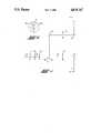
- FIG. 1is a schematic illustration of an aperture image beam splitter embodying the present invention.
- FIG. 2shows the distribution and direction of propagation of the radiant energy forming the aperture image at the intercepting mirror in FIG. 1.
- FIG. 1is a schematic illustration of an aperture image beam splitter embodying the present invention.
- a beam of radiant energy 1emanates from a source 2 to a detector system 3.
- the source 2 and detector system 3comprise parts of a fourier transform - infrared (FT-IR) spectrophotometer, many examples of which are well known in the art.
- Transfer opticscomprising mirror 4 reflect the radiant energy out of the sample compartment or "shoe box" of the spectrophotometer, not shown in FIG. 1.
- Additional transfer opticscomprising one or more mirrors, lenses, or combinations thereof and symbolically illustrated by double arrow 5, focus the radiant energy at first sample image 6.
- Half of the diverging beam of incident energy from first sample image 6fills surface 7a on intercepting mirror 7.
- Surface 7adiscards the energy from the first sample image plane 6 by reflecting it to one side.
- the other half of the beam of incident energypasses by intercepting mirror 7.
- Intercepting mirror 7is positioned at what is defined for the purpose of the present description as an aperture image plane 8.
- FIG. 2shows the distribution of intercepting the radiant energy at the aperture image plane. The direction of the radiant energy is shown using conventional arrow head and arrow tail notation. The beam of incident radiant energy that passes by intercepting mirror 7 fills input region 8a. The direction of propagation direction into the paper in FIG. 2 is indicated by the crosses symbolizing tails of the vector arrows.
- An optical systemsymbolically indicated by double arrow 9 in FIG. 1, focuses the incident beam of radiant energy at a second sample image 10.
- the optical systemmay also include an additional set of optics symbolically indicated by double arrow 11 to image the radiant energy at sample 12.
- the imaging optics indicated by double arrows 9 and 11may comprise one or more mirrors, lenses or combinations thereof. Mirror optics exhibit no chromatic aberration and are therefore preferred.
- the optical system formed by optics 9 and 11preferably comprise a microscope for FT-IR microspectrophotometry.
- optics 11image the radiant energy reflected from a sample 12 to the second sample image 10.
- the radiant energy from the sample reflected through the optical systemforms an aperture image 8b at the plane of mirror 7.
- the returning radiant energyis indicated as output 8b in FIG. 2 by the dots and circles which symbolize the heads of arrows.
- the aperture images 8a and 8bare mirror images whenever the radiant energy is focused at an odd number of sample image planes before returning to aperture plane 8. This result, however, requires that the image information carried by the radiant energy is not scrambled or otherwise destroyed.
- the radiant energy in the returning beam from the samplefills the area of the aperture image plane from which energy was originally removed at surface 7a at intercepting mirror 7.
- a reflecting surface 7bprovided on the back side of mirror 7, reflects the beam of returning radiant energy from the aperture image to transfer optics comprising mirror 13. Additional transfer optics, comprising one or more mirrors, lenses or combinations thereof and symbolically represented by double arrow 14, modify the divergence of the returning beam of radiant energy so that it is reflected by mirror 15 to a focus at detector system 3.
- Intercepting mirror 7must be positioned at a location that is remote from any sample image plane of the optical system, such as first sample image 6.
- Reflective surface 7apreferably corresponds to an aperture stop for the beam of incident radiant energy.
- the aperture imagecontains radiant energy from all the points of first sample image 6 because intercepting mirror 7 only reduces the effective aperture of the system. The image information gained at any of the sample images is therefore not vignetted by the intercepting mirror. However, the intercepting mirror does reduce the brightness of each subsequent image.
- the numerical aperture, and hence the effective resolution of any subsequent focusing optics,is also reduced so long as the radiant energy continues to transmit the image of the intercepting mirror at the aperture image plane.
- surface 7a of mirror 7intercept exactly one half of the beam of radiant energy as shown in FIG. 2. Intercepting more than one half of the radiant energy with mirror 7 is inefficient because radiant energy is wasted and the effective aperture is reduced. Conversely, intercepting less than one half of the radiant energy is also inefficient because the extra radiant energy cannot be directed to the detector on the return, thus reducing the effective numerical aperture of the optical system.
- An intermediate sample imagesuch as second sample image 10
- second sample image 10may be masked with a variable aperture diaphragm or set of razor blades to form an arbitrary geometric shape.
- the image of the maskis projected onto all other sample images in the optical system.
- the ability to mask an intermediate sample image and project the image of that remote sample image onto a sampleis considered a major utility of the present invention in the field of FT-IR microspectrophotometry.
- the reflectance mode microscope system shown in FIG. 1may be replaced by a transmissive mode microscope system.
- the intercepting mirrormay reflect the beam of incident radiant energy into the optical system rather than reflect the beam of returning radiant energy to the detector as done in the embodiment shown in FIG. 1.
- the intercepting mirror(s)may be positioned at any place in the optical path that is remote from a focus and preferably at an aperture stop.
- the intercepting mirrorhas no maximum size and may be positioned within comparatively wide tolerances. The wide tolerances greatly simplifies the process of aligning the intercepting mirror and reduce manufacturing costs while also maintaining the quality of the image. Additional transfer optics may be added to the optical system shown in FIG. 1 to accomplish any number of objectives or to simplify any other mechanical alignments.
Landscapes
- Physics & Mathematics (AREA)
- General Physics & Mathematics (AREA)
- Optics & Photonics (AREA)
- Chemical & Material Sciences (AREA)
- Analytical Chemistry (AREA)
- Spectroscopy & Molecular Physics (AREA)
- Health & Medical Sciences (AREA)
- Life Sciences & Earth Sciences (AREA)
- Biochemistry (AREA)
- General Health & Medical Sciences (AREA)
- Immunology (AREA)
- Pathology (AREA)
- Microscoopes, Condenser (AREA)
Abstract
Description
Claims (8)
Priority Applications (1)
| Application Number | Priority Date | Filing Date | Title |
|---|---|---|---|
| US07/302,112US4878747A (en) | 1985-03-01 | 1989-01-24 | Aperture image beam splitter |
Applications Claiming Priority (3)
| Application Number | Priority Date | Filing Date | Title |
|---|---|---|---|
| US06/707,231US4653880A (en) | 1985-03-01 | 1985-03-01 | Reflective beam splitting objective |
| US1358487A | 1987-02-11 | 1987-02-11 | |
| US07/302,112US4878747A (en) | 1985-03-01 | 1989-01-24 | Aperture image beam splitter |
Related Parent Applications (1)
| Application Number | Title | Priority Date | Filing Date |
|---|---|---|---|
| US1358487AContinuation | 1985-03-01 | 1987-02-11 |
Publications (1)
| Publication Number | Publication Date |
|---|---|
| US4878747Atrue US4878747A (en) | 1989-11-07 |
Family
ID=27359894
Family Applications (1)
| Application Number | Title | Priority Date | Filing Date |
|---|---|---|---|
| US07/302,112Expired - LifetimeUS4878747A (en) | 1985-03-01 | 1989-01-24 | Aperture image beam splitter |
Country Status (1)
| Country | Link |
|---|---|
| US (1) | US4878747A (en) |
Cited By (12)
| Publication number | Priority date | Publication date | Assignee | Title |
|---|---|---|---|---|
| US5011243A (en)* | 1986-09-16 | 1991-04-30 | Laser Precision Corporation | Reflectance infrared microscope having high radiation throughput |
| US5019715A (en)* | 1990-03-02 | 1991-05-28 | Spectra-Tech, Inc. | Optical system and method for sample analyzation |
| US5051602A (en)* | 1990-03-02 | 1991-09-24 | Spectra-Tech, Inc. | Optical system and method for sample analyzation |
| US5093580A (en)* | 1990-03-02 | 1992-03-03 | Spectra-Tech, Inc. | ATR objective and method for sample analyzation using an ATR crystal |
| US5200609A (en)* | 1991-08-27 | 1993-04-06 | Sting Donald W | Radiant energy spectroscopy system with diamond internal reflection element |
| US5225678A (en)* | 1991-11-13 | 1993-07-06 | Connecticut Instrument Corporation | Spectoscopic sampling accessory having dual measuring and viewing systems |
| US5239409A (en)* | 1986-09-16 | 1993-08-24 | Research-Cottrell Technologies, Inc. | Reflectance infrared microscope having high radiation throughput |
| US5394270A (en)* | 1992-10-19 | 1995-02-28 | Thyssen Stahl Aktiengesellschaft | Optical beam divider for a laser beam |
| US5581085A (en)* | 1995-03-06 | 1996-12-03 | Spectra-Tech, Inc. | Infrared microspectrometer accessory |
| US6434284B1 (en)* | 2000-12-07 | 2002-08-13 | Corning Incorporated | Beam converter for enhancing brightness of polarized light sources |
| US6693280B2 (en) | 2001-08-03 | 2004-02-17 | Sensir Technologies, L.L.C. | Mid-infrared spectrometer attachment to light microscopes |
| US20090103588A1 (en)* | 2006-06-13 | 2009-04-23 | Nikon Corporation | Microscope apparatus |
Citations (9)
| Publication number | Priority date | Publication date | Assignee | Title |
|---|---|---|---|---|
| CH359783A (en)* | 1958-06-20 | 1962-01-31 | Rueger Ernst A | Photoelectric scanning device for reflection light controls |
| US3411852A (en)* | 1963-11-06 | 1968-11-19 | Optical Coating Laboratory Inc | Optical monitoring apparatus which includes a reflector system for focusing light ona sample and for receiving light reflected from the sample |
| US3585281A (en)* | 1967-12-22 | 1971-06-15 | Printing Dev Inc | Apparatus for optically resolving the light derived from the scanning of a tonal image into color components |
| US3968362A (en)* | 1975-08-11 | 1976-07-06 | Honeywell Inc. | Optical system for laser doppler homodyne detection |
| DE2722787A1 (en)* | 1977-05-20 | 1978-11-23 | Schneider Co Optische Werke | LENS WITH A REFLECTIVE ELEMENT |
| US4479700A (en)* | 1981-06-22 | 1984-10-30 | Kuniomi Abe | Microscope |
| US4531054A (en)* | 1981-07-31 | 1985-07-23 | Asahi Kogaku Kogyo Kabushiki Kaisha | Wavefront light beam splitter |
| US4594509A (en)* | 1983-01-31 | 1986-06-10 | Bruker Analytische Messtechnik Gmbh | Infrared spectrometer |
| US4653880A (en)* | 1985-03-01 | 1987-03-31 | Spectra-Tech Inc. | Reflective beam splitting objective |
- 1989
- 1989-01-24USUS07/302,112patent/US4878747A/ennot_activeExpired - Lifetime
Patent Citations (9)
| Publication number | Priority date | Publication date | Assignee | Title |
|---|---|---|---|---|
| CH359783A (en)* | 1958-06-20 | 1962-01-31 | Rueger Ernst A | Photoelectric scanning device for reflection light controls |
| US3411852A (en)* | 1963-11-06 | 1968-11-19 | Optical Coating Laboratory Inc | Optical monitoring apparatus which includes a reflector system for focusing light ona sample and for receiving light reflected from the sample |
| US3585281A (en)* | 1967-12-22 | 1971-06-15 | Printing Dev Inc | Apparatus for optically resolving the light derived from the scanning of a tonal image into color components |
| US3968362A (en)* | 1975-08-11 | 1976-07-06 | Honeywell Inc. | Optical system for laser doppler homodyne detection |
| DE2722787A1 (en)* | 1977-05-20 | 1978-11-23 | Schneider Co Optische Werke | LENS WITH A REFLECTIVE ELEMENT |
| US4479700A (en)* | 1981-06-22 | 1984-10-30 | Kuniomi Abe | Microscope |
| US4531054A (en)* | 1981-07-31 | 1985-07-23 | Asahi Kogaku Kogyo Kabushiki Kaisha | Wavefront light beam splitter |
| US4594509A (en)* | 1983-01-31 | 1986-06-10 | Bruker Analytische Messtechnik Gmbh | Infrared spectrometer |
| US4653880A (en)* | 1985-03-01 | 1987-03-31 | Spectra-Tech Inc. | Reflective beam splitting objective |
Non-Patent Citations (2)
| Title |
|---|
| Analect, "Micro-FTIR Spectrometers and FTIR Microscopes" Advertising Brochure From Analect Instruments, Irvine Calif. |
| Analect, Micro FTIR Spectrometers and FTIR Microscopes Advertising Brochure From Analect Instruments, Irvine Calif.* |
Cited By (16)
| Publication number | Priority date | Publication date | Assignee | Title |
|---|---|---|---|---|
| US5239409A (en)* | 1986-09-16 | 1993-08-24 | Research-Cottrell Technologies, Inc. | Reflectance infrared microscope having high radiation throughput |
| US5011243A (en)* | 1986-09-16 | 1991-04-30 | Laser Precision Corporation | Reflectance infrared microscope having high radiation throughput |
| DE4042117B4 (en)* | 1990-03-02 | 2006-03-23 | Spectra-Tech, Inc., Stamford | Optical system and method for analyzing samples |
| US5019715A (en)* | 1990-03-02 | 1991-05-28 | Spectra-Tech, Inc. | Optical system and method for sample analyzation |
| US5051602A (en)* | 1990-03-02 | 1991-09-24 | Spectra-Tech, Inc. | Optical system and method for sample analyzation |
| US5093580A (en)* | 1990-03-02 | 1992-03-03 | Spectra-Tech, Inc. | ATR objective and method for sample analyzation using an ATR crystal |
| US5200609A (en)* | 1991-08-27 | 1993-04-06 | Sting Donald W | Radiant energy spectroscopy system with diamond internal reflection element |
| US5225678A (en)* | 1991-11-13 | 1993-07-06 | Connecticut Instrument Corporation | Spectoscopic sampling accessory having dual measuring and viewing systems |
| US5394270A (en)* | 1992-10-19 | 1995-02-28 | Thyssen Stahl Aktiengesellschaft | Optical beam divider for a laser beam |
| US5581085A (en)* | 1995-03-06 | 1996-12-03 | Spectra-Tech, Inc. | Infrared microspectrometer accessory |
| US6434284B1 (en)* | 2000-12-07 | 2002-08-13 | Corning Incorporated | Beam converter for enhancing brightness of polarized light sources |
| US6693280B2 (en) | 2001-08-03 | 2004-02-17 | Sensir Technologies, L.L.C. | Mid-infrared spectrometer attachment to light microscopes |
| US20040135084A1 (en)* | 2001-08-03 | 2004-07-15 | Sting Donald W. | Mid-infrared spectrometer attachment to light microscopes |
| US6972409B2 (en) | 2001-08-03 | 2005-12-06 | Smiths Detection Inc. | Mid-infrared spectrometer attachment to light microscopes |
| US20090103588A1 (en)* | 2006-06-13 | 2009-04-23 | Nikon Corporation | Microscope apparatus |
| US7628536B2 (en)* | 2006-06-13 | 2009-12-08 | Nikon Corporation | Microscope apparatus |
Similar Documents
| Publication | Publication Date | Title |
|---|---|---|
| US4653880A (en) | Reflective beam splitting objective | |
| US4512625A (en) | Scanner optics with no cross scan field curvature | |
| US5295143A (en) | Three color laser | |
| US4878747A (en) | Aperture image beam splitter | |
| US5210643A (en) | Wave combining apparatus for semiconductor lasers | |
| US5748365A (en) | Catadioptric one-to-one telecentric image combining system | |
| JPH02115814A (en) | Light beam scanning device | |
| US5517330A (en) | Minimization of differential bow in multiple beam scanning optical systems | |
| US5063292A (en) | Optical scanner with reduced end of scan wobble having an even number of beam reflections | |
| US4796965A (en) | Optical scanning device | |
| US4562462A (en) | Color laser printer with improved efficiency | |
| US5073016A (en) | Lens system for compact camera | |
| US6661447B2 (en) | Image-recording device for a printing form having macrooptics of the offner type | |
| US5028103A (en) | Optical scanning apparatus | |
| EP0278929B1 (en) | Alignment means for a light source emitting invisible laser light | |
| US4398787A (en) | Optical leverage telecentric scanning apparatus | |
| US4993812A (en) | Semiconductor laser optical system | |
| EP0345297B1 (en) | Aperture image beam splitter | |
| US4407563A (en) | High speed multi focal plane optical system | |
| US4444464A (en) | Dual aperture multispectral Schmidt objective | |
| US4289377A (en) | Projecting apparatus | |
| US6108115A (en) | Scanning optical system | |
| US5634159A (en) | Interferential multistereoscopic camera with three-dimensional effect | |
| JP2813123B2 (en) | Method and apparatus for combining arrays of rays | |
| US5812585A (en) | Method and arrangement for adjusting a mirror to a laser resonator |
Legal Events
| Date | Code | Title | Description |
|---|---|---|---|
| STCF | Information on status: patent grant | Free format text:PATENTED CASE | |
| FEPP | Fee payment procedure | Free format text:PAT HLDR NO LONGER CLAIMS SMALL ENT STAT AS INDIV INVENTOR (ORIGINAL EVENT CODE: LSM1); ENTITY STATUS OF PATENT OWNER: LARGE ENTITY | |
| FEPP | Fee payment procedure | Free format text:PAYOR NUMBER ASSIGNED (ORIGINAL EVENT CODE: ASPN); ENTITY STATUS OF PATENT OWNER: LARGE ENTITY Free format text:PAYER NUMBER DE-ASSIGNED (ORIGINAL EVENT CODE: RMPN); ENTITY STATUS OF PATENT OWNER: LARGE ENTITY | |
| FPAY | Fee payment | Year of fee payment:4 | |
| FEPP | Fee payment procedure | Free format text:PAYER NUMBER DE-ASSIGNED (ORIGINAL EVENT CODE: RMPN); ENTITY STATUS OF PATENT OWNER: LARGE ENTITY Free format text:PAT HOLDER CLAIMS SMALL ENTITY STATUS - SMALL BUSINESS (ORIGINAL EVENT CODE: SM02); ENTITY STATUS OF PATENT OWNER: LARGE ENTITY | |
| FPAY | Fee payment | Year of fee payment:8 | |
| REFU | Refund | Free format text:REFUND - PAYMENT OF MAINTENANCE FEE, 8TH YR, SMALL ENTITY (ORIGINAL EVENT CODE: R284); ENTITY STATUS OF PATENT OWNER: LARGE ENTITY | |
| FPAY | Fee payment | Year of fee payment:12 | |
| AS | Assignment | Owner name:THERMO ELECTRON SCIENTIFC INSTRUMENTS CORPORATION, Free format text:ASSIGNMENT OF ASSIGNORS INTEREST;ASSIGNOR:THERMO NICOLET CORPORATION;REEL/FRAME:016059/0291 Effective date:20030226 Owner name:THERMO SPECTRA-TECH, INC., CONNECTICUT Free format text:CHANGE OF NAME;ASSIGNOR:SPECTRA-TECH, INC.;REEL/FRAME:016059/0366 Effective date:20001026 Owner name:THERMO NICOLET CORPORATION, WISCONSIN Free format text:MERGER;ASSIGNOR:THERMO SPECTRA-TECH INC.;REEL/FRAME:016059/0619 Effective date:20020903 |