US4878698A - Restraining pipe joint - Google Patents
Restraining pipe jointDownload PDFInfo
- Publication number
- US4878698A US4878698AUS07/257,241US25724188AUS4878698AUS 4878698 AUS4878698 AUS 4878698AUS 25724188 AUS25724188 AUS 25724188AUS 4878698 AUS4878698 AUS 4878698A
- Authority
- US
- United States
- Prior art keywords
- gland
- bell
- shoulder
- pipe
- pipe end
- Prior art date
- Legal status (The legal status is an assumption and is not a legal conclusion. Google has not performed a legal analysis and makes no representation as to the accuracy of the status listed.)
- Expired - Lifetime
Links
- 230000000452restraining effectEffects0.000titleclaimsabstractdescription16
- 210000004907glandAnatomy0.000claimsabstractdescription50
- 230000002093peripheral effectEffects0.000claimsabstractdescription13
- 239000004033plasticSubstances0.000claimsabstractdescription11
- 229910001369BrassInorganic materials0.000claimsdescription10
- 239000010951brassSubstances0.000claimsdescription10
- 239000002184metalSubstances0.000claimsdescription5
- 229910052751metalInorganic materials0.000claimsdescription5
- 238000012856packingMethods0.000claimsdescription3
- 230000006835compressionEffects0.000claims1
- 238000007906compressionMethods0.000claims1
- 230000000712assemblyEffects0.000abstract2
- 238000000429assemblyMethods0.000abstract2
- 229910001018Cast ironInorganic materials0.000description4
- 230000013011matingEffects0.000description2
- 229910001208Crucible steelInorganic materials0.000description1
- 229910001060Gray ironInorganic materials0.000description1
- 239000004568cementSubstances0.000description1
- 230000000694effectsEffects0.000description1
- 239000000463materialSubstances0.000description1
- 238000007789sealingMethods0.000description1
- 239000010959steelSubstances0.000description1
- 239000011800void materialSubstances0.000description1
- XLYOFNOQVPJJNP-UHFFFAOYSA-NwaterSubstancesOXLYOFNOQVPJJNP-UHFFFAOYSA-N0.000description1
Images

Classifications
- F—MECHANICAL ENGINEERING; LIGHTING; HEATING; WEAPONS; BLASTING
- F16—ENGINEERING ELEMENTS AND UNITS; GENERAL MEASURES FOR PRODUCING AND MAINTAINING EFFECTIVE FUNCTIONING OF MACHINES OR INSTALLATIONS; THERMAL INSULATION IN GENERAL
- F16L—PIPES; JOINTS OR FITTINGS FOR PIPES; SUPPORTS FOR PIPES, CABLES OR PROTECTIVE TUBING; MEANS FOR THERMAL INSULATION IN GENERAL
- F16L21/00—Joints with sleeve or socket
- F16L21/08—Joints with sleeve or socket with additional locking means
Definitions
- Pipe jointsparticularly a restraining joint for use in a bell and plain pipe end assembly, using a metallic gland and plastic pipe, together with a gripping ring and compressible gasket interposed between the bell and the gland.
- the restraining jointrestrains the abutting plastic pipe ends against axial movement under varying hydraulic pressure. Thereby, the restraining joint overcomes a principal difficulty in fitting hose line connections to municipal water systems.
- a restraining pipe joint for use in a bell and plain pipe end assemblycomprising a gland encircling the plain end of the pipe and a split ring encircling the plain end of the pipe in juxtaposition with the gland and a compressible gasket. Compressing of the gland with respect to the bell forces the split ring into a conical aperture in the gland, thus gripping the pipe with constant pressure and precluding axial movement of the pipe within the fitting.
- the relationship in assembly of contiguous surfaces of gland, split ring and gasketis critical.
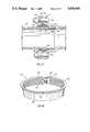
- FIG. 1is an exploded, vertical section of the gland, split ring, gasket and bell components in the restraining joint.
- FIG. 2is a fragmentary vertical view, showing fitting of the plain pipe end within the gland, split ring, gasket and bell components, precedent to complete assembly.
- FIG. 3is a fragmentary vertical section, showing the gland, split ring and gasket in complete assembly with bell and a plastic plain pipe end wherein the gasket is compressed between the gland, plain pipe end and bell components.
- FIG. 4is a perspective view of a metal brass split ring.
- FIG. 1there is illustrated a somewhat conventional metal pipe bell 10 having peripheral flange 16 with apertures 12, 12' for securing bolts and a first inner shoulder 18 complementally engagable with inclined inner shoulder 22 of compressible gasket 20.
- the bell interiordefines an opening wall of maximum radius relative to a center line of the joint, joining in a first conical shoulder 18 of declining radius said first conical shoulder terminating rearwardly in a second shoulder 18' of shortest radius, whereby to form within the bell a rearwardly extending recess 18" for the plain pipe end.
- Gasket 20has an opposed inclined outer shoulder 22'.
- a cast iron or similar gland 24 having peripheral apertures 26, 26' aligned with bell apertures 12, 12'is shown as having a conical, axial aperture 30 which terminates short of its forward end to form in extension thereof an inclined peripheral abutment 30'.
- An elongated brass split ring 36defines a conical exterior surface wall 32, which is complementally engagable by inner conical surface or aperture 30 of gland 24.
- This split ring 36also defines a peripheral flange 34 with its forward inclined shoulder 38 of positive slope relative to a centerline of the pipe end, the same being engagable with the opposed inclined shoulder 22' of compressible gasket 20. As shown in FIGS. 2 and 3, the peripheral flange 34 of the split ring projects outwardly of the plain pipe end 42.
- the flange 34thus further consists of two connected elements, namely at its forward end, an outer first elongated and inclined shoulder 38 which is inclined at a lesser angle than its inner rearward counterpart 38'.
- the angular disposition of shoulders 38, 38'is such that shoulder 38' is of greater inclination relative to a centerline of pipe axis.
- Shoulder 30' of the gland and opposed shoulder 38' of the split ringare in such complemental angular relationship that upon assembly they obtain maximum contiguous contact. They approximate parallelism.
- the shoulder 38'is also shown to connect with the conical surface 32 of the split ring and comprises an extension thereof. As will appear hereinafter, these elements 38 and 38' of the split ring are correspondingly engageable with substantially parallel elements 22' and 30' respectively of the gasket and gland. See FIG. 3.
- split ring 36has a longitudinally extending gap or split 39 so as to be coaxially compressible within the gland conical aperture 30, and its inclined peripheral abutment 30'. Also, inner teeth 37 of the ring are forwardly inclined so as to grip the plain pipe end both as gland 24 and bell 16 are compressed towards each other and as the pressure within the plastic pipe expands the diameter of the pipe.
- gland 24 inner surface 30complementally engages the outer conical surface 32 of the split ring as the bolts 48, 50 are placed through apertures 12, 12', 26, 26' and are tightened by means of nuts 52, 54.
- the inclined peripheral abutment 30' of gland 24engages its counterpart, the rearward extending shoulder 38' of the split ring 36.
- the assemblyis shown tightened and compressed in FIG. 3 with split ring teeth 37 engaging the plastic pipe 42.
- the gland abutment against the split ringprecludes shifting of the ring and compressible gasket 20, notwithstanding hydraulic pressure variations in the line flow.
- the engagement of teeth 37 into the plastic pipe 42likewise prevents longitudinal movement due to varying hydraulic pressurization or other stress.
- applicant's gland 24is slipped onto the plain end of the pipe with conical cavity 30 and peripheral gland abutment 30' facing outwardly.
- Brass split ring 36is slipped onto the pipe end with outer shoulder 38 of flange 34 facing outwardly and inner shoulder 38' facing inwardly.
- Standard mechanical joint rubber packing ring gasket 20is then placed on the pipe and positioned, so as to leave about 3/4" of the plain pipe end exposed.
- Split ring 36is then positioned, so that the outer shoulder 38 of its flange 34 is pushed tightly against corresponding parallel shoulder 22' of rubber gasket 20, and the pipe is then pushed into the bell fitting with rubber gasket 20, its shoulder 22 being urged onto a first inner shoulder 18 defined within the bell socket.
- Gland 24is then pushed up, and its conical surfaces 30 and 30' mate with the outside conical surfaces 32 and 38' of brass ring 36.
- Brass split ring 36having been expanded as it goes over the pipe, its O.D. is now larger than the corresponding inside surfaces of gland 24. Ring 36 thus lacks 1/2" or so of completely entering the gland aperture 30 and its shoulder extension 30'.
- the substantial parallelism which is established between opposed contacting and corresponding surfaces of gland, split ring, gasket and bellinsures the initial filling of the void between bell interior and plain pipe end.
- the final sealing effect of the restraining jointis most clearly shown in the sequential assembly step of FIG. 3.
- Standard mechanical bolts 48, 50are engaged through mating holes 12, 12' and 26, 26' in gland and pipe fitting. Now, as bolts 48, 50 are tightened, gland 24 is drawn inwardly toward bell 16, forcing flange outer periphery 34 of the ring 36 and its shoulder 38 against inclined rubber packing ring surface 22' thereby forcing brass ring 36 further into conical cavity 30 and extension 30' of gland 24. This assembly action continues until brass split ring 36 has thus been pushed into gland 24 completely, and ring flange shoulder 38' is integral with gland surface 30'. See FIGS. 2 and 3. The complemental, substantial parallelism of opposed contacting and corresponding surfaces of gland, split ring, gasket and bell facilitate meeting the advantages set forth below.
- Rubber gasket 20is now tightly compressed into bell socket 16, and as split ring 36 is forced deeper into gland 24 conical cavity 30, 30', the split ring teeth 37 are compressed into the pipe end.
- Split ring 36is now anchored within the pipe, flange periphery 34, and shoulder 38 are seated against the corresponding face 22' of gasket 20. Since no further axial movement of split ring 36 is mechanically possible, a tight restrained joint is formed.
- split ring 36Since the brass split ring 36 is compressed evenly for 360° of the circumference of the pipe end, split ring 36 is uniquely suited for use on plastic pipe. It works equally well, however, on cast iron, steel and like metal pipes. See FIG. 2.
- the inclined tooth 37 designallows split ring 36 to be pushed onto the pipe end very easily, but it grips tightly when pressure is applied axially in the opposite direction.
- the restraining jointis self-adjusting. In the event that the bolts 48, 50 are not tightened enough to fully seat ring 36, any pull-out pressure will pull the ring 36 deeper into the gland conical aperture 30 and against its inclined peripheral surface 30', thus tightening the grip on the pipe end until the flange 34 comes into contact with the gland which mechanically stops further movement.
- the glandmay be made of other materials than cast iron and the split ring may be manufactured from any suitable metal or plastic capable of gripping plastic pipe.
Landscapes
- Engineering & Computer Science (AREA)
- General Engineering & Computer Science (AREA)
- Mechanical Engineering (AREA)
- Flanged Joints, Insulating Joints, And Other Joints (AREA)
Abstract
Description
Applicant filed Disclosure Document No. 134,430on Jan. 28, 1985.
The present application comprises a continuation-in-part of patent application Ser. No. 002,322, filed 01/12/87, entitled RESTRAINING PIPE JOINT now abandoned.
1. Field of the Invention
Pipe joints, particularly a restraining joint for use in a bell and plain pipe end assembly, using a metallic gland and plastic pipe, together with a gripping ring and compressible gasket interposed between the bell and the gland. The restraining joint restrains the abutting plastic pipe ends against axial movement under varying hydraulic pressure. Thereby, the restraining joint overcomes a principal difficulty in fitting hose line connections to municipal water systems.
2. Description of the Prior Art
The prior art is considered to be shown by the following references:
______________________________________ UNITED STATES ______________________________________ CLARK 1,423,754 BANTA 1,556,745 CARSON 1,588,444 LUCAS 1,868,014 BRONSELL 2,070,855 FRANCES 2,347,044 LAMONT 2,349,180 PARKER et al. 2,351,363 DIES 2,396,163 JUNGBLUT 2,711,913 SUMMERS 2,832,615 SCHRODER 3,498,647 MANTON 3,652,110 HAMMER et al. 3,848,905 O'BRIEN et al. 3,869,156 BABB Jr. 3,920,270 DAVIS 4,062,572 REICH et al. 4,043,576 RIEFFL et al. 4,119,335 WYSS 4,183,560 NIELSEN, Jr. 4,256,335 LEGRIS 4,309,050 BATTLE et al. 4,540,204 HALEN et al. 4,610,471 ______________________________________ FOREIGN ______________________________________ SWITZERLAND 369,940 GT. BRITAIN 2,157,785 ______________________________________
A restraining pipe joint for use in a bell and plain pipe end assembly, comprising a gland encircling the plain end of the pipe and a split ring encircling the plain end of the pipe in juxtaposition with the gland and a compressible gasket. Compressing of the gland with respect to the bell forces the split ring into a conical aperture in the gland, thus gripping the pipe with constant pressure and precluding axial movement of the pipe within the fitting. The relationship in assembly of contiguous surfaces of gland, split ring and gasket is critical.
FIG. 1 is an exploded, vertical section of the gland, split ring, gasket and bell components in the restraining joint.
FIG. 2 is a fragmentary vertical view, showing fitting of the plain pipe end within the gland, split ring, gasket and bell components, precedent to complete assembly.
FIG. 3 is a fragmentary vertical section, showing the gland, split ring and gasket in complete assembly with bell and a plastic plain pipe end wherein the gasket is compressed between the gland, plain pipe end and bell components.
FIG. 4 is a perspective view of a metal brass split ring.
In FIG. 1 there is illustrated a somewhat conventionalmetal pipe bell 10 havingperipheral flange 16 withapertures 12, 12' for securing bolts and a firstinner shoulder 18 complementally engagable with inclinedinner shoulder 22 ofcompressible gasket 20. The bell interior defines an opening wall of maximum radius relative to a center line of the joint, joining in a firstconical shoulder 18 of declining radius said first conical shoulder terminating rearwardly in a second shoulder 18' of shortest radius, whereby to form within the bell a rearwardly extendingrecess 18" for the plain pipe end.Gasket 20 has an opposed inclined outer shoulder 22'. A cast iron orsimilar gland 24 havingperipheral apertures 26, 26' aligned withbell apertures 12, 12' is shown as having a conical,axial aperture 30 which terminates short of its forward end to form in extension thereof an inclined peripheral abutment 30'. An elongatedbrass split ring 36 defines a conicalexterior surface wall 32, which is complementally engagable by inner conical surface oraperture 30 ofgland 24. Thissplit ring 36 also defines aperipheral flange 34 with its forwardinclined shoulder 38 of positive slope relative to a centerline of the pipe end, the same being engagable with the opposed inclined shoulder 22' ofcompressible gasket 20. As shown in FIGS. 2 and 3, theperipheral flange 34 of the split ring projects outwardly of theplain pipe end 42. Theflange 34 thus further consists of two connected elements, namely at its forward end, an outer first elongated andinclined shoulder 38 which is inclined at a lesser angle than its inner rearward counterpart 38'. In short, the angular disposition ofshoulders 38, 38' is such that shoulder 38' is of greater inclination relative to a centerline of pipe axis. Shoulder 30' of the gland and opposed shoulder 38' of the split ring are in such complemental angular relationship that upon assembly they obtain maximum contiguous contact. They approximate parallelism. The shoulder 38' is also shown to connect with theconical surface 32 of the split ring and comprises an extension thereof. As will appear hereinafter, theseelements 38 and 38' of the split ring are correspondingly engageable with substantially parallel elements 22' and 30' respectively of the gasket and gland. See FIG. 3.
As illustrated in FIG. 4,split ring 36 has a longitudinally extending gap or split 39 so as to be coaxially compressible within the glandconical aperture 30, and its inclined peripheral abutment 30'. Also,inner teeth 37 of the ring are forwardly inclined so as to grip the plain pipe end both asgland 24 andbell 16 are compressed towards each other and as the pressure within the plastic pipe expands the diameter of the pipe.
As best illustrated in the FIG. 2 assembly,gland 24inner surface 30 complementally engages the outerconical surface 32 of the split ring as thebolts apertures nuts gland 24 engages its counterpart, the rearward extending shoulder 38' of thesplit ring 36.
As indicated heretofore, the assembly is shown tightened and compressed in FIG. 3 withsplit ring teeth 37 engaging theplastic pipe 42. The gland abutment against the split ring precludes shifting of the ring andcompressible gasket 20, notwithstanding hydraulic pressure variations in the line flow. The engagement ofteeth 37 into theplastic pipe 42 likewise prevents longitudinal movement due to varying hydraulic pressurization or other stress.
Referring to FIG. 2, applicant'sgland 24 is slipped onto the plain end of the pipe withconical cavity 30 and peripheral gland abutment 30' facing outwardly.Brass split ring 36 is slipped onto the pipe end withouter shoulder 38 offlange 34 facing outwardly and inner shoulder 38' facing inwardly. Standard mechanical joint rubberpacking ring gasket 20 is then placed on the pipe and positioned, so as to leave about 3/4" of the plain pipe end exposed.Split ring 36 is then positioned, so that theouter shoulder 38 of itsflange 34 is pushed tightly against corresponding parallel shoulder 22' ofrubber gasket 20, and the pipe is then pushed into the bell fitting withrubber gasket 20, itsshoulder 22 being urged onto a firstinner shoulder 18 defined within the bell socket. Gland 24 is then pushed up, and itsconical surfaces 30 and 30' mate with the outsideconical surfaces 32 and 38' ofbrass ring 36.Brass split ring 36 having been expanded as it goes over the pipe, its O.D. is now larger than the corresponding inside surfaces ofgland 24.Ring 36 thus lacks 1/2" or so of completely entering thegland aperture 30 and its shoulder extension 30'. In this initial assembly step of FIG. 2, the substantial parallelism which is established between opposed contacting and corresponding surfaces of gland, split ring, gasket and bell insures the initial filling of the void between bell interior and plain pipe end. The final sealing effect of the restraining joint is most clearly shown in the sequential assembly step of FIG. 3.
Standardmechanical bolts mating holes bolts gland 24 is drawn inwardly towardbell 16, forcing flangeouter periphery 34 of thering 36 and itsshoulder 38 against inclined rubber packing ring surface 22' thereby forcingbrass ring 36 further intoconical cavity 30 and extension 30' ofgland 24. This assembly action continues untilbrass split ring 36 has thus been pushed intogland 24 completely, and ring flange shoulder 38' is integral with gland surface 30'. See FIGS. 2 and 3. The complemental, substantial parallelism of opposed contacting and corresponding surfaces of gland, split ring, gasket and bell facilitate meeting the advantages set forth below.Rubber gasket 20 is now tightly compressed intobell socket 16, and assplit ring 36 is forced deeper intogland 24conical cavity 30, 30', thesplit ring teeth 37 are compressed into the pipe end.Split ring 36 is now anchored within the pipe,flange periphery 34, andshoulder 38 are seated against the corresponding face 22' ofgasket 20. Since no further axial movement ofsplit ring 36 is mechanically possible, a tight restrained joint is formed.
Advantages of applicant's invention include:
1. The restrained joint works well with all standard mechanical joint bells, as described in A.N.S.I. A 21.11 --(AWWA C111) Specifications.
2. Since thebrass split ring 36 is compressed evenly for 360° of the circumference of the pipe end, splitring 36 is uniquely suited for use on plastic pipe. It works equally well, however, on cast iron, steel and like metal pipes. See FIG. 2.
3. Theinclined tooth 37 design allows splitring 36 to be pushed onto the pipe end very easily, but it grips tightly when pressure is applied axially in the opposite direction.
4. The restraining joint is self-adjusting. In the event that thebolts ring 36, any pull-out pressure will pull thering 36 deeper into the glandconical aperture 30 and against its inclined peripheral surface 30', thus tightening the grip on the pipe end until theflange 34 comes into contact with the gland which mechanically stops further movement.
When applicant's combination ofbrass split ring 36 andmating gland 24 is substituted for a conventional gland in any cast iron fitting having standard AWWA Mechanical Joint, a restrained joint is produced. This precludes the need for further restraint which in the past has necessitated the use of tie rods, pouring of cement blocks, weights and the like in the municipal setting of fire hydrants, elbow fittings, and other connecting fittings. Applicant has developed styles for fitting C900 PVC pipe, as well as SDR PVC pipe. It is recommended thatgland 24 be fabricated from 30,000 psi gray iron and the recommended torque onbolts
The gland may be made of other materials than cast iron and the split ring may be manufactured from any suitable metal or plastic capable of gripping plastic pipe.
Manifestly, the configuration of both the split ring and gland may be modified without departing from the spirit and scope of the invention.
Claims (4)
1. A restraining pipe joint for use in a bell and plain pipe end assembly comprising:
a. a plain pipe end of plastic;
b. a bell which defines an opening wall of maximum radius relative to a center line of the joint, said opening wall joining a first conical shoulder of declining radius, a second shoulder of shortest radius, joining the first shoulder rearwardly to form within the bell a recess for the plain pipe end;
c. a gland encircling the plain pipe end, said gland defining a conical axial aperture interior wall which terminates short of its forward end forming in extension thereof an inclined interior peripheral abutment;
d. an elongated split ring likewise encircling the plain pipe end in juxtaposition with said gland and including:
i. a conical exterior wall complementally engageable by the conical axial aperture interior wall of said gland,
ii. a peripheral flange in forward extension of the conical exterior wall, directed outwardly from the plain pipe end, said flange defining at its end a forwardly inclined outer shoulder of positive angle relative to the center line of the joint and an inner rearwardly inclined inner shoulder of greater positive angle than the outer said shoulder of the flange, the inner shoulder of the flange being contiguously engageable by the inclined, interior peripheral abutment of the gland.
iii. a plurality of inwardly extending pipe end gripping teeth forming the inner surface of said split-ring, and
e. a compressible gasket encircling the plain pipe end, interposed between said split ring flange and the bell, said gasket defining a forwardly inclined packing ring shoulder, engageable in parallel with the forwardly inclined outer shoulder of said split-ring flange and an inwardly inclined outer shoulder, complementally contiguous with the first shoulder of the bell;
f. tightening means interconnecting said gland and the bell compressibly securing said gasket and said split-ring assembly within the pipe joint.
2. A restraining pipe joint for use in a bell and plain pipe end assembly as in claim 1, wherein said split ring upon compression has an inner diameter less than the outer diameter of said pipe, such that said gripping teeth bite into the pipe.
3. A restraining pipe joint for use in a bell and plain pipe end assembly as in claim 1, wherein said split ring is metal.
4. A restraining pipe joint for use in a bell and plain pipe end assembly as in either claim 1, 2 or 3, wherein said split ring is brass.
Priority Applications (1)
| Application Number | Priority Date | Filing Date | Title |
|---|---|---|---|
| US07/257,241US4878698A (en) | 1987-01-12 | 1988-10-13 | Restraining pipe joint |
Applications Claiming Priority (2)
| Application Number | Priority Date | Filing Date | Title |
|---|---|---|---|
| US232287A | 1987-01-12 | 1987-01-12 | |
| US07/257,241US4878698A (en) | 1987-01-12 | 1988-10-13 | Restraining pipe joint |
Related Parent Applications (1)
| Application Number | Title | Priority Date | Filing Date |
|---|---|---|---|
| US232287AContinuation-In-Part | 1987-01-12 | 1987-01-12 |
Publications (1)
| Publication Number | Publication Date |
|---|---|
| US4878698Atrue US4878698A (en) | 1989-11-07 |
Family
ID=26670230
Family Applications (1)
| Application Number | Title | Priority Date | Filing Date |
|---|---|---|---|
| US07/257,241Expired - LifetimeUS4878698A (en) | 1987-01-12 | 1988-10-13 | Restraining pipe joint |
Country Status (1)
| Country | Link |
|---|---|
| US (1) | US4878698A (en) |
Cited By (51)
| Publication number | Priority date | Publication date | Assignee | Title |
|---|---|---|---|---|
| US5056755A (en)* | 1990-07-26 | 1991-10-15 | Jang Young H | Gate valve |
| US5205356A (en)* | 1990-12-27 | 1993-04-27 | Abb Vetco Gray Inc. | Well starter head |
| US5207459A (en)* | 1991-07-11 | 1993-05-04 | Dresser Industries, Inc. | Transition coupling for pipes |
| WO1994002770A1 (en)* | 1992-07-23 | 1994-02-03 | Pont-A-Mousson S.A. | Seal locked between engaged tubular members |
| US5335946A (en)* | 1992-07-28 | 1994-08-09 | Romac Industries Inc. | Cooperating combination of a gland and a grip ring installed in restrained sealed bolted joints of fluid piping systems including both plastic pipe and metallic pipe |
| US5340169A (en)* | 1991-10-14 | 1994-08-23 | Pont-A-Mousson S.A. | Locking device for laid pipes with embedded insert |
| US5398980A (en)* | 1993-11-16 | 1995-03-21 | Tyler Pipe Industries, Inc. | Mechanical pipe joint |
| EP0670447A1 (en)* | 1994-03-01 | 1995-09-06 | Georg Fischer WAGA N.V. | Pipe coupling |
| WO1995033948A1 (en)* | 1994-06-06 | 1995-12-14 | Certainteed Corporation | Mechanical joint pipe adapter |
| US5484171A (en)* | 1991-09-24 | 1996-01-16 | Emmins; Douglas H. | Coupling joint |
| US5511826A (en)* | 1994-06-06 | 1996-04-30 | Certainteed Corporation | Towable nonconductive pipe adapter for a sprinkler having laterally extending surfaces |
| WO1996027752A1 (en)* | 1995-03-08 | 1996-09-12 | Hepworth Building Products Limited | Spigot and socket joint |
| WO1997025563A1 (en)* | 1996-01-09 | 1997-07-17 | Gebo-Armaturen Gmbh | Detachable pipe joint for plastic pipes |
| US5829793A (en)* | 1996-07-05 | 1998-11-03 | Phillips Petroleum Company | Self-restrained adapter system for connecting plastic pipe system to metallic pipe system |
| US5868443A (en)* | 1995-11-30 | 1999-02-09 | Certainteed Corp. | Anti-rotation pipe joint |
| US6019396A (en)* | 1997-08-27 | 2000-02-01 | Waterworks Technology Development Organization Co., Ltd. | Pipe connecting apparatus |
| DE19849574A1 (en)* | 1998-10-27 | 2000-05-11 | Valeo Klimatech Gmbh & Co Kg | Pipe connection between a collector of a motor vehicle heat exchanger and an outer pipe for the inner heat exchange fluid and method for producing the pipe connection |
| US6131957A (en)* | 1998-03-27 | 2000-10-17 | Waterworks Technology Development Organization Co., Ltd. | Fixing construction for pipe joint |
| GR20000100229A (en)* | 2000-07-11 | 2002-03-29 | �. ���������� �.�.�.�. | Special part for joinng polyethylene and plastic (pvc) tubes under pressure |
| US6502867B2 (en) | 1999-06-16 | 2003-01-07 | United States Pipe & Foundry | Flanged pipe fitting |
| RU2221185C2 (en)* | 2002-04-04 | 2004-01-10 | Открытое акционерное общество "Научно-производственное объединение по исследованию и проектированию энергетического оборудования им. И.И. Ползунова" | Pipeline seal (versions) |
| US20040075217A1 (en)* | 2000-06-08 | 2004-04-22 | Copeland Daniel A. | Energized restraining gasket for mechanical joints of pipes |
| US20040155458A1 (en)* | 2001-12-12 | 2004-08-12 | United States Pipe And Foundry Company | Locking device and method for securing telescoped pipe |
| US6786517B2 (en) | 2001-11-05 | 2004-09-07 | Dennis D. Shumard | Concentric pipe joint restraint |
| WO2004097281A1 (en)* | 2003-04-25 | 2004-11-11 | Sukyoon Kim | Pipe fixing system |
| RU2244198C2 (en)* | 2003-02-17 | 2005-01-10 | ОАО "Синарский трубный завод" | Tube joint |
| US20050006855A1 (en)* | 2000-06-08 | 2005-01-13 | Holmes William W. | Restraining gasket for mechanical joints of pipes |
| US20050040645A1 (en)* | 2003-05-19 | 2005-02-24 | Jim Jones | Self restraining gasket and pipe joint |
| US20050067836A1 (en)* | 2003-09-25 | 2005-03-31 | United States Pipe And Foundry Company, Inc. | Centroidally twistable compression ring for pipe joints |
| US20050084327A1 (en)* | 2003-09-25 | 2005-04-21 | David Chelchowski | Collet for pipe coupling |
| US20050230972A1 (en)* | 2004-04-19 | 2005-10-20 | United States Pipe And Foundry Company. | Mechanical pipe joint, gasket, and method for restraining pipe spigots in mechanical pipe joint bell sockets |
| USD513793S1 (en) | 2004-06-11 | 2006-01-24 | United States Pipe And Foundry Company | Pipe gland |
| USD514669S1 (en) | 2004-06-11 | 2006-02-07 | United States Pipe And Foundry Company | Pipe gland ear |
| USD515673S1 (en) | 2004-06-11 | 2006-02-21 | United States Pipe And Foundry Company | Pipe gland ear |
| US20070164563A1 (en)* | 2006-01-13 | 2007-07-19 | Arstein Dale C | Fitting for tube or pipe |
| RU2313710C1 (en)* | 2006-06-21 | 2007-12-27 | Геннадий Васильевич Шокало | Self-sealing device |
| US20080036209A1 (en)* | 2006-08-10 | 2008-02-14 | United Technologies Corporation | Assembly including a spring-energized polymeric seal |
| US20080286051A1 (en)* | 2007-05-17 | 2008-11-20 | Jody Duggan | Method of and apparatus for pulling a pipe |
| US20090030443A1 (en)* | 2005-06-06 | 2009-01-29 | John Buser | Safety-stop trochar device and system |
| USD593642S1 (en) | 2007-05-15 | 2009-06-02 | United States Pipe And Foundry Company | Pipe gland |
| US20100102556A1 (en)* | 2008-10-27 | 2010-04-29 | Ipex Inc. | Pipe stop system and method to prevent over insertion |
| ITVI20100355A1 (en)* | 2010-12-30 | 2011-03-31 | Pro S R L Sa | MECHANICAL TIGHTENING ELASTIC COUPLING AND ANTI-BREAKAGE DEVICE USED IN THIS JOINT |
| US20120294673A1 (en)* | 2011-05-18 | 2012-11-22 | Coupling Corporation Of America, Inc. | Angularly adjustable clamp assembly |
| US20150176731A1 (en)* | 2013-12-18 | 2015-06-25 | John Anderson | Flanged fittings for pipeline |
| US9822910B2 (en) | 2015-05-19 | 2017-11-21 | Star Pipe Products, Ltd. | Joint restraint assembly |
| US9857006B2 (en)* | 2016-03-31 | 2018-01-02 | Quick Fitting, Inc. | Retaining ring for pipe joint devices |
| US20180087697A1 (en)* | 2016-09-29 | 2018-03-29 | Hubbell Incorporated | Compression couplings |
| WO2020167877A1 (en)* | 2019-02-13 | 2020-08-20 | Dennis Roach | Pipe joint restraint |
| US11204114B2 (en) | 2019-11-22 | 2021-12-21 | Trinity Bay Equipment Holdings, LLC | Reusable pipe fitting systems and methods |
| US20220341530A1 (en)* | 2021-04-27 | 2022-10-27 | Oceaneering International, Inc. | Sealing member for repairing a pipeline and method of use |
| US20240377004A1 (en)* | 2021-09-09 | 2024-11-14 | Romac Industries, Inc. | Pipe fitting with draw mechanism |
Citations (30)
| Publication number | Priority date | Publication date | Assignee | Title |
|---|---|---|---|---|
| US1423754A (en)* | 1921-09-27 | 1922-07-25 | S R Dresser Mfg Co | Divided ring for pipe clamps and the like |
| US1556745A (en)* | 1924-01-05 | 1925-10-13 | Robert R Banta | Pipe connection |
| US1588444A (en)* | 1922-08-18 | 1926-06-15 | American Cast Iron Pipe Co | Pipe joint |
| US1868014A (en)* | 1929-03-20 | 1932-07-19 | John W Lucas | Expansion joint |
| US1873620A (en)* | 1929-10-17 | 1932-08-23 | American Cast Iron Pipe Co | Pipe joint |
| US2070855A (en)* | 1934-11-30 | 1937-02-16 | William F Bronsell | Bull plug pipe connection |
| DE721248C (en)* | 1939-06-10 | 1942-06-03 | Karl Sander | Pipe connection |
| US2347044A (en)* | 1941-10-10 | 1944-04-18 | Joseph E Frances | Pipe bell hub and sealing means |
| US2349180A (en)* | 1942-11-16 | 1944-05-16 | James H Lamont And Company Ltd | Pipe coupling |
| US2351363A (en)* | 1942-08-20 | 1944-06-13 | Parker Appliance Co | Coupling for tubes |
| US2396163A (en)* | 1943-07-15 | 1946-03-05 | Charles A Dies | Pipe coupling |
| US2711913A (en)* | 1949-12-27 | 1955-06-28 | Cie De Pont A Mousson | Flexible pipe joint with screw-threaded sleeve |
| US2832615A (en)* | 1954-11-12 | 1958-04-29 | Arthur E Blair | Pipe-in-socket joint with wedging clips |
| CH369940A (en)* | 1958-01-30 | 1963-06-15 | Hawle Engelbert | Pipe connection |
| US3498647A (en)* | 1967-12-01 | 1970-03-03 | Karl H Schroder | Connector for coaxial tubes or cables |
| US3652110A (en)* | 1970-03-05 | 1972-03-28 | Douglas N Manton | Formation of joints between tubular members |
| US3726549A (en)* | 1971-09-15 | 1973-04-10 | E Bradley | Pipe joint retainer gland |
| US3815940A (en)* | 1971-07-22 | 1974-06-11 | Mueller Co | Joint for smooth end or flareless pipe |
| US3848905A (en)* | 1972-04-03 | 1974-11-19 | Chicago Fittings Corp | High pressure fitting |
| US3869156A (en)* | 1972-04-10 | 1975-03-04 | Brien John Leslie O | Joints |
| US3920270A (en)* | 1973-10-03 | 1975-11-18 | Jr Howard R Babb | Pipe coupling |
| US4043576A (en)* | 1975-08-27 | 1977-08-23 | Georg Fischer Aktiengesellschaft | Threaded pipe coupling for smooth plastic joints |
| US4062572A (en)* | 1976-08-30 | 1977-12-13 | Inner-Tite, A Division Of Yara Engineering Corporation | Transition fittings |
| US4119335A (en)* | 1976-11-01 | 1978-10-10 | Coupling Systems, Inc. | Pipe and tubing connectors |
| US4183560A (en)* | 1977-01-27 | 1980-01-15 | H. Heer & Co. | Arrangement for making a spigot-and-socket joint secure from sliding |
| US4256335A (en)* | 1977-05-23 | 1981-03-17 | Nielsen Jr Anker J | Positive locking terminal bushings for flexible tubing |
| US4309050A (en)* | 1979-07-06 | 1982-01-05 | Societe Anonyme Dite: Legris | Pipe fittings, and in particular for high pressure fluid pipes |
| US4540204A (en)* | 1983-04-04 | 1985-09-10 | United States Pipe And Foundry Company | Restrained pipe joint |
| GB2157785A (en)* | 1984-04-24 | 1985-10-30 | Peart And Company Limited E | Pipe connector |
| US4610471A (en)* | 1985-10-29 | 1986-09-09 | Coupling Systems, Inc. | Flange adapters |
- 1988
- 1988-10-13USUS07/257,241patent/US4878698A/ennot_activeExpired - Lifetime
Patent Citations (30)
| Publication number | Priority date | Publication date | Assignee | Title |
|---|---|---|---|---|
| US1423754A (en)* | 1921-09-27 | 1922-07-25 | S R Dresser Mfg Co | Divided ring for pipe clamps and the like |
| US1588444A (en)* | 1922-08-18 | 1926-06-15 | American Cast Iron Pipe Co | Pipe joint |
| US1556745A (en)* | 1924-01-05 | 1925-10-13 | Robert R Banta | Pipe connection |
| US1868014A (en)* | 1929-03-20 | 1932-07-19 | John W Lucas | Expansion joint |
| US1873620A (en)* | 1929-10-17 | 1932-08-23 | American Cast Iron Pipe Co | Pipe joint |
| US2070855A (en)* | 1934-11-30 | 1937-02-16 | William F Bronsell | Bull plug pipe connection |
| DE721248C (en)* | 1939-06-10 | 1942-06-03 | Karl Sander | Pipe connection |
| US2347044A (en)* | 1941-10-10 | 1944-04-18 | Joseph E Frances | Pipe bell hub and sealing means |
| US2351363A (en)* | 1942-08-20 | 1944-06-13 | Parker Appliance Co | Coupling for tubes |
| US2349180A (en)* | 1942-11-16 | 1944-05-16 | James H Lamont And Company Ltd | Pipe coupling |
| US2396163A (en)* | 1943-07-15 | 1946-03-05 | Charles A Dies | Pipe coupling |
| US2711913A (en)* | 1949-12-27 | 1955-06-28 | Cie De Pont A Mousson | Flexible pipe joint with screw-threaded sleeve |
| US2832615A (en)* | 1954-11-12 | 1958-04-29 | Arthur E Blair | Pipe-in-socket joint with wedging clips |
| CH369940A (en)* | 1958-01-30 | 1963-06-15 | Hawle Engelbert | Pipe connection |
| US3498647A (en)* | 1967-12-01 | 1970-03-03 | Karl H Schroder | Connector for coaxial tubes or cables |
| US3652110A (en)* | 1970-03-05 | 1972-03-28 | Douglas N Manton | Formation of joints between tubular members |
| US3815940A (en)* | 1971-07-22 | 1974-06-11 | Mueller Co | Joint for smooth end or flareless pipe |
| US3726549A (en)* | 1971-09-15 | 1973-04-10 | E Bradley | Pipe joint retainer gland |
| US3848905A (en)* | 1972-04-03 | 1974-11-19 | Chicago Fittings Corp | High pressure fitting |
| US3869156A (en)* | 1972-04-10 | 1975-03-04 | Brien John Leslie O | Joints |
| US3920270A (en)* | 1973-10-03 | 1975-11-18 | Jr Howard R Babb | Pipe coupling |
| US4043576A (en)* | 1975-08-27 | 1977-08-23 | Georg Fischer Aktiengesellschaft | Threaded pipe coupling for smooth plastic joints |
| US4062572A (en)* | 1976-08-30 | 1977-12-13 | Inner-Tite, A Division Of Yara Engineering Corporation | Transition fittings |
| US4119335A (en)* | 1976-11-01 | 1978-10-10 | Coupling Systems, Inc. | Pipe and tubing connectors |
| US4183560A (en)* | 1977-01-27 | 1980-01-15 | H. Heer & Co. | Arrangement for making a spigot-and-socket joint secure from sliding |
| US4256335A (en)* | 1977-05-23 | 1981-03-17 | Nielsen Jr Anker J | Positive locking terminal bushings for flexible tubing |
| US4309050A (en)* | 1979-07-06 | 1982-01-05 | Societe Anonyme Dite: Legris | Pipe fittings, and in particular for high pressure fluid pipes |
| US4540204A (en)* | 1983-04-04 | 1985-09-10 | United States Pipe And Foundry Company | Restrained pipe joint |
| GB2157785A (en)* | 1984-04-24 | 1985-10-30 | Peart And Company Limited E | Pipe connector |
| US4610471A (en)* | 1985-10-29 | 1986-09-09 | Coupling Systems, Inc. | Flange adapters |
Cited By (77)
| Publication number | Priority date | Publication date | Assignee | Title |
|---|---|---|---|---|
| US5056755A (en)* | 1990-07-26 | 1991-10-15 | Jang Young H | Gate valve |
| US5205356A (en)* | 1990-12-27 | 1993-04-27 | Abb Vetco Gray Inc. | Well starter head |
| US5207459A (en)* | 1991-07-11 | 1993-05-04 | Dresser Industries, Inc. | Transition coupling for pipes |
| US5484171A (en)* | 1991-09-24 | 1996-01-16 | Emmins; Douglas H. | Coupling joint |
| US5340169A (en)* | 1991-10-14 | 1994-08-23 | Pont-A-Mousson S.A. | Locking device for laid pipes with embedded insert |
| WO1994002770A1 (en)* | 1992-07-23 | 1994-02-03 | Pont-A-Mousson S.A. | Seal locked between engaged tubular members |
| US5335946A (en)* | 1992-07-28 | 1994-08-09 | Romac Industries Inc. | Cooperating combination of a gland and a grip ring installed in restrained sealed bolted joints of fluid piping systems including both plastic pipe and metallic pipe |
| US5398980A (en)* | 1993-11-16 | 1995-03-21 | Tyler Pipe Industries, Inc. | Mechanical pipe joint |
| EP0670447A1 (en)* | 1994-03-01 | 1995-09-06 | Georg Fischer WAGA N.V. | Pipe coupling |
| NL9400317A (en)* | 1994-03-01 | 1995-10-02 | Fischer Georg Waga Nv | Tube coupling. |
| US5509699A (en)* | 1994-06-06 | 1996-04-23 | Certainteed Corporation | Mechanical joint pipe adapter with inserted flexible spline |
| US5511826A (en)* | 1994-06-06 | 1996-04-30 | Certainteed Corporation | Towable nonconductive pipe adapter for a sprinkler having laterally extending surfaces |
| WO1995033948A1 (en)* | 1994-06-06 | 1995-12-14 | Certainteed Corporation | Mechanical joint pipe adapter |
| WO1996027752A1 (en)* | 1995-03-08 | 1996-09-12 | Hepworth Building Products Limited | Spigot and socket joint |
| US5868443A (en)* | 1995-11-30 | 1999-02-09 | Certainteed Corp. | Anti-rotation pipe joint |
| WO1997025563A1 (en)* | 1996-01-09 | 1997-07-17 | Gebo-Armaturen Gmbh | Detachable pipe joint for plastic pipes |
| US5829793A (en)* | 1996-07-05 | 1998-11-03 | Phillips Petroleum Company | Self-restrained adapter system for connecting plastic pipe system to metallic pipe system |
| US5868438A (en)* | 1996-07-05 | 1999-02-09 | Phillips Petroleum Company | Self-restrained adapter system for connecting plastic pipe system to metallic pipe system |
| US6019396A (en)* | 1997-08-27 | 2000-02-01 | Waterworks Technology Development Organization Co., Ltd. | Pipe connecting apparatus |
| US6131957A (en)* | 1998-03-27 | 2000-10-17 | Waterworks Technology Development Organization Co., Ltd. | Fixing construction for pipe joint |
| DE19849574B8 (en)* | 1998-10-27 | 2010-02-11 | Valeo Klimatechnik Gmbh & Co. Kg | Pipe connection between a collector of a motor vehicle heat exchanger and an outer pipe for the internal heat exchange fluid |
| DE19849574B4 (en)* | 1998-10-27 | 2009-10-29 | Valeo Klimatechnik Gmbh & Co. Kg | Pipe connection between a collector of a motor vehicle heat exchanger and an outer pipe for the internal heat exchange fluid |
| DE19849574A1 (en)* | 1998-10-27 | 2000-05-11 | Valeo Klimatech Gmbh & Co Kg | Pipe connection between a collector of a motor vehicle heat exchanger and an outer pipe for the inner heat exchange fluid and method for producing the pipe connection |
| US6502867B2 (en) | 1999-06-16 | 2003-01-07 | United States Pipe & Foundry | Flanged pipe fitting |
| US7104573B2 (en) | 2000-06-08 | 2006-09-12 | United States Pipe And Foundy Company, Llc | Energized restraining gasket for mechanical joints of pipes |
| US20040075217A1 (en)* | 2000-06-08 | 2004-04-22 | Copeland Daniel A. | Energized restraining gasket for mechanical joints of pipes |
| US7093863B2 (en) | 2000-06-08 | 2006-08-22 | United States Pipe And Foundry Company, Llc | Restraining gasket for mechanical joints of pipes |
| US7108289B1 (en) | 2000-06-08 | 2006-09-19 | United States Pipe And Foundry Company, Llc | Restraining gasket for mechanical joints of pipes |
| US20050006855A1 (en)* | 2000-06-08 | 2005-01-13 | Holmes William W. | Restraining gasket for mechanical joints of pipes |
| GR20000100229A (en)* | 2000-07-11 | 2002-03-29 | �. ���������� �.�.�.�. | Special part for joinng polyethylene and plastic (pvc) tubes under pressure |
| US6786517B2 (en) | 2001-11-05 | 2004-09-07 | Dennis D. Shumard | Concentric pipe joint restraint |
| US20040155458A1 (en)* | 2001-12-12 | 2004-08-12 | United States Pipe And Foundry Company | Locking device and method for securing telescoped pipe |
| RU2221185C2 (en)* | 2002-04-04 | 2004-01-10 | Открытое акционерное общество "Научно-производственное объединение по исследованию и проектированию энергетического оборудования им. И.И. Ползунова" | Pipeline seal (versions) |
| RU2244198C2 (en)* | 2003-02-17 | 2005-01-10 | ОАО "Синарский трубный завод" | Tube joint |
| WO2004097281A1 (en)* | 2003-04-25 | 2004-11-11 | Sukyoon Kim | Pipe fixing system |
| GB2415473A (en)* | 2003-04-25 | 2005-12-28 | Sukyoon Kim | Pipe fixing system |
| GB2415473B (en)* | 2003-04-25 | 2006-12-20 | Sukyoon Kim | Pipe fixing system |
| JP2006524784A (en)* | 2003-04-25 | 2006-11-02 | ソグ ユン キム | Tube fixing system |
| US20060202477A1 (en)* | 2003-04-25 | 2006-09-14 | Sukyoon Kim | Pipe fixing system |
| US20050040645A1 (en)* | 2003-05-19 | 2005-02-24 | Jim Jones | Self restraining gasket and pipe joint |
| US7125054B2 (en)* | 2003-05-19 | 2006-10-24 | S & B Technical Products, Inc. | Self restraining gasket and pipe joint |
| US7137653B2 (en) | 2003-09-25 | 2006-11-21 | United States Pipe And Foundry Company, Llc | Centroidally twistable compression ring for pipe joints |
| US20070063511A1 (en)* | 2003-09-25 | 2007-03-22 | United States Pipe And Foundry Company, Llc | Centroidally Twistable Compression Ring for Pipe Joints |
| US20050084327A1 (en)* | 2003-09-25 | 2005-04-21 | David Chelchowski | Collet for pipe coupling |
| US20050067836A1 (en)* | 2003-09-25 | 2005-03-31 | United States Pipe And Foundry Company, Inc. | Centroidally twistable compression ring for pipe joints |
| US7455328B2 (en)* | 2003-09-25 | 2008-11-25 | David Chelchowski | Collet for pipe coupling |
| US20060113793A1 (en)* | 2004-04-19 | 2006-06-01 | United States Pipe And Foundry Company, Llc | Mechanical pipe joint, gasket, and method for restraining pipe spigots in mechanical pipe joint bell sockets |
| US7207606B2 (en)* | 2004-04-19 | 2007-04-24 | United States Pipe And Foundry Company, Llc | Mechanical pipe joint, gasket, and method for restraining pipe spigots in mechanical pipe joint bell sockets |
| US20050230972A1 (en)* | 2004-04-19 | 2005-10-20 | United States Pipe And Foundry Company. | Mechanical pipe joint, gasket, and method for restraining pipe spigots in mechanical pipe joint bell sockets |
| USD515673S1 (en) | 2004-06-11 | 2006-02-21 | United States Pipe And Foundry Company | Pipe gland ear |
| USD514669S1 (en) | 2004-06-11 | 2006-02-07 | United States Pipe And Foundry Company | Pipe gland ear |
| USD513793S1 (en) | 2004-06-11 | 2006-01-24 | United States Pipe And Foundry Company | Pipe gland |
| US20090030443A1 (en)* | 2005-06-06 | 2009-01-29 | John Buser | Safety-stop trochar device and system |
| US8961548B2 (en)* | 2005-06-06 | 2015-02-24 | Laprostop, Llc | Safety stop trochar device and system |
| US20070164563A1 (en)* | 2006-01-13 | 2007-07-19 | Arstein Dale C | Fitting for tube or pipe |
| US8007013B2 (en)* | 2006-01-13 | 2011-08-30 | Swagelok Company | Fitting with adapted engaging surfaces |
| RU2313710C1 (en)* | 2006-06-21 | 2007-12-27 | Геннадий Васильевич Шокало | Self-sealing device |
| US20080036209A1 (en)* | 2006-08-10 | 2008-02-14 | United Technologies Corporation | Assembly including a spring-energized polymeric seal |
| USD593642S1 (en) | 2007-05-15 | 2009-06-02 | United States Pipe And Foundry Company | Pipe gland |
| USD620086S1 (en) | 2007-05-15 | 2010-07-20 | United States Pipe And Foundry Company | Pipe gland |
| US20080286051A1 (en)* | 2007-05-17 | 2008-11-20 | Jody Duggan | Method of and apparatus for pulling a pipe |
| US7985037B2 (en) | 2007-05-17 | 2011-07-26 | Jody Duggan | Method of and apparatus for pulling a pipe |
| US20100102556A1 (en)* | 2008-10-27 | 2010-04-29 | Ipex Inc. | Pipe stop system and method to prevent over insertion |
| ITVI20100355A1 (en)* | 2010-12-30 | 2011-03-31 | Pro S R L Sa | MECHANICAL TIGHTENING ELASTIC COUPLING AND ANTI-BREAKAGE DEVICE USED IN THIS JOINT |
| EP2472158A1 (en)* | 2010-12-30 | 2012-07-04 | S.a.pro. S.r.l. | Flexible coupling with mechanical locking and non-slip device used in said coupling |
| US8782866B2 (en)* | 2011-05-18 | 2014-07-22 | Coupling Corporation Of America, Inc. | Angularly adjustable clamp assembly |
| US20120294673A1 (en)* | 2011-05-18 | 2012-11-22 | Coupling Corporation Of America, Inc. | Angularly adjustable clamp assembly |
| US20150176731A1 (en)* | 2013-12-18 | 2015-06-25 | John Anderson | Flanged fittings for pipeline |
| US10088084B2 (en)* | 2013-12-18 | 2018-10-02 | Worldwide Machining & Welding, Inc. | Flanged fittings for pipeline |
| US9822910B2 (en) | 2015-05-19 | 2017-11-21 | Star Pipe Products, Ltd. | Joint restraint assembly |
| US9857006B2 (en)* | 2016-03-31 | 2018-01-02 | Quick Fitting, Inc. | Retaining ring for pipe joint devices |
| US20180087697A1 (en)* | 2016-09-29 | 2018-03-29 | Hubbell Incorporated | Compression couplings |
| US10871247B2 (en)* | 2016-09-29 | 2020-12-22 | Hubbell Incorporated | Compression couplings |
| WO2020167877A1 (en)* | 2019-02-13 | 2020-08-20 | Dennis Roach | Pipe joint restraint |
| US11204114B2 (en) | 2019-11-22 | 2021-12-21 | Trinity Bay Equipment Holdings, LLC | Reusable pipe fitting systems and methods |
| US20220341530A1 (en)* | 2021-04-27 | 2022-10-27 | Oceaneering International, Inc. | Sealing member for repairing a pipeline and method of use |
| US20240377004A1 (en)* | 2021-09-09 | 2024-11-14 | Romac Industries, Inc. | Pipe fitting with draw mechanism |
Similar Documents
| Publication | Publication Date | Title |
|---|---|---|
| US4878698A (en) | Restraining pipe joint | |
| CA2563355C (en) | Mechanical pipe joint, gasket, and method for restraining pipe spigots in mechanical pipe joint bell sockets | |
| US3915480A (en) | Pullout resistant pipe coupling member and gaskets therefor | |
| US3552781A (en) | Pipe or hose coupling | |
| US5088771A (en) | Tube union | |
| US3141686A (en) | Pipe coupling | |
| US3432189A (en) | Flexmaster end restraint | |
| US2613958A (en) | Coupling for double-walled pipes | |
| US5269569A (en) | Bell lip restraining configuration for pressure pipe | |
| US4336959A (en) | Joint restrainer system | |
| US3653688A (en) | Pipe coupling device | |
| US4050722A (en) | Joint for conduit | |
| US6039361A (en) | Plumbing compression fitting for connecting ends of pipe | |
| US2453024A (en) | Coupling | |
| GB2107016A (en) | Preventing separation of pipe joints | |
| CA2391093A1 (en) | Hydraulic connectors | |
| US3652110A (en) | Formation of joints between tubular members | |
| US4420176A (en) | Elastomeric joint for use between rigid fittings and rigid pipe and method of use | |
| US2757943A (en) | Pipe coupling with rubber gasket having an imbedded metallic split ring | |
| GB2157785A (en) | Pipe connector | |
| CN115552163A (en) | Integrated connection system in tubular fluid distribution element | |
| US6129391A (en) | Plastic coupling for plastic pipe having a completed installation signal | |
| US3640551A (en) | Coupling for plastic pipe | |
| GB2115897A (en) | Pipe couplings | |
| US5219186A (en) | Tube union |
Legal Events
| Date | Code | Title | Description |
|---|---|---|---|
| STCF | Information on status: patent grant | Free format text:PATENTED CASE | |
| AS | Assignment | Owner name:MIDLAND MANUFACTURING COMPANY, TEXAS Free format text:ASSIGNMENT OF 1/2 OF ASSIGNORS INTEREST;ASSIGNOR:GILCHRIST, R. FOWLER;REEL/FRAME:005250/0425 Effective date:19900208 | |
| FPAY | Fee payment | Year of fee payment:4 | |
| FPAY | Fee payment | Year of fee payment:8 | |
| FPAY | Fee payment | Year of fee payment:12 |