US4878537A - Heat exchanger for physiological fluids - Google Patents
Heat exchanger for physiological fluidsDownload PDFInfo
- Publication number
- US4878537A US4878537AUS07/053,637US5363787AUS4878537AUS 4878537 AUS4878537 AUS 4878537AUS 5363787 AUS5363787 AUS 5363787AUS 4878537 AUS4878537 AUS 4878537A
- Authority
- US
- United States
- Prior art keywords
- conduit
- inner conduit
- heat exchanger
- hollow portion
- end cap
- Prior art date
- Legal status (The legal status is an assumption and is not a legal conclusion. Google has not performed a legal analysis and makes no representation as to the accuracy of the status listed.)
- Expired - Lifetime
Links
Images
Classifications
- F—MECHANICAL ENGINEERING; LIGHTING; HEATING; WEAPONS; BLASTING
- F28—HEAT EXCHANGE IN GENERAL
- F28F—DETAILS OF HEAT-EXCHANGE AND HEAT-TRANSFER APPARATUS, OF GENERAL APPLICATION
- F28F9/00—Casings; Header boxes; Auxiliary supports for elements; Auxiliary members within casings
- F28F9/02—Header boxes; End plates
- A—HUMAN NECESSITIES
- A61—MEDICAL OR VETERINARY SCIENCE; HYGIENE
- A61M—DEVICES FOR INTRODUCING MEDIA INTO, OR ONTO, THE BODY; DEVICES FOR TRANSDUCING BODY MEDIA OR FOR TAKING MEDIA FROM THE BODY; DEVICES FOR PRODUCING OR ENDING SLEEP OR STUPOR
- A61M5/00—Devices for bringing media into the body in a subcutaneous, intra-vascular or intramuscular way; Accessories therefor, e.g. filling or cleaning devices, arm-rests
- A61M5/44—Devices for bringing media into the body in a subcutaneous, intra-vascular or intramuscular way; Accessories therefor, e.g. filling or cleaning devices, arm-rests having means for cooling or heating the devices or media
- F—MECHANICAL ENGINEERING; LIGHTING; HEATING; WEAPONS; BLASTING
- F28—HEAT EXCHANGE IN GENERAL
- F28D—HEAT-EXCHANGE APPARATUS, NOT PROVIDED FOR IN ANOTHER SUBCLASS, IN WHICH THE HEAT-EXCHANGE MEDIA DO NOT COME INTO DIRECT CONTACT
- F28D7/00—Heat-exchange apparatus having stationary tubular conduit assemblies for both heat-exchange media, the media being in contact with different sides of a conduit wall
- F28D7/02—Heat-exchange apparatus having stationary tubular conduit assemblies for both heat-exchange media, the media being in contact with different sides of a conduit wall the conduits being helically coiled
- F28D7/024—Heat-exchange apparatus having stationary tubular conduit assemblies for both heat-exchange media, the media being in contact with different sides of a conduit wall the conduits being helically coiled the conduits of only one medium being helically coiled tubes, the coils having a cylindrical configuration
- F—MECHANICAL ENGINEERING; LIGHTING; HEATING; WEAPONS; BLASTING
- F28—HEAT EXCHANGE IN GENERAL
- F28D—HEAT-EXCHANGE APPARATUS, NOT PROVIDED FOR IN ANOTHER SUBCLASS, IN WHICH THE HEAT-EXCHANGE MEDIA DO NOT COME INTO DIRECT CONTACT
- F28D7/00—Heat-exchange apparatus having stationary tubular conduit assemblies for both heat-exchange media, the media being in contact with different sides of a conduit wall
- F28D7/10—Heat-exchange apparatus having stationary tubular conduit assemblies for both heat-exchange media, the media being in contact with different sides of a conduit wall the conduits being arranged one within the other, e.g. concentrically
- F28D7/106—Heat-exchange apparatus having stationary tubular conduit assemblies for both heat-exchange media, the media being in contact with different sides of a conduit wall the conduits being arranged one within the other, e.g. concentrically consisting of two coaxial conduits or modules of two coaxial conduits
- A—HUMAN NECESSITIES
- A61—MEDICAL OR VETERINARY SCIENCE; HYGIENE
- A61M—DEVICES FOR INTRODUCING MEDIA INTO, OR ONTO, THE BODY; DEVICES FOR TRANSDUCING BODY MEDIA OR FOR TAKING MEDIA FROM THE BODY; DEVICES FOR PRODUCING OR ENDING SLEEP OR STUPOR
- A61M2205/00—General characteristics of the apparatus
- A61M2205/36—General characteristics of the apparatus related to heating or cooling
- A61M2205/366—General characteristics of the apparatus related to heating or cooling by liquid heat exchangers
Definitions
- This inventionrelates to the art of heat exchangers.
- the heat exchangeris used for warming physiological fluids.
- a heat exchanger for warming blood during a transfusionis shown in U.S. Pat. No. 2,910,981 (Wilson, et al.).
- This heat exchangerincludes a central tube surrounded by a jacket to form a space between the jacket and tube for circulation of a warming fluid.
- the fluid to be warmed and administered to a patientpasses through the central tube.
- the central tube and the jacketare integrally formed, and three-port valves are screwed into threaded receptables at opposite ends of the heat exchanger to provide access to the central tube.
- the Hall heat exchangeris complicated in construction and permits a violation of sterility by movement of the end bell along the inner tube.
- a heat exchangerwhich is extremely simple to manufacture and which maintains sterility even during temperature changes.
- an outer tubesurrounds an inner tube to provide a space between the two tubes for receiving a fluid to be warmed. End caps at opposite ends of the outer tube provide access to the space. A warming fluid passes through the inner tube, and heat is transmitted from the inner tube to the fluid to be warmed.
- the coefficients of expansion of the inner and outer tubesare different, and one of the tubes and/or the end caps is made of an elastic material whereby thermal expansion or contraction of the other tube is accommodated by elastic expansion or contraction of the one tube or end caps.
- the inner tubeis fabricated of a metal having a high heat conductivity, preferably aluminum.
- the outer tubeis fabricated of an elastomeric material, such as polyvinylchloride, and the end caps are similarly fabricated of polyvinylchloride.
- the inner tubemay be a straight, smooth cylindrical element, it is preferably provided with a twisted tubular center area between the end cap seals which provides a helical exterior surface to cause the fluid to be warmed to follow a helical path.
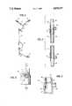
- FIG. 1is a perspective view of a heat exchanger in accordance with the invention in combination with a filter.
- FIG. 2is a longitudinal cross section of the heat exchanger shown in FIG. 1.
- FIG. 3is a side view of an end cap in accordance with the invention.
- FIG. 4is a cross section taken along line 4--4 of FIG. 3.
- a heat exchanger 2 in accordance with the inventionhaving a tube 4 attached to an inlet end, and a tube 6 attached at an outlet end.
- Tube 4is connected through a Y-connector to bag spikes 8.
- Each of the tubesmay have a flow controller 10 thereon for deforming the tubes to control the liquid flow.
- a filter and air eliminator 12is connected to heat exchanger 2 by tube 6, and a tube 14 extends from the outlet of filter 12 to a connector 16 for passing a physiological fluid to a patient.
- Spikes 8are designed to be connected to bags, which are known in the art, containing a physiological fluid, such as blood, to be administered to a patient.
- FIG. 2is a longitudinal cross section of the heat exchanger shown in FIG. 1.
- the heat exchangercomprises an outer conduit 18 which partially surrounds an inner conduit 20.
- the outer conduitis spaced from the inner conduit to provide a flow channel 22, which in the preferred embodiment is a helical path.
- Outer conduit 18is sealed and secured to inner conduit 20 at opposite ends by end caps 24 and 26, which are preferably identical.
- End cap 24includes a tubing connector 28, and end cap 26 includes a similar tubing connector 30.
- Inner conduit 20extends beyond end caps 24 and 26 to provide a first connecting projection 32 and a second connecting projection 34.
- connecting projections 32 and 34engage connecting blocks of a fluid supply system whereby a warming fluid is supplied to the inner conduit 20.
- sections of flexible tubingare connected to tubing connectors 28 and 30 for supplying a physiological fluid to flow channel 22.
- Inner tube 20is made of a bio-compatible metal which is preferably aluminum and may be anodized or otherwise coated.
- Inner conduit 20functions as a heat conductor, conducting heat from the warming fluid passing through the inner conduit to the fluid to be warmed which flows through flow channel 22.
- Inner conduit 20preferably has a wall thickness of 0.016 inches and may be in the range of from 0.014 inches to 0.025 inches.
- the outer diameteris preferably 0.5 inches and may be 0.498 inches to 0.502 inches.
- the exchangerAs the warming fluid is applied to the heat exchanger, the exchanger itself will become warm.
- the interior tube, being of metalwill necessarily expand as it is warmed and contract as it cools after use.
- outer conduit 18is fabricated of a bio-compatible elastomeric plastic which expands or contracts along with the inner conduit.
- the outer conduitis made of polyvinylchloride and has a wall thickness of 0.060 inches. The wall thickness may be from 0.050 to 0.070 inches.
- the outer diameteris preferably 0.63 inches but may be from 0.62 to 0.64 inches, while the inner diameter is preferably 0.51 inches and may be from 0.502 inches to 0.520 inches.
- End caps 24 and 26overlap respective end portions of outer conduit 18 and are secured to the outer conduit by a solvent cement.
- the end capsare also made of bio-compatible elastomeric plastic and also accommodate some of the expansion of the inner conduit 20.
- the materials from which the outer tube and end caps are fabricatedalso provide these elements with heat insulating capability to increase the efficiency of the heat exchanger.
- the inner tubeis fabricated with a helical path by a twisting operation which forms no part of this application.
- Other techniques for increasing the surface area of the inner conduitare known to the art.
- the outer surface of the inner tubeis smooth.
- a first portion 36is hollow and provides an inner wall 38 for engaging the outer surface of outer conduit 22 and for being solvent bonded thereto.
- a second portion 40is also hollow and receives a smooth-wall portion of inner conduit 20.
- the second portion 40includes an inner wall 42 for tightly engaging the outer surface of inner conduit 20.
- the second portionfurther includes a protuberance in the form of an annular ring 44.
- This annular ringconcentrates the stress on the rigid inner conduit 20 to increase the hoop strength of the second portion of the end cap. This increases the sealing strength of the assembly.
- the interior diameter of wall 38is preferably approximately 0.625 inches before assembly with outer conduit 18 to provide a tight connection.
- Inner wall 42has a diameter of approximately 0.460 inches before assembly, and protuberance 44 extends radially inwardly from wall 42 by approximately 0.015 inches.
- protuberance 44is approximately 0.030 inches smaller than that of inner wall 42.
- Protuberance 44is preferably rounded in cross-section with a radius of approximately 0.03 inches.
- second portion 40causes second portion 40 to tightly grip the outer surface of inner conduit 20 without the necessity of using a cement.
- the end caps and outer conduit 18expand also because of the elasticity of the materials used for their construction. Sterility is maintained because the section 40 tightly grips inner conduit 20 and remains stationary with respect to the inner conduit during expansion or contraction.
- the inner and outer conduitsare cylindrical and the inner walls 38 and 42 of the end caps are also cylindrical. This provides an equal distribution of pressures around the seal areas. If the heat exchanger is to be used in an environment of extreme pressures in flow channel 22, it may be desired to provide a band around the outside of second portion 40 of the end cap.
Landscapes
- Engineering & Computer Science (AREA)
- Physics & Mathematics (AREA)
- Thermal Sciences (AREA)
- Mechanical Engineering (AREA)
- General Engineering & Computer Science (AREA)
- Health & Medical Sciences (AREA)
- Biomedical Technology (AREA)
- Anesthesiology (AREA)
- Vascular Medicine (AREA)
- Heart & Thoracic Surgery (AREA)
- Hematology (AREA)
- Life Sciences & Earth Sciences (AREA)
- Animal Behavior & Ethology (AREA)
- General Health & Medical Sciences (AREA)
- Public Health (AREA)
- Veterinary Medicine (AREA)
- Heat-Exchange Devices With Radiators And Conduit Assemblies (AREA)
Abstract
Description
Claims (13)
Priority Applications (1)
| Application Number | Priority Date | Filing Date | Title |
|---|---|---|---|
| US07/053,637US4878537A (en) | 1986-05-27 | 1987-05-26 | Heat exchanger for physiological fluids |
Applications Claiming Priority (2)
| Application Number | Priority Date | Filing Date | Title |
|---|---|---|---|
| US06/866,910US4759749A (en) | 1986-05-27 | 1986-05-27 | Heater for physiological fluids |
| US07/053,637US4878537A (en) | 1986-05-27 | 1987-05-26 | Heat exchanger for physiological fluids |
Related Parent Applications (1)
| Application Number | Title | Priority Date | Filing Date |
|---|---|---|---|
| US06/866,910Continuation-In-PartUS4759749A (en) | 1986-05-27 | 1986-05-27 | Heater for physiological fluids |
Publications (1)
| Publication Number | Publication Date |
|---|---|
| US4878537Atrue US4878537A (en) | 1989-11-07 |
Family
ID=26732079
Family Applications (1)
| Application Number | Title | Priority Date | Filing Date |
|---|---|---|---|
| US07/053,637Expired - LifetimeUS4878537A (en) | 1986-05-27 | 1987-05-26 | Heat exchanger for physiological fluids |
Country Status (1)
| Country | Link |
|---|---|
| US (1) | US4878537A (en) |
Cited By (44)
| Publication number | Priority date | Publication date | Assignee | Title |
|---|---|---|---|---|
| US5245693A (en)* | 1991-03-15 | 1993-09-14 | In-Touch Products Co. | Parenteral fluid warmer apparatus and disposable cassette utilizing thin, flexible heat-exchange membrane |
| US5254094A (en)* | 1989-07-17 | 1993-10-19 | Starkey David L | Physiological fluid warmer |
| US5269749A (en)* | 1992-05-08 | 1993-12-14 | Cobe Laboratories, Inc. | Heat exchange device for inducing cardioplegia |
| US5381510A (en)* | 1991-03-15 | 1995-01-10 | In-Touch Products Co. | In-line fluid heating apparatus with gradation of heat energy from inlet to outlet |
| US5403281A (en)* | 1992-09-25 | 1995-04-04 | Minnesota Mining And Manufacturing Company | Inline heat exchanger and cardioplegia system |
| US5514095A (en)* | 1994-04-04 | 1996-05-07 | Haemonetics Corporation | Apparatus for heating, filtering and eliminating gas from biological fluids |
| US5807332A (en)* | 1994-03-22 | 1998-09-15 | Augustine Medical, Inc. | Tube apparatus for warming intravenous fluids within an air hose |
| US5817146A (en)* | 1995-11-09 | 1998-10-06 | Augustine Medical, Inc. | Patient warming system with IV fluid warmer |
| US5846224A (en)* | 1996-10-01 | 1998-12-08 | Baxter International Inc. | Container for use with blood warming apparatus |
| US6047108A (en)* | 1996-10-01 | 2000-04-04 | Baxter International Inc. | Blood warming apparatus |
| US6175688B1 (en) | 1998-07-10 | 2001-01-16 | Belmont Instrument Corporation | Wearable intravenous fluid heater |
| US6229957B1 (en) | 1999-05-14 | 2001-05-08 | Joseph Baker | Physiological fluid warming process and apparatus |
| US6467953B1 (en) | 1999-03-30 | 2002-10-22 | Medical Solutions, Inc. | Method and apparatus for monitoring temperature of intravenously delivered fluids and other medical items |
| EP1238571A4 (en)* | 1999-10-26 | 2003-03-26 | Level 1 Inc | APPARATUS FOR CONTROLLING THE TEMPERATURE OF A FLUID |
| US6824528B1 (en) | 1997-03-03 | 2004-11-30 | Medical Solutions, Inc. | Method and apparatus for pressure infusion and temperature control of infused liquids |
| WO2005009500A3 (en)* | 2003-07-09 | 2005-08-25 | Enginivity Llc | Medical fluid warming system |
| US20060001794A1 (en)* | 1997-04-11 | 2006-01-05 | Klein Dean A | Assemblies and methods for illuminating a display |
| US20060009736A1 (en)* | 2004-07-07 | 2006-01-12 | Brijesh Gill | Portable fluid warming system |
| US7041941B2 (en) | 1997-04-07 | 2006-05-09 | Patented Medical Solutions, Llc | Medical item thermal treatment systems and method of monitoring medical items for compliance with prescribed requirements |
| US7090658B2 (en) | 1997-03-03 | 2006-08-15 | Medical Solutions, Inc. | Temperature sensing device for selectively measuring temperature at desired locations along an intravenous fluid line |
| US20070007277A1 (en)* | 2003-08-28 | 2007-01-11 | Joa Bosco Correa Bittencourt | Device with heating and temperature monitoring system of fluid in single and multiple container sets for parentheral solutions |
| US20070106243A1 (en)* | 2005-10-27 | 2007-05-10 | Faries Durward I Jr | Method and apparatus to indicate prior use of a medical item |
| US7236694B1 (en) | 2006-01-27 | 2007-06-26 | Jacques Chammas | Blood and biological fluid warmer |
| US7276046B1 (en) | 2002-11-18 | 2007-10-02 | Biosynergy, Inc. | Liquid conductive cooling/heating device and method of use |
| US7276675B2 (en) | 1997-04-07 | 2007-10-02 | Patented Medical Solutions, Llc | Medical item thermal treatment systems and method of monitoring medical items for compliance with prescribed requirements |
| US20080021393A1 (en)* | 2004-07-07 | 2008-01-24 | Brijesh Gill | Portable Fluid Warming System |
| US20090159248A1 (en)* | 2007-12-21 | 2009-06-25 | Mimitz Sr Timothy E | Heat exchanger, heat exchanger tube and methods of making and using same |
| US7611504B1 (en) | 2004-03-09 | 2009-11-03 | Patented Medical Solutions Llc | Method and apparatus for facilitating injection of medication into an intravenous fluid line while maintaining sterility of infused fluids |
| US20100006263A1 (en)* | 2008-07-11 | 2010-01-14 | Smiths Medical Asd, Inc. | Multi lumen heat exchanger |
| US20120043055A1 (en)* | 2010-08-18 | 2012-02-23 | Halla Climate Control Corp. | Double Pipe Type Heat Exchanger and Method for Manufacturing the Same |
| US8226605B2 (en) | 2001-12-17 | 2012-07-24 | Medical Solutions, Inc. | Method and apparatus for heating solutions within intravenous lines to desired temperatures during infusion |
| US8226293B2 (en) | 2007-02-22 | 2012-07-24 | Medical Solutions, Inc. | Method and apparatus for measurement and control of temperature for infused liquids |
| US9119912B2 (en) | 2001-03-12 | 2015-09-01 | Medical Solutions, Inc. | Method and apparatus for controlling pressurized infusion and temperature of infused liquids |
| US9211381B2 (en) | 2012-01-20 | 2015-12-15 | Medical Solutions, Inc. | Method and apparatus for controlling temperature of medical liquids |
| DE102005063620B3 (en)* | 2004-11-09 | 2017-03-09 | Denso Corporation | Double walled pipe |
| US9656029B2 (en) | 2013-02-15 | 2017-05-23 | Medical Solutions, Inc. | Plural medical item warming system and method for warming a plurality of medical items to desired temperatures |
| US9737672B2 (en) | 2007-08-07 | 2017-08-22 | Belmont Instrument Corporation | Hyperthermia, system, method, and components |
| US10137257B2 (en) | 2016-11-30 | 2018-11-27 | Belmont Instrument, Llc | Slack-time heating system for blood and fluid warming |
| US10363381B2 (en) | 2013-01-31 | 2019-07-30 | Smiths Medical International Limited | Medical infusion fluid heat exchange apparatus and warming systems |
| US10465831B2 (en)* | 2014-08-12 | 2019-11-05 | Norma Germany Gmbh | Fluid line |
| US10485936B2 (en) | 2016-11-30 | 2019-11-26 | Belmont Instrument, Llc | Rapid infuser with advantageous flow path for blood and fluid warming |
| US10507292B2 (en) | 2016-11-30 | 2019-12-17 | Belmont Instrument, Llc | Rapid infuser with vacuum release valve |
| US11000407B2 (en) | 2007-08-07 | 2021-05-11 | Belmont Instrument, Llc | Hyperthermia, system, method, and components |
| JP2021105419A (en)* | 2019-12-26 | 2021-07-26 | 株式会社前川製作所 | Bi-metal pipe, heat insulation pipe and refrigeration system |
Citations (5)
| Publication number | Priority date | Publication date | Assignee | Title |
|---|---|---|---|---|
| US2316376A (en)* | 1941-04-28 | 1943-04-13 | Weiss Louis | Chilling means for draft beverages |
| US3893507A (en)* | 1971-12-02 | 1975-07-08 | Calmac Mfg Corp | Apparatus for creating and maintaining an ice slab |
| US4231425A (en)* | 1978-02-27 | 1980-11-04 | Engstrom William R | Extracorporeal circuit blood heat exchanger |
| US4231353A (en)* | 1977-05-13 | 1980-11-04 | Sanyo Electric Co., Ltd. | Solar heat collecting apparatus |
| US4475584A (en)* | 1980-10-10 | 1984-10-09 | Suddeutsche Kuhlerfabrik Julius Fr. Behr Gmbh & Co. Kg | Double-tube radiator |
- 1987
- 1987-05-26USUS07/053,637patent/US4878537A/ennot_activeExpired - Lifetime
Patent Citations (5)
| Publication number | Priority date | Publication date | Assignee | Title |
|---|---|---|---|---|
| US2316376A (en)* | 1941-04-28 | 1943-04-13 | Weiss Louis | Chilling means for draft beverages |
| US3893507A (en)* | 1971-12-02 | 1975-07-08 | Calmac Mfg Corp | Apparatus for creating and maintaining an ice slab |
| US4231353A (en)* | 1977-05-13 | 1980-11-04 | Sanyo Electric Co., Ltd. | Solar heat collecting apparatus |
| US4231425A (en)* | 1978-02-27 | 1980-11-04 | Engstrom William R | Extracorporeal circuit blood heat exchanger |
| US4475584A (en)* | 1980-10-10 | 1984-10-09 | Suddeutsche Kuhlerfabrik Julius Fr. Behr Gmbh & Co. Kg | Double-tube radiator |
Cited By (79)
| Publication number | Priority date | Publication date | Assignee | Title |
|---|---|---|---|---|
| US5254094A (en)* | 1989-07-17 | 1993-10-19 | Starkey David L | Physiological fluid warmer |
| US5245693A (en)* | 1991-03-15 | 1993-09-14 | In-Touch Products Co. | Parenteral fluid warmer apparatus and disposable cassette utilizing thin, flexible heat-exchange membrane |
| US5381510A (en)* | 1991-03-15 | 1995-01-10 | In-Touch Products Co. | In-line fluid heating apparatus with gradation of heat energy from inlet to outlet |
| US5269749A (en)* | 1992-05-08 | 1993-12-14 | Cobe Laboratories, Inc. | Heat exchange device for inducing cardioplegia |
| US5403281A (en)* | 1992-09-25 | 1995-04-04 | Minnesota Mining And Manufacturing Company | Inline heat exchanger and cardioplegia system |
| US5807332A (en)* | 1994-03-22 | 1998-09-15 | Augustine Medical, Inc. | Tube apparatus for warming intravenous fluids within an air hose |
| US5514095A (en)* | 1994-04-04 | 1996-05-07 | Haemonetics Corporation | Apparatus for heating, filtering and eliminating gas from biological fluids |
| US5817146A (en)* | 1995-11-09 | 1998-10-06 | Augustine Medical, Inc. | Patient warming system with IV fluid warmer |
| US5846224A (en)* | 1996-10-01 | 1998-12-08 | Baxter International Inc. | Container for use with blood warming apparatus |
| US6047108A (en)* | 1996-10-01 | 2000-04-04 | Baxter International Inc. | Blood warming apparatus |
| US8920387B2 (en) | 1997-03-03 | 2014-12-30 | Medical Solutions, Inc. | Method and apparatus for pressure infusion and temperature control of infused liquids |
| US8313462B2 (en) | 1997-03-03 | 2012-11-20 | Medical Solutions, Inc. | Method and apparatus for pressure infusion and temperature control of infused liquids |
| US7090658B2 (en) | 1997-03-03 | 2006-08-15 | Medical Solutions, Inc. | Temperature sensing device for selectively measuring temperature at desired locations along an intravenous fluid line |
| US7540864B2 (en) | 1997-03-03 | 2009-06-02 | Medical Solutions, Inc. | Temperature sensing device for selectively measuring temperature at desired locations along an intravenous fluid line |
| US6824528B1 (en) | 1997-03-03 | 2004-11-30 | Medical Solutions, Inc. | Method and apparatus for pressure infusion and temperature control of infused liquids |
| US7942851B2 (en) | 1997-03-03 | 2011-05-17 | Medical Solutions, Inc. | Method and apparatus for pressure infusion and temperature control of infused liquids |
| US7417205B2 (en) | 1997-04-07 | 2008-08-26 | Patented Medical Solutions, Llc | Medical item thermal treatment systems and method of monitoring medical items for compliance with prescribed requirements |
| US7307245B2 (en) | 1997-04-07 | 2007-12-11 | Patented Medical Solutions, Llc | Medical item thermal treatment systems and method of monitoring medical items for compliance with prescribed requirements |
| US7276675B2 (en) | 1997-04-07 | 2007-10-02 | Patented Medical Solutions, Llc | Medical item thermal treatment systems and method of monitoring medical items for compliance with prescribed requirements |
| US7041941B2 (en) | 1997-04-07 | 2006-05-09 | Patented Medical Solutions, Llc | Medical item thermal treatment systems and method of monitoring medical items for compliance with prescribed requirements |
| US20060001794A1 (en)* | 1997-04-11 | 2006-01-05 | Klein Dean A | Assemblies and methods for illuminating a display |
| US20100066940A1 (en)* | 1997-04-11 | 2010-03-18 | Micron Technology, Inc. | Assemblies and methods for illuminating a display |
| US20070008453A1 (en)* | 1997-04-11 | 2007-01-11 | Klein Dean A | Assemblies and methods for illuminating a display |
| US6175688B1 (en) | 1998-07-10 | 2001-01-16 | Belmont Instrument Corporation | Wearable intravenous fluid heater |
| US6480257B2 (en) | 1998-07-10 | 2002-11-12 | Belmont Instrument Corporation | Heat exchanger useable in wearable fluid heater |
| US6236809B1 (en) | 1998-07-10 | 2001-05-22 | Belmont Instrument Corporation | Wearable intravenous fluid heater |
| US6566631B2 (en) | 1999-03-30 | 2003-05-20 | Medical Solutions, Inc. | Method and apparatus for monitoring temperature of intravenously delivered fluids and other medical items |
| US8821011B2 (en) | 1999-03-30 | 2014-09-02 | Medical Solutions, Inc. | Method and apparatus for monitoring temperature of intravenously delivered fluids and other medical items |
| US6722782B2 (en) | 1999-03-30 | 2004-04-20 | Medical Solutions, Inc. | Method and apparatus for monitoring temperature of intravenously delivered fluids and other medical items |
| US6467953B1 (en) | 1999-03-30 | 2002-10-22 | Medical Solutions, Inc. | Method and apparatus for monitoring temperature of intravenously delivered fluids and other medical items |
| US6229957B1 (en) | 1999-05-14 | 2001-05-08 | Joseph Baker | Physiological fluid warming process and apparatus |
| EP1238571A4 (en)* | 1999-10-26 | 2003-03-26 | Level 1 Inc | APPARATUS FOR CONTROLLING THE TEMPERATURE OF A FLUID |
| US9119912B2 (en) | 2001-03-12 | 2015-09-01 | Medical Solutions, Inc. | Method and apparatus for controlling pressurized infusion and temperature of infused liquids |
| US8920372B2 (en) | 2001-12-17 | 2014-12-30 | Medical Solutions, Inc. | Method and apparatus for heating solutions within intravenous lines to desired temperatures during infusion |
| US8226605B2 (en) | 2001-12-17 | 2012-07-24 | Medical Solutions, Inc. | Method and apparatus for heating solutions within intravenous lines to desired temperatures during infusion |
| US9492624B2 (en) | 2001-12-17 | 2016-11-15 | Medical Solutions, Inc. | Method and apparatus for heating solutions within intravenous lines to desired temperatures during infusion |
| US7276046B1 (en) | 2002-11-18 | 2007-10-02 | Biosynergy, Inc. | Liquid conductive cooling/heating device and method of use |
| WO2005009500A3 (en)* | 2003-07-09 | 2005-08-25 | Enginivity Llc | Medical fluid warming system |
| US7158719B2 (en) | 2003-07-09 | 2007-01-02 | Enginivity Llc | Medical fluid warming system |
| US8965186B2 (en)* | 2003-08-28 | 2015-02-24 | João Bosco Corrêa Bittencourt | Device with heating and temperature monitoring system of fluid in single and multiple container sets for parentheral solutions |
| US20070007277A1 (en)* | 2003-08-28 | 2007-01-11 | Joa Bosco Correa Bittencourt | Device with heating and temperature monitoring system of fluid in single and multiple container sets for parentheral solutions |
| US7611504B1 (en) | 2004-03-09 | 2009-11-03 | Patented Medical Solutions Llc | Method and apparatus for facilitating injection of medication into an intravenous fluid line while maintaining sterility of infused fluids |
| US8845586B2 (en) | 2004-03-09 | 2014-09-30 | Patented Medical Solutions Llc | Method and apparatus for facilitating injection of medication into an intravenous fluid line while maintaining sterility of infused fluids |
| US20110184501A1 (en)* | 2004-07-07 | 2011-07-28 | Brijesh Gill | Portable Fluid Warming System |
| US20080021393A1 (en)* | 2004-07-07 | 2008-01-24 | Brijesh Gill | Portable Fluid Warming System |
| US7891974B2 (en) | 2004-07-07 | 2011-02-22 | The Board Of Regents Of The University Of Texas System | Portable fluid warming system |
| US20060009736A1 (en)* | 2004-07-07 | 2006-01-12 | Brijesh Gill | Portable fluid warming system |
| US7261557B2 (en) | 2004-07-07 | 2007-08-28 | The Board Of Regents Of The University Of Texas System | Portable fluid warming system |
| US8753382B2 (en) | 2004-07-07 | 2014-06-17 | The Board Of Regents Of The University Of Texas Systems | Portable fluid warming system |
| DE102005063620B3 (en)* | 2004-11-09 | 2017-03-09 | Denso Corporation | Double walled pipe |
| US9669499B2 (en) | 2004-11-09 | 2017-06-06 | Denso Corporation | Double-wall pipe, method of manufacturing the same and refrigerant cycle device provided with the same |
| US7740611B2 (en) | 2005-10-27 | 2010-06-22 | Patented Medical Solutions, Llc | Method and apparatus to indicate prior use of a medical item |
| US20070106243A1 (en)* | 2005-10-27 | 2007-05-10 | Faries Durward I Jr | Method and apparatus to indicate prior use of a medical item |
| US8444599B2 (en) | 2005-10-27 | 2013-05-21 | Patented Medical Solutions, Llc | Method and apparatus to indicate prior use of a medical item |
| US8636691B2 (en) | 2005-10-27 | 2014-01-28 | Patented Medical Solutions, Llc | Method and apparatus to indicate prior use of a medical item |
| US7236694B1 (en) | 2006-01-27 | 2007-06-26 | Jacques Chammas | Blood and biological fluid warmer |
| US8226293B2 (en) | 2007-02-22 | 2012-07-24 | Medical Solutions, Inc. | Method and apparatus for measurement and control of temperature for infused liquids |
| WO2009018025A1 (en)* | 2007-08-01 | 2009-02-05 | The Board Of Regents Of The University Of Texas System | Portable fluid warming system |
| US9737672B2 (en) | 2007-08-07 | 2017-08-22 | Belmont Instrument Corporation | Hyperthermia, system, method, and components |
| US11000407B2 (en) | 2007-08-07 | 2021-05-11 | Belmont Instrument, Llc | Hyperthermia, system, method, and components |
| US20090159248A1 (en)* | 2007-12-21 | 2009-06-25 | Mimitz Sr Timothy E | Heat exchanger, heat exchanger tube and methods of making and using same |
| US8613723B2 (en) | 2008-07-11 | 2013-12-24 | Smiths Medical Asd, Inc. | Multi lumen heat exchanger |
| US20100006263A1 (en)* | 2008-07-11 | 2010-01-14 | Smiths Medical Asd, Inc. | Multi lumen heat exchanger |
| WO2010005537A3 (en)* | 2008-07-11 | 2010-03-25 | Smiths Medical Asd, Inc. | Multi lumen heat exchanger |
| CN102149353B (en)* | 2008-07-11 | 2013-06-19 | 史密斯医疗Asd公司 | multi-chamber heat exchanger |
| US9091487B2 (en)* | 2010-08-18 | 2015-07-28 | Halla Visteon Climate Control Corporation | Double pipe type heat exchanger and method for manufacturing the same |
| US20150224561A1 (en)* | 2010-08-18 | 2015-08-13 | Halla Visteon Climate Control Corp. | Double pipe type heat exchanger and method for manufacturing the same |
| US9821364B2 (en)* | 2010-08-18 | 2017-11-21 | Hanon Systems | Double pipe type heat exchanger and method for manufacturing the same |
| US20120043055A1 (en)* | 2010-08-18 | 2012-02-23 | Halla Climate Control Corp. | Double Pipe Type Heat Exchanger and Method for Manufacturing the Same |
| US9211381B2 (en) | 2012-01-20 | 2015-12-15 | Medical Solutions, Inc. | Method and apparatus for controlling temperature of medical liquids |
| US9764100B2 (en) | 2012-01-20 | 2017-09-19 | Medical Solutions, Inc. | Method and apparatus for controlling temperature of medical liquids |
| US10363381B2 (en) | 2013-01-31 | 2019-07-30 | Smiths Medical International Limited | Medical infusion fluid heat exchange apparatus and warming systems |
| US9656029B2 (en) | 2013-02-15 | 2017-05-23 | Medical Solutions, Inc. | Plural medical item warming system and method for warming a plurality of medical items to desired temperatures |
| US10465831B2 (en)* | 2014-08-12 | 2019-11-05 | Norma Germany Gmbh | Fluid line |
| US10485936B2 (en) | 2016-11-30 | 2019-11-26 | Belmont Instrument, Llc | Rapid infuser with advantageous flow path for blood and fluid warming |
| US10507292B2 (en) | 2016-11-30 | 2019-12-17 | Belmont Instrument, Llc | Rapid infuser with vacuum release valve |
| US10137257B2 (en) | 2016-11-30 | 2018-11-27 | Belmont Instrument, Llc | Slack-time heating system for blood and fluid warming |
| US11872382B2 (en) | 2016-11-30 | 2024-01-16 | Belmont Instrument, Llc | Rapid infuser with advantageous flow path for blood and fluid warming, and associated components, systems, and methods |
| JP2021105419A (en)* | 2019-12-26 | 2021-07-26 | 株式会社前川製作所 | Bi-metal pipe, heat insulation pipe and refrigeration system |
Similar Documents
| Publication | Publication Date | Title |
|---|---|---|
| US4878537A (en) | Heat exchanger for physiological fluids | |
| JP3110798B2 (en) | Backflow type heated fluid patient supply device | |
| US5601894A (en) | Insulated intravenous administration tubing and drip chambers | |
| US4588402A (en) | Connector for medical tubing and medical solution bag device using the connector | |
| US5864938A (en) | Assembly of semi-disposable ventilator breathing circuit tubing with releasable coupling | |
| US4657743A (en) | Heat exchanger-incorporated hollow fiber type artifical lung | |
| US4645645A (en) | Oxygenator having an improved heat exchanger | |
| US4649959A (en) | Antiburst system for water lines | |
| JPH02185226A (en) | Flexible inserting-tube | |
| US6074363A (en) | Intravenous fluid heat exchanger | |
| US6621985B1 (en) | Electric water heater | |
| US4425936A (en) | Concentric tube heat tracing apparatus | |
| US5100549A (en) | Tubular membrane module | |
| EP0280448B1 (en) | Fluid container port connector mounting | |
| US20230201745A1 (en) | Tube unit, degassing module, and method of manufacturing tube unit | |
| JPS62258677A (en) | Heating and cooling apparatus and its production | |
| US5770139A (en) | Method and apparatus for connecting tubing to barbed connectors | |
| EP0309710A1 (en) | Heating arrangement | |
| EP0256653A2 (en) | Blood compatible heat exchanger | |
| US6234542B1 (en) | Expansion joint for a fluid piping system | |
| EP0009911B1 (en) | Flush valve | |
| JPS63280967A (en) | Manufacture of fluorine resin covered rubber o-ring | |
| KR101856758B1 (en) | A manhole connector with heat sink tube | |
| CN210301870U (en) | A simple device suitable for temperature regulation of circulating pipeline | |
| IE820218L (en) | Heat exchanger |
Legal Events
| Date | Code | Title | Description |
|---|---|---|---|
| AS | Assignment | Owner name:LEVEL 1 TECHNOLOGIES, INC., 29 ALDRIN ROAD, PLYMOU Free format text:ASSIGNMENT OF ASSIGNORS INTEREST.;ASSIGNOR:VERKAART, WESLEY H.;REEL/FRAME:004895/0876 Effective date:19870522 | |
| STCF | Information on status: patent grant | Free format text:PATENTED CASE | |
| FPAY | Fee payment | Year of fee payment:4 | |
| AS | Assignment | Owner name:SIMS LEVEL 1, INC., MASSACHUSETTS Free format text:CHANGE OF NAME;ASSIGNOR:LEVEL 1 TECHNOLOGIES, INC.;REEL/FRAME:007969/0136 Effective date:19951017 | |
| FEPP | Fee payment procedure | Free format text:PAT HLDR NO LONGER CLAIMS SMALL ENT STAT AS SMALL BUSINESS (ORIGINAL EVENT CODE: LSM2); ENTITY STATUS OF PATENT OWNER: LARGE ENTITY Free format text:PAYOR NUMBER ASSIGNED (ORIGINAL EVENT CODE: ASPN); ENTITY STATUS OF PATENT OWNER: LARGE ENTITY | |
| FPAY | Fee payment | Year of fee payment:8 | |
| FPAY | Fee payment | Year of fee payment:12 | |
| AS | Assignment | Owner name:LEVEL 1, INC., MASSACHUSETTS Free format text:CHANGE OF NAME;ASSIGNOR:SIMS LEVEL 1, INC.;REEL/FRAME:012495/0284 Effective date:20010701 | |
| AS | Assignment | Owner name:SMITHS MEDICAL ASD, INC., NEW HAMPSHIRE Free format text:CHANGE OF NAME;ASSIGNOR:LEVEL 1, INC.;REEL/FRAME:015044/0700 Effective date:20031222 |