US4877193A - Redirect roller apparatus for fiber placement machine - Google Patents
Redirect roller apparatus for fiber placement machineDownload PDFInfo
- Publication number
- US4877193A US4877193AUS07/236,417US23641788AUS4877193AUS 4877193 AUS4877193 AUS 4877193AUS 23641788 AUS23641788 AUS 23641788AUS 4877193 AUS4877193 AUS 4877193A
- Authority
- US
- United States
- Prior art keywords
- fiber
- roller
- band
- redirect
- fibers
- Prior art date
- Legal status (The legal status is an assumption and is not a legal conclusion. Google has not performed a legal analysis and makes no representation as to the accuracy of the status listed.)
- Expired - Lifetime
Links
- 239000000835fiberSubstances0.000titleclaimsabstractdescription66
- 210000000707wristAnatomy0.000claimsabstractdescription17
- 210000000245forearmAnatomy0.000description7
- 230000000712assemblyEffects0.000description2
- 238000000429assemblyMethods0.000description2
- 239000012636effectorSubstances0.000description2
- 238000009730filament windingMethods0.000description2
- 239000011888foilSubstances0.000description2
- 230000007246mechanismEffects0.000description2
- 238000004804windingMethods0.000description2
- 239000002131composite materialSubstances0.000description1
- 150000001875compoundsChemical class0.000description1
- 230000006835compressionEffects0.000description1
- 238000007906compressionMethods0.000description1
- 230000000694effectsEffects0.000description1
- 238000004519manufacturing processMethods0.000description1
- 125000006850spacer groupChemical group0.000description1
Images


Classifications
- B—PERFORMING OPERATIONS; TRANSPORTING
- B29—WORKING OF PLASTICS; WORKING OF SUBSTANCES IN A PLASTIC STATE IN GENERAL
- B29C—SHAPING OR JOINING OF PLASTICS; SHAPING OF MATERIAL IN A PLASTIC STATE, NOT OTHERWISE PROVIDED FOR; AFTER-TREATMENT OF THE SHAPED PRODUCTS, e.g. REPAIRING
- B29C70/00—Shaping composites, i.e. plastics material comprising reinforcements, fillers or preformed parts, e.g. inserts
- B29C70/04—Shaping composites, i.e. plastics material comprising reinforcements, fillers or preformed parts, e.g. inserts comprising reinforcements only, e.g. self-reinforcing plastics
- B29C70/28—Shaping operations therefor
- B29C70/30—Shaping by lay-up, i.e. applying fibres, tape or broadsheet on a mould, former or core; Shaping by spray-up, i.e. spraying of fibres on a mould, former or core
- B29C70/32—Shaping by lay-up, i.e. applying fibres, tape or broadsheet on a mould, former or core; Shaping by spray-up, i.e. spraying of fibres on a mould, former or core on a rotating mould, former or core
- B—PERFORMING OPERATIONS; TRANSPORTING
- B29—WORKING OF PLASTICS; WORKING OF SUBSTANCES IN A PLASTIC STATE IN GENERAL
- B29C—SHAPING OR JOINING OF PLASTICS; SHAPING OF MATERIAL IN A PLASTIC STATE, NOT OTHERWISE PROVIDED FOR; AFTER-TREATMENT OF THE SHAPED PRODUCTS, e.g. REPAIRING
- B29C70/00—Shaping composites, i.e. plastics material comprising reinforcements, fillers or preformed parts, e.g. inserts
- B29C70/04—Shaping composites, i.e. plastics material comprising reinforcements, fillers or preformed parts, e.g. inserts comprising reinforcements only, e.g. self-reinforcing plastics
- B29C70/28—Shaping operations therefor
- B29C70/30—Shaping by lay-up, i.e. applying fibres, tape or broadsheet on a mould, former or core; Shaping by spray-up, i.e. spraying of fibres on a mould, former or core
- B29C70/38—Automated lay-up, e.g. using robots, laying filaments according to predetermined patterns
- B29C70/382—Automated fiber placement [AFP]
- B29C70/384—Fiber placement heads, e.g. component parts, details or accessories
- Y—GENERAL TAGGING OF NEW TECHNOLOGICAL DEVELOPMENTS; GENERAL TAGGING OF CROSS-SECTIONAL TECHNOLOGIES SPANNING OVER SEVERAL SECTIONS OF THE IPC; TECHNICAL SUBJECTS COVERED BY FORMER USPC CROSS-REFERENCE ART COLLECTIONS [XRACs] AND DIGESTS
- Y10—TECHNICAL SUBJECTS COVERED BY FORMER USPC
- Y10T—TECHNICAL SUBJECTS COVERED BY FORMER US CLASSIFICATION
- Y10T156/00—Adhesive bonding and miscellaneous chemical manufacture
- Y10T156/17—Surface bonding means and/or assemblymeans with work feeding or handling means
- Y10T156/1788—Work traversing type and/or means applying work to wall or static structure
Definitions
- the inventionrelates to fiber placement machines which may employ multiple strands or tows of fiber which are pulled from a creel assembly and placed on a surface or workpiece.
- Such machinesmay include filament winders, which utilize plural filaments when winding rotary shapes.
- Fiber placement machinesmay also be employed to place tows of fiber on flat, curved, or compound contours.
- Prior art assembliesinclude filament winding machines which deploy plural relatively parallel filaments on a rotary member, where the filaments pass through a payout eye which may be rotated about an axis parallel to the longitudinal path travelled by the filaments to keep the filaments spaced for a variety of winding angles as the paid-out filaments traverse the rotary axis of the member to be wound.
- Applicant's assemblyis directed to a machine which utilizes a creel assembly for supplying filamentous composite material to a laydown surface, where the machine system includes at least a multi-axis manipulator wrist which may orient the laydown tip of the assembly through a wide variety of spatial orientations with respect to the supply creel assembly.
- the inventionis shown embodied in a fiber placement machine having a band of fibers oriented with its length relatively running along a path with respect to a relatively stationary machine member and wherein the band is ultimately paid-out to a fiber application surface, and where the invention is an improved fiber guidance system comprising
- a fiber placement headcarried by the manipulator wrist, and having a fiber payout zone, the head capable through manipulation of variety of spatial orientations, i.e., least two-dimension spatial orientations with respect to the stationary machine member;
- roller baseincludes a bearing member for providing rotary swivel movement of the base about an axis transverse to the roller axis, and wherein at least one direct roller is affixed to the relatively stationary machine member and at least a second redirect roller is affixed to the fiber placement head, and
- a band of fibersis trained around said first and second redirect rollers under tension, and said redirect rollers will swivel about their bases in accordance with spatial orientation of the placement head and in accordance with tension of the fiber band, thereby maintaining approximately equal tension at the outer fibers at each side of the fiber band.
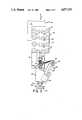
- FIG. 1is a perspective view of a fiber placement machine.
- FIG. 2is an elevational view showing the vertical forearm of the fiber placement machine of FIG. 1 supporting a fiber placement head.
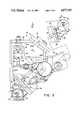
- FIG. 3is a close-up elevational view of the fiber placement head of FIG. 2.
- FIG. 4is a section through a redirect roller.
- FIG. 5is a plan view of the fiber placement head.
- FIG. 6is a diagrammatic view of the redirect roller pair.
- FIG. 1shows a gantry machine or robot 10 having an elevated way system suitable for carrying a carriage 11 and cross-slide 12 in X and Y directions, in a plane parallel to the floor.
- the cross-slide 12supports a saddle 13 for vertical movement, and the saddle 13 has a forearm 14 which contains a drive mechanism (not shown) for actuating a wrist 15 supported at the end of the forearm 14.
- the forearm 14 and wrist 15are manufactured substantially as the serial roll wrist depicted in the U.S. Pat. No. 4,068,536, assigned to Cincinnati Milacron Inc., the assignee of the present invention.
- the gantry robot 10 depicted in FIG. 1is commercially available from Cincinnati Milacron Inc., under the Model No.
- the wrist 15has the capability of moving a tooling plate 16 in three degrees of rotary motion, and a desired tool assembly, or end effector (not shown), is affixed to the tooling plate 16. It will be appreciated that other wrists, for example, the roll-bend-roll variety of manipulators, may be employed.
- a variety of workmay be positioned on the floor within the range of the tooling plate 16.
- the workmay be flat or curved; rotating or stationary.
- a servo-controlled mandrel unit 17is shown, having a rotary spindle 18 for positioning an exemplary workpiece, such as an air foil form 19.
- the mandrel unit 17is, in effect, a headstock capable of supporting, driving, and positioning work about a reference axis 20, here shown horizontally.
- a computer numerical control (CNC) 22is employed to control the multi-degree-of-freedom spatial positioning of the tooling plate 16 and selected end effector.
- the CNC 22also controls the work position about the reference axis 20.
- One such controlis commercially available under the trademark ACRAMATIC--Model 965-C CNC, from Cincinnati Milacron Inc.
- the machine 10is arranged to place long and short lengths of fiber tows 23 on the air foil form 19, for example, in an operation similar to filament winding, but where the tows may extend along concave, or undercut, surfaces.
- FIG. 2schematically depicts the vertical forearm 14 of FIG. 1 with a creel assembly 24 mounted thereto.
- a fiber placement head 25is affixed to the wrist tooling plate 16 and is wieldable to approach the workpiece surface 26, it being appreciated by those skilled in the art that the surface may be curved as well as flat, and the surface 26 may move with respect to the fiber placement head 25 and vice-versa.
- the creel assembly 24 and fiber placement head 25are thus movable on a common forearm 14 and the wrist 15 provides relative movement between the placement head 25 and the creel assembly 24.
- the creel assembly 24is depicted schematically as having eight spools 27 of fiber tows 23, each tow 23 pulled from a spool 27 and trained over a respective tension-maintaining roller 28, in a manner known in the tensioner art, which, basically comprises the use of radially-movable dancer rolls.
- the eight tows 23 depictedare guided around a grooved roller 29 affixed to the forearm 14, and are then trained around a pair of redirect rollers 30 carried on a creel bracket 31 and an outboard support bracket 32 of the placement head 25.
- the creel bracket 31constitutes a relatively-stationary machine member, or base, for referencing movement of the relatively-movable placement head 25 and bracket 32 which are moved by the manipulator wrist 15.
- the redirect rollers 30are mounted in bearings so that they may swivel and thus be automatically oriented in accordance with tension of the fiber tows 23.
- the tows 23are brought through a clamp, cut and restart unit (“CCR" unit) 33 and are finally brought around a presser member assembly 34 where they are impressed on the work surface 26.
- CCRclamp, cut and restart unit
- the fiber placement head 25is shown in more detail, affixed to the tooling plate 16 of the wrist 15.
- the topmost end of the outboard support bracket 32 of the placement head 25is fabricated of a plate 35 having a through clearance hole 36, and the plate 35 supports an antifriction bearing 37 which carries the redirect roller assembly 38.
- the assembly 38is fabricated from a plate 39, having a through clearance hole 40, and welded parallel side plates 41.
- the parallel plates 41captivate the redirect roller 30 which is freely journalled on a tubular support shaft 42 extending through the side plates 41.
- the fiber tows 23are depicted parallel to one another, extending around grooves 30a in the roller 30, and passing down through the open outboard bracket 32 to the CCR unit 33.
- the main bracket 43 of the placement head 25, see FIGS. 3 and 4,is comprised of a fabrication, having a horizontal top plate 44a, angled top corner plate 44b, and a vertical back plate 45, welded with side gussets 46a,b.
- a pilot bore 47is provided through the top corner plate 44b for registration on the wrist tooling plate 16.
- Two pairs of vertically-oriented ball bushings 48are affixed to the vertical plate 45 of the main bracket 43, for guiding a vertical slide 49.
- the slide 49has a pair of precision bars 50 affixed to the rear by suitable support blocks 51, the bars 50 being free to ride vertically in the ball bushings 48.
- the slide 49is configured as a notched plate, having uniform thickness, and the lowermost slide edge 52 carries the presser member assembly 34, which basically comprises a compliant roller, able to adapt to a variety of work-surface contours.
- the grooved redirect guide roller 30is journalled on a tubular pin 53.
- the roller 30is assembled a plurality of spaced single-groove rings 54, i.e. each having a thin annular flange 55 at each side, and the rings 54 are carried by ball bearings 56 on the tubular pin 53 so there will be virtually no drag on the tows 23.
- the tubular pin 53has a head 57 at one end and has a transverse pin 58 captivating a compression spring 59 at the other end.
- the transverse pin 58may be fitted with a ring 60 for ease of disassembly. Spacers 61 at each side of the roller 30 keep the roller centered and free of dragging on the side plates 41.
- the independent anti-friction support of the grooved rings 54permits the fiber tows 23 to move at independent rates across the roller 30 without drag occurring.
- Both roller assemblies 38 shown in FIG. 2are identical, and each have pivot axes 62,63, to permit swivelling of the assembly 38 in accordance with the force components of the tensioned fiber tows 23.
- the axis 64 of the roller and pivot axis of the roller assembly 38are, preferably non-intersecting, to permit a caster-like movement.
Landscapes
- Engineering & Computer Science (AREA)
- Chemical & Material Sciences (AREA)
- Composite Materials (AREA)
- Mechanical Engineering (AREA)
- Robotics (AREA)
- Moulding By Coating Moulds (AREA)
Abstract
Description
Claims (1)
Priority Applications (4)
| Application Number | Priority Date | Filing Date | Title |
|---|---|---|---|
| US07/236,417US4877193A (en) | 1988-08-25 | 1988-08-25 | Redirect roller apparatus for fiber placement machine |
| DE1989609351DE68909351T2 (en) | 1988-08-25 | 1989-06-21 | Laying device for fibers. |
| EP19890111316EP0355308B1 (en) | 1988-08-25 | 1989-06-21 | Fibre placement machine |
| JP1177006AJPH02139467A (en) | 1988-08-25 | 1989-07-07 | Apparatus for guiding fiber |
Applications Claiming Priority (1)
| Application Number | Priority Date | Filing Date | Title |
|---|---|---|---|
| US07/236,417US4877193A (en) | 1988-08-25 | 1988-08-25 | Redirect roller apparatus for fiber placement machine |
Publications (1)
| Publication Number | Publication Date |
|---|---|
| US4877193Atrue US4877193A (en) | 1989-10-31 |
Family
ID=22889413
Family Applications (1)
| Application Number | Title | Priority Date | Filing Date |
|---|---|---|---|
| US07/236,417Expired - LifetimeUS4877193A (en) | 1988-08-25 | 1988-08-25 | Redirect roller apparatus for fiber placement machine |
Country Status (1)
| Country | Link |
|---|---|
| US (1) | US4877193A (en) |
Cited By (34)
| Publication number | Priority date | Publication date | Assignee | Title |
|---|---|---|---|---|
| US5022952A (en)* | 1985-12-13 | 1991-06-11 | Cincinnati Milacron Inc. | Fiber placement machine |
| US5039368A (en)* | 1989-09-25 | 1991-08-13 | Thiokol Corporation | Thermoplastic matrix filament winding head |
| US5063685A (en)* | 1988-09-02 | 1991-11-12 | Renishaw Plc | Tape scale applicator |
| US5110395A (en)* | 1989-12-04 | 1992-05-05 | Cincinnati Milacron Inc. | Fiber placement head |
| WO1992020602A1 (en)* | 1991-05-24 | 1992-11-26 | Cincinnati Milacron Inc. | Intelligent servo-controlled fiber placement machine tensioner |
| US5273614A (en)* | 1991-09-23 | 1993-12-28 | Cincinnati Milacron Inc. | Tow guide for redirect rollers in a fiber placement machine |
| US5290389A (en)* | 1990-12-19 | 1994-03-01 | Hercules Incorporated | Fiber placement delivery system with modular cut/add actuators |
| US5472553A (en)* | 1993-12-30 | 1995-12-05 | The Boeing Company | Filament cutting and placement system |
| US5698066A (en)* | 1990-12-19 | 1997-12-16 | Alliant Techsystems Inc. | Band fiber forming and placement delivery head |
| US5766357A (en)* | 1996-09-19 | 1998-06-16 | Alliant Techsystems Inc. | Apparatus for fiber impregnation |
| US5979531A (en)* | 1997-10-01 | 1999-11-09 | Mcdonnell Douglas Corporation | Bi-directional fiber placement head |
| US6026883A (en)* | 1998-04-30 | 2000-02-22 | Alliant Techsystems, Inc. | Self-contained apparatus for fiber element placement |
| US6050315A (en)* | 1998-04-30 | 2000-04-18 | Alliant Techsystems Inc. | Method and apparatus for producing fiber reinforced structures |
| US6112792A (en)* | 1998-11-19 | 2000-09-05 | The Boeing Company | Fiber placement mid-span redirect |
| US6254027B1 (en)* | 1999-04-28 | 2001-07-03 | Nittoku Engineering Kabushiki Kaisha | Winding machine |
| US6491773B1 (en) | 2000-01-24 | 2002-12-10 | Alliant Techsystems Inc. | Position-controlled tensioner system |
| US6544367B1 (en) | 1999-02-01 | 2003-04-08 | Alliant Techsystems Inc. | Overwrap tape end-effector for fiber placement/winding machines |
| US6752190B1 (en) | 1991-07-31 | 2004-06-22 | Alliant Techsystems Inc. | Cure-on-the-fly system |
| US20050006521A1 (en)* | 2003-05-02 | 2005-01-13 | Harvey James L. | Fiber redirect system, multi-axis robotic wrist and fiber placement apparatus incorporating same and related methods |
| US20060070697A1 (en)* | 2004-09-23 | 2006-04-06 | Ingersoll Machine Tools, Inc. | Method and apparatus for directing resin-impregnated tape |
| NL1028697C2 (en)* | 2005-04-05 | 2006-10-09 | Airborne Dev B V | Device and method for manufacturing fiber-reinforced tube. |
| US20060249256A1 (en)* | 2005-05-03 | 2006-11-09 | Borgmann Robert E | Fiber placement machine |
| US20070226956A1 (en)* | 2006-04-18 | 2007-10-04 | Causey Jeffrey W | Swiveling and tilting roller axis for web guiding in a fiber placement machine |
| US20080302483A1 (en)* | 2007-06-06 | 2008-12-11 | Vaniglia Milo M | Motorized Cut and Feed Head |
| US7785433B2 (en) | 2007-05-31 | 2010-08-31 | The Boeing Company | End effector and methods for constructing composite members |
| US8613302B2 (en) | 2011-03-02 | 2013-12-24 | Fives Machining Systems, Inc. | Reversing fiber placement head |
| US9126374B2 (en) | 2010-09-28 | 2015-09-08 | Russell B. Hanson | Iso-grid composite component |
| US20160031165A1 (en)* | 2014-07-31 | 2016-02-04 | Deutsches Zentrum für Luft- und Raumfahrt e.V. | Fiber-laying device |
| CZ306021B6 (en)* | 2015-04-24 | 2016-06-22 | Magna Exteriors & Interiors (Bohemia) S.R.O. | Device to wrap fiber rovings around the frames |
| US9862135B2 (en) | 2010-06-08 | 2018-01-09 | Airborne International B.V. | Method and device for manufacturing composite products comprising a planar portion |
| US10059067B2 (en) | 2016-01-18 | 2018-08-28 | Fives Machining Systems, Inc. | Small 4-axis fiber placement machine |
| US10144171B2 (en) | 2011-03-03 | 2018-12-04 | AO & G Hollding B.V. | Method for manufacturing continuous composite tube, apparatus for manufacturing continuous composite tube |
| US20200016847A1 (en)* | 2018-07-10 | 2020-01-16 | Bell Helicopter Textron Inc. | Material dispensing systems |
| WO2021156550A1 (en)* | 2020-02-06 | 2021-08-12 | Coriolis Group | Fibre application head with fitted reels |
Citations (6)
| Publication number | Priority date | Publication date | Assignee | Title |
|---|---|---|---|---|
| US1189611A (en)* | 1913-12-18 | 1916-07-04 | Willis S Morse | Guide-roll for webs. |
| US4420121A (en)* | 1981-09-03 | 1983-12-13 | Bausch & Lomb Incorporated | Roll film looping and guiding apparatus |
| US4601775A (en)* | 1985-06-03 | 1986-07-22 | Cincinnati Milacron Inc. | Compliant presser member for composite tape laying machine |
| US4696707A (en)* | 1987-08-18 | 1987-09-29 | The Ingersoll Milling Machine Company | Composite tape placement apparatus with natural path generation means |
| US4699683A (en)* | 1986-02-07 | 1987-10-13 | The Boeing Company | Multiroving fiber laminator |
| US4750965A (en)* | 1986-03-28 | 1988-06-14 | The Ingersoll Milling Machine Company | Adaptive control for tape laying head having natural path generation |
- 1988
- 1988-08-25USUS07/236,417patent/US4877193A/ennot_activeExpired - Lifetime
Patent Citations (6)
| Publication number | Priority date | Publication date | Assignee | Title |
|---|---|---|---|---|
| US1189611A (en)* | 1913-12-18 | 1916-07-04 | Willis S Morse | Guide-roll for webs. |
| US4420121A (en)* | 1981-09-03 | 1983-12-13 | Bausch & Lomb Incorporated | Roll film looping and guiding apparatus |
| US4601775A (en)* | 1985-06-03 | 1986-07-22 | Cincinnati Milacron Inc. | Compliant presser member for composite tape laying machine |
| US4699683A (en)* | 1986-02-07 | 1987-10-13 | The Boeing Company | Multiroving fiber laminator |
| US4750965A (en)* | 1986-03-28 | 1988-06-14 | The Ingersoll Milling Machine Company | Adaptive control for tape laying head having natural path generation |
| US4696707A (en)* | 1987-08-18 | 1987-09-29 | The Ingersoll Milling Machine Company | Composite tape placement apparatus with natural path generation means |
Non-Patent Citations (4)
| Title |
|---|
| "Milacron Today", vol. 4, No. 6, published Jun. 16, 1989, by Cincinnati Milacron Inc., front page article entitled: Fiber Placement: Automating Complex Composite Parts Processing. |
| Fiber Placement Process Study by Don O. Evans, Milo M. Vaniglia and Paul C. Hopkins, published in SAMPE 34th Symposium Book of Proceeding, May 8 11, 1989.* |
| Fiber Placement Process Study by Don O. Evans, Milo M. Vaniglia and Paul C. Hopkins, published in SAMPE 34th Symposium Book of Proceeding, May 8-11, 1989. |
| Milacron Today , vol. 4, No. 6, published Jun. 16, 1989, by Cincinnati Milacron Inc., front page article entitled: Fiber Placement: Automating Complex Composite Parts Processing.* |
Cited By (51)
| Publication number | Priority date | Publication date | Assignee | Title |
|---|---|---|---|---|
| US5022952A (en)* | 1985-12-13 | 1991-06-11 | Cincinnati Milacron Inc. | Fiber placement machine |
| US5063685A (en)* | 1988-09-02 | 1991-11-12 | Renishaw Plc | Tape scale applicator |
| US5039368A (en)* | 1989-09-25 | 1991-08-13 | Thiokol Corporation | Thermoplastic matrix filament winding head |
| US5110395A (en)* | 1989-12-04 | 1992-05-05 | Cincinnati Milacron Inc. | Fiber placement head |
| US5698066A (en)* | 1990-12-19 | 1997-12-16 | Alliant Techsystems Inc. | Band fiber forming and placement delivery head |
| US5290389A (en)* | 1990-12-19 | 1994-03-01 | Hercules Incorporated | Fiber placement delivery system with modular cut/add actuators |
| US5223072A (en)* | 1991-05-24 | 1993-06-29 | Cincinnati Milacron, Inc. | Intelligent servo-controlled fiber placement machine tensioner |
| WO1992020602A1 (en)* | 1991-05-24 | 1992-11-26 | Cincinnati Milacron Inc. | Intelligent servo-controlled fiber placement machine tensioner |
| US6752190B1 (en) | 1991-07-31 | 2004-06-22 | Alliant Techsystems Inc. | Cure-on-the-fly system |
| US5273614A (en)* | 1991-09-23 | 1993-12-28 | Cincinnati Milacron Inc. | Tow guide for redirect rollers in a fiber placement machine |
| US5472553A (en)* | 1993-12-30 | 1995-12-05 | The Boeing Company | Filament cutting and placement system |
| US5766357A (en)* | 1996-09-19 | 1998-06-16 | Alliant Techsystems Inc. | Apparatus for fiber impregnation |
| US5979531A (en)* | 1997-10-01 | 1999-11-09 | Mcdonnell Douglas Corporation | Bi-directional fiber placement head |
| US6026883A (en)* | 1998-04-30 | 2000-02-22 | Alliant Techsystems, Inc. | Self-contained apparatus for fiber element placement |
| US6290799B1 (en) | 1998-04-30 | 2001-09-18 | Alliant Techsystems Inc. | Method for producing fiber reinforced structures |
| US6050315A (en)* | 1998-04-30 | 2000-04-18 | Alliant Techsystems Inc. | Method and apparatus for producing fiber reinforced structures |
| US6112792A (en)* | 1998-11-19 | 2000-09-05 | The Boeing Company | Fiber placement mid-span redirect |
| US6544367B1 (en) | 1999-02-01 | 2003-04-08 | Alliant Techsystems Inc. | Overwrap tape end-effector for fiber placement/winding machines |
| US6254027B1 (en)* | 1999-04-28 | 2001-07-03 | Nittoku Engineering Kabushiki Kaisha | Winding machine |
| US6491773B1 (en) | 2000-01-24 | 2002-12-10 | Alliant Techsystems Inc. | Position-controlled tensioner system |
| US20050006521A1 (en)* | 2003-05-02 | 2005-01-13 | Harvey James L. | Fiber redirect system, multi-axis robotic wrist and fiber placement apparatus incorporating same and related methods |
| US6994324B2 (en)* | 2003-05-02 | 2006-02-07 | Alliant Techsystems Inc. | Fiber redirect system, multi-axis robotic wrist and fiber placement apparatus incorporating same and related methods |
| US7467782B2 (en)* | 2003-05-02 | 2008-12-23 | Alliant Techsystems Inc. | Fiber redirect system, multi-axis robotic wrist and fiber placement apparatus incorporating same and related methods |
| US20060231671A1 (en)* | 2003-05-02 | 2006-10-19 | Harvey James L | Fiber redirect system, multi-axis robotic wrist and fiber placement apparatus incorporating same and related methods |
| US20060070697A1 (en)* | 2004-09-23 | 2006-04-06 | Ingersoll Machine Tools, Inc. | Method and apparatus for directing resin-impregnated tape |
| WO2006034438A3 (en)* | 2004-09-23 | 2009-04-02 | Ingersoll Machine Tools Inc | Method and apparatus for directing resin-impregnated tape |
| NL1028697C2 (en)* | 2005-04-05 | 2006-10-09 | Airborne Dev B V | Device and method for manufacturing fiber-reinforced tube. |
| WO2006107196A1 (en)* | 2005-04-05 | 2006-10-12 | Airborne Development B.V. | Apparatus and method for manufacturing a fiber-reinforced tube |
| US7353853B2 (en) | 2005-05-03 | 2008-04-08 | Cincinnati Machine, Llc | Fiber placement machine |
| US20060249256A1 (en)* | 2005-05-03 | 2006-11-09 | Borgmann Robert E | Fiber placement machine |
| US7516944B2 (en) | 2006-04-18 | 2009-04-14 | Cincinnati Machine, Llc | Swiveling and tilting roller axis for web guiding in a fiber placement machine |
| US20070226956A1 (en)* | 2006-04-18 | 2007-10-04 | Causey Jeffrey W | Swiveling and tilting roller axis for web guiding in a fiber placement machine |
| US7785433B2 (en) | 2007-05-31 | 2010-08-31 | The Boeing Company | End effector and methods for constructing composite members |
| US8256484B2 (en) | 2007-05-31 | 2012-09-04 | The Boeing Company | End effector for constructing composite members |
| US20080302483A1 (en)* | 2007-06-06 | 2008-12-11 | Vaniglia Milo M | Motorized Cut and Feed Head |
| US7849903B2 (en) | 2007-06-06 | 2010-12-14 | Cincinnati Machine, Llc | Motorized cut and feed head |
| US9862135B2 (en) | 2010-06-08 | 2018-01-09 | Airborne International B.V. | Method and device for manufacturing composite products comprising a planar portion |
| US10335905B2 (en) | 2010-09-28 | 2019-07-02 | United Technologies Corporation | Iso-grid composite component |
| US9126374B2 (en) | 2010-09-28 | 2015-09-08 | Russell B. Hanson | Iso-grid composite component |
| US9789570B2 (en) | 2010-09-28 | 2017-10-17 | United Technologies Corporation | Iso-grid composite component |
| US8613302B2 (en) | 2011-03-02 | 2013-12-24 | Fives Machining Systems, Inc. | Reversing fiber placement head |
| US10226892B2 (en) | 2011-03-03 | 2019-03-12 | Ao&G Holding B.V. | Method for manufacturing continuous composite tube, apparatus for manufacturing continuous composite tube |
| US10144171B2 (en) | 2011-03-03 | 2018-12-04 | AO & G Hollding B.V. | Method for manufacturing continuous composite tube, apparatus for manufacturing continuous composite tube |
| US20160031165A1 (en)* | 2014-07-31 | 2016-02-04 | Deutsches Zentrum für Luft- und Raumfahrt e.V. | Fiber-laying device |
| CZ306021B6 (en)* | 2015-04-24 | 2016-06-22 | Magna Exteriors & Interiors (Bohemia) S.R.O. | Device to wrap fiber rovings around the frames |
| US10059067B2 (en) | 2016-01-18 | 2018-08-28 | Fives Machining Systems, Inc. | Small 4-axis fiber placement machine |
| US20200016847A1 (en)* | 2018-07-10 | 2020-01-16 | Bell Helicopter Textron Inc. | Material dispensing systems |
| US11155048B2 (en)* | 2018-07-10 | 2021-10-26 | Bell Helicopter Textron Inc. | Material dispensing systems |
| US11820087B2 (en) | 2018-07-10 | 2023-11-21 | Textron Innovations Inc. | Material dispensing systems |
| WO2021156550A1 (en)* | 2020-02-06 | 2021-08-12 | Coriolis Group | Fibre application head with fitted reels |
| FR3107001A1 (en)* | 2020-02-06 | 2021-08-13 | Coriolis Group | FIBER APPLICATION HEADS WITH ON-BOARD COILS |
Similar Documents
| Publication | Publication Date | Title |
|---|---|---|
| US4877193A (en) | Redirect roller apparatus for fiber placement machine | |
| US4872619A (en) | Serco driven redirect roller apparatus for fiber placement machine | |
| US4869774A (en) | Compliant presser member for fiber placement machine | |
| CA2057201C (en) | Multiple axes fiber placement machine | |
| US5022952A (en) | Fiber placement machine | |
| US4943338A (en) | Multi-tow fiber placement machine with full band width clamp, cut, and restart capability | |
| US4907754A (en) | Fiber placement machine | |
| EP0902114B1 (en) | Formation stabilizing guide for braider | |
| JP5550851B2 (en) | Multi-head automated composite laminating machine for the production of large barrel components | |
| US8919410B2 (en) | Small flat composite placement system | |
| US8151854B2 (en) | Fiber placement machine platform system having interchangeable head and creel assemblies | |
| EP1626858B1 (en) | Fiber redirect system, multi-axis robotic wrist and fiber placement apparatus incorporating same and related methods | |
| EP0355308B1 (en) | Fibre placement machine | |
| EP0680818A2 (en) | Fibre laying machine, presser assembly therefor, and method of laying and compacting fibre tows | |
| EP1719610B1 (en) | Fibre placement machine | |
| KR102414066B1 (en) | textile laying machine | |
| US20240343001A1 (en) | Filament winding machine with a rotating support having a plurality of winding heads | |
| KR102437224B1 (en) | Systems for manufacturing fiber composite components | |
| JPS62290683A (en) | Filament winding system | |
| US7516944B2 (en) | Swiveling and tilting roller axis for web guiding in a fiber placement machine | |
| SU735418A1 (en) | Machine for making laminated articles | |
| JP2025066103A (en) | Needling system for producing fiber preforms |
Legal Events
| Date | Code | Title | Description |
|---|---|---|---|
| AS | Assignment | Owner name:CINCINNATI MILACRON INC., CINCINNATI, OHIO A DE CO Free format text:ASSIGNMENT OF ASSIGNORS INTEREST.;ASSIGNOR:VANIGLIA, MILO M.;REEL/FRAME:004976/0553 Effective date:19881020 Owner name:CINCINNATI MILACRON INC., A DE CORP., OHIO Free format text:ASSIGNMENT OF ASSIGNORS INTEREST;ASSIGNOR:VANIGLIA, MILO M.;REEL/FRAME:004976/0553 Effective date:19881020 | |
| STCF | Information on status: patent grant | Free format text:PATENTED CASE | |
| FPAY | Fee payment | Year of fee payment:4 | |
| FPAY | Fee payment | Year of fee payment:8 | |
| AS | Assignment | Owner name:UNOVA IP CORP., CALIFORNIA Free format text:ASSIGNMENT OF ASSIGNORS INTEREST;ASSIGNOR:CINCINNATI MILACRON INC.;REEL/FRAME:009808/0306 Effective date:19981002 | |
| FPAY | Fee payment | Year of fee payment:12 | |
| AS | Assignment | Owner name:KEYBANK NATIONAL ASSOCIATION, OHIO Free format text:SECURITY AGREEMENT;ASSIGNOR:UNOVA IP CORP.;REEL/FRAME:016059/0536 Effective date:20040930 | |
| AS | Assignment | Owner name:SILVER POINT FINANCE, LLC, CONNECTICUT Free format text:SECURITY AGREEMENT;ASSIGNORS:MAG INDUSTRIAL AUTOMATION SYSTEMS, LLC;CINCINNATI MACHINE, LLC;LAMB TECHNICON, LLC;AND OTHERS;REEL/FRAME:016513/0080 Effective date:20050403 | |
| AS | Assignment | Owner name:MAGUS GMBH, SWITZERLAND Free format text:ASSIGNMENT OF ASSIGNORS INTEREST;ASSIGNOR:UNOVA IP CORP.;REEL/FRAME:015980/0302 Effective date:20050422 | |
| AS | Assignment | Owner name:MAGUS INTELLECTUAL PROPERTY GMBH, SWITZERLAND Free format text:CORRECTIVE ASSIGNMENT TO CORRECT THE NAME OF THE ASSIGNEE TO MAGUS INTELLECTUAL PROPERTY GMBH PREVIOUSLY RECORDED ON REEL 015980 FRAME 0302;ASSIGNOR:UNOVA IP CORP.;REEL/FRAME:017223/0824 Effective date:20050422 | |
| AS | Assignment | Owner name:UNOVA IP CORP., WASHINGTON Free format text:RELEASE OF SECURITY INTEREST AT REEL/FRAME NO. 16059/0536;ASSIGNOR:KEYBANK NATIONAL ASSOCIATION;REEL/FRAME:019910/0269 Effective date:20070927 | |
| AS | Assignment | Owner name:CINCINNATI MACHINE, LLC, NEW YORK Free format text:ASSIGNMENT OF ASSIGNORS INTEREST;ASSIGNOR:MAGUS INTELLECTUAL PROPERTY GMBH;REEL/FRAME:020288/0581 Effective date:20071218 | |
| AS | Assignment | Owner name:GENERAL ELECTRIC CAPITAL CORPORATION, AS AGENT, NE Free format text:SECURITY AGREEMENT;ASSIGNORS:MAG INDUSTRIAL AUTOMATION SYSTEMS, LLC;CINCINNATI MACHINE, LLC;FADAL MACHINING CENTERS, LLC;AND OTHERS;REEL/FRAME:020309/0753 Effective date:20071228 | |
| AS | Assignment | Owner name:LAMB ASSEMBLY AND TEST, LLC, MICHIGAN Free format text:RELEASE BY SECURED PARTY;ASSIGNOR:SILVER POINT FINANCE, LLC;REEL/FRAME:020353/0284 Effective date:20071220 Owner name:LAMB TECHNICON, LLC, MICHIGAN Free format text:RELEASE BY SECURED PARTY;ASSIGNOR:SILVER POINT FINANCE, LLC;REEL/FRAME:020353/0284 Effective date:20071220 Owner name:MAG INDUSTRIAL AUTOMATION SYSTEMS, LLC, MICHIGAN Free format text:RELEASE BY SECURED PARTY;ASSIGNOR:SILVER POINT FINANCE, LLC;REEL/FRAME:020353/0284 Effective date:20071220 Owner name:CINCINNATI MACHINE, LLC, MICHIGAN Free format text:RELEASE BY SECURED PARTY;ASSIGNOR:SILVER POINT FINANCE, LLC;REEL/FRAME:020353/0284 Effective date:20071220 | |
| AS | Assignment | Owner name:CINCINNATI MACHINE, LLC, KENTUCKY Free format text:RELEASE OF SECURITY INTEREST;ASSIGNOR:GENERAL ELECTRIC CAPITAL CORPORATION;REEL/FRAME:024812/0186 Effective date:20100803 | |
| AS | Assignment | Owner name:MAG IAS, LLC, A DELAWARE LIMITED LIABILITY COMPANY Free format text:ASSIGNMENT OF ASSIGNORS INTEREST;ASSIGNOR:CINCINNATI MACHINE, LLC;REEL/FRAME:025586/0666 Effective date:20101221 |