US4876772A - Safety belt buckle - Google Patents
Safety belt buckleDownload PDFInfo
- Publication number
- US4876772A US4876772AUS07/160,405US16040588AUS4876772AUS 4876772 AUS4876772 AUS 4876772AUS 16040588 AUS16040588 AUS 16040588AUS 4876772 AUS4876772 AUS 4876772A
- Authority
- US
- United States
- Prior art keywords
- slide
- pawl
- tongue
- buckle
- entrance
- Prior art date
- Legal status (The legal status is an assumption and is not a legal conclusion. Google has not performed a legal analysis and makes no representation as to the accuracy of the status listed.)
- Expired - Lifetime
Links
- 229910000831SteelInorganic materials0.000claimsabstractdescription5
- 239000010959steelSubstances0.000claimsabstractdescription5
- 230000001133accelerationEffects0.000claimsdescription5
- 230000014759maintenance of locationEffects0.000claims1
- 239000004033plasticSubstances0.000abstractdescription5
- 239000003112inhibitorSubstances0.000abstract1
- 230000000994depressogenic effectEffects0.000description3
- 238000003780insertionMethods0.000description3
- 230000037431insertionEffects0.000description3
- 239000000463materialSubstances0.000description3
- 239000011248coating agentSubstances0.000description2
- 238000000576coating methodMethods0.000description2
- 239000003086colorantSubstances0.000description2
- 210000005069earsAnatomy0.000description2
- 230000000694effectsEffects0.000description2
- 239000004809TeflonSubstances0.000description1
- 229920006362Teflon®Polymers0.000description1
- 238000004873anchoringMethods0.000description1
- 230000000712assemblyEffects0.000description1
- 238000000429assemblyMethods0.000description1
- 238000005452bendingMethods0.000description1
- 238000010276constructionMethods0.000description1
- 239000002783friction materialSubstances0.000description1
- 238000009434installationMethods0.000description1
- 230000002452interceptive effectEffects0.000description1
- 238000012423maintenanceMethods0.000description1
- 238000004519manufacturing processMethods0.000description1
- 230000013011matingEffects0.000description1
- 239000000203mixtureSubstances0.000description1
- 238000012986modificationMethods0.000description1
- 230000004048modificationEffects0.000description1
- 230000002028prematureEffects0.000description1
- 210000001364upper extremityAnatomy0.000description1
- 238000003466weldingMethods0.000description1
Images


Classifications
- A—HUMAN NECESSITIES
- A44—HABERDASHERY; JEWELLERY
- A44B—BUTTONS, PINS, BUCKLES, SLIDE FASTENERS, OR THE LIKE
- A44B11/00—Buckles; Similar fasteners for interconnecting straps or the like, e.g. for safety belts
- A44B11/25—Buckles; Similar fasteners for interconnecting straps or the like, e.g. for safety belts with two or more separable parts
- A44B11/2503—Safety buckles
- A44B11/2507—Safety buckles actuated by a push-button
- A44B11/2523—Safety buckles actuated by a push-button acting parallel to the main plane of the buckle and in the same direction as the fastening action
- Y—GENERAL TAGGING OF NEW TECHNOLOGICAL DEVELOPMENTS; GENERAL TAGGING OF CROSS-SECTIONAL TECHNOLOGIES SPANNING OVER SEVERAL SECTIONS OF THE IPC; TECHNICAL SUBJECTS COVERED BY FORMER USPC CROSS-REFERENCE ART COLLECTIONS [XRACs] AND DIGESTS
- Y10—TECHNICAL SUBJECTS COVERED BY FORMER USPC
- Y10T—TECHNICAL SUBJECTS COVERED BY FORMER US CLASSIFICATION
- Y10T24/00—Buckles, buttons, clasps, etc.
- Y10T24/45—Separable-fastener or required component thereof [e.g., projection and cavity to complete interlock]
- Y10T24/45225—Separable-fastener or required component thereof [e.g., projection and cavity to complete interlock] including member having distinct formations and mating member selectively interlocking therewith
- Y10T24/45602—Receiving member includes either movable connection between interlocking components or variable configuration cavity
- Y10T24/45623—Receiving member includes either movable connection between interlocking components or variable configuration cavity and operator therefor
- Y10T24/45639—Receiving member includes either movable connection between interlocking components or variable configuration cavity and operator therefor including pivotally connected element on receiving member
- Y10T24/45644—Receiving member includes either movable connection between interlocking components or variable configuration cavity and operator therefor including pivotally connected element on receiving member for shifting pivotally connected interlocking component
- Y—GENERAL TAGGING OF NEW TECHNOLOGICAL DEVELOPMENTS; GENERAL TAGGING OF CROSS-SECTIONAL TECHNOLOGIES SPANNING OVER SEVERAL SECTIONS OF THE IPC; TECHNICAL SUBJECTS COVERED BY FORMER USPC CROSS-REFERENCE ART COLLECTIONS [XRACs] AND DIGESTS
- Y10—TECHNICAL SUBJECTS COVERED BY FORMER USPC
- Y10T—TECHNICAL SUBJECTS COVERED BY FORMER US CLASSIFICATION
- Y10T24/00—Buckles, buttons, clasps, etc.
- Y10T24/45—Separable-fastener or required component thereof [e.g., projection and cavity to complete interlock]
- Y10T24/45225—Separable-fastener or required component thereof [e.g., projection and cavity to complete interlock] including member having distinct formations and mating member selectively interlocking therewith
- Y10T24/45602—Receiving member includes either movable connection between interlocking components or variable configuration cavity
- Y10T24/45623—Receiving member includes either movable connection between interlocking components or variable configuration cavity and operator therefor
- Y10T24/4566—Receiving member includes either movable connection between interlocking components or variable configuration cavity and operator therefor including slidably connected and guided element on receiving member
- Y10T24/45665—Receiving member includes either movable connection between interlocking components or variable configuration cavity and operator therefor including slidably connected and guided element on receiving member for shifting pivotally connected interlocking component
- Y—GENERAL TAGGING OF NEW TECHNOLOGICAL DEVELOPMENTS; GENERAL TAGGING OF CROSS-SECTIONAL TECHNOLOGIES SPANNING OVER SEVERAL SECTIONS OF THE IPC; TECHNICAL SUBJECTS COVERED BY FORMER USPC CROSS-REFERENCE ART COLLECTIONS [XRACs] AND DIGESTS
- Y10—TECHNICAL SUBJECTS COVERED BY FORMER USPC
- Y10T—TECHNICAL SUBJECTS COVERED BY FORMER US CLASSIFICATION
- Y10T24/00—Buckles, buttons, clasps, etc.
- Y10T24/45—Separable-fastener or required component thereof [e.g., projection and cavity to complete interlock]
- Y10T24/45225—Separable-fastener or required component thereof [e.g., projection and cavity to complete interlock] including member having distinct formations and mating member selectively interlocking therewith
- Y10T24/45602—Receiving member includes either movable connection between interlocking components or variable configuration cavity
- Y10T24/45675—Receiving member includes either movable connection between interlocking components or variable configuration cavity having pivotally connected interlocking component
Definitions
- This inventionrelates generally to safty belt buckles, and more particularly to a buckle having a release slide with end-operated release button.
- Safety belt bucklesare marketed in a great variety. In recent years, perhaps the largest volume of buckles has been used for seat belts in the transportation industry, a portion of that being in motor vehicles. Some of the problems associated with safety belt buckles include user difficulty installing the belt tongue in the buckle, inadvertent release by the user bumping the release button, premature release due to inertial effects or deformation during a collision, and crushing damage to a buckle which has fallen into a position where it is exposed to damage by closing a vehicle door on the buckle or forcing a foldable seat onto it. The present invention is the result of efforts addressed to overcoming these problems.
- a buckleincludes a body, a cover and a frame inside the body and cover.
- the buckle framehas a base, parallel walls upstanding from the base and spaced to admit a latchable tongue therebetween, and two pairs of co-planar inturned side flanges on the walls.
- a pivoting latch plate mounted to the walls above the basehas a latching pawl projecting upward thereon.
- One of the flange pairs, co-operating with the frame walls and a front flange upturned from the basedefine an entrance for a latchable tongue.
- the latch platebeing pivotable on the frame, enables the latching pawl to move upward into a latching position to interfere with movement of a belt tongue through the entrance.
- a springurges the plate to move the pawl to the interfering position.
- the two pairs of flangesdefine a guideway for a manually-operable tongue release slide which has a pawl release cam ramp thereon, the slide having a rest position and a release position, and normally biased to the rest position.
- the latch platehas a cam follower arm engageable by the cam ramp when the slide is moved from the rest position to the release position to move the latching pawl out of the latching position.
- a stop on the cam follower arm, and a boss on the slide,are abuttingly engageable with each other when the buckle is latched, to prevent movement of the pawl out of the latching position when the tongue is latched, until intentionally released.
- the slidehas a convex end face for manual operation to the release position, and a snap-on cap to color-match the cover.
- FIG. 4is a section taken at line 4--4 in FIG. 2 and viewed in the direction of the arrows.
- FIG. 5is a side elevational view with the body and cover removed, and a portion of the frame side broken out to show interior details.
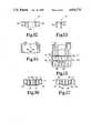
- FIG. 12is a rear elevational view of the release button top cap.
- FIG. 13is a side elevational view of the release button top cap.
- FIG. 14is a bottom view of the release button top cap.
- FIG. 15is a top plan view of the release slide without the top cap.
- FIG. 16is a section through the release slide assembly taken at the location of line 16--16 in FIG. 15 and viewed in the direction of the arrows and showing the cap latched in place.
- FIG. 17is a section through the release slide assembly taken at line 17--17 in FIG. 15 and viewed in the direction of the arrows and showing the cap latched in place.
- the exterior features of the buckle assemblyinclude a body 11, cover 12, and release button slide 13 and button front 14. These are all typically made of plastic and may be of a color or colors selected for desired esthetic effect.
- a buckle frame made of stamped steelis mounted in the body and includes a base 16, parallel upstanding sidewalls 17, a first pair of co-planar inwardly-turned and facing flanges or ears 18, (FIGS. 1 and 10) and a second lower or intermediate pair of co-planar inwardly turned and facing flanges or ears 19.
- the framehas a front flange 21 turned up from the base at the front and having an upper edge 22 which defines the lower edge of an entrance for a belt tongue inserted in the direction of arrow 23.
- the frame sidewallswhich are essentially identical to each other, have pawl pivot apertures 24 therein.
- the base 16has several centrally located rectangular apertures (FIG. 7). One of these is the belt connecting aperture 25.
- the other twoare ejector holder mounting apertures 26 receiving the front and rear latching feet 27A and 27B of the ejector holder 27. Shallow recesses are provided in the top surface of the bottom of the buckle body to receive and provide clearance for the latching lugs at the feet of the ejector holder.
- a conventional belt latching tonguecan be used with this buckle and typically includes a steel plate 29 having some non-abrasive cushion coating around the belt mounting portion, the latter having an aperture through the coating and plate to receive the belt 30 (FIG. 8) through it.
- a latching aperture 31 in the tongue platereceives a latching pawl 32 when the tongue is installed in the buckle as shown in FIG. 8.
- the pawl 32is formed on the top front end of a latching plate 33.
- the latching platehas a pair of pivot posts 34 (FIG. 2), one at each side, and each of which is received in one of the pawl pivot apertures 24 in the frame walls 17.
- the latching plate 33has an upturned rear arm 38 with a cam follower surface at its upper front edge 38A.
- the ejector holder 27has the spring seat post 27C and rear latching foot 27B at the top and bottom, respectively, of a rear wall 27E. It has front latching foot 27A at the bottom of front wall 27F.
- the ejector holderis made of a durable, low-friction plastic, having some resilience so that the front and rear feet can be pressed toward each other sufficiently during assembly to enter the holes 26, and then released to snap into secure engagement with the front and rear margins of the front and rear holes, respectively, with the hook portions of the feet retaining the feet on the base.
- the two longitudinally extending side walls 27G and 27H(FIGS.
- the ejectorhas inverted L-shapes providing a longitudinally extending groove which is of an inverted T-shape as best shown in FIG. 10 and which guidingly receives the ejector 43, which has laterally projecting lower side flanges 43A and 43B received in the groove of the ejector holder 27.
- the ejectoris also made of a durable low-friction plastic and is biased forward by a coil spring 44 (FIG. 7) whose rear end is received around the projecting boss and seated on the rear wall 27E of the ejector holder.
- the spring 44extends forward under spring 41 through the open space 46 (FIG.
- the ejectorhas a forwardly extending head 43A with a front end 43B which faces the approaching belt tongue.
- a pawl lock catchis provided by the boss 13C as it projects out from the release slide between the release cam surface 13F and the slide rear end flange 13R and, in fact, projects forwardly from the lower edge of flange 13R (FIG. 5) and laterally outward from the spring cavity wall of the slide (FIGS. 9 and 10).
- the latch plate arm 38has an inwardly projecting wing 38C (FIGS. 4, 9 and 10) which projects inwardly over the top of the pawl lock catch when the release button is in the normal rest position with the buckle latched as shown in FIGS. 8 and 9.
- the downwardly and rearwardly facing release cam surface 13F(FIGS. 3, 5 and 8) is provided on the slide and is engageable with the cam follower surface 38A as the slide is pushed to the rear in the direction of arrow 23 (FIG. 1). Pushing the slide to the rear causes the cam to drive the follower down, thus pivoting the latching plate 33 in a counterclockwise direction about the pivot edge 36 and against the urging of the spring 39. As the pivoting occurs, the pawl moves out of the aperture 31. When this occurs, the ejector slides forward (arrow 42 in FIG. 7) as forced to do so by the spring 44, pushing the tongue out of the buckle.
- the arrangement of the components, and particularly the slope of the cam 13F, distance of the cam follower edge from the pivot edge 36, location of the pawl edge 32A from the pivot edge,is such as to give a 4 to 1 mechanical advantage to the user pushing the end of the button 14 to release the buckle. Also it provides a half inch button travel from the latching rest position of FIG. 8 to a pawl release position shown dotted in FIG. 5. This is in a buckle whose overall dimensions are about 3.2 inches long, 1.2 inches high and 1.8 inches wide. This relatively significant button travel for release minimizes the chance of inadvertent release by the user.
- Use of the pivoting pawl and low-friction materials such as Teflon for the slide and ejectorcontribute to the ease of operation.
- the formed steel frame with the inwardly folded lower flanges 19 and upturned front flange 21support the tongue during prying loads.
- the inwardly folded upper flanges 18increase crush resistance and enhance protection of the internal components.
Landscapes
- Automotive Seat Belt Assembly (AREA)
- Buckles (AREA)
Abstract
Description
Claims (24)
Priority Applications (2)
| Application Number | Priority Date | Filing Date | Title |
|---|---|---|---|
| US07/160,405US4876772A (en) | 1988-02-25 | 1988-02-25 | Safety belt buckle |
| US07/357,805US4942649A (en) | 1988-02-25 | 1989-05-30 | Safety belt buckle |
Applications Claiming Priority (1)
| Application Number | Priority Date | Filing Date | Title |
|---|---|---|---|
| US07/160,405US4876772A (en) | 1988-02-25 | 1988-02-25 | Safety belt buckle |
Related Child Applications (1)
| Application Number | Title | Priority Date | Filing Date |
|---|---|---|---|
| US07/357,805Continuation-In-PartUS4942649A (en) | 1988-02-25 | 1989-05-30 | Safety belt buckle |
Publications (1)
| Publication Number | Publication Date |
|---|---|
| US4876772Atrue US4876772A (en) | 1989-10-31 |
Family
ID=22576775
Family Applications (1)
| Application Number | Title | Priority Date | Filing Date |
|---|---|---|---|
| US07/160,405Expired - LifetimeUS4876772A (en) | 1988-02-25 | 1988-02-25 | Safety belt buckle |
Country Status (1)
| Country | Link |
|---|---|
| US (1) | US4876772A (en) |
Cited By (24)
| Publication number | Priority date | Publication date | Assignee | Title |
|---|---|---|---|---|
| US5121528A (en)* | 1989-10-23 | 1992-06-16 | Kabushiki Kaisha Tokai-Rika-Denki-Seisakusho | Buckle device for seatbelt system |
| US5568676A (en)* | 1995-03-08 | 1996-10-29 | Indiana Mills And Manufacturing, Inc. | End release buckle |
| US6273505B1 (en) | 1999-10-22 | 2001-08-14 | Graco Children's Products Inc. | Web adjuster for infant products |
| US7093331B1 (en) | 2004-03-05 | 2006-08-22 | Amsafe Commercial Products, Inc. | Buckle and frame for restraint system resistant to a harsh environment |
| US20090038126A1 (en)* | 2007-08-08 | 2009-02-12 | Key Safety Systems, Inc. | Seat belt buckle |
| US7904997B2 (en) | 2008-11-07 | 2011-03-15 | Amsafe, Inc. | Buckles for inflatable personal restraint systems and associated systems and methods |
| USD655223S1 (en) | 2010-09-15 | 2012-03-06 | Amsafe Commercial Products, Inc. | Buckle assembly |
| USD661619S1 (en) | 2010-09-15 | 2012-06-12 | Amsafe Commercial Products, Inc. | Buckle assembly |
| US8303043B2 (en) | 2008-09-29 | 2012-11-06 | Amsafe, Inc. (Phoenix Group) | Tensioning apparatuses for occupant restraint systems and associated systems and methods |
| US8327513B2 (en) | 2005-06-09 | 2012-12-11 | Amsafe, Inc. | Buckle assembly having single release for multiple belt connectors |
| US8393645B2 (en) | 2009-11-02 | 2013-03-12 | Amsafe Commercial Products, Inc. | Devices for adjusting tension in seat belts and other restraint system webs, and associated methods |
| US8627554B1 (en) | 2010-05-03 | 2014-01-14 | Amsafe, Inc. (Phoenix Group) | Buckle assemblies with swivel and dual release features and associated methods of use and manufacture |
| US8683666B2 (en) | 2009-11-04 | 2014-04-01 | Amsafe Commercial Products, Inc. | Restraint system buckle components having tactile surfaces, and associated methods of use and manufacture |
| US8777323B2 (en) | 2010-07-20 | 2014-07-15 | Amsafe, Inc. | Restraint harnesses and associated methods of use and manufacture |
| US8820789B2 (en) | 2009-02-23 | 2014-09-02 | Amsafe, Inc. | Seat harness pretensioner |
| US9022483B2 (en) | 2012-06-07 | 2015-05-05 | Shield Restraint Systems, Inc. | Seatbelt buckle tongue assembly |
| US9119445B2 (en) | 2013-02-19 | 2015-09-01 | Amsafe, Inc. | Buckle assemblies with lift latches and associated methods and systems |
| US9277788B2 (en) | 2013-02-19 | 2016-03-08 | Amsafe, Inc. | Dual release buckle assemblies and associated systems and methods |
| US9775410B2 (en) | 2014-12-16 | 2017-10-03 | Shield Restraint Systems, Inc. | Web adjusters for use with restraint systems and associated methods of use and manufacture |
| US9814282B2 (en) | 2016-02-02 | 2017-11-14 | Shield Restraint Systems, Inc. | Harsh environment buckle assemblies and associated systems and methods |
| US10086795B2 (en) | 2015-10-02 | 2018-10-02 | Shield Restraint Systems, Inc. | Load indicators for personal restraint systems and associated systems and methods |
| US10604259B2 (en) | 2016-01-20 | 2020-03-31 | Amsafe, Inc. | Occupant restraint systems having extending restraints, and associated systems and methods |
| US10611334B2 (en) | 2017-02-07 | 2020-04-07 | Shield Restraint Systems, Inc. | Web adjuster |
| US11219280B2 (en)* | 2017-11-30 | 2022-01-11 | Husqvarna Ab | Tool belt |
Citations (31)
| Publication number | Priority date | Publication date | Assignee | Title |
|---|---|---|---|---|
| US3396437A (en)* | 1966-08-17 | 1968-08-13 | Britax London Ltd | Slimline safety belt buckle |
| US3440697A (en)* | 1965-08-20 | 1969-04-29 | Britax London Ltd | Buckles for safety belts |
| US4121327A (en)* | 1977-08-01 | 1978-10-24 | Irvin Industries Inc. | Clip ejector for safety seat belt buckle |
| US4127922A (en)* | 1976-02-18 | 1978-12-05 | Nsk-Warner, K.K. | Latch device for a safety belt buckle in a vehicle and method of assembling the same |
| US4128924A (en)* | 1977-02-17 | 1978-12-12 | Indiana Mills & Manufacturing Inc. | Laminated seat belt buckle |
| US4182008A (en)* | 1976-04-28 | 1980-01-08 | Aciers Et Outillage Peugeot | Buckle for a safety belt |
| US4195392A (en)* | 1976-06-30 | 1980-04-01 | Nsk-Warner K.K. | Seat belt buckle device |
| US4197619A (en)* | 1978-09-22 | 1980-04-15 | Britax (Wingard) Limited | Tongue and buckle fastener for a safety belt harness |
| GB1589059A (en)* | 1978-05-12 | 1981-05-07 | Securon Ag | Buckle for safety belts and seat belts |
| US4313246A (en)* | 1979-07-23 | 1982-02-02 | Repa Feinstanzwerk Gmbh | Belt buckle or lock for a safety belt |
| US4358879A (en)* | 1980-12-01 | 1982-11-16 | General Motors Corporation | Seat belt buckle |
| US4368563A (en)* | 1981-07-13 | 1983-01-18 | Allied Corporation | Seat belt buckle with plastic cover |
| US4382320A (en)* | 1980-09-02 | 1983-05-10 | Fuji Kiko Kabushiki Kaisha | Seat belt buckle |
| US4385425A (en)* | 1980-06-30 | 1983-05-31 | Kabushiki-Kaisha, Tokai-Rika-Denki-Seisakusho | Buckling device for vehicle seat belt |
| US4388746A (en)* | 1980-11-18 | 1983-06-21 | Autoflug-Stakupress Gmbh & Co. | Buckle for a safety belt |
| US4393557A (en)* | 1980-05-14 | 1983-07-19 | Aciers Et Outillage Peugeot | Safety belt buckle |
| US4394792A (en)* | 1980-05-14 | 1983-07-26 | Aciers Et Outillage Peugeot | Buckle for a safety belt |
| US4403376A (en)* | 1980-12-18 | 1983-09-13 | Autoflug Gmbh | Central belt lock, particularly for aircraft safety belt |
| US4425688A (en)* | 1981-11-06 | 1984-01-17 | Indiana Mills & Manufacturing, Inc. | Child belt buckle |
| US4527317A (en)* | 1982-01-13 | 1985-07-09 | Autoflug-Stakupress Gmbh & Co. | Buckle for a safety belt |
| US4535514A (en)* | 1982-09-27 | 1985-08-20 | Gateway Industries, Inc. | Seat belt with plastic cover |
| US4543693A (en)* | 1982-07-02 | 1985-10-01 | Britax (Wingard) Limited | Safety belt buckles |
| US4562625A (en)* | 1983-12-21 | 1986-01-07 | Gateway Industries, Inc. | Seat belt buckle |
| US4577378A (en)* | 1983-06-21 | 1986-03-25 | Autoflug Gmbh | Buckle for safety belts |
| US4587696A (en)* | 1982-11-30 | 1986-05-13 | Nsk Warner K. K. | Buckle for seat belt |
| US4611369A (en)* | 1985-02-25 | 1986-09-16 | Trw Repa Gmbh | Belt lock for a safety belt |
| US4614010A (en)* | 1985-06-03 | 1986-09-30 | Trw Inc. | Safety belt buckle |
| US4617705A (en)* | 1985-08-05 | 1986-10-21 | Indiana Mills & Manufacturing, Inc. | Child belt buckle |
| US4677715A (en)* | 1985-07-17 | 1987-07-07 | Aciers Et Outillage Peugeot | Buckle, especially for a safety belt |
| US4677716A (en)* | 1985-06-10 | 1987-07-07 | Aciers Et Outillage Peugeot | Buckle in particular for a safety belt |
| US4692970A (en)* | 1985-08-05 | 1987-09-15 | Indiana Mills & Manufacturing, Inc. | Belt buckle with eject means |
- 1988
- 1988-02-25USUS07/160,405patent/US4876772A/ennot_activeExpired - Lifetime
Patent Citations (32)
| Publication number | Priority date | Publication date | Assignee | Title |
|---|---|---|---|---|
| US3440697A (en)* | 1965-08-20 | 1969-04-29 | Britax London Ltd | Buckles for safety belts |
| US3396437A (en)* | 1966-08-17 | 1968-08-13 | Britax London Ltd | Slimline safety belt buckle |
| US4127922A (en)* | 1976-02-18 | 1978-12-05 | Nsk-Warner, K.K. | Latch device for a safety belt buckle in a vehicle and method of assembling the same |
| US4182008A (en)* | 1976-04-28 | 1980-01-08 | Aciers Et Outillage Peugeot | Buckle for a safety belt |
| US4195392A (en)* | 1976-06-30 | 1980-04-01 | Nsk-Warner K.K. | Seat belt buckle device |
| US4128924A (en)* | 1977-02-17 | 1978-12-12 | Indiana Mills & Manufacturing Inc. | Laminated seat belt buckle |
| US4121327A (en)* | 1977-08-01 | 1978-10-24 | Irvin Industries Inc. | Clip ejector for safety seat belt buckle |
| GB1589059A (en)* | 1978-05-12 | 1981-05-07 | Securon Ag | Buckle for safety belts and seat belts |
| US4197619A (en)* | 1978-09-22 | 1980-04-15 | Britax (Wingard) Limited | Tongue and buckle fastener for a safety belt harness |
| US4301576A (en)* | 1978-09-22 | 1981-11-24 | Britax (Wingard) Limited | Tongue and buckle fastener for a safety belt harness |
| US4313246A (en)* | 1979-07-23 | 1982-02-02 | Repa Feinstanzwerk Gmbh | Belt buckle or lock for a safety belt |
| US4393557A (en)* | 1980-05-14 | 1983-07-19 | Aciers Et Outillage Peugeot | Safety belt buckle |
| US4394792A (en)* | 1980-05-14 | 1983-07-26 | Aciers Et Outillage Peugeot | Buckle for a safety belt |
| US4385425A (en)* | 1980-06-30 | 1983-05-31 | Kabushiki-Kaisha, Tokai-Rika-Denki-Seisakusho | Buckling device for vehicle seat belt |
| US4382320A (en)* | 1980-09-02 | 1983-05-10 | Fuji Kiko Kabushiki Kaisha | Seat belt buckle |
| US4388746A (en)* | 1980-11-18 | 1983-06-21 | Autoflug-Stakupress Gmbh & Co. | Buckle for a safety belt |
| US4358879A (en)* | 1980-12-01 | 1982-11-16 | General Motors Corporation | Seat belt buckle |
| US4403376A (en)* | 1980-12-18 | 1983-09-13 | Autoflug Gmbh | Central belt lock, particularly for aircraft safety belt |
| US4368563A (en)* | 1981-07-13 | 1983-01-18 | Allied Corporation | Seat belt buckle with plastic cover |
| US4425688A (en)* | 1981-11-06 | 1984-01-17 | Indiana Mills & Manufacturing, Inc. | Child belt buckle |
| US4527317A (en)* | 1982-01-13 | 1985-07-09 | Autoflug-Stakupress Gmbh & Co. | Buckle for a safety belt |
| US4543693A (en)* | 1982-07-02 | 1985-10-01 | Britax (Wingard) Limited | Safety belt buckles |
| US4535514A (en)* | 1982-09-27 | 1985-08-20 | Gateway Industries, Inc. | Seat belt with plastic cover |
| US4587696A (en)* | 1982-11-30 | 1986-05-13 | Nsk Warner K. K. | Buckle for seat belt |
| US4577378A (en)* | 1983-06-21 | 1986-03-25 | Autoflug Gmbh | Buckle for safety belts |
| US4562625A (en)* | 1983-12-21 | 1986-01-07 | Gateway Industries, Inc. | Seat belt buckle |
| US4611369A (en)* | 1985-02-25 | 1986-09-16 | Trw Repa Gmbh | Belt lock for a safety belt |
| US4614010A (en)* | 1985-06-03 | 1986-09-30 | Trw Inc. | Safety belt buckle |
| US4677716A (en)* | 1985-06-10 | 1987-07-07 | Aciers Et Outillage Peugeot | Buckle in particular for a safety belt |
| US4677715A (en)* | 1985-07-17 | 1987-07-07 | Aciers Et Outillage Peugeot | Buckle, especially for a safety belt |
| US4617705A (en)* | 1985-08-05 | 1986-10-21 | Indiana Mills & Manufacturing, Inc. | Child belt buckle |
| US4692970A (en)* | 1985-08-05 | 1987-09-15 | Indiana Mills & Manufacturing, Inc. | Belt buckle with eject means |
Cited By (27)
| Publication number | Priority date | Publication date | Assignee | Title |
|---|---|---|---|---|
| US5121528A (en)* | 1989-10-23 | 1992-06-16 | Kabushiki Kaisha Tokai-Rika-Denki-Seisakusho | Buckle device for seatbelt system |
| US5568676A (en)* | 1995-03-08 | 1996-10-29 | Indiana Mills And Manufacturing, Inc. | End release buckle |
| US6273505B1 (en) | 1999-10-22 | 2001-08-14 | Graco Children's Products Inc. | Web adjuster for infant products |
| US7093331B1 (en) | 2004-03-05 | 2006-08-22 | Amsafe Commercial Products, Inc. | Buckle and frame for restraint system resistant to a harsh environment |
| US8567022B2 (en) | 2005-06-09 | 2013-10-29 | Amsafe, Inc. | Buckle assembly having single release for multiple belt connectors |
| US8327513B2 (en) | 2005-06-09 | 2012-12-11 | Amsafe, Inc. | Buckle assembly having single release for multiple belt connectors |
| US20090038126A1 (en)* | 2007-08-08 | 2009-02-12 | Key Safety Systems, Inc. | Seat belt buckle |
| US20120198665A1 (en)* | 2007-08-08 | 2012-08-09 | Key Safety Systems, Inc. | Seat belt buckle |
| US8303043B2 (en) | 2008-09-29 | 2012-11-06 | Amsafe, Inc. (Phoenix Group) | Tensioning apparatuses for occupant restraint systems and associated systems and methods |
| US8632131B2 (en) | 2008-09-29 | 2014-01-21 | Amsafe, Inc. | Tensioning apparatuses for occupant restraint systems and associated systems and methods |
| US7904997B2 (en) | 2008-11-07 | 2011-03-15 | Amsafe, Inc. | Buckles for inflatable personal restraint systems and associated systems and methods |
| US8820789B2 (en) | 2009-02-23 | 2014-09-02 | Amsafe, Inc. | Seat harness pretensioner |
| US8393645B2 (en) | 2009-11-02 | 2013-03-12 | Amsafe Commercial Products, Inc. | Devices for adjusting tension in seat belts and other restraint system webs, and associated methods |
| US8683666B2 (en) | 2009-11-04 | 2014-04-01 | Amsafe Commercial Products, Inc. | Restraint system buckle components having tactile surfaces, and associated methods of use and manufacture |
| US8627554B1 (en) | 2010-05-03 | 2014-01-14 | Amsafe, Inc. (Phoenix Group) | Buckle assemblies with swivel and dual release features and associated methods of use and manufacture |
| US8777323B2 (en) | 2010-07-20 | 2014-07-15 | Amsafe, Inc. | Restraint harnesses and associated methods of use and manufacture |
| USD655223S1 (en) | 2010-09-15 | 2012-03-06 | Amsafe Commercial Products, Inc. | Buckle assembly |
| USD661619S1 (en) | 2010-09-15 | 2012-06-12 | Amsafe Commercial Products, Inc. | Buckle assembly |
| US9022483B2 (en) | 2012-06-07 | 2015-05-05 | Shield Restraint Systems, Inc. | Seatbelt buckle tongue assembly |
| US9119445B2 (en) | 2013-02-19 | 2015-09-01 | Amsafe, Inc. | Buckle assemblies with lift latches and associated methods and systems |
| US9277788B2 (en) | 2013-02-19 | 2016-03-08 | Amsafe, Inc. | Dual release buckle assemblies and associated systems and methods |
| US9775410B2 (en) | 2014-12-16 | 2017-10-03 | Shield Restraint Systems, Inc. | Web adjusters for use with restraint systems and associated methods of use and manufacture |
| US10086795B2 (en) | 2015-10-02 | 2018-10-02 | Shield Restraint Systems, Inc. | Load indicators for personal restraint systems and associated systems and methods |
| US10604259B2 (en) | 2016-01-20 | 2020-03-31 | Amsafe, Inc. | Occupant restraint systems having extending restraints, and associated systems and methods |
| US9814282B2 (en) | 2016-02-02 | 2017-11-14 | Shield Restraint Systems, Inc. | Harsh environment buckle assemblies and associated systems and methods |
| US10611334B2 (en) | 2017-02-07 | 2020-04-07 | Shield Restraint Systems, Inc. | Web adjuster |
| US11219280B2 (en)* | 2017-11-30 | 2022-01-11 | Husqvarna Ab | Tool belt |
Similar Documents
| Publication | Publication Date | Title |
|---|---|---|
| US4876772A (en) | Safety belt buckle | |
| EP0401455B1 (en) | Safety belt buckle | |
| EP0608564B1 (en) | Belt buckle with interactive dual tongues | |
| US4196500A (en) | Seat belt buckle | |
| KR100275417B1 (en) | Slide fastener slider | |
| US5526556A (en) | Buckle for vehicle seat | |
| US5588189A (en) | Buckle for vehicle seat belt system | |
| US5267377A (en) | Buckle assembly | |
| US4358879A (en) | Seat belt buckle | |
| US4197619A (en) | Tongue and buckle fastener for a safety belt harness | |
| US4094046A (en) | Seat belt buckle | |
| US4703542A (en) | Buckle for seat belts | |
| US4797984A (en) | Seat belt buckle | |
| US4027362A (en) | Buckles for vehicle safety belts | |
| US3566455A (en) | Restraint belt buckle cover | |
| EP0719506B1 (en) | Buckle for seat belt device | |
| US3494007A (en) | Safety belt buckle | |
| US4358878A (en) | Plug-in fastener for motor vehicle safety belts | |
| US3440697A (en) | Buckles for safety belts | |
| US4310954A (en) | Buckle | |
| JP3455428B2 (en) | Buckle switch and buckle | |
| US7093331B1 (en) | Buckle and frame for restraint system resistant to a harsh environment | |
| US3533141A (en) | Pushbutton safety belt buckle | |
| US3582136A (en) | Pushbutton buckle with locking means for stud | |
| GB2073810A (en) | Improvements in or relating to a buckle |
Legal Events
| Date | Code | Title | Description |
|---|---|---|---|
| AS | Assignment | Owner name:INDIANA MILLS & MANUFACTURING, INC., 18881 U.S. 31 Free format text:ASSIGNMENT OF ASSIGNORS INTEREST.;ASSIGNORS:ANTHONY, JAMES R.;MERRICK, DAVID;HOMEIER, RONALD F.;AND OTHERS;REEL/FRAME:004873/0281 Effective date:19880219 Owner name:INDIANA MILLS & MANUFACTURING, INC., A CORP. OF IN Free format text:ASSIGNMENT OF ASSIGNORS INTEREST;ASSIGNORS:ANTHONY, JAMES R.;MERRICK, DAVID;HOMEIER, RONALD F.;AND OTHERS;REEL/FRAME:004873/0281 Effective date:19880219 | |
| STCF | Information on status: patent grant | Free format text:PATENTED CASE | |
| FEPP | Fee payment procedure | Free format text:PAYOR NUMBER ASSIGNED (ORIGINAL EVENT CODE: ASPN); ENTITY STATUS OF PATENT OWNER: LARGE ENTITY | |
| FPAY | Fee payment | Year of fee payment:4 | |
| FPAY | Fee payment | Year of fee payment:8 | |
| FEPP | Fee payment procedure | Free format text:PAT HLDR NO LONGER CLAIMS SMALL ENT STAT AS INDIV INVENTOR (ORIGINAL EVENT CODE: LSM1); ENTITY STATUS OF PATENT OWNER: LARGE ENTITY | |
| FPAY | Fee payment | Year of fee payment:12 |