US4876591A - Color video signal generating device using monochrome and color image sensors having different resolutions to form a luminance signal - Google Patents
Color video signal generating device using monochrome and color image sensors having different resolutions to form a luminance signalDownload PDFInfo
- Publication number
- US4876591A US4876591AUS07/309,655US30965589AUS4876591AUS 4876591 AUS4876591 AUS 4876591AUS 30965589 AUS30965589 AUS 30965589AUS 4876591 AUS4876591 AUS 4876591A
- Authority
- US
- United States
- Prior art keywords
- color
- luminance signal
- signal
- monochrome
- frequency band
- Prior art date
- Legal status (The legal status is an assumption and is not a legal conclusion. Google has not performed a legal analysis and makes no representation as to the accuracy of the status listed.)
- Expired - Lifetime
Links
Images


Classifications
- H—ELECTRICITY
- H04—ELECTRIC COMMUNICATION TECHNIQUE
- H04N—PICTORIAL COMMUNICATION, e.g. TELEVISION
- H04N23/00—Cameras or camera modules comprising electronic image sensors; Control thereof
- H04N23/80—Camera processing pipelines; Components thereof
- H04N23/84—Camera processing pipelines; Components thereof for processing colour signals
- H04N23/843—Demosaicing, e.g. interpolating colour pixel values
- H—ELECTRICITY
- H04—ELECTRIC COMMUNICATION TECHNIQUE
- H04N—PICTORIAL COMMUNICATION, e.g. TELEVISION
- H04N25/00—Circuitry of solid-state image sensors [SSIS]; Control thereof
- H04N25/10—Circuitry of solid-state image sensors [SSIS]; Control thereof for transforming different wavelengths into image signals
- H04N25/11—Arrangement of colour filter arrays [CFA]; Filter mosaics
Definitions
- the present inventionrelates to a video signal generating device in which a solid-state color image sensor detects the optical image of an object to provide electrical video signals utilized to form a luminance signal and color difference signals.
- a video signal generating deviceprovided in an electronic still camera or color video camera employs a solid-state image sensor having color filters for producing primary or complementary color signals so as to produce luminance signals and color difference signals according to the color video signals outputted by the solid-state image sensor.
- FIG. 1shows the arrangement of a conventional video signal generating device in a double-sensor type color camera or the like.
- a two-color separation dichroic prism 2is provided behind an image pickup lens 1, the prism 2 being used to separate the incident light beam into green and red-blue beams.
- An optical image formed by the red and blue light beamsis received through an optical low-pass crystal filter 16 on a red-and-blue image sensor 3, on the surface of which is formed a red (R) and blue (B) stripe color filter array, the picture elements of which are horizontally scanned to provide red (R) and blue (B) color video signals.
- an optical image formed by the green light beamis received through an optical low-pass crystal filter 17 on a green image sensor 4, on the surface of which a green (G) color filter is provided, the picture elements of which are horizontally scanned to provide a green (G) color video signal.
- the red, green and blue color video signalsare outputted sequentially with a predetermined timing.
- the green color video signal Gis applied through a preamplifier 5 to a low-pass filter 7 having a passband of from 0 to 4.2 MHz, where it is converted into a green signal G o whose frequency is limited by the passband.
- the output signal G ois applied to a subtractor 10 and through another low-pass filter 11.
- the low-pass filter 11which has a passband of from 0 to 0.7 MHz, outputs a green signal G L whose frequency is limited by the passband.
- the output signal G Lis applied to matrix circuit 14 (described below in detail) and to the subtraction input terminal (-) of the subtractor 10.
- the red color video signal Rsampled by a sample-and-hold circuit 8 is applied to a low-pass filter 12 having a passband of from 0 to 0.7 MHz, where it is converted into a red signal R L whose frequency is limited by this passband.
- the blue color video signal Bsampled by a sample-and-hold circuit 9 is applied to a low-pass filter 13 having a passband of from 0 to 0.7 MHz, where it is converted into a blue signal B L Whose frequency is limited by the passband.
- the red signal R L and the blue signal B Lare applied to the matrix circuit 14.
- a low frequency luminance signal Y L having a frequency band of from 0 to 0.7 MHzis formed according to the red, blue and green signals R L , B L and G L having a frequency band of from 0 to 0.7 MHz, and the low frequency luminance signal Y L and the high frequency luminance signal Y H being subjected to addition to form the luminance signal.
- color difference signals R L -Y L and B L -Y Lare formed according to the red and blue signals R L and B L and the low frequency luminance signal Y L .
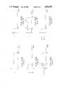
- FIGS. 2A to 2Fillustrate frequency characteristics of the signals produced in the above-described signal processing operations.
- the red, blue and green signals R L , B L and G L , the low frequency luminance signal Y L and the color difference signal R L -Y L and B L -Y Lhave a frequency band of from 0 to 0.7 MHz.
- the high frequency luminance signal Y Hhas a frequency band of from 0.7 MHz to 4.2 MHz (with the shaded part being omitted).
- the luminance signal Ybeing finally formed through the addition of the high frequency luminance signal Y H and the low frequency luminance signal Y L , has a frequency band of from 0 MHz to 4.2 MHz, as indicated in FIG. 2E.
- a conventional video signal generating device in a single-sensor type color camerawill be described with reference to FIG. 3.
- An optical low-pass crystal filter 41is disposed behind an image pickup lens 21.
- a color filter 22 having a stripe-shaped or mosaic-shaped red (R), blue (B) and green (G) color filter arrayis attached to a solid-state image sensor 23.
- electrical signals produced from the picture elementsare horizontally scanned.
- the output of the sensor 23is supplied to a preamplifier 24, which outputs a color video signal.
- the color video signal thus outputtedis supplied to a color separation circuit 26 to obtain the color signals R, G and B.
- the green signal Gis applied to a low-pass filter 27 having a passband of from 0 to 4.2 MHz, where it is converted into a green signal G o whose frequency is limited by the passband.
- the green signal G ois supplied directly to one input terminal (+) of a subtraction circuit 31, while it is supplied through another low-pass filter 30 having a passband of from 0 to 0.7 MHz to the other input terminal (-) of the subtraction circuit 31; That is, a green signal G L is applied to the minus input terminal (-) of the circuit 31.
- the green signal G Lis further applied to a process circuit 32 where it is subjected to gamma correction, for instance.
- the output of the process circuit 32is applied to one input terminal of a luminance signal amplifier circuit 35.
- the red signal Ris supplied to a low-pass filter 28 having a passband of from 0 to 0.7 MHz, where it is converted into a red signal R L whose frequency is limited by the passband.
- the red signal R Lafter being subjected, for instance, to gamma correction by a process circuit 33, is applied to another input terminal of the luminance signal amplifier circuit 35, and to a modulation circuit 36 for forming a color difference signal.
- the blue signal Bis supplied to a low-pass filter 29 having a passband of from 0 to 0.7 MHz, where it is converted to a blue signal B L whose frequency is limited by the passband.
- the blue signal B Lafter being subjected, for instance, to gamma correction by a process circuit 34, is applied to the remaining input terminal of the luminance signal amplifier circuit 35 and to a modulation circuit 37 for forming a color difference signal.
- the luminance signal amplifier circuit 35forms a low frequency luminance signal Y L having a frequency band of from 0 to 0.7 MHz according to the red, blue and green signals, R L , B L and G L , the frequencies of which have been limited by the passband of 0 to 0.7 MHz of the low-pass filters 28, 29 and 30, respectively.
- the modulation circuit 36forms a color difference signal R L -Y L according to the red signal R L and the low frequency luminance signal Y L .
- the modulation circuit 37forms a color difference signal B L -Y l according to the blue signal B L and the low frequency luminance signal Y L .
- Sub carriers S B1 and S B2 different in frequency from one anotherare supplied to the modulation circuits 36 and 37, respectively.
- a mixer 38the high frequency luminance signal G H and the low frequency luminance signal Y L are mixed to produce a luminance signal Y having a frequency band of from 0 to 4.2 MHz.
- Another mixer 39mixes the color difference signals R L -Y L and B L -Y L to provide an output signal.
- a third mixer 40mixes the luminance signal Y, the output signal of the mixer 39, and a synchronizing signal S c to output a video signal conforming to the NTSC system, for instance.
- the subtractor 10forms the high frequency luminance signal Y H utilizing only the green signal produced by the green image sensor 4. Assuming that the optical image has substantially no green (G) color video signal, there is a possibility that it may be somewhat difficult to obtain the high frequency luminance signal Y H . As a result, luminance distortion which may be caused by the absence of a green component, is produced between the luminance signal Y H and the red and blue signals outputted by the red and blue image sensor 3. Furthermore, since the green and red and blue sensors are separately provided, color shift due to picture element shift is liable to occur because it is difficult to manufacture the device with a very high accuracy. In addition, because the image sensors 3 and 4 are covered by color filters, the device generally has a reduced light-detecting sensitivity.
- an object of the inventionis to provide a video signal generating device having an improved resolution and in which the occurrence of color Moire is suppressed.
- a video signal generating devicewhich, according to the invention, comprises: means for dividing the optical image of an object received through an image pickup optical system into first and second optical images; a monochrome image sensor having a first Nyquist spatial frequency band in the horizontal direction and receiving the first optical image; a color image sensor having a color filter array on the surface thereof and having a second Nyquist spatial frequency band in the horizontal direction which is lower than that of the first Nyquist spatial band; optical low-pass means for limiting the second optical image to a spatial frequency band lower than the first Nyquist spatial frequency band prior to reception by the color image sensor; a matrix circuit for forming, in response to color signals outputted by the color images sensor, a low frequency luminance signal and color difference signals whose frequency bands are lower than the second Nyquist spatial frequency band; means for adding the low frequency luminance signal to a part of a high frequency luminance signal outputted by the monochrome image sensor which is higher in frequency band
- the overall resolutionis determined by the first Nyquist spatial frequency band of the monochrome image sensor, and hence the resolution is improved. Furthermore, for instance, red, blue and green color signals produced by the color image sensor can be made to have equal spatial frequency characteristics, and signal components higher in frequency than the second Nyquist spatial frequency band can be removed from the color signals by means of the optical low-pass filtering means, with the result that the occurrence of color Moire is suppressed.
- the color filter arrayis preferably composed of stripe shaped red, green and blue filters.
- the luminance signal forming meansis preferably designed so as to produce a difference signal between the high frequency luminance signal outputted by the monochrome image sensor and a low frequency luminance signal provided by the color image sensor in such a manner that the difference signal is limited to a frequency band equal to the low frequency band, and to add the difference signal thus limited in frequency band to the high frequency luminance signal.
- no two-color separation dichroic prism 2is required in an optical path, and therefore it is possible to increase sensitivity in obtaining the high frequency luminance signal Y H .
- FIG. 1is a block diagram showing a conventional video signal generating device
- FIGS. 2(A) to 2(F)are characteristic diagrams showing the frequency characteristics of various signals produced in the device of FIG. 1;
- FIG. 3is a block diagram showing another example of a conventional video signal generating device.
- FIG. 4is a block diagram showing an example of a video signal generating device constructed according to the invention.
- reference numeral 51designates an image pickup lens.
- a half-silvered mirror 52is disposed behind the lens 51 in the optical path.
- the optical image reflected from the half-silvered mirror 52is formed on a solid-state image sensor 57, for instance, of the CCD type.
- an optical low-pass crystal filter 70is provided in front of the image sensor 57.
- the color filter 54is a stripe-shaped color filter is which stripe-shaped red (R), blue (B) and green (G) color filters are alternately arranged in the horizontal scanning direction at equal intervals.
- the image sensor 55(hereinafter referred to as a color image sensor) horizontally scans the picture elements to read out color signals R, G and B in the stated order.
- the image sensor 57(hereinafter referred to as monochrome image sensor), having no color filter, outputs a signal the level of which corresponds to luminance instead of hue.
- the monochrome image sensor 57thus provides a high frequency luminance signal (as described in more detail below), and accordingly its provision relates directly to the desired improvement in resolution.
- the picture element resolution of the monochrome image sensor 57is made higher than that of the color image sensor 55.
- the Nyquist spatial frequency band for the monochrome image sensor 57is higher than that of the color image sensor 55.
- the optical low-pass filter 53has a characteristic such that the optical image passed through the half-silvered mirror 52 is limited to a spatial frequency band lower than the Nyquist spatial frequency band of the image impressed on sensor 57. Accordingly, the color image sensor 55 produces no unwanted high frequency signal which can spread to the frequency band of the high frequency luminance signal, and hence the occurrence of luminance distortion is suppressed.
- the output color signals R, G and B of the color image sensor 55are applied through a preamplifier 56 to sample-and-hold circuits 59, 61 and 63, respectfully, in synchronization with the read timing in the horizontal scanning operation.
- the output color signals R L , B L and G L from the low-pass filters 60, 62 and 64are applied through process circuits 73, 74 and 75 to a low frequency luminance signal forming circuit 65 and a matrix circuit 68, respectively.
- the process circuits 73, 74 and 75are the same as those 32, 33 and 34 shown in FIG. 3.
- the low frequency luminance signal forming circuit 65mixes the colors signals R L , B L and G L in the ratio determined by the following expression to form a low frequency luminance signal Y L :
- the luminance signal Y Lis applied to one input terminal of the matrix circuit 68.
- the signal W outputted by the monochrome image sensor 57is applied through a preamplifier 58 to a low-pass filter 66 having a passband of from 0 to 4.2 MHz, where it is converted into a signal W o whose frequency is limited by the passband.
- the signal W ois applied to an input terminal (+) of the subtraction circuit 67.
- the signal W o of the low-pass filter 66is supplied through another low-pass filter 72 having a passband of from 0 to 0.7 MHz to the other input terminal (-) of the subtraction circuit 67.
- the high frequency luminance signal Y H thus formedis applied to the matrix circuit 68.
- the output of the low frequency luminance signal forming circuit 65may be applied to the other input terminal (-) of the subtraction circuit 67 to obtain the same function.
- the luminance signal Y and the color difference signals R L -Y L and B L -Y Lare mixed by a color encoder circuit 69 to provide a video signal.
- the signal W o applied to the subtraction circuit 67 by the monochrome image sensor 57corresponds to the signal G o shown in FIG. 2A
- the red, blue and green signal R L , B L and G L , outputted respectively by the low-pass filters 60, 62 and 64,correspond to those shown in FIG. 2B
- the low frequency luminance signal Y L produced by the low frequency luminance signal forming circuit 65corresponds to that in FIG. 2D
- the high frequency luminance signal Y Hcorresponds to that shown in FIG. 2C
- the luminance signal Y and the color difference signals R L -Y L and B L -Y Lcorrespond to the signal shown in FIG. 2E and those in FIG. 2F, respectively.
- the high frequency luminance signal Y His formed by subtraction of the low frequency signal Y L from the signal W o , Y L being formed by the low pass filter 72 from the signal W o outputted by the monochrome image sensor 57. Therefore, the low frequency components of the signal W o are eliminated, and the occurrence of luminance distortion between the low frequency luminance signal Y L and the high frequency luminance signal Y H is prevented.
- the color filter 54is constructed such that stripe-shaped color filters are arranged at equal intervals. Therefore, the spatial frequency characteristics obtained for the red, blue and green hues are identical, and, for each of the hues, horizontal and vertical Nyquist frequency bands are made equal to one another.
- the unwanted high frequency components of the optical imageare removed by the optical low-pass filter 53, the occurrence of color Moire is suppressed.
- the resolutionis determined by the high frequency luminance signal Y H obtained through the monochrome image sensor 57, the resultant image is free from color Moire; that is, it has a high resolution.
- the video signal generating device of the inventioncomprises: the optical components which divide the optical image received through the image pickup optical system into first and second optical images; the monochrome image scanner having a first Nyquist spatial frequency band in the horizontal direction and which receives the first optical image; the color image sensor having a second Nyquist spatial frequency band in the horizontal direction lower than the first Nyquist spatial frequency band of the monochrome image sensor and having a color filter array on the surface thereof; the optical low-pass filter for limiting the second optical image to the spatial frequency band lower than the first Nyquist spatial frequency band; the matrix circuit for forming, according to the color signals outputted by the color image sensor, the luminance signal and the color difference signals whose frequency bands are lower than the first Nyquist spatial frequency band; the circuit for adding the low frequency luminance signal to the part of the high frequency luminance signal outputted by the monochrome image sensor, which is higher in frequency than the spatial frequency band of the low frequency luminance signal, to form the luminance signal; and the circuit for producing the video signal
- the resolutionis determined according to the first Nyquist spatial frequency, as a result of which the overall resolution is greatly improved. Furthermore, the color signals produced by the color image sensor are made equal in spatial frequency characteristics, and signal components higher in frequency than the second Nyquist spatial frequency band are removed from the color signals, with the result that the occurrence of color Moire is suppressed.
Landscapes
- Engineering & Computer Science (AREA)
- Multimedia (AREA)
- Signal Processing (AREA)
- Color Television Image Signal Generators (AREA)
Abstract
Description
Y.sub.L =0.30 R.sub.L +0.59G.sub.L +0.11B.sub.L
Claims (1)
Applications Claiming Priority (2)
| Application Number | Priority Date | Filing Date | Title |
|---|---|---|---|
| JP61301688AJP2849813B2 (en) | 1986-12-19 | 1986-12-19 | Video signal forming device |
| JP61-301688 | 1986-12-19 |
Related Parent Applications (1)
| Application Number | Title | Priority Date | Filing Date |
|---|---|---|---|
| US07/134,748ContinuationUS4823186A (en) | 1986-12-19 | 1987-12-18 | Color video signal generating device using monochrome and color image sensors having different resolutions to form a luminance signal |
Publications (1)
| Publication Number | Publication Date |
|---|---|
| US4876591Atrue US4876591A (en) | 1989-10-24 |
Family
ID=17899945
Family Applications (2)
| Application Number | Title | Priority Date | Filing Date |
|---|---|---|---|
| US07/134,748Expired - LifetimeUS4823186A (en) | 1986-12-19 | 1987-12-18 | Color video signal generating device using monochrome and color image sensors having different resolutions to form a luminance signal |
| US07/309,655Expired - LifetimeUS4876591A (en) | 1986-12-19 | 1989-02-13 | Color video signal generating device using monochrome and color image sensors having different resolutions to form a luminance signal |
Family Applications Before (1)
| Application Number | Title | Priority Date | Filing Date |
|---|---|---|---|
| US07/134,748Expired - LifetimeUS4823186A (en) | 1986-12-19 | 1987-12-18 | Color video signal generating device using monochrome and color image sensors having different resolutions to form a luminance signal |
Country Status (4)
| Country | Link |
|---|---|
| US (2) | US4823186A (en) |
| EP (1) | EP0272634B1 (en) |
| JP (1) | JP2849813B2 (en) |
| DE (1) | DE3789291T2 (en) |
Cited By (31)
| Publication number | Priority date | Publication date | Assignee | Title |
|---|---|---|---|---|
| US5253046A (en)* | 1991-03-07 | 1993-10-12 | Canon Kabushiki Kaisha | Color image pickup apparatus for object image conversion |
| US5379069A (en)* | 1992-06-18 | 1995-01-03 | Asahi Kogaku Kogyo Kabushiki Kaisha | Selectively operable plural imaging devices for use with a video recorder |
| US5408447A (en)* | 1992-07-15 | 1995-04-18 | Polaroid Corporation | Method and apparatus for scanning of image in integral film structure |
| US5506618A (en)* | 1992-05-13 | 1996-04-09 | Matsushita Electric Industrial Co., Ltd. | Solid-state image pickup device using an all-pixel concurrent read-out type image sensor and color filter array |
| US5523785A (en)* | 1992-12-28 | 1996-06-04 | Canon Kabushiki Kaisha | Image pickup apparatus for a video camera |
| US5652620A (en)* | 1992-01-27 | 1997-07-29 | Mitsubishi Denki Kabushiki Kaisha | Color video camera |
| US5774112A (en)* | 1994-10-25 | 1998-06-30 | International Business Machines Corporation | Method and apparatus for tone correction of a digital color image with preservation of the chromaticity of the image |
| US5793885A (en)* | 1995-01-31 | 1998-08-11 | International Business Machines Corporation | Computationally efficient low-artifact system for spatially filtering digital color images |
| US5978023A (en)* | 1996-10-10 | 1999-11-02 | Florida Atlantic University | Color video camera system and method for generating color video signals at increased line and/or frame rates |
| US6100929A (en)* | 1995-10-20 | 2000-08-08 | Canon Kabushiki Kaisha | Image-taking system in which a high resolution image having suppressed color moire is obtained |
| US6163022A (en)* | 1997-05-20 | 2000-12-19 | Matsushita Electric Industrial Co., Ltd. | Imaging apparatus, distance measurement apparatus and method for measuring distance |
| US6201582B1 (en)* | 1997-09-19 | 2001-03-13 | Philips Electronics North America Corporation | Circuit for moiré suppression |
| US6208382B1 (en) | 1998-07-29 | 2001-03-27 | Florida Atlantic University | Color video processing system and method |
| US20010030696A1 (en)* | 1999-09-01 | 2001-10-18 | Glenn William E. | Color video camera system and method with optical prefilter |
| US20020101523A1 (en)* | 1999-09-01 | 2002-08-01 | Glenn William E. | Color video camera method and apparatus for film origination |
| US6449013B1 (en)* | 1993-10-27 | 2002-09-10 | Canon Kabushiki Kaisha | Image pickup apparatus capable of taking color natural images and high-resolution images of a monochrome object |
| US20030048493A1 (en)* | 2001-09-10 | 2003-03-13 | Pontifex Brian Decoursey | Two sensor quantitative low-light color camera |
| US6717617B1 (en)* | 1998-03-19 | 2004-04-06 | Matsushita Electric Industrial Co., Ltd. | Image reader |
| US6788338B1 (en) | 2000-11-20 | 2004-09-07 | Petko Dimitrov Dinev | High resolution video camera apparatus having two image sensors and signal processing |
| US6788342B1 (en) | 1992-01-27 | 2004-09-07 | Mitsubishi Denki Kabushiki Kaisha | Color video camera for generating a luminance signal with unattenuated harmonics |
| US20060125936A1 (en)* | 2004-12-15 | 2006-06-15 | Gruhike Russell W | Multi-lens imaging systems and methods |
| US20080030611A1 (en)* | 2006-08-01 | 2008-02-07 | Jenkins Michael V | Dual Sensor Video Camera |
| US20080303927A1 (en)* | 2007-06-06 | 2008-12-11 | Arnold & Richter Cine Technik Gmbh & Co. Betriebs Kg | Digital motion picture camera with two image sensors |
| US20090256927A1 (en)* | 2008-04-11 | 2009-10-15 | Olympus Corporation | Image capturing apparatus |
| US7711159B1 (en)* | 2004-02-11 | 2010-05-04 | Intermec Ip Corp. | Multi-technology information capture system and method |
| US20110090378A1 (en)* | 2009-10-16 | 2011-04-21 | Sen Wang | Image deblurring using panchromatic pixels |
| WO2011046755A1 (en) | 2009-10-16 | 2011-04-21 | Eastman Kodak Company | Image deblurring using a spatial image prior |
| US20110102642A1 (en)* | 2009-11-04 | 2011-05-05 | Sen Wang | Image deblurring using a combined differential image |
| WO2011149576A1 (en) | 2010-05-28 | 2011-12-01 | C2Cure, Inc. | Two sensor imaging systems |
| US8582820B2 (en) | 2010-09-24 | 2013-11-12 | Apple Inc. | Coded aperture camera with adaptive image processing |
| US20220377246A1 (en)* | 2021-05-18 | 2022-11-24 | Samsung Electronics Co., Ltd. | Electronic device including camera |
Families Citing this family (49)
| Publication number | Priority date | Publication date | Assignee | Title |
|---|---|---|---|---|
| DE3824639C2 (en)* | 1988-07-20 | 1993-11-18 | Geutebrueck Videotechnik Gmbh | Optical monitoring device |
| JP2899007B2 (en)* | 1989-02-20 | 1999-06-02 | キヤノン株式会社 | Electronic camera |
| US5045932A (en)* | 1989-06-29 | 1991-09-03 | Eastman Kodak Company | Method and apparatus for generating a high definition electronic signal from a line scan of a color original |
| US5003379A (en)* | 1989-10-16 | 1991-03-26 | Eastman Kodak Company | Telecine scanning apparatus with spectrally-shifted sensitivities responsive to negative or print film dyes |
| US5023711A (en)* | 1989-10-16 | 1991-06-11 | Eastman Kodak Company | Line scanning apparatus using staggered linear segments with adjoining overlap regions |
| US5309239A (en)* | 1991-07-11 | 1994-05-03 | U.S. Philips Corporation | Image pick-up device |
| JP3734306B2 (en)* | 1996-05-13 | 2006-01-11 | ローム株式会社 | Color encoder |
| US6493032B1 (en)* | 1996-06-24 | 2002-12-10 | Be Here Corporation | Imaging arrangement which allows for capturing an image of a view at different resolutions |
| WO1998015126A1 (en)* | 1996-09-30 | 1998-04-09 | Honeywell Inc. | Reduced cost high resolution color camera |
| JPH10248068A (en)* | 1997-03-05 | 1998-09-14 | Canon Inc | Imaging device and image processing device |
| US6614471B1 (en) | 1999-05-10 | 2003-09-02 | Banctec, Inc. | Luminance correction for color scanning using a measured and derived luminance value |
| DE102004025645A1 (en) | 2004-05-24 | 2005-12-29 | Jenoptik Laser, Optik, Systeme Gmbh | Method for reducing color moire in digital images |
| US7780089B2 (en) | 2005-06-03 | 2010-08-24 | Hand Held Products, Inc. | Digital picture taking optical reader having hybrid monochrome and color image sensor array |
| US7611060B2 (en) | 2005-03-11 | 2009-11-03 | Hand Held Products, Inc. | System and method to automatically focus an image reader |
| US7568628B2 (en) | 2005-03-11 | 2009-08-04 | Hand Held Products, Inc. | Bar code reading device with global electronic shutter control |
| US7770799B2 (en) | 2005-06-03 | 2010-08-10 | Hand Held Products, Inc. | Optical reader having reduced specular reflection read failures |
| US8274715B2 (en) | 2005-07-28 | 2012-09-25 | Omnivision Technologies, Inc. | Processing color and panchromatic pixels |
| US8139130B2 (en) | 2005-07-28 | 2012-03-20 | Omnivision Technologies, Inc. | Image sensor with improved light sensitivity |
| US20070046807A1 (en)* | 2005-08-23 | 2007-03-01 | Eastman Kodak Company | Capturing images under varying lighting conditions |
| US7688368B2 (en)* | 2006-01-27 | 2010-03-30 | Eastman Kodak Company | Image sensor with improved light sensitivity |
| US7916362B2 (en)* | 2006-05-22 | 2011-03-29 | Eastman Kodak Company | Image sensor with improved light sensitivity |
| US7772533B2 (en)* | 2006-09-25 | 2010-08-10 | Symbol Technologies, Inc. | Multi-sensor image capture device |
| US8031258B2 (en) | 2006-10-04 | 2011-10-04 | Omnivision Technologies, Inc. | Providing multiple video signals from single sensor |
| US7769230B2 (en)* | 2006-11-30 | 2010-08-03 | Eastman Kodak Company | Producing low resolution images |
| US7769229B2 (en)* | 2006-11-30 | 2010-08-03 | Eastman Kodak Company | Processing images having color and panchromatic pixels |
| US7893976B2 (en)* | 2006-12-01 | 2011-02-22 | Eastman Kodak Company | Light sensitivity in image sensors |
| US8896712B2 (en)* | 2007-07-20 | 2014-11-25 | Omnivision Technologies, Inc. | Determining and correcting for imaging device motion during an exposure |
| US20090051984A1 (en)* | 2007-08-23 | 2009-02-26 | O'brien Michele | Image sensor having checkerboard pattern |
| US8350952B2 (en)* | 2008-06-04 | 2013-01-08 | Omnivision Technologies, Inc. | Image sensors with improved angle response |
| US7915067B2 (en)* | 2008-07-09 | 2011-03-29 | Eastman Kodak Company | Backside illuminated image sensor with reduced dark current |
| US7859033B2 (en) | 2008-07-09 | 2010-12-28 | Eastman Kodak Company | Wafer level processing for backside illuminated sensors |
| US8237831B2 (en)* | 2009-05-28 | 2012-08-07 | Omnivision Technologies, Inc. | Four-channel color filter array interpolation |
| US20100316291A1 (en)* | 2009-06-11 | 2010-12-16 | Shulan Deng | Imaging terminal having data compression |
| US20110115954A1 (en)* | 2009-11-19 | 2011-05-19 | Eastman Kodak Company | Sparse color pixel array with pixel substitutes |
| US8379123B2 (en) | 2010-12-13 | 2013-02-19 | Research In Motion Limited | System and method of capturing low-light images on a mobile device |
| JP2012156838A (en)* | 2011-01-27 | 2012-08-16 | Sony Corp | Imaging apparatus, imaging control method, and program |
| DE202012013411U1 (en) | 2011-04-25 | 2016-11-15 | Terra Bella Technologies Inc. | Systems for overhead image and video display |
| WO2012171185A1 (en)* | 2011-06-15 | 2012-12-20 | Microsoft Corporation | High resolution multispectral image capture |
| JP5816015B2 (en)* | 2011-07-15 | 2015-11-17 | 株式会社東芝 | Solid-state imaging device and camera module |
| US9094567B2 (en) | 2013-03-14 | 2015-07-28 | James Olson | Multi-channel camera system |
| US10230925B2 (en) | 2014-06-13 | 2019-03-12 | Urthecast Corp. | Systems and methods for processing and providing terrestrial and/or space-based earth observation video |
| US9319585B1 (en)* | 2014-12-18 | 2016-04-19 | Omnivision Technologies, Inc. | High resolution array camera |
| WO2016153914A1 (en) | 2015-03-25 | 2016-09-29 | King Abdulaziz City Of Science And Technology | Apparatus and methods for synthetic aperture radar with digital beamforming |
| WO2017044168A2 (en) | 2015-06-16 | 2017-03-16 | King Abdulaziz City Of Science And Technology | Efficient planar phased array antenna assembly |
| CA3044806A1 (en) | 2015-11-25 | 2017-06-01 | Urthecast Corp. | Synthetic aperture radar imaging apparatus and methods |
| CN110089103B (en)* | 2016-12-28 | 2020-08-07 | 华为技术有限公司 | A method and device for demosaicing |
| US11378682B2 (en) | 2017-05-23 | 2022-07-05 | Spacealpha Insights Corp. | Synthetic aperture radar imaging apparatus and methods for moving targets |
| CA3064735C (en) | 2017-05-23 | 2022-06-21 | Urthecast Corp. | Synthetic aperture radar imaging apparatus and methods |
| CA3083033A1 (en) | 2017-11-22 | 2019-11-28 | Urthecast Corp. | Synthetic aperture radar apparatus and methods |
Citations (5)
| Publication number | Priority date | Publication date | Assignee | Title |
|---|---|---|---|---|
| GB1525062A (en)* | 1975-03-05 | 1978-09-20 | Eastman Kodak Co | Colour imaging device |
| JPS5410626A (en)* | 1977-06-24 | 1979-01-26 | Matsushita Electric Ind Co Ltd | Television camera |
| JPS5456722A (en)* | 1977-10-15 | 1979-05-08 | Toshiba Corp | Solid state pickup device |
| JPS54116127A (en)* | 1978-03-01 | 1979-09-10 | Toshiba Corp | Color pick up unit |
| US4746972A (en)* | 1983-07-01 | 1988-05-24 | Victor Company Of Japan, Ltd. | Imaging apparatus with bidirectionally transferrable identical charge transfer devices for converting mirror images |
Family Cites Families (4)
| Publication number | Priority date | Publication date | Assignee | Title |
|---|---|---|---|---|
| JPS5437533A (en)* | 1977-08-30 | 1979-03-20 | Sony Corp | Color pickup unit |
| JPS5452417A (en)* | 1977-10-04 | 1979-04-25 | Toshiba Corp | Solid pickup unit |
| JPS5741091A (en)* | 1980-08-25 | 1982-03-06 | Hitachi Ltd | Signal processing circuit of color video camera |
| JPS6094588A (en)* | 1983-10-28 | 1985-05-27 | Hitachi Ltd | Color video camera device |
- 1986
- 1986-12-19JPJP61301688Apatent/JP2849813B2/ennot_activeExpired - Lifetime
- 1987
- 1987-12-17DEDE3789291Tpatent/DE3789291T2/ennot_activeExpired - Lifetime
- 1987-12-17EPEP87118760Apatent/EP0272634B1/ennot_activeExpired - Lifetime
- 1987-12-18USUS07/134,748patent/US4823186A/ennot_activeExpired - Lifetime
- 1989
- 1989-02-13USUS07/309,655patent/US4876591A/ennot_activeExpired - Lifetime
Patent Citations (5)
| Publication number | Priority date | Publication date | Assignee | Title |
|---|---|---|---|---|
| GB1525062A (en)* | 1975-03-05 | 1978-09-20 | Eastman Kodak Co | Colour imaging device |
| JPS5410626A (en)* | 1977-06-24 | 1979-01-26 | Matsushita Electric Ind Co Ltd | Television camera |
| JPS5456722A (en)* | 1977-10-15 | 1979-05-08 | Toshiba Corp | Solid state pickup device |
| JPS54116127A (en)* | 1978-03-01 | 1979-09-10 | Toshiba Corp | Color pick up unit |
| US4746972A (en)* | 1983-07-01 | 1988-05-24 | Victor Company Of Japan, Ltd. | Imaging apparatus with bidirectionally transferrable identical charge transfer devices for converting mirror images |
Cited By (47)
| Publication number | Priority date | Publication date | Assignee | Title |
|---|---|---|---|---|
| US5253046A (en)* | 1991-03-07 | 1993-10-12 | Canon Kabushiki Kaisha | Color image pickup apparatus for object image conversion |
| US5966170A (en)* | 1992-01-27 | 1999-10-12 | Mitsubishi Denki Kabushiki | Color video camera for generating a Luminance signal with unattenuated harmonics |
| US5652620A (en)* | 1992-01-27 | 1997-07-29 | Mitsubishi Denki Kabushiki Kaisha | Color video camera |
| US6788342B1 (en) | 1992-01-27 | 2004-09-07 | Mitsubishi Denki Kabushiki Kaisha | Color video camera for generating a luminance signal with unattenuated harmonics |
| US6108038A (en)* | 1992-01-27 | 2000-08-22 | Mitsubishi Denki Kabushiki Kaisha | Color video camera for generating a luminance signal with unattenuated harmonics |
| US5506618A (en)* | 1992-05-13 | 1996-04-09 | Matsushita Electric Industrial Co., Ltd. | Solid-state image pickup device using an all-pixel concurrent read-out type image sensor and color filter array |
| US5379069A (en)* | 1992-06-18 | 1995-01-03 | Asahi Kogaku Kogyo Kabushiki Kaisha | Selectively operable plural imaging devices for use with a video recorder |
| US5408447A (en)* | 1992-07-15 | 1995-04-18 | Polaroid Corporation | Method and apparatus for scanning of image in integral film structure |
| US5449586A (en)* | 1992-07-15 | 1995-09-12 | Polaroid Corporation | Diffusion transfer integral film unit |
| US5523785A (en)* | 1992-12-28 | 1996-06-04 | Canon Kabushiki Kaisha | Image pickup apparatus for a video camera |
| US6449013B1 (en)* | 1993-10-27 | 2002-09-10 | Canon Kabushiki Kaisha | Image pickup apparatus capable of taking color natural images and high-resolution images of a monochrome object |
| US5774112A (en)* | 1994-10-25 | 1998-06-30 | International Business Machines Corporation | Method and apparatus for tone correction of a digital color image with preservation of the chromaticity of the image |
| US5793885A (en)* | 1995-01-31 | 1998-08-11 | International Business Machines Corporation | Computationally efficient low-artifact system for spatially filtering digital color images |
| US6100929A (en)* | 1995-10-20 | 2000-08-08 | Canon Kabushiki Kaisha | Image-taking system in which a high resolution image having suppressed color moire is obtained |
| US5978023A (en)* | 1996-10-10 | 1999-11-02 | Florida Atlantic University | Color video camera system and method for generating color video signals at increased line and/or frame rates |
| US6163022A (en)* | 1997-05-20 | 2000-12-19 | Matsushita Electric Industrial Co., Ltd. | Imaging apparatus, distance measurement apparatus and method for measuring distance |
| US6201582B1 (en)* | 1997-09-19 | 2001-03-13 | Philips Electronics North America Corporation | Circuit for moiré suppression |
| US6717617B1 (en)* | 1998-03-19 | 2004-04-06 | Matsushita Electric Industrial Co., Ltd. | Image reader |
| US6208382B1 (en) | 1998-07-29 | 2001-03-27 | Florida Atlantic University | Color video processing system and method |
| US6266093B1 (en) | 1998-07-29 | 2001-07-24 | Florida Atlantic University | Color video camera method and system |
| US6778220B2 (en)* | 1999-09-01 | 2004-08-17 | Florida Atlantic University | Color video camera system and method with optical prefilter |
| US20020101523A1 (en)* | 1999-09-01 | 2002-08-01 | Glenn William E. | Color video camera method and apparatus for film origination |
| US20010030696A1 (en)* | 1999-09-01 | 2001-10-18 | Glenn William E. | Color video camera system and method with optical prefilter |
| US7088391B2 (en)* | 1999-09-01 | 2006-08-08 | Florida Atlantic University | Color video camera for film origination with color sensor and luminance sensor |
| US6788338B1 (en) | 2000-11-20 | 2004-09-07 | Petko Dimitrov Dinev | High resolution video camera apparatus having two image sensors and signal processing |
| US20030048493A1 (en)* | 2001-09-10 | 2003-03-13 | Pontifex Brian Decoursey | Two sensor quantitative low-light color camera |
| US7711159B1 (en)* | 2004-02-11 | 2010-05-04 | Intermec Ip Corp. | Multi-technology information capture system and method |
| US7711154B2 (en)* | 2004-02-11 | 2010-05-04 | Intermec Ip Corp. | Multi-technology information capture system and method |
| WO2006065372A3 (en)* | 2004-12-15 | 2007-05-10 | Agilent Technologies Inc | Multi-lens imaging systems and methods |
| US7483065B2 (en)* | 2004-12-15 | 2009-01-27 | Aptina Imaging Corporation | Multi-lens imaging systems and methods using optical filters having mosaic patterns |
| US20060125936A1 (en)* | 2004-12-15 | 2006-06-15 | Gruhike Russell W | Multi-lens imaging systems and methods |
| US7667762B2 (en)* | 2006-08-01 | 2010-02-23 | Lifesize Communications, Inc. | Dual sensor video camera |
| US20080030611A1 (en)* | 2006-08-01 | 2008-02-07 | Jenkins Michael V | Dual Sensor Video Camera |
| US20080303927A1 (en)* | 2007-06-06 | 2008-12-11 | Arnold & Richter Cine Technik Gmbh & Co. Betriebs Kg | Digital motion picture camera with two image sensors |
| US20090256927A1 (en)* | 2008-04-11 | 2009-10-15 | Olympus Corporation | Image capturing apparatus |
| US8106978B2 (en)* | 2008-04-11 | 2012-01-31 | Olympus Corporation | Image capturing apparatus generating image data having increased color reproducibility |
| US20110090352A1 (en)* | 2009-10-16 | 2011-04-21 | Sen Wang | Image deblurring using a spatial image prior |
| WO2011046755A1 (en) | 2009-10-16 | 2011-04-21 | Eastman Kodak Company | Image deblurring using a spatial image prior |
| US20110090378A1 (en)* | 2009-10-16 | 2011-04-21 | Sen Wang | Image deblurring using panchromatic pixels |
| US8203615B2 (en) | 2009-10-16 | 2012-06-19 | Eastman Kodak Company | Image deblurring using panchromatic pixels |
| US8390704B2 (en) | 2009-10-16 | 2013-03-05 | Eastman Kodak Company | Image deblurring using a spatial image prior |
| US20110102642A1 (en)* | 2009-11-04 | 2011-05-05 | Sen Wang | Image deblurring using a combined differential image |
| US8379120B2 (en) | 2009-11-04 | 2013-02-19 | Eastman Kodak Company | Image deblurring using a combined differential image |
| WO2011149576A1 (en) | 2010-05-28 | 2011-12-01 | C2Cure, Inc. | Two sensor imaging systems |
| US8582820B2 (en) | 2010-09-24 | 2013-11-12 | Apple Inc. | Coded aperture camera with adaptive image processing |
| US20220377246A1 (en)* | 2021-05-18 | 2022-11-24 | Samsung Electronics Co., Ltd. | Electronic device including camera |
| US12407924B2 (en)* | 2021-05-18 | 2025-09-02 | Samsung Electronics Co., Ltd. | Electronic device including camera for obtaining different image data from a plurality of image sensors using an optical splitter |
Also Published As
| Publication number | Publication date |
|---|---|
| EP0272634B1 (en) | 1994-03-09 |
| DE3789291D1 (en) | 1994-04-14 |
| JP2849813B2 (en) | 1999-01-27 |
| US4823186A (en) | 1989-04-18 |
| EP0272634A3 (en) | 1990-01-24 |
| DE3789291T2 (en) | 1994-06-09 |
| EP0272634A2 (en) | 1988-06-29 |
| JPS63155893A (en) | 1988-06-29 |
Similar Documents
| Publication | Publication Date | Title |
|---|---|---|
| US4876591A (en) | Color video signal generating device using monochrome and color image sensors having different resolutions to form a luminance signal | |
| CA1126393A (en) | Solid state color imaging apparatus | |
| US5049983A (en) | Digital camera apparatus having an analog emphasis circuitry | |
| JPH06335006A (en) | Solid-state image pickup device | |
| US5184212A (en) | Circuit for producing brightness signal from output signal of solid state image pick-up apparatus using spatial pixel shift | |
| CA1215169A (en) | Color television camera with two or more solid-state imaging devices arranged in phase difference fashion | |
| US4516154A (en) | Solid state color imaging system | |
| US4200883A (en) | Solid state color television camera | |
| EP0558338B1 (en) | Video camera | |
| GB2196507A (en) | White balance control for a solid state color television camera | |
| US4725880A (en) | Color solid-state imaging apparatus wherein one imager receives an image of a first color and another imager receives an offset image of the first color and a second color | |
| GB1576442A (en) | Solid state colour cameras | |
| US5087967A (en) | Color image pickup device having a level correcting circuit for correcting level variations in color image signals | |
| US4794448A (en) | Solid-state color imaging apparatus for preventing color alias | |
| JP3450374B2 (en) | Color imaging device | |
| KR900006466B1 (en) | Solid Color Imaging Device | |
| JP2507220B2 (en) | Solid-state imaging device | |
| KR820002265B1 (en) | Solid state color image camera | |
| JP2785211B2 (en) | Color television camera device | |
| JPH0640670B2 (en) | Solid-state imaging device | |
| JPS58179083A (en) | Color solid-state imaging device | |
| JPS60163591A (en) | Solid-state color image pickup device | |
| JPS60134583A (en) | Color solid-state imaging device | |
| JPS61234686A (en) | Color solid-state image pickup device | |
| JPH01196992A (en) | Color solid-state image pickup device |
Legal Events
| Date | Code | Title | Description |
|---|---|---|---|
| STCF | Information on status: patent grant | Free format text:PATENTED CASE | |
| FEPP | Fee payment procedure | Free format text:PAYOR NUMBER ASSIGNED (ORIGINAL EVENT CODE: ASPN); ENTITY STATUS OF PATENT OWNER: LARGE ENTITY | |
| FPAY | Fee payment | Year of fee payment:4 | |
| FPAY | Fee payment | Year of fee payment:8 | |
| FEPP | Fee payment procedure | Free format text:PAYOR NUMBER ASSIGNED (ORIGINAL EVENT CODE: ASPN); ENTITY STATUS OF PATENT OWNER: LARGE ENTITY Free format text:PAYER NUMBER DE-ASSIGNED (ORIGINAL EVENT CODE: RMPN); ENTITY STATUS OF PATENT OWNER: LARGE ENTITY | |
| FPAY | Fee payment | Year of fee payment:12 | |
| AS | Assignment | Owner name:FUJIFILM HOLDINGS CORPORATION, JAPAN Free format text:CHANGE OF NAME;ASSIGNOR:FUJI PHOTO FILM CO., LTD.;REEL/FRAME:018898/0872 Effective date:20061001 Owner name:FUJIFILM HOLDINGS CORPORATION,JAPAN Free format text:CHANGE OF NAME;ASSIGNOR:FUJI PHOTO FILM CO., LTD.;REEL/FRAME:018898/0872 Effective date:20061001 | |
| AS | Assignment | Owner name:FUJIFILM CORPORATION, JAPAN Free format text:ASSIGNMENT OF ASSIGNORS INTEREST;ASSIGNOR:FUJIFILM HOLDINGS CORPORATION;REEL/FRAME:018934/0001 Effective date:20070130 Owner name:FUJIFILM CORPORATION,JAPAN Free format text:ASSIGNMENT OF ASSIGNORS INTEREST;ASSIGNOR:FUJIFILM HOLDINGS CORPORATION;REEL/FRAME:018934/0001 Effective date:20070130 |