US4875875A - Field terminable modular connector - Google Patents
Field terminable modular connectorDownload PDFInfo
- Publication number
- US4875875A US4875875AUS07/101,570US10157087AUS4875875AUS 4875875 AUS4875875 AUS 4875875AUS 10157087 AUS10157087 AUS 10157087AUS 4875875 AUS4875875 AUS 4875875A
- Authority
- US
- United States
- Prior art keywords
- connector
- cover
- section
- assembly
- strain relief
- Prior art date
- Legal status (The legal status is an assumption and is not a legal conclusion. Google has not performed a legal analysis and makes no representation as to the accuracy of the status listed.)
- Expired - Lifetime
Links
- 239000004020conductorSubstances0.000claimsabstractdescription88
- 238000010008shearingMethods0.000claimsabstractdescription35
- 238000009413insulationMethods0.000claimsdescription47
- 238000006073displacement reactionMethods0.000claimsdescription41
- 238000009966trimmingMethods0.000claimsdescription7
- 230000000717retained effectEffects0.000claimsdescription3
- 230000000295complement effectEffects0.000description3
- 208000027418Wounds and injuryDiseases0.000description2
- 230000006378damageEffects0.000description2
- 208000014674injuryDiseases0.000description2
- 238000009434installationMethods0.000description2
- 239000002184metalSubstances0.000description2
- 238000004519manufacturing processMethods0.000description1
- 239000000463materialSubstances0.000description1
- 230000013011matingEffects0.000description1
- 238000003825pressingMethods0.000description1
- 239000007787solidSubstances0.000description1
Images


Classifications
- H—ELECTRICITY
- H01—ELECTRIC ELEMENTS
- H01R—ELECTRICALLY-CONDUCTIVE CONNECTIONS; STRUCTURAL ASSOCIATIONS OF A PLURALITY OF MUTUALLY-INSULATED ELECTRICAL CONNECTING ELEMENTS; COUPLING DEVICES; CURRENT COLLECTORS
- H01R4/00—Electrically-conductive connections between two or more conductive members in direct contact, i.e. touching one another; Means for effecting or maintaining such contact; Electrically-conductive connections having two or more spaced connecting locations for conductors and using contact members penetrating insulation
- H01R4/24—Connections using contact members penetrating or cutting insulation or cable strands
- H01R4/2416—Connections using contact members penetrating or cutting insulation or cable strands the contact members having insulation-cutting edges, e.g. of tuning fork type
- H01R4/242—Connections using contact members penetrating or cutting insulation or cable strands the contact members having insulation-cutting edges, e.g. of tuning fork type the contact members being plates having a single slot
- H01R4/2425—Flat plates, e.g. multi-layered flat plates
- H01R4/2429—Flat plates, e.g. multi-layered flat plates mounted in an insulating base
- H01R4/2433—Flat plates, e.g. multi-layered flat plates mounted in an insulating base one part of the base being movable to push the cable into the slot
- H—ELECTRICITY
- H01—ELECTRIC ELEMENTS
- H01R—ELECTRICALLY-CONDUCTIVE CONNECTIONS; STRUCTURAL ASSOCIATIONS OF A PLURALITY OF MUTUALLY-INSULATED ELECTRICAL CONNECTING ELEMENTS; COUPLING DEVICES; CURRENT COLLECTORS
- H01R13/00—Details of coupling devices of the kinds covered by groups H01R12/70 or H01R24/00 - H01R33/00
- H01R13/58—Means for relieving strain on wire connection, e.g. cord grip, for avoiding loosening of connections between wires and terminals within a coupling device terminating a cable
- H01R13/582—Means for relieving strain on wire connection, e.g. cord grip, for avoiding loosening of connections between wires and terminals within a coupling device terminating a cable the cable being clamped between assembled parts of the housing
- H01R13/5825—Means for relieving strain on wire connection, e.g. cord grip, for avoiding loosening of connections between wires and terminals within a coupling device terminating a cable the cable being clamped between assembled parts of the housing the means comprising additional parts captured between housing parts and cable
- H—ELECTRICITY
- H01—ELECTRIC ELEMENTS
- H01R—ELECTRICALLY-CONDUCTIVE CONNECTIONS; STRUCTURAL ASSOCIATIONS OF A PLURALITY OF MUTUALLY-INSULATED ELECTRICAL CONNECTING ELEMENTS; COUPLING DEVICES; CURRENT COLLECTORS
- H01R4/00—Electrically-conductive connections between two or more conductive members in direct contact, i.e. touching one another; Means for effecting or maintaining such contact; Electrically-conductive connections having two or more spaced connecting locations for conductors and using contact members penetrating insulation
- H01R4/24—Connections using contact members penetrating or cutting insulation or cable strands
- H01R4/2416—Connections using contact members penetrating or cutting insulation or cable strands the contact members having insulation-cutting edges, e.g. of tuning fork type
- H01R4/2445—Connections using contact members penetrating or cutting insulation or cable strands the contact members having insulation-cutting edges, e.g. of tuning fork type the contact members having additional means acting on the insulation or the wire, e.g. additional insulation penetrating means, strain relief means or wire cutting knives
- H—ELECTRICITY
- H01—ELECTRIC ELEMENTS
- H01R—ELECTRICALLY-CONDUCTIVE CONNECTIONS; STRUCTURAL ASSOCIATIONS OF A PLURALITY OF MUTUALLY-INSULATED ELECTRICAL CONNECTING ELEMENTS; COUPLING DEVICES; CURRENT COLLECTORS
- H01R13/00—Details of coupling devices of the kinds covered by groups H01R12/70 or H01R24/00 - H01R33/00
- H01R13/58—Means for relieving strain on wire connection, e.g. cord grip, for avoiding loosening of connections between wires and terminals within a coupling device terminating a cable
- H—ELECTRICITY
- H01—ELECTRIC ELEMENTS
- H01R—ELECTRICALLY-CONDUCTIVE CONNECTIONS; STRUCTURAL ASSOCIATIONS OF A PLURALITY OF MUTUALLY-INSULATED ELECTRICAL CONNECTING ELEMENTS; COUPLING DEVICES; CURRENT COLLECTORS
- H01R2201/00—Connectors or connections adapted for particular applications
- H01R2201/16—Connectors or connections adapted for particular applications for telephony
- H—ELECTRICITY
- H01—ELECTRIC ELEMENTS
- H01R—ELECTRICALLY-CONDUCTIVE CONNECTIONS; STRUCTURAL ASSOCIATIONS OF A PLURALITY OF MUTUALLY-INSULATED ELECTRICAL CONNECTING ELEMENTS; COUPLING DEVICES; CURRENT COLLECTORS
- H01R24/00—Two-part coupling devices, or either of their cooperating parts, characterised by their overall structure
- H01R24/60—Contacts spaced along planar side wall transverse to longitudinal axis of engagement
- H01R24/62—Sliding engagements with one side only, e.g. modular jack coupling devices
- H01R24/64—Sliding engagements with one side only, e.g. modular jack coupling devices for high frequency, e.g. RJ 45
Definitions
- This inventionrelates in general to electrical connectors and deals more particularly with an improved field terminable modular connector.
- a further aim of the inventionis to provide an improved field terminable modular connector assembly of IDC type for terminating a cable with a high degree of integrity and which does not require that the individual insulated conductors which comprise the cable be trimmed to predetermined length prior to termination.
- an improved field terminable modular connectorcomprises a plurality of connector sections which cooperate in assembly to form the connector, a plurality insulation displacement contacts mounted in fixed position on one of the sections, means defined by another of the sections for setting a plurality of insulated conductors in insulation displacing engagement with the contacts in response to movement of the other section into assembled relation to the one section, shearing means for trimming free end portions of the insulated conductors in spaced relation to the contacts in response to movement of the other section into assembled relation to the one section, and deflecting means for moving the trimmed end portions away from the shearing means in response to movement of the other housing section into assembled relation to one housing section.
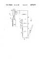
- FIG. 1is an exploded side elevational view of a field terminable modular plug embodying the present invention.
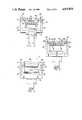
- FIG. 2is a front elevational view of the modular plug with the cover assembly removed therefrom.
- FIG. 3is a rear elevational view of the modular plug.
- FIG. 4is a plan view of the modular plug shown with the cover assembly removed therefrom.
- FIG. 5is a rear elevational view of the modular plug shown with the cover assembly removed therefrom.
- FIG. 6is a sectional view taken generally along the line of 6--6 of FIG. 4.
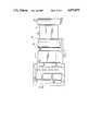
- FIG. 7is a bottom view of the cover assembly.
- FIG. 8is similar to FIG. 4 and further illustrates the arrangement of the contacts.
- a field terminable modular connector or plug embodying the present inventionis indicated generally by the reference numeral 10.
- the illustrated connector 10is an eight conductor line cord plug adapted to be received in mating engagement with a standard FCC telephone plug receptacle. It is particularly adapted to terminate an insulated electrical cable, such as a telecommunication cable containing eight individual solid wire conductors. Such a cable is shown in FIG. 6 and designated by the letter C.
- the connectoris formed by a plurality of individual parts which cooperate during assembly in a manner which will be hereinafter more fully described.
- the parts or sections which comprise the modular connector 10are preferably molded from durable resilient dielectric plastic material and include a hollow body indicated generally at 12, an insert or contact carrier designated generally by the numeral 14 and received within the body, and a cover assembly indicated generally at 16, which includes a cover 15 and a strain relief member 17 and provides a closure for a top opening in the upper rear portion of the body 12 and strain relief for the cable C, as hereinafter further discussed.
- the body section 12has a plugging part at its forward end sized to be received in plugging engagement within a standard FCC telephone plug receptacle.
- the plugging parthas a bottom wall 18, a front wall 20 and side walls 22,22 which extend upwardly from the bottom wall and a top wall 24 which extends rearwardly for some distance from the front wall and terminates approximate the central portion of the body at a transversely disposed and upwardly extending central wall 23.
- the bodyalso has a conductor terminating part which is integrally connected to and extends rearwardly from the plugging part.
- the bottom wall of the conductor terminating partis formed by the rearward extension of the bottom wall 18.
- the conductor receiving parthas a lateral width slightly greater than the lateral width of the plugging part and includes side walls 25,25.
- the width of the conductor terminating partis substantially equal to the width of the plugging part plus the combined major thickness of the two side walls 25,25.
- the body wallscooperate to define a rearwardly and upwardly open body cavity for receiving the contact carrier 14.
- a pair of opposing longitudinally extending lips 29,29project laterally inwardly from the upper edges of the side walls 25,25 as shown in FIGS. 2-5.
- the lips 29,29comprise hook-like projections as viewed from the ends of the modular plug 10 and as best shown in FIGS. 2, 3 and 5.
- the contact carrier 14is configured to be slidably received within the body cavity and is retained in snap-together assembly with the resilient body section 12 by connecting elements 21,21 which project from opposite sides of the contact carrier 14, as shown in FIG. 4, and snap into engagement with upwardly extending and forwardly facing edges of the side walls 25,25.
- An array of longitudinally elongated resilient insulation displacement contacts, equal in number to the conductors to be terminated,are mounted on the front portion of the contact carrier 14.
- the contactsare preferably stamped from flat spring metal and include two groups of contacts, designated generally at 26,26 and 26',26', mounted in laterally spaced apart alternate series on the contact carrier.
- the contacts which comprise the two groupsare of somewhat similar configuration, however the rear or insulation displacement portions of the various contacts, which portions are located within the conductor terminating part of the body 12, are laterally offset from the front portions thereof by varying amounts. It should also be noted that the contacts 26',26' are of somewhat greater longitudinal extent that the contacts 26,26.
- a typical contact 26'has a bifurcated insulation displacement portion 28' which extends through and projects above the contact carrier 14 and defines an upwardly open insulation displacement slot 30', best shown in FIG. 5.
- the illustrated contact 26'further includes a contact portion 32', of somewhat lesser lateral width than the insulation displacement portion 28', integrally connected to the lower end of the insulation displacement portion 28'.
- the contact portion 32'is disposed within a generally complementary groove in the contact carrier 14, extends in a forward direction along the underside of the contact carrier, is reversely bent about the forward end of the contact carrier, and extends rearwardly for some distance along the upper portion of the contact carrier, substantially as shown in FIG. 6.
- the length differential between the contacts of the two groupscause the insulation displacement portions of the contacts which comprise the two groups to be longitudinally staggered, as viewed from above and best shown in FIG. 4.
- This arrangementenables the array of contacts to be closely laterally spaced within the conductor terminating part of the housing to minimize the required width dimension of the connector body 12 so that the modular plug 10 ma be arranged in adjacent side-by-side relationship to other modular plugs of like kind plugged into a multi-plug adapter which comprises an array of closely spaced plug receptacles such as the receptacles 13a-13f shown in U.S. patent application of James J. Johnston entitled Interface Connector, Ser. No. 365,855, filed Apr. 5, 1982, owned by the assignee of the present invention, now abandoned, and hereby adopted by reference as part of the present invention.
- a generally rectangular metal blade 34is mounted in and extends transversely of the contact carrier 14 forward of the insulation displacement portions 28,28 and 28',28'.
- the blade 34has a rectilinear upper edge 36 which is exposed above the contact carrier 14.
- the edge 36is preferably honed smooth but is not sharp, so that accidental contact with the edge when handling the device will not be likely to cause injury.
- An upwardly projecting strain relief ridge 40 formed on the contact carrier 14extends transversely of the contact carrier rearward of the blade 34 and is partially defined by a plurality of longitudinally extending conductor receiving grooves 38,38 formed in the contact carrier 14, as best shown in FIG. 4.
- the grooves 38,38are equal in number to the contacts 26,26' and open through the upper surface of the contact carrier.
- Each groove 38is longitudinally aligned with an associated insulation displacement portion 28 or 28'. It should be noted that the portions of the conductor receiving grooves located forward of the ridge 40 and indicated at 38',38' are somewhat deeper than the portions of the grooves rearward of the ridge, for a purpose which will be hereinafter further evident.
- each recess 42is longitudinally aligned with an associated groove 38', 38'.
- the cover asssembly 16includes the cover 15 adapted for snap-together assembly with the body 12, and the cable strain relief member 17 which is of generally elliptical cross-section and connected to the rear edge of the cover by an elongated flexible strap or living hinge 48.
- the strain relief member 17extends between the side walls 25,25, the opposite end portions of the strain relief member being received within generally complementary upwardly and inwardly opening recesses 50,50 formed in the side walls 25,25, best shown in FIG. 4.
- Latching cams 49,49project from opposite ends of the strain relief member 17 for cooperating in snap engagement with the lips 29,29 to temporarily secure the cover assembly 16 and an associated cable C in assembly with the body 12 until the cover 15 is assembled with the body.
- the strain relief member 17cooperates with an upwardly open recess 54 in the contact carrier to grip and provide strain relief for the cable C terminated by the modular plug 10.
- a shearing member 56 formed on the lower sides of the cover 5extends transversely thereof to define a transversely extending shearing edge 58 which cooperates in shearing relation with the blade edge 36 when the cover 15 is snapped into assembly with the body 12.
- a conductor stuffer 60 defined by a portion of the lower surface of the cover 15extends transversely thereof in rearwardly spaced relation to the shearing member 56 and cooperates with the shearing member to define a downwardly open strain relief recess 62 above the strain relief ridge 40.
- the lower surface of the conductor stuffer 60has a plurality of recesses 64,64 opening therethrough for registry with associated insulation displacement portions 28,28 and 28',28' and receives the upper ends of the latter insulation displacement portions when the cover 15 is assembled in snap-in engagement with the body 12.
- the contact carrier 14is preferably permanently assembled with the body 12 during manufacture.
- the cover assemblyis intended for assembly with the body 12 in the field when the connector assembly 10 is used to terminate an associated cable.
- an end portion of the cable insulation jacketis stripped from the cable to expose end portions of the various individually insulated and color coded conductors which comprise the cable.
- the jacketed end portion of the cableis positioned in overlying relation to the recess 54 in the contact carrier and the strain relief element 17 is snapped into the body 12 with its opposite ends in the recesses 50,50.
- the latching cams 49,49cooperate with the lips 29,29 to temporarily secure the cable C and cover assembly 16 in assembly with the body.
- the color coded conductor free end portionsare then fanned out and each conductor end portion is positioned according to color code within of an associated insulation displacement slot 30 or 30' and in parallel alignment with an associated conductor receiving groove 38.
- the free end portions of the conductorsare further arranged to extend for some distance in a forward direction beyond the blade 34, each conductor free end portion being disposed within an associated conductor receiving groove 42 forward of the blade.
- the cover 15, secured to the strain relief member,is then aligned with the upper edges of the side walls 22,22 and snapped into engagement with the body 12 by applying pressure, as necessary, to complete cable termination. More specifically, as the cover 15 is pivoted into assembly with the body 12 using the strain relief member 17 as a fulcrum, the shearing edge 58 cooperates in shearing relation with the blade edge 36 to snip-off the excess free end portions of the conductors.
- the downwardly facing surface o the conductor stuffer 60simultaneously sets the various conductors in respectively associated insulation displacement slots 30,30 and 30',30' as the insulation displacement portions 28,28 and 28',28' move into the recesses 64,64 formed in the lower side of the cover.
- each insulated conductoris deflected downwardly and away from the blade 34 by the shearing member 56 and into an associated conductor receiving groove 38' immediately forward of the strain relief ridge 40.
- the free ends of the conductorsare also simultaneously bent over the strain relief ridge 40 to an assembled position, substantially as shown in FIG. 6.
- the cable strain relief member 17 at the rear end portion of the bodyis also simultaneously brought into strain relieving engagement with the cable C.
- each conductoris disposed within an associated conductor receiving groove portion 38' and is thereby isolated from each of the other trimmed conductor end portions. Further, the shearing member 56 substantially covers the portion of the blade rear surface which is exposed above the contact carrier 14 so that the risk of electrically shorting the conductors against the blade is entirely eliminated.
- the snap-in cover 15is held in assembly with the body inwardly of the side walls 25,25 12 by the hook shaped projections 29,29 on the body which engage associated surfaces on the cover, designated by the numerals 51,51 in FIG. 3. Provision of the cover 15 and strain relief member 17 as a connected assembly reduces the number of separate small parts which must be handled in terminating a cable, thereby reducing risk of part loss during termination.
- the arrangement of the blade 34 within the housingvirtually eleminates all risk of accidental finger contact with the blade edge during handling. However, should accidental contact occur the relatively dull edge on the blade further assures that no injury is likely to result from such contact.
- the width of the plug connectoris minimized by minimizing the thickness of the walls 25,25 while maintaining sufficient wall thickness to assure snap-together assembly of the various parts of the resilient connector without risk of permanent set and utilizing a staggered arrangement of the insulation displacement portions within the conductor terminating portion of the housing.
- the arrangement of the cover for snap assembly with the body inward of the side walls 25,25also important to the realization of an eight contact modular connector for plugging engagement within a standard FCC modular telephone receptacle and having a minimum width dimension which enables adjacent side-by-side plugging with minimal spacial requirement.
Landscapes
- Coupling Device And Connection With Printed Circuit (AREA)
Abstract
Description
Claims (24)
Priority Applications (4)
| Application Number | Priority Date | Filing Date | Title |
|---|---|---|---|
| US07/101,570US4875875A (en) | 1987-09-28 | 1987-09-28 | Field terminable modular connector |
| EP88308953AEP0310339B1 (en) | 1987-09-28 | 1988-09-27 | Field terminable modular connector |
| DE3889406TDE3889406D1 (en) | 1987-09-28 | 1988-09-27 | Modular connector in a connector panel. |
| EP9393202785AEP0602690A3 (en) | 1987-09-28 | 1988-09-27 | Modular connector in a connection field. |
Applications Claiming Priority (1)
| Application Number | Priority Date | Filing Date | Title |
|---|---|---|---|
| US07/101,570US4875875A (en) | 1987-09-28 | 1987-09-28 | Field terminable modular connector |
Publications (1)
| Publication Number | Publication Date |
|---|---|
| US4875875Atrue US4875875A (en) | 1989-10-24 |
Family
ID=22285347
Family Applications (1)
| Application Number | Title | Priority Date | Filing Date |
|---|---|---|---|
| US07/101,570Expired - LifetimeUS4875875A (en) | 1987-09-28 | 1987-09-28 | Field terminable modular connector |
Country Status (3)
| Country | Link |
|---|---|
| US (1) | US4875875A (en) |
| EP (2) | EP0602690A3 (en) |
| DE (1) | DE3889406D1 (en) |
Cited By (26)
| Publication number | Priority date | Publication date | Assignee | Title |
|---|---|---|---|---|
| US5129840A (en)* | 1990-03-01 | 1992-07-14 | Yazaki Corporation | Electrical connector |
| US5145401A (en)* | 1991-05-28 | 1992-09-08 | Superior Modular Products, Inc. | Electrical connector having improved spring contacts |
| US5181856A (en)* | 1991-01-18 | 1993-01-26 | Bayer Aktiengesellschaft | Cable plug for spark plugs |
| US5295869A (en)* | 1992-12-18 | 1994-03-22 | The Siemon Company | Electrically balanced connector assembly |
| US5427544A (en)* | 1992-09-25 | 1995-06-27 | Yazaki Corporation | Press-connecting terminal and connector using same |
| US5459643A (en)* | 1993-09-30 | 1995-10-17 | The Siemon Company | Electrically enhanced wiring block with break test capability |
| US5505638A (en)* | 1994-11-18 | 1996-04-09 | Su; Gorden | Telephone plug module |
| US5554053A (en)* | 1994-08-24 | 1996-09-10 | Minnesota Mining And Manufacturing Company | Modular connector with separable wire retention |
| US5593315A (en)* | 1994-03-31 | 1997-01-14 | Japan Aviation Electronics Industry, Limited | Connector readily assembled with a cable accurately positioned without using tools |
| WO1997004504A1 (en)* | 1995-07-14 | 1997-02-06 | Augat Inc. | Squib connector for automotive air bag assembly |
| WO1998000887A1 (en)* | 1996-07-01 | 1998-01-08 | Siemens Aktiengesellschaft | Plug-in connector with closable cover piece and method of connecting a lead wire to such a plug-in connector |
| US5882224A (en)* | 1996-08-28 | 1999-03-16 | Thomas & Betts International, Inc. | Squib connector socker assembly having shorting clip for automotive air bags |
| US5882222A (en)* | 1996-07-16 | 1999-03-16 | Hirose Electric Co., Ltd. | Electrical connector |
| US5961340A (en)* | 1997-03-14 | 1999-10-05 | Reltec Corporation | Wire trimmer |
| US5975936A (en)* | 1997-09-03 | 1999-11-02 | Lucent Technologies Inc. | Blade carrier for use in a communication plug |
| US6010371A (en)* | 1997-04-24 | 2000-01-04 | Abbott Laboratories | Electrical connector |
| US6019645A (en)* | 1997-12-23 | 2000-02-01 | Molex Incorporated | Electrical connector assembly with terminal position assurance device |
| WO2000013265A1 (en)* | 1998-08-28 | 2000-03-09 | Barnes Wentworth | Rj45 connector |
| US6247959B1 (en)* | 1999-09-15 | 2001-06-19 | Avaya Technology Corp. | Modular plug assembly |
| US6520794B2 (en)* | 2000-11-29 | 2003-02-18 | Sheng Hsin Liao | Receptacle having structure conveniently in assembly |
| US6551125B2 (en)* | 1998-11-13 | 2003-04-22 | Mitsumi Electric Co., Ltd. | Connecting structure for a portable electronic device cord |
| US6558185B1 (en) | 2000-05-02 | 2003-05-06 | Dekko Engineering, Inc. | Jumper cable plug |
| US20060057884A1 (en)* | 2004-09-15 | 2006-03-16 | Xavier Fasce | Connector assembly for housing insulation displacement elements |
| US20060160404A1 (en)* | 2004-09-15 | 2006-07-20 | Alarcon Sergio A | Connector assembly for housing insulation displacement elements |
| US7458840B2 (en)* | 2004-09-15 | 2008-12-02 | 3M Innovative Properties Company | Cap configured to removably connect to an insulation displacement connector block |
| US20140187077A1 (en)* | 2010-10-21 | 2014-07-03 | Panduit Corp. | Communication plug with improved crosstalk |
Families Citing this family (5)
| Publication number | Priority date | Publication date | Assignee | Title |
|---|---|---|---|---|
| GB8924898D0 (en)* | 1989-11-03 | 1989-12-20 | Commtel Consumer Electronics P | Telephone extension socket |
| US5514007A (en)* | 1994-05-04 | 1996-05-07 | Thomas & Betts Corporation | Data connector strain relief assembly |
| EP0683548B1 (en)* | 1994-05-19 | 1998-07-29 | Multi-Contact Ag | Electrical connector having cable strain relief |
| US7101216B2 (en) | 2004-09-15 | 2006-09-05 | 3M Innovative Properties Company | Insulation displacement system for two electrical conductors |
| JP4895725B2 (en)* | 2006-08-25 | 2012-03-14 | スリーエム イノベイティブ プロパティズ カンパニー | IDC connector |
Citations (15)
| Publication number | Priority date | Publication date | Assignee | Title |
|---|---|---|---|---|
| US2673968A (en)* | 1949-11-25 | 1954-03-30 | Leviton Mfg Company | Self-piercing electrical connector plug |
| US2802083A (en)* | 1956-09-04 | 1957-08-06 | James M Lapeyre | Self-connecting circuit interruptor devices |
| US3596232A (en)* | 1967-12-29 | 1971-07-27 | Joseph Medley | Electrical connectors |
| US3708779A (en)* | 1969-05-12 | 1973-01-02 | Minnesota Mining & Mfg | Wire-splicing apparatus and method |
| US4023879A (en)* | 1975-10-20 | 1977-05-17 | A.P. Products Incorporated | Adjustable electrical connector with replaceable contact sub-assembly and variable strain relief |
| US4109991A (en)* | 1974-05-10 | 1978-08-29 | E. I. Du Pont De Nemours And Company | Self-stripping electrical connector and terminal |
| US4194803A (en)* | 1978-05-15 | 1980-03-25 | Pintek, Inc. | Connector for flat ribbon cable |
| US4195898A (en)* | 1977-12-27 | 1980-04-01 | Bunker Ramo Corporation | Patchcord connector |
| US4444448A (en)* | 1980-01-14 | 1984-04-24 | Minnesota Mining And Manufacturing Company | Wire cutting electrical connector |
| US4444474A (en)* | 1982-01-25 | 1984-04-24 | Pasko Edward H | Stationary eyepiece telescope |
| US4444449A (en)* | 1981-03-16 | 1984-04-24 | Minnesota Mining And Manufacturing Company | Electrical connector |
| US4496206A (en)* | 1982-05-24 | 1985-01-29 | Minnesota Mining And Manufacturing Company | Side entry electrical wire connector |
| US4522459A (en)* | 1981-12-17 | 1985-06-11 | At&T Technologies, Inc. | Systems for and methods of making electrical connections |
| US4545635A (en)* | 1983-10-19 | 1985-10-08 | Amp Incorporated | Matrix connector |
| US4723915A (en)* | 1985-07-01 | 1988-02-09 | Brand-Rex Company | Terminal assembly having conductor stuffer |
Family Cites Families (8)
| Publication number | Priority date | Publication date | Assignee | Title |
|---|---|---|---|---|
| US3699498A (en)* | 1970-04-30 | 1972-10-17 | Bell Telephone Labor Inc | Devices for making electrical connections |
| US3835445A (en)* | 1972-12-04 | 1974-09-10 | Western Electric Co | Electrical connecting devices for terminating cords and methods of assembling the devices to cords |
| US3860316A (en)* | 1973-07-06 | 1975-01-14 | Western Electric Co | Electrical connecting devices for terminating cords and methods of assembling the devices to cords |
| US4261633A (en)* | 1979-08-27 | 1981-04-14 | Amp Incorporated | Wiring module for telephone jack |
| DE3200213A1 (en)* | 1981-04-04 | 1982-10-21 | Krone Gmbh, 1000 Berlin | Core connector for telecommunications cables |
| WO1983003717A1 (en)* | 1982-04-05 | 1983-10-27 | Akzona Inc | Interface connector |
| US4516822A (en)* | 1984-02-27 | 1985-05-14 | Amp Incorporated | Round cable adaptor for modular plug |
| DE3711675A1 (en)* | 1987-04-07 | 1988-10-27 | Krone Ag | CORE CONNECTOR FOR CABLE CORDS, ESPECIALLY TELECOMMUNICATION CABLES |
- 1987
- 1987-09-28USUS07/101,570patent/US4875875A/ennot_activeExpired - Lifetime
- 1988
- 1988-09-27EPEP9393202785Apatent/EP0602690A3/ennot_activeWithdrawn
- 1988-09-27EPEP88308953Apatent/EP0310339B1/ennot_activeExpired - Lifetime
- 1988-09-27DEDE3889406Tpatent/DE3889406D1/ennot_activeExpired - Lifetime
Patent Citations (16)
| Publication number | Priority date | Publication date | Assignee | Title |
|---|---|---|---|---|
| US2673968A (en)* | 1949-11-25 | 1954-03-30 | Leviton Mfg Company | Self-piercing electrical connector plug |
| US2802083A (en)* | 1956-09-04 | 1957-08-06 | James M Lapeyre | Self-connecting circuit interruptor devices |
| US3596232A (en)* | 1967-12-29 | 1971-07-27 | Joseph Medley | Electrical connectors |
| US3708779B1 (en)* | 1969-05-12 | 1983-07-12 | ||
| US3708779A (en)* | 1969-05-12 | 1973-01-02 | Minnesota Mining & Mfg | Wire-splicing apparatus and method |
| US4109991A (en)* | 1974-05-10 | 1978-08-29 | E. I. Du Pont De Nemours And Company | Self-stripping electrical connector and terminal |
| US4023879A (en)* | 1975-10-20 | 1977-05-17 | A.P. Products Incorporated | Adjustable electrical connector with replaceable contact sub-assembly and variable strain relief |
| US4195898A (en)* | 1977-12-27 | 1980-04-01 | Bunker Ramo Corporation | Patchcord connector |
| US4194803A (en)* | 1978-05-15 | 1980-03-25 | Pintek, Inc. | Connector for flat ribbon cable |
| US4444448A (en)* | 1980-01-14 | 1984-04-24 | Minnesota Mining And Manufacturing Company | Wire cutting electrical connector |
| US4444449A (en)* | 1981-03-16 | 1984-04-24 | Minnesota Mining And Manufacturing Company | Electrical connector |
| US4522459A (en)* | 1981-12-17 | 1985-06-11 | At&T Technologies, Inc. | Systems for and methods of making electrical connections |
| US4444474A (en)* | 1982-01-25 | 1984-04-24 | Pasko Edward H | Stationary eyepiece telescope |
| US4496206A (en)* | 1982-05-24 | 1985-01-29 | Minnesota Mining And Manufacturing Company | Side entry electrical wire connector |
| US4545635A (en)* | 1983-10-19 | 1985-10-08 | Amp Incorporated | Matrix connector |
| US4723915A (en)* | 1985-07-01 | 1988-02-09 | Brand-Rex Company | Terminal assembly having conductor stuffer |
Cited By (36)
| Publication number | Priority date | Publication date | Assignee | Title |
|---|---|---|---|---|
| US5129840A (en)* | 1990-03-01 | 1992-07-14 | Yazaki Corporation | Electrical connector |
| US5181856A (en)* | 1991-01-18 | 1993-01-26 | Bayer Aktiengesellschaft | Cable plug for spark plugs |
| US5145401A (en)* | 1991-05-28 | 1992-09-08 | Superior Modular Products, Inc. | Electrical connector having improved spring contacts |
| WO1992022106A1 (en)* | 1991-05-28 | 1992-12-10 | Superior Modular Products, Inc. | Electrical connector having improved spring contacts |
| US5427544A (en)* | 1992-09-25 | 1995-06-27 | Yazaki Corporation | Press-connecting terminal and connector using same |
| US5474474A (en)* | 1992-12-18 | 1995-12-12 | The Siemon Company | Electrically balanced connector assembly |
| US5295869A (en)* | 1992-12-18 | 1994-03-22 | The Siemon Company | Electrically balanced connector assembly |
| US5362254A (en)* | 1992-12-18 | 1994-11-08 | The Siemon Company | Electrically balanced connector assembly |
| US5435752A (en)* | 1992-12-18 | 1995-07-25 | The Siemon Company | Electrically balanced connector assembly |
| US5459643A (en)* | 1993-09-30 | 1995-10-17 | The Siemon Company | Electrically enhanced wiring block with break test capability |
| US5593315A (en)* | 1994-03-31 | 1997-01-14 | Japan Aviation Electronics Industry, Limited | Connector readily assembled with a cable accurately positioned without using tools |
| US5554053A (en)* | 1994-08-24 | 1996-09-10 | Minnesota Mining And Manufacturing Company | Modular connector with separable wire retention |
| US5505638A (en)* | 1994-11-18 | 1996-04-09 | Su; Gorden | Telephone plug module |
| WO1997004504A1 (en)* | 1995-07-14 | 1997-02-06 | Augat Inc. | Squib connector for automotive air bag assembly |
| US5616045A (en)* | 1995-07-14 | 1997-04-01 | Augat Inc. | Squib connector for automotive air bag assembly |
| US5746618A (en)* | 1995-07-14 | 1998-05-05 | Augat Inc. | Squib connector for automotive air bag assembly |
| WO1998000887A1 (en)* | 1996-07-01 | 1998-01-08 | Siemens Aktiengesellschaft | Plug-in connector with closable cover piece and method of connecting a lead wire to such a plug-in connector |
| US5882222A (en)* | 1996-07-16 | 1999-03-16 | Hirose Electric Co., Ltd. | Electrical connector |
| US6145193A (en)* | 1996-08-28 | 2000-11-14 | Thomas & Betts International, Inc. | Method of forming a squib connector socket assembly having shorting clip for automotive air bags |
| US5882224A (en)* | 1996-08-28 | 1999-03-16 | Thomas & Betts International, Inc. | Squib connector socker assembly having shorting clip for automotive air bags |
| US5961340A (en)* | 1997-03-14 | 1999-10-05 | Reltec Corporation | Wire trimmer |
| US6010371A (en)* | 1997-04-24 | 2000-01-04 | Abbott Laboratories | Electrical connector |
| US5975936A (en)* | 1997-09-03 | 1999-11-02 | Lucent Technologies Inc. | Blade carrier for use in a communication plug |
| US6019645A (en)* | 1997-12-23 | 2000-02-01 | Molex Incorporated | Electrical connector assembly with terminal position assurance device |
| WO2000013265A1 (en)* | 1998-08-28 | 2000-03-09 | Barnes Wentworth | Rj45 connector |
| US6551125B2 (en)* | 1998-11-13 | 2003-04-22 | Mitsumi Electric Co., Ltd. | Connecting structure for a portable electronic device cord |
| US6247959B1 (en)* | 1999-09-15 | 2001-06-19 | Avaya Technology Corp. | Modular plug assembly |
| US6558185B1 (en) | 2000-05-02 | 2003-05-06 | Dekko Engineering, Inc. | Jumper cable plug |
| US6520794B2 (en)* | 2000-11-29 | 2003-02-18 | Sheng Hsin Liao | Receptacle having structure conveniently in assembly |
| US20060057884A1 (en)* | 2004-09-15 | 2006-03-16 | Xavier Fasce | Connector assembly for housing insulation displacement elements |
| US20060160404A1 (en)* | 2004-09-15 | 2006-07-20 | Alarcon Sergio A | Connector assembly for housing insulation displacement elements |
| US7335049B2 (en) | 2004-09-15 | 2008-02-26 | 3M Innovative Properties Company | Connector assembly for housing insulation displacement elements |
| US7399197B2 (en)* | 2004-09-15 | 2008-07-15 | 3M Innovative Properties Company | Connector assembly for housing insulation displacement elements |
| US7458840B2 (en)* | 2004-09-15 | 2008-12-02 | 3M Innovative Properties Company | Cap configured to removably connect to an insulation displacement connector block |
| US20140187077A1 (en)* | 2010-10-21 | 2014-07-03 | Panduit Corp. | Communication plug with improved crosstalk |
| US9595771B2 (en)* | 2010-10-21 | 2017-03-14 | Panduit Corp. | Communication plug with improved crosstalk |
Also Published As
| Publication number | Publication date |
|---|---|
| EP0310339A2 (en) | 1989-04-05 |
| DE3889406D1 (en) | 1994-06-09 |
| EP0602690A3 (en) | 1994-08-31 |
| EP0310339B1 (en) | 1994-05-04 |
| EP0602690A2 (en) | 1994-06-22 |
| EP0310339A3 (en) | 1990-05-23 |
Similar Documents
| Publication | Publication Date | Title |
|---|---|---|
| US4875875A (en) | Field terminable modular connector | |
| US4566749A (en) | Electrical connector receptacle | |
| US4343528A (en) | Modular interconnect system | |
| US5634817A (en) | Patch connector | |
| US4053197A (en) | Electrical connector | |
| US4317608A (en) | Slotted pate terminal for stranded wire | |
| US6368148B1 (en) | Ribbon cable connector with ground bus | |
| US4138184A (en) | Terminating means for a multi-wire cable | |
| US4367005A (en) | Strain relief cover | |
| US4648678A (en) | Electrical connector | |
| GB1559572A (en) | Electrical connectors | |
| CA1236539A (en) | Electrical plug assembly with cable guiding member | |
| US4538874A (en) | Modular jack assembly | |
| EP0102798B1 (en) | Cable clamp for an electrical connector | |
| US5133672A (en) | Insulation displacement terminal | |
| CA1190295A (en) | Electrical termination system and connector member | |
| US4373766A (en) | Electrical connector assembly | |
| US4488768A (en) | Programmable electrical connector | |
| US5659948A (en) | Termination tool for modular telephone connector | |
| US5464352A (en) | Electrical connector assembly | |
| EP0203365A2 (en) | Electrical connector assembly and method for terminating cable | |
| US4909753A (en) | Patch connector | |
| AU2202095A (en) | Electrical connector with integral shorting assembly | |
| USRE32810E (en) | Electrical contact for terminating insulated conductors | |
| GB2080032A (en) | A plug for masking switching contacts |
Legal Events
| Date | Code | Title | Description |
|---|---|---|---|
| AS | Assignment | Owner name:BRINTEC CORPORATION, WILLIMANTIC, CT. A CORP. OF D Free format text:ASSIGNMENT OF ASSIGNORS INTEREST.;ASSIGNORS:ARCHER, LEE A.;BROWNELL, KENNETH W. JR.;REEL/FRAME:004814/0738 Effective date:19871119 | |
| STCF | Information on status: patent grant | Free format text:PATENTED CASE | |
| AS | Assignment | Owner name:BRINTEC SYSTEMS CORPORATION, 1600 WEST MAIN STREET Free format text:ASSIGNMENT OF ASSIGNORS INTEREST.;ASSIGNOR:BRINTEO CORPORATION, A DE CORP.;REEL/FRAME:005481/0657 Effective date:19900710 | |
| AS | Assignment | Owner name:HUBBELL PREMISE PRODUCTS, INC., A CORP. OF DE, CO Free format text:ASSIGNMENT OF ASSIGNORS INTEREST.;ASSIGNOR:BEINTEC SYSTEMS CORPORATION, A CORP. OF DE;REEL/FRAME:005600/0744 Effective date:19900712 | |
| AS | Assignment | Owner name:HUBBELL INCORPORATED, 584 DERBY MILFORD ROAD, ORAN Free format text:ASSIGNMENT OF ASSIGNORS INTEREST.;ASSIGNOR:HUBBELL PREMISE PRODUCTS, INC., A CORP. OF DE;REEL/FRAME:005673/0169 Effective date:19900405 | |
| FEPP | Fee payment procedure | Free format text:PAYOR NUMBER ASSIGNED (ORIGINAL EVENT CODE: ASPN); ENTITY STATUS OF PATENT OWNER: LARGE ENTITY | |
| FPAY | Fee payment | Year of fee payment:4 | |
| FPAY | Fee payment | Year of fee payment:8 | |
| FPAY | Fee payment | Year of fee payment:12 |