US4875757A - Optical cable - Google Patents
Optical cableDownload PDFInfo
- Publication number
- US4875757A US4875757AUS07/196,525US19652588AUS4875757AUS 4875757 AUS4875757 AUS 4875757AUS 19652588 AUS19652588 AUS 19652588AUS 4875757 AUS4875757 AUS 4875757A
- Authority
- US
- United States
- Prior art keywords
- tube
- cable
- filaments
- fibers
- fiber
- Prior art date
- Legal status (The legal status is an assumption and is not a legal conclusion. Google has not performed a legal analysis and makes no representation as to the accuracy of the status listed.)
- Expired - Fee Related
Links
Images

Classifications
- G—PHYSICS
- G02—OPTICS
- G02B—OPTICAL ELEMENTS, SYSTEMS OR APPARATUS
- G02B6/00—Light guides; Structural details of arrangements comprising light guides and other optical elements, e.g. couplings
- G02B6/44—Mechanical structures for providing tensile strength and external protection for fibres, e.g. optical transmission cables
- G02B6/4401—Optical cables
- G02B6/4402—Optical cables with one single optical waveguide
- G—PHYSICS
- G02—OPTICS
- G02B—OPTICAL ELEMENTS, SYSTEMS OR APPARATUS
- G02B6/00—Light guides; Structural details of arrangements comprising light guides and other optical elements, e.g. couplings
- G02B6/02—Optical fibres with cladding with or without a coating
- G02B6/02395—Glass optical fibre with a protective coating, e.g. two layer polymer coating deposited directly on a silica cladding surface during fibre manufacture
- G—PHYSICS
- G02—OPTICS
- G02B—OPTICAL ELEMENTS, SYSTEMS OR APPARATUS
- G02B6/00—Light guides; Structural details of arrangements comprising light guides and other optical elements, e.g. couplings
- G02B6/44—Mechanical structures for providing tensile strength and external protection for fibres, e.g. optical transmission cables
- G02B6/4401—Optical cables
- G02B6/4429—Means specially adapted for strengthening or protecting the cables
- G02B6/4434—Central member to take up tensile loads
- G—PHYSICS
- G02—OPTICS
- G02B—OPTICAL ELEMENTS, SYSTEMS OR APPARATUS
- G02B6/00—Light guides; Structural details of arrangements comprising light guides and other optical elements, e.g. couplings
- G02B6/44—Mechanical structures for providing tensile strength and external protection for fibres, e.g. optical transmission cables
- G02B6/4401—Optical cables
- G02B6/4429—Means specially adapted for strengthening or protecting the cables
- G02B6/44384—Means specially adapted for strengthening or protecting the cables the means comprising water blocking or hydrophobic materials
- G—PHYSICS
- G02—OPTICS
- G02B—OPTICAL ELEMENTS, SYSTEMS OR APPARATUS
- G02B6/00—Light guides; Structural details of arrangements comprising light guides and other optical elements, e.g. couplings
- G02B6/44—Mechanical structures for providing tensile strength and external protection for fibres, e.g. optical transmission cables
- G02B6/4479—Manufacturing methods of optical cables
- G02B6/449—Twisting
Definitions
- This inventionrelates to optical cable.
- Optical cableshave certain common elements. These include at least one optical fiber for transmission purposes, means for protecting the fiber from damage, and a jacket which provides the outer layer of the cable.
- optical fibersare housed in grooves formed in the outer surface of a central support member, the grooves extending around the member either helically in one direction or alternately, in each direction around the member.
- an optical fiber or fibersis housed within a plastic tube located coaxially of the cable.
- These tubesare normally provided for the sole purpose of forming a passage for the fibers and any protection to prevent crushing of the cable and thus of the fibers is provided by a compression resistant shield which surrounds the fiber carrying tube.
- an optical fiberhas a reinforced plastic coating surrounding it. This is described in a paper entitled "New Applications of Pultrusion Technology RP Covered Optical Fiber" by K. Fuse and Y. Shirasaka and read before the 40th Annual Conference in January 1985 of Reinforced Plastics/Composites Institute, The Society of the Plastics Industry Inc.
- an optical fiberis surrounded by a buffer material and then enclosed within a tube of reinforced plastics by a manufacturing process referred to as pultrusion.
- reinforcing fibersare coated with a resin and the coated fibers and the pre-buffered optical fiber are passed through a die with the optical fiber located centrally so that the resin on the reinforcing fibers merges to form the plastic coating.
- an optical cablehaving a core and a jacket, the core comprising at least on optical fiber and a protective tube immediately surrounding and housing the optical fiber, the tube having an inner diameter greater than the diameter of the fiber whereby the fiber is loosely contained by the tube and the tube comprises matrix of glass filaments with interstices between adjacent filaments filled with a rigid material holding the filaments in their relative positions in which the filaments extend side-by-side longitudinally of the tube.
- the optical fiberis loosely contained within the protective tube so as to enable relative longitudinal movement of optical fiber and tube during flexing or bending of the cable while axial tension is not placed upon the fiber by the surface of the tube.
- the protective tube in the construction of the inventionhas mechanical properties for protecting the optical fiber which are superior to those offered by a conventional protective tube.
- protective tubesare formed from plastics which provide an inadequate tensile strength to protect the optical fibers against tensile loadings.
- some other method of providing the necessary tensile strengthis required such as steel filaments extending longitudinally of the cable and lying exteriorly of the tubes. It is normal to provide the steel filaments in a jacket surrounding a protective tube or tubes.
- a steel sheath around a core of protective tubesmay also provide the required tensile strength.
- each longitudinally extending glass filament in the tube immediately surrounding the optical fiberis a tensile strength member.
- a protective tube of relatively small diameter in the cable of the inventionmay have a tensile strength comparable to and possibly exceeding the tensile strength of an optical cable of much larger diameter having a protective tube for optical fibers and steel strength members lying outside the tube, e.g. within the jacket.
- an elastomeric jacketmay be provided around a tube in the cable of the present invention, it follows that no tensile strength members are required either within the jacket or in any other location outside the tube.
- the cablemay consist of at least one optical fiber loosely contained within the protective tube having an outside diameter as small as 4.10 mm and an inside diameter of 1.70 mm.
- the protective tube of the inventive optical cablethere is preferably at least 70% of the tube volume in the form of glass filaments with the rigid material between the interstices providing the remainder of the tube volume.
- the glass filamentsoccupies approximately 80% by volume of the protective tube and the rigid material occupies approximately 20% by volume.
- the rigid material in the tubeis preferably a thermosetting material such as a polyester or epoxy resin.
- the inside of the protective tube unoccupied by the optical fiberis filled with a water blocking medium.
- This water blocking mediummay be a viscous water blocking medium or is preferably a thixotropic water blocking medium.
- FIG. 1is an isometric view of part of a cable according to the embodiment
- FIG. 2is a cross-sectional view taken along the axis of the cable and on a larger scale than FIG. 1;
- FIG. 3is a cross-sectional view of the cable taken along line III--III in FIG. 2;
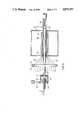
- FIG. 4is a diagrammatic side elevational view of apparatus according to the invention for making the cable of FIGS. 1 and 2;
- FIG. 5is a view similar to FIG. 3 of a part of the apparatus on a larger scale.
- an optical cable 10has a core 12 comprising a plurality of optical fibers 14 housed within a protective tube 16.
- the coreis surrounded by a dielectric jacket 18 which may be, for instance, a polyethylene based material.
- the optical fibers 14have diameters substantially less than the inside diameter of the tube whereby the fibers are loosely contained within the tube even though there may be ten or more fibers in the cable.
- the cable construction of this embodimentdoes not require a cable sheath or shield to protect the optical fibers as the tube 16 is capable of withstanding substantial tensile loads with insignificant strain. For the same reason, no tensile strength member outside the tube 16, such as steel filaments in the jacket are required. In the particular construction shown in FIG. 1, the cable is capable of being subjected to a tensile load of 600 lbs. while the tube 16 satisfactorily protects the fibers from such loading.
- the outside diameter of the cable of the embodimentis 6.5 mm and the tube, which acts as the strength member, has an outside diameter of 4.1 mm and an inside diameter of 1.7 mm.
- the tube 16comprises a plurality of side-by-side and closely packed tensile glass filaments 20 which extend longitudinally of the tube and are embedded within a continuous solidified rigid carrier material 22 which occupy gaps between the filaments 20.
- the glass filaments 20occupy at least 70% and preferably 80% by volume of the tube 16 with the remainder of the tube volume occupied by the carrier materials.
- This rigid carrier materialis a polystyrene or polyester based resin.
- the tensile glass filaments 20lie in close side-by-side positions while extending longitudinally of the tube.
- the tubeis capable of withstanding up to 600 lbs. tensile load, as has been indicated, and with a minimum strain which prevents tensile loads acting directly upon the fibers themselves.
- the tubealso forms the tensile strength member of the cable, it is unnecessary to provide the cable with a metal sheath for tensile purposes or to provide tensile strength members such as steel filaments. Hence, the tube is simply surrounded by the jacket 18 which is provided solely to protect the tube from outside environmental conditions. Otherwise the jacket is not required.
- the tensile glass filaments 20extend substantially longitudinally of the tube so as to resist any extension of the cable caused by tensile loading such as may occur during bending or twisting of the cable as it is being installed or after installation.
- the tensile glass filamentsare provided by, for instance, twenty-four groups of fibers with the groups closely positioned together and, in each group, there are a plurality of strands or rovings of the glass filaments.
- the passage in the center of the tube 12is filled by the optical fibers and a thixotropic water blocking medium which fills any spaces not occupied by the fibers.
- the cableis made by the in-line apparatus shown in FIGS. 4 and 5.
- the apparatuscomprises a reservoir 24 holding a bath 26 of the polystyrene or polyester based resin. Downstream along a passline for the groups of tensile glass filaments 20 is disposed a tube forming means 28.
- This tube forming meanscomprises a tubular guide means in the form of a stainless steel tube 30 which extends along the passline of the glass fibers and has a polished outer surface.
- a heating means 32Surrounding a downstream end portion of the tube 30 is a heating means 32 which comprises a housing 34 shrouding heating elements 36 which may be electrical.
- the housing 34has an inner cylindrical surface 38 which is polished and surrounds the downstream end portion of tube 30 while being spaced from it to define a tubular space 40 between the heating element and the tube 30.
- Guide meansis provided for holding the tensile glass filaments 20 in laterally spaced relationship as they pass through the reservoir 24, for disposing these groups of filaments in spaced apart positions around an arc concentric with the tube 30 and also for causing convergence of the groups of coated glass filaments towards an upstream inlet end 42 of the tubular space 40 to bring the groups of filaments into close relationship as they enter the space.
- This guide meanscomprises a plurality of side-by-side guide pulleys 44, one pulley for each of the groups of tensile filaments. In FIG. 4 only one of the guide pulleys 44 is shown as the guide pulleys 44 for all filament groups are in alignment in that Figure.
- the guide meansalso comprises a circular guide plate 52 through which the tube 30 passes at an upstream end portion of the tube.
- the guide plate 52has a plurality of guide holes 54, i.e. one for each of the groups of tensile filaments and these holes are spaced apart around a pitch circle coinciding with the axis of the tube 30 in equally spaced positions around that axis.
- the guide meansalso comprises a leading chamfered edge 56 of the housing 34 (see FIG. 5) for smoothly contacting the tensile filaments as they move into the space 40.
- the apparatusalso comprises a means for introducing the water blocking thixotropic medium into the crush resistant tube 16.
- This meanscomprises an applicator 56 which comprises a housing mounted at the upstream end of the tube 30.
- the housing 56defines passageways 58 from an inlet 60 to an outlet 62 of the housing to enable the thixotropic medium to be pumped through the inlet 60 from a source not shown, through the passages and out of the housing into the inlet of the tube 30.
- a pump 64(see FIG. 5) is provided for pressurizing the thixotropic medium so that it is forced along the tube 30.
- the pump 64is adjustable in speed to alter the pressure for a reason to be discussed below.
- a concentric inlet tube 66for admittance of the optical fibers 14 to enable the fibers to be fed into the tube 16 during its formation, as will now be described.
- the groups of tensile glass filaments 20are mounted respectively upon individual reels 68 upstream of the reservoir 24. Also at the upstream end of the apparatus are disposed a plurality of spools 70, each spool wound with one of the optical fibers 14.
- the groups of tensile glass filaments 20are fed around their respective pulleys 44, 46, 48 and 50. As the groups of filaments are passed through the bath 26, each individual glass filament becomes coated with the resin which is at room temperature. The groups of filaments then proceed from the bath around the pulley 50, and around any additional guiding pulleys which are required (not shown) to bring the groups through individual holes 54 in the guide plate 52 and form them into a circular array surrounding the tube 30.
- the groupsthen are caused to converge towards each other and towards the tube 30 so as to guide them into the tubular space 40.
- the groups of filamentsenter the tubular space 40, they lie in close relationship and the space 40 becomes filled with the filaments and the resin coating material which surrounds them.
- the glass filaments and resinare drawn along their passlines and through space 40 by a cable reeler 71 and are caused to be molded within the space 40 into the solidified fiberglass tube 16 by the heating means 32 operating at the required temperature, in this case approximately 300° F., to solidify the resin before it leaves the space.
- the completely solidified tubethus moves downstream from within the heater 32.
- the fibers 14are passed from the spool 70 through the tube 66 and device 56 and into the entrance of the tube 30 as shown in FIG. 5.
- the thixotropic water blocking mediumis passed into the passage 58 of the device 56 by the pump 64 so that it surrounds the fibers 14 and is forced in a downstream direction along the tube 30 and, upon leaving this tube, enters into the solidified tube 16.
- the flow of the thixotropic mediumdraws the optical fibers 14 from their spools 70 so as to move them into the tube 16 as the core is being manufactured.
- the coreis completely filled by the optical fibers and the water blocking medium.
- each of the optical fibershas a greater axial length than the tube 16 into which it is being fed so that any bending of the tube 16, in use of the finished cable will merely tend to cause relative axial movement of the tube and fibers in the vicinity of the bend without placing the fibers in tension.
- the pressure placed upon the filling mediumis changeable by altering the speed of the pump 64 so that an increased flow of the medium will draw the optical fibers from their spools at a greater rate.
- This drawing actionforces the optical fibers along the tube 30 at a greater speed than that of the tensile filaments through the space 40, whereby upon the optical fibers and water blocking medium emerging into the tube 16 at the downstream end of the guide means 30, the speed of the optical fibers and of the filling medium is reduced.
- the degree of this meanderingmay be controlled by the changing of the speed of the pump 64.
- the cable structureis relatively simple in construction and avoids the necessity of using steel reinforcing members or a shield surrounding the fiberglass protective tube 16 for protection of the optical fibers during normal tensile loading conditions. It has been shown that the protective tube 16, because of its structure, is capable of withstanding significant tensile loads while protecting the optical fibers.
- the tube 16has an inside diameter which is far in excess of that of the combined diameter of the optical fibers so that each of the fibers are radially movable within the tube.
- the optical fibershave axial lengths which are greater than that of the protective tube 16 whereby tensile loads placed upon the tube and finished cable which tend to stretch the cable will merely tend to straighten the fibers, as described, without placing them into tensile loaded conditions.
Landscapes
- Physics & Mathematics (AREA)
- General Physics & Mathematics (AREA)
- Optics & Photonics (AREA)
- Engineering & Computer Science (AREA)
- Manufacturing & Machinery (AREA)
- Light Guides In General And Applications Therefor (AREA)
Abstract
Description
Claims (6)
Priority Applications (1)
| Application Number | Priority Date | Filing Date | Title |
|---|---|---|---|
| US07/196,525US4875757A (en) | 1986-06-20 | 1988-05-20 | Optical cable |
Applications Claiming Priority (2)
| Application Number | Priority Date | Filing Date | Title |
|---|---|---|---|
| CA000511890ACA1267527A (en) | 1986-06-20 | 1986-06-20 | Optical cable manufacture |
| US07/196,525US4875757A (en) | 1986-06-20 | 1988-05-20 | Optical cable |
Related Parent Applications (1)
| Application Number | Title | Priority Date | Filing Date |
|---|---|---|---|
| US06/877,064Continuation-In-PartUS4763982A (en) | 1986-06-20 | 1986-06-23 | Optical cable manufacture |
Publications (1)
| Publication Number | Publication Date |
|---|---|
| US4875757Atrue US4875757A (en) | 1989-10-24 |
Family
ID=25671030
Family Applications (1)
| Application Number | Title | Priority Date | Filing Date |
|---|---|---|---|
| US07/196,525Expired - Fee RelatedUS4875757A (en) | 1986-06-20 | 1988-05-20 | Optical cable |
Country Status (1)
| Country | Link |
|---|---|
| US (1) | US4875757A (en) |
Cited By (19)
| Publication number | Priority date | Publication date | Assignee | Title |
|---|---|---|---|---|
| US5097526A (en)* | 1989-12-07 | 1992-03-17 | Alcatel N.V. | Connector for two optical cables |
| US5113468A (en)* | 1990-03-14 | 1992-05-12 | Smiths Industries Public Limited Company | Fibre-optic cable assemblies |
| US5157752A (en)* | 1991-10-24 | 1992-10-20 | Northern Telecom Limited | Optical fiber cable with intermingled water blocking means and method of making same |
| US5561729A (en)* | 1995-05-15 | 1996-10-01 | Siecor Corporation | Communications cable including fiber reinforced plastic materials |
| WO1996042028A1 (en)* | 1995-06-12 | 1996-12-27 | Nk Cables Oy | Optical cable |
| US6041153A (en)* | 1998-07-01 | 2000-03-21 | Alcatel | Continuous composite reinforced buffer tubes for optical fiber cables |
| US20040076387A1 (en)* | 2002-10-17 | 2004-04-22 | Alcatel | Fiber optic tube and method of forming a fiber optic tube from a tape |
| US20060159407A1 (en)* | 2005-01-18 | 2006-07-20 | Adc Telecommunications, Inc. | Low shrink telecommunications cable and methods for manufacturing the same |
| US20080290278A1 (en)* | 2002-02-26 | 2008-11-27 | Uni-Pixel Displays, Inc. | Visible plus non-visible field sequential color |
| US20090297102A1 (en)* | 2008-05-28 | 2009-12-03 | Adc Telecommunications, Inc. | Fiber optic cable for connectorization and method |
| US8107781B2 (en) | 2009-11-20 | 2012-01-31 | Adc Telecommunications, Inc. | Fiber optic cable |
| US8885998B2 (en) | 2010-12-09 | 2014-11-11 | Adc Telecommunications, Inc. | Splice enclosure arrangement for fiber optic cables |
| US8915659B2 (en) | 2010-05-14 | 2014-12-23 | Adc Telecommunications, Inc. | Splice enclosure arrangement for fiber optic cables |
| US20160279831A1 (en)* | 2013-11-04 | 2016-09-29 | Sabic Global Technologies B.V. | Process for producing a glass fibre-reinforced thermoplastic polymer composition |
| US10160152B2 (en)* | 2016-11-23 | 2018-12-25 | Apex Business Holdings, L.P. | Long fiber extrusion apparatus and method |
| US10201454B2 (en) | 2013-04-23 | 2019-02-12 | Mindskid Labs, Llc | Eye marker device with electronic positional detection system and tip associated therewith |
| EP3574358A1 (en)* | 2017-02-01 | 2019-12-04 | Commscope Technologies LLC | Low friction indoor/outdoor optic fiber cable with fluted outer shape |
| JPWO2021157334A1 (en)* | 2020-02-07 | 2021-08-12 | ||
| EP4102276A4 (en)* | 2020-02-06 | 2024-02-21 | Fujikura Ltd. | Optical fiber cable and manufacturing method for optical fiber cable |
Citations (8)
| Publication number | Priority date | Publication date | Assignee | Title |
|---|---|---|---|---|
| GB2078996A (en)* | 1980-05-29 | 1982-01-13 | Sumitomo Electric Industries | Infrared light transmission fibre |
| US4367917A (en)* | 1980-01-17 | 1983-01-11 | Gray Stanley J | Multiple sheath cable and method of manufacture |
| US4372792A (en)* | 1981-10-15 | 1983-02-08 | Bicc Limited | Manufacture of a flexible stranded optical fiber body |
| JPS60108813A (en)* | 1983-11-18 | 1985-06-14 | Matsushita Electric Ind Co Ltd | Optical fiber cable |
| JPS612111A (en)* | 1984-06-14 | 1986-01-08 | Fujikura Ltd | optical cable |
| JPS61217011A (en)* | 1985-03-22 | 1986-09-26 | Furukawa Electric Co Ltd:The | Reinforced optical fiber |
| US4629286A (en)* | 1982-07-05 | 1986-12-16 | Furukawa Electric Co., Ltd. | Coated optical fiber cable structure which prevents longitudinal cracks |
| US4763982A (en)* | 1986-06-20 | 1988-08-16 | Northern Telecom Limited | Optical cable manufacture |
- 1988
- 1988-05-20USUS07/196,525patent/US4875757A/ennot_activeExpired - Fee Related
Patent Citations (8)
| Publication number | Priority date | Publication date | Assignee | Title |
|---|---|---|---|---|
| US4367917A (en)* | 1980-01-17 | 1983-01-11 | Gray Stanley J | Multiple sheath cable and method of manufacture |
| GB2078996A (en)* | 1980-05-29 | 1982-01-13 | Sumitomo Electric Industries | Infrared light transmission fibre |
| US4372792A (en)* | 1981-10-15 | 1983-02-08 | Bicc Limited | Manufacture of a flexible stranded optical fiber body |
| US4629286A (en)* | 1982-07-05 | 1986-12-16 | Furukawa Electric Co., Ltd. | Coated optical fiber cable structure which prevents longitudinal cracks |
| JPS60108813A (en)* | 1983-11-18 | 1985-06-14 | Matsushita Electric Ind Co Ltd | Optical fiber cable |
| JPS612111A (en)* | 1984-06-14 | 1986-01-08 | Fujikura Ltd | optical cable |
| JPS61217011A (en)* | 1985-03-22 | 1986-09-26 | Furukawa Electric Co Ltd:The | Reinforced optical fiber |
| US4763982A (en)* | 1986-06-20 | 1988-08-16 | Northern Telecom Limited | Optical cable manufacture |
Cited By (36)
| Publication number | Priority date | Publication date | Assignee | Title |
|---|---|---|---|---|
| US5097526A (en)* | 1989-12-07 | 1992-03-17 | Alcatel N.V. | Connector for two optical cables |
| US5113468A (en)* | 1990-03-14 | 1992-05-12 | Smiths Industries Public Limited Company | Fibre-optic cable assemblies |
| US5157752A (en)* | 1991-10-24 | 1992-10-20 | Northern Telecom Limited | Optical fiber cable with intermingled water blocking means and method of making same |
| US5561729A (en)* | 1995-05-15 | 1996-10-01 | Siecor Corporation | Communications cable including fiber reinforced plastic materials |
| WO1996042028A1 (en)* | 1995-06-12 | 1996-12-27 | Nk Cables Oy | Optical cable |
| US6002825A (en)* | 1995-06-12 | 1999-12-14 | Nk Cables Oy | Optical cable |
| US6041153A (en)* | 1998-07-01 | 2000-03-21 | Alcatel | Continuous composite reinforced buffer tubes for optical fiber cables |
| US20080290278A1 (en)* | 2002-02-26 | 2008-11-27 | Uni-Pixel Displays, Inc. | Visible plus non-visible field sequential color |
| US20040076387A1 (en)* | 2002-10-17 | 2004-04-22 | Alcatel | Fiber optic tube and method of forming a fiber optic tube from a tape |
| US20080292254A1 (en)* | 2005-01-18 | 2008-11-27 | Kachmar Wayne M | Low Shrink Telecommunications Cable and Methods for Manufacturing the Same |
| US8798416B2 (en) | 2005-01-18 | 2014-08-05 | Adc Telecommunications, Inc. | Low shrink telecommunications cable and methods for manufacturing the same |
| US7379642B2 (en) | 2005-01-18 | 2008-05-27 | Adc Telecommunications, Inc. | Low shrink telecommunications cable and methods for manufacturing the same |
| US7566474B2 (en) | 2005-01-18 | 2009-07-28 | Adc Telecommunications, Inc. | Low shrink telecommunications cable and methods for manufacturing the same |
| US20060159407A1 (en)* | 2005-01-18 | 2006-07-20 | Adc Telecommunications, Inc. | Low shrink telecommunications cable and methods for manufacturing the same |
| US20100046894A1 (en)* | 2005-01-18 | 2010-02-25 | Adc Telecommunications, Inc. | Low shrink telecommunications cable and methods for manufacturing the same |
| US7869677B2 (en) | 2005-01-18 | 2011-01-11 | Adc Telecommunications, Inc. | Low shrink telecommunications cable and methods for manufacturing the same |
| US20110103755A1 (en)* | 2005-01-18 | 2011-05-05 | Adc Telecommunications, Inc. | Low shrink telecommunications cable and methods for manufacturing the same |
| US8090232B2 (en) | 2005-01-18 | 2012-01-03 | Adc Telecommunications, Inc. | Low shrink telecommunications cable and methods for manufacturing the same |
| US9223103B2 (en) | 2005-01-18 | 2015-12-29 | Commscope Technologies Llc | Low shrink telecommunications cable and methods for manufacturing the same |
| US8326104B2 (en) | 2005-01-18 | 2012-12-04 | Adc Telecommunications, Inc. | Low shrink telecommunications cable and methods for manufacturing the same |
| US9678290B2 (en) | 2008-05-28 | 2017-06-13 | Commscope Technologies Llc | Fiber optic cable assembly including a connector assembly |
| US20090297102A1 (en)* | 2008-05-28 | 2009-12-03 | Adc Telecommunications, Inc. | Fiber optic cable for connectorization and method |
| US8391658B2 (en) | 2008-05-28 | 2013-03-05 | Adc Telecommunications, Inc. | Fiber optic cable with jacket embedded with reinforcing members |
| US9046658B2 (en) | 2008-05-28 | 2015-06-02 | Adc Telecommunications, Inc. | Fiber optic cable and connector assembly |
| US8107781B2 (en) | 2009-11-20 | 2012-01-31 | Adc Telecommunications, Inc. | Fiber optic cable |
| US8915659B2 (en) | 2010-05-14 | 2014-12-23 | Adc Telecommunications, Inc. | Splice enclosure arrangement for fiber optic cables |
| US9798085B2 (en) | 2010-05-14 | 2017-10-24 | Commscope Technologies Llc | Splice enclosure arrangement for fiber optic cables |
| US8885998B2 (en) | 2010-12-09 | 2014-11-11 | Adc Telecommunications, Inc. | Splice enclosure arrangement for fiber optic cables |
| US10201454B2 (en) | 2013-04-23 | 2019-02-12 | Mindskid Labs, Llc | Eye marker device with electronic positional detection system and tip associated therewith |
| US20160279831A1 (en)* | 2013-11-04 | 2016-09-29 | Sabic Global Technologies B.V. | Process for producing a glass fibre-reinforced thermoplastic polymer composition |
| US10538014B2 (en)* | 2013-11-04 | 2020-01-21 | Sabic Global Technologies B.V. | Process for producing a glass fibre-reinforced thermoplastic polymer composition |
| US10160152B2 (en)* | 2016-11-23 | 2018-12-25 | Apex Business Holdings, L.P. | Long fiber extrusion apparatus and method |
| EP3574358A1 (en)* | 2017-02-01 | 2019-12-04 | Commscope Technologies LLC | Low friction indoor/outdoor optic fiber cable with fluted outer shape |
| EP4102276A4 (en)* | 2020-02-06 | 2024-02-21 | Fujikura Ltd. | Optical fiber cable and manufacturing method for optical fiber cable |
| JPWO2021157334A1 (en)* | 2020-02-07 | 2021-08-12 | ||
| US20220390701A1 (en)* | 2020-02-07 | 2022-12-08 | Fujikura Ltd. | Optical fiber cable and method for manufacturing optical fiber cable |
Similar Documents
| Publication | Publication Date | Title |
|---|---|---|
| US4875757A (en) | Optical cable | |
| KR970005549B1 (en) | Twisted frp structure process for manufacturing the same | |
| KR0137760B1 (en) | Fiber reinforced plastic armored cable and its manufacturing process | |
| US4457583A (en) | Method of making an optical fiber cable | |
| US4763982A (en) | Optical cable manufacture | |
| US4409154A (en) | Method and apparatus for manufacturing a watertight optical fiber cable | |
| US4776910A (en) | Optical cable manufacture | |
| US4786137A (en) | Optical cable with filling compound and parallel fibers | |
| JPH05142454A (en) | Composite buffer cable | |
| US4997257A (en) | Optical cable | |
| EP1698923A1 (en) | Multi-tube fiber optic cable | |
| GB2310294A (en) | Producing a reinforced optical cable by extrusion | |
| FI84110B (en) | FOERFARANDE OCH UTRUSTNING FOER TILLVERKNING AV ETT FLERFIBRIGT OPTISKT LEDARELEMENT. | |
| EP0031972A2 (en) | Optical telecommunication element, method of manufacturing same, and optical telecommunication cable comprising the element | |
| FI83914C (en) | FOERFARANDE OCH UTRUSTNING FOER TILLVERKNING AV ETT FLERFIBRIGT OPTISKT LEDARELEMENT. | |
| CA1321050C (en) | Manufacture of a circumferentially rigid flexible tube for an optical cable | |
| EP0005029A1 (en) | Optical fibre cables | |
| CA1313320C (en) | Optical cable | |
| US4869573A (en) | Aerial optical cable and its method of manufacture | |
| CA2312390C (en) | Process for the manufacture of an optical core for a telecommunications cable | |
| JP2984021B2 (en) | Fiber-reinforced thermosetting resin-made twisted structure and method for producing the same | |
| US4792422A (en) | Method of making an optical fiber cable | |
| JP2869116B2 (en) | Fiber-reinforced thermosetting resin-made twisted structure and method for producing the same | |
| KR100436316B1 (en) | Fiber Optic Core and Manufacturing Method | |
| GB2258319A (en) | Optical fibre cable |
Legal Events
| Date | Code | Title | Description |
|---|---|---|---|
| AS | Assignment | Owner name:NORTHERN TELECOM LIMITED, P.O. BOX 6123, STATION A Free format text:ASSIGNMENT OF ASSIGNORS INTEREST.;ASSIGNOR:GREVELING, JOHANNES;REEL/FRAME:004885/0066 Effective date:19880512 Owner name:NORTHERN TELECOM LIMITED,CANADA Free format text:ASSIGNMENT OF ASSIGNORS INTEREST;ASSIGNOR:GREVELING, JOHANNES;REEL/FRAME:004885/0066 Effective date:19880512 | |
| FEPP | Fee payment procedure | Free format text:PAYOR NUMBER ASSIGNED (ORIGINAL EVENT CODE: ASPN); ENTITY STATUS OF PATENT OWNER: LARGE ENTITY | |
| FPAY | Fee payment | Year of fee payment:4 | |
| FPAY | Fee payment | Year of fee payment:8 | |
| AS | Assignment | Owner name:NORTEL NETWORKS CORPORATION, CANADA Free format text:CHANGE OF NAME;ASSIGNOR:NORTHERN TELECOM LIMITED;REEL/FRAME:010567/0001 Effective date:19990429 | |
| REMI | Maintenance fee reminder mailed | ||
| LAPS | Lapse for failure to pay maintenance fees | ||
| STCH | Information on status: patent discontinuation | Free format text:PATENT EXPIRED DUE TO NONPAYMENT OF MAINTENANCE FEES UNDER 37 CFR 1.362 | |
| FP | Lapsed due to failure to pay maintenance fee | Effective date:20011024 |