US4875474A - Variable wall thickness interlocking intramedullary nail - Google Patents
Variable wall thickness interlocking intramedullary nailDownload PDFInfo
- Publication number
- US4875474A US4875474AUS07/150,025US15002588AUS4875474AUS 4875474 AUS4875474 AUS 4875474AUS 15002588 AUS15002588 AUS 15002588AUS 4875474 AUS4875474 AUS 4875474A
- Authority
- US
- United States
- Prior art keywords
- nail
- proximal
- wall thickness
- distal
- distal portions
- Prior art date
- Legal status (The legal status is an assumption and is not a legal conclusion. Google has not performed a legal analysis and makes no representation as to the accuracy of the status listed.)
- Expired - Lifetime
Links
Images


Classifications
- A—HUMAN NECESSITIES
- A61—MEDICAL OR VETERINARY SCIENCE; HYGIENE
- A61B—DIAGNOSIS; SURGERY; IDENTIFICATION
- A61B17/00—Surgical instruments, devices or methods
- A61B17/56—Surgical instruments or methods for treatment of bones or joints; Devices specially adapted therefor
- A61B17/58—Surgical instruments or methods for treatment of bones or joints; Devices specially adapted therefor for osteosynthesis, e.g. bone plates, screws or setting implements
- A61B17/68—Internal fixation devices, including fasteners and spinal fixators, even if a part thereof projects from the skin
- A61B17/72—Intramedullary devices, e.g. pins or nails
- A61B17/7283—Intramedullary devices, e.g. pins or nails with special cross-section of the nail
- A—HUMAN NECESSITIES
- A61—MEDICAL OR VETERINARY SCIENCE; HYGIENE
- A61B—DIAGNOSIS; SURGERY; IDENTIFICATION
- A61B17/00—Surgical instruments, devices or methods
- A61B17/56—Surgical instruments or methods for treatment of bones or joints; Devices specially adapted therefor
- A61B17/58—Surgical instruments or methods for treatment of bones or joints; Devices specially adapted therefor for osteosynthesis, e.g. bone plates, screws or setting implements
- A61B17/68—Internal fixation devices, including fasteners and spinal fixators, even if a part thereof projects from the skin
- A61B17/72—Intramedullary devices, e.g. pins or nails
- A—HUMAN NECESSITIES
- A61—MEDICAL OR VETERINARY SCIENCE; HYGIENE
- A61B—DIAGNOSIS; SURGERY; IDENTIFICATION
- A61B17/00—Surgical instruments, devices or methods
- A61B17/56—Surgical instruments or methods for treatment of bones or joints; Devices specially adapted therefor
- A61B17/58—Surgical instruments or methods for treatment of bones or joints; Devices specially adapted therefor for osteosynthesis, e.g. bone plates, screws or setting implements
- A61B17/68—Internal fixation devices, including fasteners and spinal fixators, even if a part thereof projects from the skin
- A61B17/685—Elements to be fitted on the end of screws or wires, e.g. protective caps
- A—HUMAN NECESSITIES
- A61—MEDICAL OR VETERINARY SCIENCE; HYGIENE
- A61B—DIAGNOSIS; SURGERY; IDENTIFICATION
- A61B17/00—Surgical instruments, devices or methods
- A61B17/56—Surgical instruments or methods for treatment of bones or joints; Devices specially adapted therefor
- A61B17/58—Surgical instruments or methods for treatment of bones or joints; Devices specially adapted therefor for osteosynthesis, e.g. bone plates, screws or setting implements
- A61B17/68—Internal fixation devices, including fasteners and spinal fixators, even if a part thereof projects from the skin
- A61B17/84—Fasteners therefor or fasteners being internal fixation devices
- A61B17/86—Pins or screws or threaded wires; nuts therefor
- A61B17/8695—Washers
- A—HUMAN NECESSITIES
- A61—MEDICAL OR VETERINARY SCIENCE; HYGIENE
- A61F—FILTERS IMPLANTABLE INTO BLOOD VESSELS; PROSTHESES; DEVICES PROVIDING PATENCY TO, OR PREVENTING COLLAPSING OF, TUBULAR STRUCTURES OF THE BODY, e.g. STENTS; ORTHOPAEDIC, NURSING OR CONTRACEPTIVE DEVICES; FOMENTATION; TREATMENT OR PROTECTION OF EYES OR EARS; BANDAGES, DRESSINGS OR ABSORBENT PADS; FIRST-AID KITS
- A61F2/00—Filters implantable into blood vessels; Prostheses, i.e. artificial substitutes or replacements for parts of the body; Appliances for connecting them with the body; Devices providing patency to, or preventing collapsing of, tubular structures of the body, e.g. stents
- A61F2/02—Prostheses implantable into the body
- A61F2/30—Joints
- A61F2/30721—Accessories
- A61F2/30744—End caps, e.g. for closing an endoprosthetic cavity
- A—HUMAN NECESSITIES
- A61—MEDICAL OR VETERINARY SCIENCE; HYGIENE
- A61F—FILTERS IMPLANTABLE INTO BLOOD VESSELS; PROSTHESES; DEVICES PROVIDING PATENCY TO, OR PREVENTING COLLAPSING OF, TUBULAR STRUCTURES OF THE BODY, e.g. STENTS; ORTHOPAEDIC, NURSING OR CONTRACEPTIVE DEVICES; FOMENTATION; TREATMENT OR PROTECTION OF EYES OR EARS; BANDAGES, DRESSINGS OR ABSORBENT PADS; FIRST-AID KITS
- A61F2/00—Filters implantable into blood vessels; Prostheses, i.e. artificial substitutes or replacements for parts of the body; Appliances for connecting them with the body; Devices providing patency to, or preventing collapsing of, tubular structures of the body, e.g. stents
- A61F2/02—Prostheses implantable into the body
- A61F2/30—Joints
- A61F2002/30001—Additional features of subject-matter classified in A61F2/28, A61F2/30 and subgroups thereof
- A61F2002/30316—The prosthesis having different structural features at different locations within the same prosthesis; Connections between prosthetic parts; Special structural features of bone or joint prostheses not otherwise provided for
- A61F2002/30329—Connections or couplings between prosthetic parts, e.g. between modular parts; Connecting elements
- A61F2002/30405—Connections or couplings between prosthetic parts, e.g. between modular parts; Connecting elements made by screwing complementary threads machined on the parts themselves
- A—HUMAN NECESSITIES
- A61—MEDICAL OR VETERINARY SCIENCE; HYGIENE
- A61F—FILTERS IMPLANTABLE INTO BLOOD VESSELS; PROSTHESES; DEVICES PROVIDING PATENCY TO, OR PREVENTING COLLAPSING OF, TUBULAR STRUCTURES OF THE BODY, e.g. STENTS; ORTHOPAEDIC, NURSING OR CONTRACEPTIVE DEVICES; FOMENTATION; TREATMENT OR PROTECTION OF EYES OR EARS; BANDAGES, DRESSINGS OR ABSORBENT PADS; FIRST-AID KITS
- A61F2/00—Filters implantable into blood vessels; Prostheses, i.e. artificial substitutes or replacements for parts of the body; Appliances for connecting them with the body; Devices providing patency to, or preventing collapsing of, tubular structures of the body, e.g. stents
- A61F2/02—Prostheses implantable into the body
- A61F2/30—Joints
- A61F2002/30001—Additional features of subject-matter classified in A61F2/28, A61F2/30 and subgroups thereof
- A61F2002/30316—The prosthesis having different structural features at different locations within the same prosthesis; Connections between prosthetic parts; Special structural features of bone or joint prostheses not otherwise provided for
- A61F2002/30329—Connections or couplings between prosthetic parts, e.g. between modular parts; Connecting elements
- A61F2002/30433—Connections or couplings between prosthetic parts, e.g. between modular parts; Connecting elements using additional screws, bolts, dowels, rivets or washers e.g. connecting screws
- A—HUMAN NECESSITIES
- A61—MEDICAL OR VETERINARY SCIENCE; HYGIENE
- A61F—FILTERS IMPLANTABLE INTO BLOOD VESSELS; PROSTHESES; DEVICES PROVIDING PATENCY TO, OR PREVENTING COLLAPSING OF, TUBULAR STRUCTURES OF THE BODY, e.g. STENTS; ORTHOPAEDIC, NURSING OR CONTRACEPTIVE DEVICES; FOMENTATION; TREATMENT OR PROTECTION OF EYES OR EARS; BANDAGES, DRESSINGS OR ABSORBENT PADS; FIRST-AID KITS
- A61F2/00—Filters implantable into blood vessels; Prostheses, i.e. artificial substitutes or replacements for parts of the body; Appliances for connecting them with the body; Devices providing patency to, or preventing collapsing of, tubular structures of the body, e.g. stents
- A61F2/02—Prostheses implantable into the body
- A61F2/30—Joints
- A61F2002/30001—Additional features of subject-matter classified in A61F2/28, A61F2/30 and subgroups thereof
- A61F2002/30316—The prosthesis having different structural features at different locations within the same prosthesis; Connections between prosthetic parts; Special structural features of bone or joint prostheses not otherwise provided for
- A61F2002/30535—Special structural features of bone or joint prostheses not otherwise provided for
- A61F2002/30589—Sealing means
- A—HUMAN NECESSITIES
- A61—MEDICAL OR VETERINARY SCIENCE; HYGIENE
- A61F—FILTERS IMPLANTABLE INTO BLOOD VESSELS; PROSTHESES; DEVICES PROVIDING PATENCY TO, OR PREVENTING COLLAPSING OF, TUBULAR STRUCTURES OF THE BODY, e.g. STENTS; ORTHOPAEDIC, NURSING OR CONTRACEPTIVE DEVICES; FOMENTATION; TREATMENT OR PROTECTION OF EYES OR EARS; BANDAGES, DRESSINGS OR ABSORBENT PADS; FIRST-AID KITS
- A61F2220/00—Fixations or connections for prostheses classified in groups A61F2/00 - A61F2/26 or A61F2/82 or A61F9/00 or A61F11/00 or subgroups thereof
- A61F2220/0025—Connections or couplings between prosthetic parts, e.g. between modular parts; Connecting elements
- A61F2220/0041—Connections or couplings between prosthetic parts, e.g. between modular parts; Connecting elements using additional screws, bolts, dowels or rivets, e.g. connecting screws
Definitions
- This inventionrelates generally to interlocking intramedullary nails and, more particularly, to a tubular interlocking intramedullary nail having variations in wall thickness along its length.
- the Kuntscher nailis a slotted steel tube having a relatively thin side wall thickness which allows the nail to bend or flex slightly as it is driven into the somewhat curved medullary canal of a bone.
- the Kuntscher nailis also transversely elastic and is approximately the same diameter as the medullary canal into which it is to be driven, causing the nail to be compressed against the sides of the canal and firmly locked in place by compressive forces acting along the length of the nail.
- Kuntscher nailingis contraindicated in the treatment of certain complex types of fractures. These fractures are often treated by dynamic or static locking of the nail on one or both ends by screws that extend transversely through the nail and into the major fragments of the fractured bone.
- This interlocking techniquerequires the provision of transverse holes or openings through the proximal and/or distal portions of the interlocked nail. Intramedullary nails rarely fail by stress fatigue when no interlocking screws are used.
- An object of the present inventionis to provide an interlocking intramedullary nail which is more resistant to fatigue fractures in the proximal and distal portions of the nail.
- Another object of the present inventionis to provide an interlocking intramedullary nail which is not only resistant to fatigue fractures, but which retains the desirable flexibility and resilience of the standard Kuntscher nail.
- Yet another object of the present inventionis to provide an especially advantageous method of manufacturing an interlocking intramedullary nail having the just-described desirable characteristics.
- an intramedullary nailhaving a proximal portion, a distal portion, and an intermediate portion between the proximal and distal portions, and having at least one opening extending transversely through at least one of either the proximal or distal portions.
- the nailcomprises a unitary piece of elongate material of tubular cross-section having variations in wall thickness along its length.
- the wall thicknesses of the proximal and distal portionsare substantially greater than the wall thickness of the intermediate portion.
- the wall thicknesses of the proximal and distal portionsare approximately twice the thickness of those of the intermediate portion.
- the outside diameters of the distal and intermediate portionsare substantially equal, while the outside diameter of the proximal portion is substantially larger.
- the outside diameters of the proximal, intermediate and distal portionsare substantially equal.
- the nailis provided with a longitudinal slot which extends along substantially the entire length of the nail, and the proximal end of the nail is provided with internal threads to provide for attachment of insertion and extraction devices.
- the substantially thicker cross-section of the proximal portion of the nailallows such features to be incorporated into the nail design, while maintaining the required strength and mechanical integrity to resist fatigue failure during use and to avoid problems during insertion and extraction.
- Another aspect of the present inventionrelates to the provision of internal threads in the proximal end of the nail for attachment of insertion and extraction devices. It is not uncommon for intramedullary nails of the present type to remain within the body for a number of months, prior to being removed after the fractured bone has healed. During such extended periods, tissue growth around and into the threaded end portion of the nail can occur. Prior to removing the nail, it is necessary for the surgeon to remove such tissue growth to expose the internal threads to allow for attachment of an extraction tool. This is often done by cutting or drilling through the tissue that has grown into the nail, at the risk of damaging surrounding tissue, the nail end, or the internal threads. Accordingly, the nail of the present invention includes a threaded end cap whose function is to seal the end of the nail and the internal threads to prevent tissue ingrowth into these areas.
- An especially advantageous method of making an intramedullary nail having variations in wall thickness along its lengthincludes a two-step process to produce the basic overall shape of the nail.
- the processpreferably begins with a single unitary length of tubing having a substantially constant inside diameter, outside diameter and wall thickness.
- the length of tubingcan be said to have a proximal portion, a distal portion, and an intermediate portion between the proximal and distal portions.
- the first step in the preferred processis machining the intermediate portion of the length of tubing to reduce the outside diameter and wall thickness thereof, while maintaining the inside diameter substantially constant.
- the second step in the processis swaging either the proximal portion or the distal portion, or both, to reduce the inside and outside diameter(s) thereof, such that the wall thickness of the swaged portion of the tubing is substantially greater than the wall thickness of the intermediate portion of the tubing.
- one embodiment of the present inventionis swaged such that the outside diameters of the proximal, intermediate, and distal portions are all substantially equal.
- An alternative embodimentresults in a proximal portion which has a slightly larger outside diameter than do the intermediate and distal portions.
- Additional machining stepsmay be performed on the distal and proximal portions of the tubing, either prior to or subsequent to the swaging step. Additional steps may also be performed to provide other features, such as the longitudinally extending slot, transverse openings, and internal threads in the proximal end of the tubing.
- the preferred sequence of the two-step processis as illustrated in the figures described below, variations from this sequence which would produce substantially the same result are possible. Additionally, although the preferred method of manufacture begins with a single length of tubing, a single length of solid stock (or other material type) may also be used. If a single piece of solid stock is used, the machining step will include drilling at least a portion of the length of stock to produce a tubular cross-section in that portion, followed by the machining and swaging steps described above.
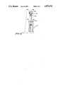
- FIG. 1shows a cross-sectional view of an intramedullary nail according to the present invention.
- FIG. 2shows a sectional view taken along line 2--2 of FIG. 1.
- FIG. 3shows a cross-sectional view taken along line 3--3 of FIG. 1.
- FIG. 4shows a cross-sectional view taken along line 4--4 of FIG. 1.
- FIG. 5shows an alternative cross-sectional configuration taken along line 3--3 of FIG. 1.
- FIG. 6shows an alternative cross-sectional configuration taken along line 4--4 of FIG. 1.
- FIGS. 7-11illustrate the steps of the preferred method of manufacturing the intramedullary nail of the present invention.
- FIG. 12shows a side view of an end cap used for sealing the proximal end of the intramedullary nail of the present invention to prevent tissue ingrowth.
- FIG. 1shows a cross-sectional view of an intramedullary nail 10 constructed in accordance with the principles of the present invention.
- Nail 10has at least three distinct regions or portions which, for purposes of this discussion, will be termed the proximal portion, generally indicated by reference numeral 12, the intermediate portion, generally indicated by reference numeral 14, and the distal portion, generally indicated by reference numeral 16.
- Intramedullary nails of the type illustrated in FIG. 1are typically produced in sizes which range from 8 mm to 20 mm (in 1 mm increments) in diameter, and from 20 cm to 52 cm in length.
- Nail 10 in FIG. 1is typical of a nail in the smaller diameter size range (i.e., 8-13 mm) which is constructed in accordance with the present invention.
- larger nailsmay vary somewhat in overall configuration, specifically with regard to the outer diameter of the proximal portion, or head, of the nail.
- proximal portion 12has a relatively large (as compared to the other portions) outside diameter 18 which is best illustrated in FIG. 2 which is a sectional view taken along line 2--2 of FIG. 1.
- Proximal portion 12also has an inside diameter 20 and a wall thickness 22 which are discussed in more detail below in relation to similar features of the intermediate and distal portions 14 and 16.
- Proximal portion 12is further provided with a slot 24 which extends transversely through proximal portion 12. Slot 24 is provided to allow for passage of a screw or other fixation device, either perpendicularly or at an angle to the longitudinal axis of nail 10, after the nail has been placed in final position within the medullary canal of a fractured bone.
- Proximal portion 12also has internal threads 26 extending from the end of nail 10 into proximal portion 12 for a relatively short distance. Threads 26 receive the threaded portion of an instrument used for inserting and/or extracting the nail from the medullary canal of a bone, as is generally illustrated in, for example, U.S. Pat. Nos. 3,334,624; 4,423,721 and 4,622,959.
- proximal portion 12Also formed in the end of proximal portion 12 are two generally U-shaped grooves 28 and 30 which act as a guide for insertion and extraction tools, or for drill guides used in conjunction with installing fixation screws or fasteners, as is also illustrated in one or more of the above-noted patents.
- Intermediate portion 14has an outside diameter 32, an inside diameter 34, and a wall thickness 36, all of which are best illustrated in FIG. 3 which is a cross-sectional view taken along line 3--3 of FIG. 1.
- outside diameter 32 of intermediate portion 14is smaller than outside diameter 18 of proximal portion 12, while the respective inside diameters 34 and 20 are substantially equal.
- Wall thickness 36 of intermediate portion 14is, accordingly, substantially smaller than wall thickness 22 of proximal portion 12.
- transition region 38Between intermediate portion 14 and proximal portion 12 is a transition region 38 in which the outside diameter tapers from the relatively larger outside diameter 18 of proximal portion 12 to the relatively smaller outside diameter 32 of intermediate portion 14.
- Distal portion 16has an outside diameter 40, an inside diameter 42, and a wall thickness 44 which are best illustrated in FIG. 4 which is a cross-sectional view taken along line 4--4 of FIG. 1.
- Outside diameter 40is substantially equal to outside diameter 32 of intermediate portion 14.
- inside diameter 42 of distal portion 16is substantially smaller than inside diameter 34 of intermediate portion 14, and, accordingly, wall thickness 44 of distal portion 16 is substantially larger than wall thickness 36 of intermediate portion 14.
- distal portion 16is also provided with one or more transverse holes 46 for receiving bone screws or other fixation devices after nail 10 has been placed inside the medullary canal of a fractured bone.
- An end portion 48 of distal portion 16may also be tapered to a point, if desired, in order to assist in insertion of the nail into the medullary canal.
- slot 50which is a longitudinally extending slot which preferably run the entire length of nail 10.
- slot 50allows slot 50 to extend through the entire length of proximal portion 12, while lessening the possibility of proximal portion 12 "spreading" during the insertion and extraction process.
- wall thicknesses 18, 32 and 40are important considerations in the design of the nail of the present invention.
- Typical wall thicknesses for the 13 mm nail illustrated in FIG. 1are 0.118 inch for wall thickness 22 (the proximal portion), 0.059 inch for wall thickness 36 (the intermediate portion), and 0.098 inch for wall thickness 44 (the distal portion). It should be noted that the wall thicknesses 22 and 44 are approximately double that of wall thickness 36.
- nail 10is formed of a single piece of tubing which has no welds or other joints at which weaknesses or defects might occur.
- the relatively thin wall thickness 36 in intermediate portion 14allows nail 10 to retain an appropriate degree of flexibility which allows it to bend in conformance with the shape of the medullary canal into which it is inserted, and provides for a degree of tortional flexibility.
- the relatively thick wall thicknesses 22 and 44 of proximal and distal portions 12 and 16provide extra strength in the areas through which slot 24 and holes 46 extend. These openings produce weaknesses in the nail and very often define the location at which fatigue failure (i.e., breakage) will occur. To maintain this relatively thick wall thickness throughout the length of the nail would result in a decrease in the desired flexibility of the central portion of the nail.
- longitudinal slot 50can be extended all the way through and to the end of Proximal portion 12 with less fear that this portion of the nail will "spread” or open under the pressure of insertion or extraction, or as a result of over-insertion of an instrument used for nail insertion or extraction.
- FIGS. 5 and 6show alternative cross-sectional embodiments taken along lines 3--3 and 4--4 of FIG. 1, respectively. These figures depict a cloverleaf cross-sectional shape which is preferably swaged into intermediate portion 14 and distal portion 16 of nail 10 during the manufacturing process. This shape better defines and concentrates the areas of contact between the outside of the nail and the bone tissue, and is generally preferred over other cross-sectional shapes that may be used.
- FIGS. 7-11illustrate an especially advantageous two-step process which forms an important part of the overall method of manufacturing the nail of the present invention.
- the two steps of this processinclude a machining step and a swaging step, each of which is described in detail below.
- FIG. 7shows a length of tubing 52 which has a relatively uniform outside diameter 54, a relatively uniform inside diameter 56, and a relatively uniform wall thickness 58.
- Tubing 52is a single, unitary section of tubing which has no joints, welds, or other features which might provide a likely location for a weakness or defect.
- Tubing 52is preferably made from stainless steel, although other biocompatible materials such as titanium, titanium alloys, or fiberreinforced non-metallic materials, could be used.
- FIG. 8shows tubing 52 following a machining step in which the wall thickness of intermediate portion 114 has been reduced.
- transition zones 115 and 138are provided in which the outside diameter of tubing 52 tapers between the original diameter and the newly machined outside diameter of intermediate portion 114.
- proximal portion 112 and distal portion 116 of tubing 52may also be machined during this step of the manufacturing process. However, the amount of material removed from the outside diameters of these portions would be less, so that the outer diameter of intermediate portion 114 and, correspondingly, the wall thickness of portion 114 are substantially smaller than the outer diameters and wall thicknesses of proximal and distal portions 112 and 116, respectively, after the machining step is complete.
- the “starting point" for manufacture of the nail as illustrated in FIGS. 7-11is a length of tubing
- the method of the present inventionis not intended to be strictly limited to the use of tubing.
- a length of solid stockcan also be used.
- the machining stepwould include boring (or "gun-drilling") the stock, prior to reducing the outside diameter of the intermediate portion.
- the use of tubingis preferred when stainless steel or other materials readily available in tubing form is used for the nail of the present invention. However, certain materials, such as titanium, may not be as readily available, or may be prohibitatively expensive, in tubing form.
- FIG. 9shows tubing 52 of FIGS. 7 and 8 after a swaging step in which the outside diameter of distal portion 116 has been reduced and made approximately equal to the outside diameter of intermediate portion 114.
- the inside diameter of distal portion 16is reduced during the swaging process, and the wall thickness 58' of portion 116 is maintained, or slightly increased, as compared to the wall thickness of the original tubing.
- the length of distal portion 116may also be increased slightly by the swaging process.
- FIG. 10shows the tubing of FIGS. 7, 8 and 9 after intramedullary nail 110 has been substantially completed.
- Slotted opening 124has been provided through the relatively thick walls of proximal portion 112, and holes 146 have been similarly provided through the relatively thick walls of distal portion 116.
- Internal threads 126have been provided in the end of proximal portion 112.
- An elongated slot 150has also been provided by a machining operation, and extends along the entire length of nail 110.
- Grooves 128 and 130are also provided in the end of proximal portion 112 to mate with and guide appropriate fixtures and instruments Additional finishing steps to complete the nail include polishing, swaging to obtain the cloverleaf cross-section (if desired), and tapering the tip end of distal portion 116.
- FIG. 11shows an intramedullary nail 210 which is at the same stage of completion as nail 110 of FIG. 10.
- Nail 210is typical of a nail in the larger diameter size range (14-20mm) which is constructed in accordance with the present invention.
- Nail 210differs from nail 110 in that the outer diameter of proximal portion 212 is substantially equal to the outside diameters of intermediate and distal portions 214 and 216.
- the inside diameter of proximal portion 212is substantially smaller than the inside diameter of intermediate portion 214. This structure is obtained by swaging proximal portion 212 (or, alternatively, the entire length of nail 210), as well as distal portion 216.
- FIG. 12shows an end part of proximal portion 212 positioned to receive end cap 260.
- End cap 260comprises an elongate threaded portion 262 which is substantially equal in length to internal threads 226 provided in the end of proximal portion 212.
- a seal or washer 264is provided to form a seal between the bottom surface of head 266 of end cap 260 and the end of proximal portion 212. Washer 264 also acts to lock or secure end ca 260 in position after it has been threaded into proximal portion 212.
- Means for attaching or receiving a tool for turning end cap 260are provided in head 266. In the embodiment illustrated in FIG. 12, hexagonally-shaped recess 268 is provided for this purpose.
- end cap 260is used to seal the end of proximal portion 212 and internal threads 226. This prevents the ingrowth of cartilage or other types of tissue into the end of nail 210, and in proximity to threads 226.
- end cap 260is first removed from proximal portion 212 to expose the end of the nail and internal threads 226 in an undamaged condition.
- End cap 260can be formed of the same material used to form the associated nail (e.g., stainless steel, titanium or titanium alloy, etc.) or of any other biologically compatible material. Although like metals are preferred when selecting materials for use with metal nails, plastics (such as UHMWPE) may also be employed in making the end cap.
- material used to form the associated naile.g., stainless steel, titanium or titanium alloy, etc.
- plasticssuch as UHMWPE
- end cap 260is considered to be advantageous with the nails depicted in FIGS. 1-11 of the present application, such advantageous use is not limited to nails which incorporate all the features of these particular designs.
- End cap 260can be used to like advantage in other nails which incorporate internal threads in the proximal end portion, or nails which would otherwise benefit from the provision of a seal in the proximal end of the nail (whether or not threads are provided) to prevent the ingrowth of tissue during the implantation period. Accordingly, the applicability of this aspect of the present invention is to be limited only by the scope of the associated claims.
- the term "swage” or “swaging”is not intended to refer to any one particular metal forming technique, but rather to any of a number of techniques which may be deemed suitable by those of ordinary skill in metal forming to accomplish the results described. Acceptable techniques might also be referred to as “forging” techniques.
- intramedullary nail illustrated and discussed in detail aboveis especially well-suited for treating fractures of the femur, the present invention is not limited to that specific application.
- the principles and features discussedare equally applicable to nails used for treating fractures of the tibia, and for fractures of other long bones commonly treated (or amenable to treatment) by nailing techniques.
Landscapes
- Health & Medical Sciences (AREA)
- Orthopedic Medicine & Surgery (AREA)
- Surgery (AREA)
- Life Sciences & Earth Sciences (AREA)
- Heart & Thoracic Surgery (AREA)
- Nuclear Medicine, Radiotherapy & Molecular Imaging (AREA)
- Engineering & Computer Science (AREA)
- Biomedical Technology (AREA)
- Neurology (AREA)
- Medical Informatics (AREA)
- Molecular Biology (AREA)
- Animal Behavior & Ethology (AREA)
- General Health & Medical Sciences (AREA)
- Public Health (AREA)
- Veterinary Medicine (AREA)
- Surgical Instruments (AREA)
- Prostheses (AREA)
Abstract
Description
This invention relates generally to interlocking intramedullary nails and, more particularly, to a tubular interlocking intramedullary nail having variations in wall thickness along its length.
The use of intramedullary nailing in the treatment of fractures of the femur, tibia, and other "long" bones is well known. This practice can allow a fracture patient to resume limited use of the affected body part within days of the injury and subsequent surgery. The corresponding reduction in the amount of time during which the patient must be at least partially immobilized can drastically reduce the overall recovery period.
One of the earliest forms of intramedullary nails to achieve relative widespread acceptance and usage is often referred to as the Kuntscher nail (or K-nail) for its developer Professor Gerhart Kuntscher of Hamburg, Germany. The Kuntscher nail is a slotted steel tube having a relatively thin side wall thickness which allows the nail to bend or flex slightly as it is driven into the somewhat curved medullary canal of a bone. The Kuntscher nail is also transversely elastic and is approximately the same diameter as the medullary canal into which it is to be driven, causing the nail to be compressed against the sides of the canal and firmly locked in place by compressive forces acting along the length of the nail.
Despite the widespread success and acceptance of the Kuntscher nail, it has been recognized that standard Kuntscher nailing is contraindicated in the treatment of certain complex types of fractures. These fractures are often treated by dynamic or static locking of the nail on one or both ends by screws that extend transversely through the nail and into the major fragments of the fractured bone. This interlocking technique requires the provision of transverse holes or openings through the proximal and/or distal portions of the interlocked nail. Intramedullary nails rarely fail by stress fatigue when no interlocking screws are used. However, the transverse openings and screws of the interlocking nail produce the potential for high concentrations of stress at the proximal and distal ends of the nail, and numerous instances of fatigue failure of interlocking nails have been recorded and analyzed (see, for example "Fatigue Fracture of the Interlocking Nail in the Treatment of Fractures of the Distal Part of the Femoral Shaft" by R. W. Bucholz, M.D., S. E. Ross, M.S. and K. L. Lawrence, Ph.D, P.E., The Journal of Bone and Joint Surgery, Vol. 69-A, No. 9, December, 1987, pp. 1391-1399).
An object of the present invention is to provide an interlocking intramedullary nail which is more resistant to fatigue fractures in the proximal and distal portions of the nail.
Another object of the present invention is to provide an interlocking intramedullary nail which is not only resistant to fatigue fractures, but which retains the desirable flexibility and resilience of the standard Kuntscher nail.
Yet another object of the present invention is to provide an especially advantageous method of manufacturing an interlocking intramedullary nail having the just-described desirable characteristics.
These and other objects of the invention are attained in an intramedullary nail having a proximal portion, a distal portion, and an intermediate portion between the proximal and distal portions, and having at least one opening extending transversely through at least one of either the proximal or distal portions. The nail comprises a unitary piece of elongate material of tubular cross-section having variations in wall thickness along its length. The wall thicknesses of the proximal and distal portions are substantially greater than the wall thickness of the intermediate portion. In an especially preferred embodiment, the wall thicknesses of the proximal and distal portions are approximately twice the thickness of those of the intermediate portion. In one preferred embodiment of the invention, the outside diameters of the distal and intermediate portions are substantially equal, while the outside diameter of the proximal portion is substantially larger. In an alternative embodiment, the outside diameters of the proximal, intermediate and distal portions are substantially equal. In especially preferred embodiments, the nail is provided with a longitudinal slot which extends along substantially the entire length of the nail, and the proximal end of the nail is provided with internal threads to provide for attachment of insertion and extraction devices. The substantially thicker cross-section of the proximal portion of the nail allows such features to be incorporated into the nail design, while maintaining the required strength and mechanical integrity to resist fatigue failure during use and to avoid problems during insertion and extraction.
Another aspect of the present invention relates to the provision of internal threads in the proximal end of the nail for attachment of insertion and extraction devices. It is not uncommon for intramedullary nails of the present type to remain within the body for a number of months, prior to being removed after the fractured bone has healed. During such extended periods, tissue growth around and into the threaded end portion of the nail can occur. Prior to removing the nail, it is necessary for the surgeon to remove such tissue growth to expose the internal threads to allow for attachment of an extraction tool. This is often done by cutting or drilling through the tissue that has grown into the nail, at the risk of damaging surrounding tissue, the nail end, or the internal threads. Accordingly, the nail of the present invention includes a threaded end cap whose function is to seal the end of the nail and the internal threads to prevent tissue ingrowth into these areas.
An especially advantageous method of making an intramedullary nail having variations in wall thickness along its length includes a two-step process to produce the basic overall shape of the nail. The process preferably begins with a single unitary length of tubing having a substantially constant inside diameter, outside diameter and wall thickness. For purposes of this discussion, the length of tubing can be said to have a proximal portion, a distal portion, and an intermediate portion between the proximal and distal portions. The first step in the preferred process is machining the intermediate portion of the length of tubing to reduce the outside diameter and wall thickness thereof, while maintaining the inside diameter substantially constant. The second step in the process is swaging either the proximal portion or the distal portion, or both, to reduce the inside and outside diameter(s) thereof, such that the wall thickness of the swaged portion of the tubing is substantially greater than the wall thickness of the intermediate portion of the tubing. As noted elsewhere in this application, one embodiment of the present invention is swaged such that the outside diameters of the proximal, intermediate, and distal portions are all substantially equal. An alternative embodiment results in a proximal portion which has a slightly larger outside diameter than do the intermediate and distal portions.
Additional machining steps may be performed on the distal and proximal portions of the tubing, either prior to or subsequent to the swaging step. Additional steps may also be performed to provide other features, such as the longitudinally extending slot, transverse openings, and internal threads in the proximal end of the tubing.
Although the preferred sequence of the two-step process is as illustrated in the figures described below, variations from this sequence which would produce substantially the same result are possible. Additionally, although the preferred method of manufacture begins with a single length of tubing, a single length of solid stock (or other material type) may also be used. If a single piece of solid stock is used, the machining step will include drilling at least a portion of the length of stock to produce a tubular cross-section in that portion, followed by the machining and swaging steps described above.
Other objects, advantages and novel features of the present invention will become apparent from the following detailed description of the invention when considered in conjunction with the accompanying drawings.
FIG. 1 shows a cross-sectional view of an intramedullary nail according to the present invention.
FIG. 2 shows a sectional view taken alongline 2--2 of FIG. 1.
FIG. 3 shows a cross-sectional view taken alongline 3--3 of FIG. 1.
FIG. 4 shows a cross-sectional view taken along line 4--4 of FIG. 1.
FIG. 5 shows an alternative cross-sectional configuration taken alongline 3--3 of FIG. 1.
FIG. 6 shows an alternative cross-sectional configuration taken along line 4--4 of FIG. 1.
FIGS. 7-11 illustrate the steps of the preferred method of manufacturing the intramedullary nail of the present invention.
FIG. 12 shows a side view of an end cap used for sealing the proximal end of the intramedullary nail of the present invention to prevent tissue ingrowth.
FIG. 1 shows a cross-sectional view of anintramedullary nail 10 constructed in accordance with the principles of the present invention.Nail 10 has at least three distinct regions or portions which, for purposes of this discussion, will be termed the proximal portion, generally indicated byreference numeral 12, the intermediate portion, generally indicated byreference numeral 14, and the distal portion, generally indicated byreference numeral 16.
Intramedullary nails of the type illustrated in FIG. 1 are typically produced in sizes which range from 8 mm to 20 mm (in 1 mm increments) in diameter, and from 20 cm to 52 cm in length. Nail 10 in FIG. 1 is typical of a nail in the smaller diameter size range (i.e., 8-13 mm) which is constructed in accordance with the present invention. As will be discussed below, larger nails may vary somewhat in overall configuration, specifically with regard to the outer diameter of the proximal portion, or head, of the nail.
Referring to FIG. 1,proximal portion 12 has a relatively large (as compared to the other portions)outside diameter 18 which is best illustrated in FIG. 2 which is a sectional view taken alongline 2--2 of FIG. 1.Proximal portion 12 also has aninside diameter 20 and awall thickness 22 which are discussed in more detail below in relation to similar features of the intermediate anddistal portions
An additional feature ofnail 10 which is partially visible in FIG. 1, and which can be seen in each of FIGS. 2, 3 and 4, isslot 50 which is a longitudinally extending slot which preferably run the entire length ofnail 10. As will be discussed below, the increased wall thickness inproximal portion 12 allowsslot 50 to extend through the entire length ofproximal portion 12, while lessening the possibility ofproximal portion 12 "spreading" during the insertion and extraction process.
The varying dimensions of wall thicknesses 18, 32 and 40 are important considerations in the design of the nail of the present invention. Typical wall thicknesses for the 13 mm nail illustrated in FIG. 1 are 0.118 inch for wall thickness 22 (the proximal portion), 0.059 inch for wall thickness 36 (the intermediate portion), and 0.098 inch for wall thickness 44 (the distal portion). It should be noted that the wall thicknesses 22 and 44 are approximately double that ofwall thickness 36. However,nail 10 is formed of a single piece of tubing which has no welds or other joints at which weaknesses or defects might occur.
The relativelythin wall thickness 36 inintermediate portion 14 allowsnail 10 to retain an appropriate degree of flexibility which allows it to bend in conformance with the shape of the medullary canal into which it is inserted, and provides for a degree of tortional flexibility. The relatively thick wall thicknesses 22 and 44 of proximal anddistal portions slot 24 and holes 46 extend. These openings produce weaknesses in the nail and very often define the location at which fatigue failure (i.e., breakage) will occur. To maintain this relatively thick wall thickness throughout the length of the nail would result in a decrease in the desired flexibility of the central portion of the nail. By forming the nail with substantially greater wall thicknesses in proximal anddistal portions longitudinal slot 50 can be extended all the way through and to the end ofProximal portion 12 with less fear that this portion of the nail will "spread" or open under the pressure of insertion or extraction, or as a result of over-insertion of an instrument used for nail insertion or extraction.
FIGS. 5 and 6 show alternative cross-sectional embodiments taken alonglines 3--3 and 4--4 of FIG. 1, respectively. These figures depict a cloverleaf cross-sectional shape which is preferably swaged intointermediate portion 14 anddistal portion 16 ofnail 10 during the manufacturing process. This shape better defines and concentrates the areas of contact between the outside of the nail and the bone tissue, and is generally preferred over other cross-sectional shapes that may be used.
FIGS. 7-11 illustrate an especially advantageous two-step process which forms an important part of the overall method of manufacturing the nail of the present invention. The two steps of this process include a machining step and a swaging step, each of which is described in detail below.
FIG. 7 shows a length oftubing 52 which has a relatively uniformoutside diameter 54, a relatively uniforminside diameter 56, and a relativelyuniform wall thickness 58.Tubing 52 is a single, unitary section of tubing which has no joints, welds, or other features which might provide a likely location for a weakness or defect.Tubing 52 is preferably made from stainless steel, although other biocompatible materials such as titanium, titanium alloys, or fiberreinforced non-metallic materials, could be used.
FIG. 8 showstubing 52 following a machining step in which the wall thickness ofintermediate portion 114 has been reduced. On either end ofintermediate portion 114,transition zones tubing 52 tapers between the original diameter and the newly machined outside diameter ofintermediate portion 114. If desired,proximal portion 112 anddistal portion 116 oftubing 52 may also be machined during this step of the manufacturing process. However, the amount of material removed from the outside diameters of these portions would be less, so that the outer diameter ofintermediate portion 114 and, correspondingly, the wall thickness ofportion 114 are substantially smaller than the outer diameters and wall thicknesses of proximal anddistal portions
It should be noted at this point that, although the "starting point" for manufacture of the nail as illustrated in FIGS. 7-11 is a length of tubing, the method of the present invention is not intended to be strictly limited to the use of tubing. For example, a length of solid stock can also be used. In that case, the machining step would include boring (or "gun-drilling") the stock, prior to reducing the outside diameter of the intermediate portion. The use of tubing is preferred when stainless steel or other materials readily available in tubing form is used for the nail of the present invention. However, certain materials, such as titanium, may not be as readily available, or may be prohibitatively expensive, in tubing form.
FIG. 9 showstubing 52 of FIGS. 7 and 8 after a swaging step in which the outside diameter ofdistal portion 116 has been reduced and made approximately equal to the outside diameter ofintermediate portion 114. The inside diameter ofdistal portion 16 is reduced during the swaging process, and the wall thickness 58' ofportion 116 is maintained, or slightly increased, as compared to the wall thickness of the original tubing. The length ofdistal portion 116 may also be increased slightly by the swaging process.
FIG. 10 shows the tubing of FIGS. 7, 8 and 9 afterintramedullary nail 110 has been substantially completed. Slottedopening 124 has been provided through the relatively thick walls ofproximal portion 112, and holes 146 have been similarly provided through the relatively thick walls ofdistal portion 116.Internal threads 126 have been provided in the end ofproximal portion 112. Anelongated slot 150 has also been provided by a machining operation, and extends along the entire length ofnail 110.Grooves proximal portion 112 to mate with and guide appropriate fixtures and instruments Additional finishing steps to complete the nail include polishing, swaging to obtain the cloverleaf cross-section (if desired), and tapering the tip end ofdistal portion 116.
It should be noted that the sequence of the machining and swaging operations is not critical (i.e., the swaging operation todistal portion 116 could be performed prior to machining intermediate portion 114). Although the sequence described is the preferred mode of manufacture, and represents the best mode of practicing the invention as presently understood by Applicant, it should be clearly understood that the claims which follow below are not intended to be limited to this preferred sequence.
FIG. 11 shows anintramedullary nail 210 which is at the same stage of completion asnail 110 of FIG. 10.Nail 210 is typical of a nail in the larger diameter size range (14-20mm) which is constructed in accordance with the present invention.Nail 210 differs fromnail 110 in that the outer diameter ofproximal portion 212 is substantially equal to the outside diameters of intermediate anddistal portions proximal portion 212 is substantially smaller than the inside diameter ofintermediate portion 214. This structure is obtained by swaging proximal portion 212 (or, alternatively, the entire length of nail 210), as well asdistal portion 216.
FIG. 12 shows an end part ofproximal portion 212 positioned to receiveend cap 260.End cap 260 comprises an elongate threadedportion 262 which is substantially equal in length tointernal threads 226 provided in the end ofproximal portion 212. A seal orwasher 264 is provided to form a seal between the bottom surface ofhead 266 ofend cap 260 and the end ofproximal portion 212.Washer 264 also acts to lock orsecure end ca 260 in position after it has been threaded intoproximal portion 212. Means for attaching or receiving a tool for turningend cap 260 are provided inhead 266. In the embodiment illustrated in FIG. 12, hexagonally-shapedrecess 268 is provided for this purpose.
Afterintramedullary nail 210 has been positioned within, for example, a fractured femur,end cap 260 is used to seal the end ofproximal portion 212 andinternal threads 226. This prevents the ingrowth of cartilage or other types of tissue into the end ofnail 210, and in proximity tothreads 226. When, at a future date, the nail is to be removed,end cap 260 is first removed fromproximal portion 212 to expose the end of the nail andinternal threads 226 in an undamaged condition.
Although use ofend cap 260 is considered to be advantageous with the nails depicted in FIGS. 1-11 of the present application, such advantageous use is not limited to nails which incorporate all the features of these particular designs.End cap 260 can be used to like advantage in other nails which incorporate internal threads in the proximal end portion, or nails which would otherwise benefit from the provision of a seal in the proximal end of the nail (whether or not threads are provided) to prevent the ingrowth of tissue during the implantation period. Accordingly, the applicability of this aspect of the present invention is to be limited only by the scope of the associated claims.
For purposes of this application, the term "swage" or "swaging" is not intended to refer to any one particular metal forming technique, but rather to any of a number of techniques which may be deemed suitable by those of ordinary skill in metal forming to accomplish the results described. Acceptable techniques might also be referred to as "forging" techniques.
Although the intramedullary nail illustrated and discussed in detail above is especially well-suited for treating fractures of the femur, the present invention is not limited to that specific application. The principles and features discussed are equally applicable to nails used for treating fractures of the tibia, and for fractures of other long bones commonly treated (or amenable to treatment) by nailing techniques.
From the preceding description of the preferred embodiments, it is evident that the objects of the invention are attained. Although the invention has been described and illustrated in detail, it is to be clearly understood that the same is intended by way of illustration and example only and is not to be taken by way of limitation. The spirit and scope of the invention are to be limited only by the terms of the appended claims.
Claims (7)
1. An intramedullary nail, comprising a proximal portion, a distal portion and an intermediate portion between the proximal and distal portions, and having at least one opening extending transversely through at least one of said proximal and distal portions, said nail being formed of a unitary piece of elongate material of tubular cross-section having variations in wall thickness along its length, wherein the wall thicknesses of the proximal and distal portions are substantially greater than the wall thickness of the intermediate portion.
2. An intramedullary nail according to claim 1, wherein the wall thickness of the proximal and distal portions are approximately twice the wall thickness of said intermediate portion.
3. An intramedullary nail according to claim 1, wherein the outside diameters of said distal and intermediate portions are substantially equal along at least a substantial part of said portions.
4. An intramedullary nail according to claim 1, wherein the outside diameters of said proximal, intermediate and distal portions are substantially equal.
5. An intramedullary nail according to claim 1, wherein the nail is provided with a longitudinal slot which extends along substantially the entire length of the nail.
6. An intramedullary nail according to claim 1, wherein a portion of an inside diameter of the proximal portion is threaded to provide a point of attachment for insertion and extraction devices.
7. An intramedullary nail according to claim 6, further comprising an end cap for sealing the threaded portion of the proximal portion after insertion of the nail into a medullary canal of a bone.
Priority Applications (7)
| Application Number | Priority Date | Filing Date | Title |
|---|---|---|---|
| US07/150,025US4875474A (en) | 1988-01-29 | 1988-01-29 | Variable wall thickness interlocking intramedullary nail |
| DE68924965TDE68924965T2 (en) | 1988-01-29 | 1989-01-30 | DETACHABLE INTRAMEDULAR NAIL WITH VARIABLE WALL THICKNESS. |
| JP1502393AJPH03502293A (en) | 1988-01-29 | 1989-01-30 | Variable wall thickness fixation intramedullary nail and its manufacturing method |
| EP89902580AEP0373183B1 (en) | 1988-01-29 | 1989-01-30 | Variable wall thickness interlocking intramedullary nail |
| PCT/US1989/000360WO1989007056A1 (en) | 1988-01-29 | 1989-01-30 | Variable wall thickness interlocking intramedullary nail and method for making same |
| FI903769AFI101448B (en) | 1988-01-29 | 1990-07-27 | A core nail with varying wall thickness |
| DK199001803ADK175818B1 (en) | 1988-01-29 | 1990-07-27 | Interlocking marrow seam with variable wall thickness |
Applications Claiming Priority (1)
| Application Number | Priority Date | Filing Date | Title |
|---|---|---|---|
| US07/150,025US4875474A (en) | 1988-01-29 | 1988-01-29 | Variable wall thickness interlocking intramedullary nail |
Publications (1)
| Publication Number | Publication Date |
|---|---|
| US4875474Atrue US4875474A (en) | 1989-10-24 |
Family
ID=22532798
Family Applications (1)
| Application Number | Title | Priority Date | Filing Date |
|---|---|---|---|
| US07/150,025Expired - LifetimeUS4875474A (en) | 1988-01-29 | 1988-01-29 | Variable wall thickness interlocking intramedullary nail |
Country Status (7)
| Country | Link |
|---|---|
| US (1) | US4875474A (en) |
| EP (1) | EP0373183B1 (en) |
| JP (1) | JPH03502293A (en) |
| DE (1) | DE68924965T2 (en) |
| DK (1) | DK175818B1 (en) |
| FI (1) | FI101448B (en) |
| WO (1) | WO1989007056A1 (en) |
Cited By (86)
| Publication number | Priority date | Publication date | Assignee | Title |
|---|---|---|---|---|
| US5034013A (en)* | 1989-04-24 | 1991-07-23 | Zimmer Inc. | Intramedullary nail |
| US5053035A (en)* | 1990-05-24 | 1991-10-01 | Mclaren Alexander C | Flexible intramedullary fixation rod |
| US5100405A (en)* | 1990-09-07 | 1992-03-31 | Mclaren Alexander C | Locking cap for medical implants |
| US5350379A (en)* | 1993-02-18 | 1994-09-27 | Genesis Orthopedics | Bone and tissue lengthening device |
| US5458600A (en)* | 1991-12-07 | 1995-10-17 | Howmedica Gmbh | Locking nail for hollow bone fractures |
| US5534027A (en)* | 1993-06-21 | 1996-07-09 | Zimmer, Inc. | Method for providing a barrier to the advancement of wear debris in an orthopaedic implant assembly |
| US5536269A (en)* | 1993-02-18 | 1996-07-16 | Genesis Orthopedics | Bone and tissue lengthening device |
| DE19544820A1 (en)* | 1995-10-21 | 1997-04-30 | Pennig Dietmar | Medullary nail for use to extend the femur |
| US5643258A (en)* | 1994-08-10 | 1997-07-01 | Howmedica Gmbh | Device for stabilizing long bones |
| US5643266A (en)* | 1995-06-05 | 1997-07-01 | Li Medical Technologies, Inc. | Method and apparatus for securing ligaments |
| US5645589A (en)* | 1994-08-22 | 1997-07-08 | Li Medical Technologies, Inc. | Anchor and method for securement into a bore |
| US5690649A (en)* | 1995-12-05 | 1997-11-25 | Li Medical Technologies, Inc. | Anchor and anchor installation tool and method |
| US5702215A (en)* | 1995-06-05 | 1997-12-30 | Li Medical Technologies, Inc. | Retractable fixation device |
| US5707395A (en)* | 1997-01-16 | 1998-01-13 | Li Medical Technologies, Inc. | Surgical fastener and method and apparatus for ligament repair |
| US5741300A (en)* | 1996-09-10 | 1998-04-21 | Li Medical Technologies, Inc. | Surgical anchor and package and cartridge for surgical anchor |
| EP0853923A1 (en)* | 1997-01-21 | 1998-07-22 | ORTHOFIX S.r.l. | Intramedullary cavity nail for the treatment of fractures of the hip |
| US5843127A (en)* | 1994-08-22 | 1998-12-01 | Le Medical Technologies, Inc. | Fixation device and method for installing same |
| WO1999034855A1 (en)* | 1998-01-09 | 1999-07-15 | Boston Scientific Limited | Medical device tubing assembly and method of making same |
| US6117161A (en)* | 1995-06-06 | 2000-09-12 | Li Medical Tecnologies, Inc. | Fastener and fastening method, particularly for fastening sutures to bone |
| US6146406A (en)* | 1998-02-12 | 2000-11-14 | Smith & Nephew, Inc. | Bone anchor |
| US6221074B1 (en)* | 1999-06-10 | 2001-04-24 | Orthodyne, Inc. | Femoral intramedullary rod system |
| US6296645B1 (en) | 1999-04-09 | 2001-10-02 | Depuy Orthopaedics, Inc. | Intramedullary nail with non-metal spacers |
| US6547791B1 (en)* | 1998-07-27 | 2003-04-15 | Stryker Trauma - Selzach Ag | Retrograde tibial nail |
| EP1447054A1 (en)* | 2003-02-12 | 2004-08-18 | Centerpulse Orthopedics Ltd. | Device for the removal of implants |
| US6783529B2 (en) | 1999-04-09 | 2004-08-31 | Depuy Orthopaedics, Inc. | Non-metal inserts for bone support assembly |
| US6808527B2 (en) | 2000-04-10 | 2004-10-26 | Depuy Orthopaedics, Inc. | Intramedullary nail with snap-in window insert |
| US20040220668A1 (en)* | 2003-02-12 | 2004-11-04 | Sdgi Holdings, Inc. | Method and device for correcting spondylolisthesis from the lateral approach |
| US20050085917A1 (en)* | 1999-07-02 | 2005-04-21 | Thierry Marnay | Intervertebral implant |
| US20050251261A1 (en)* | 2004-05-05 | 2005-11-10 | Sdgi Holdings, Inc. | Artificial intervertebral disc for lateral insertion |
| US7018380B2 (en) | 1999-06-10 | 2006-03-28 | Cole J Dean | Femoral intramedullary rod system |
| US20060106385A1 (en)* | 2002-09-01 | 2006-05-18 | Dietmar Pennig | Surgical nail and screw fixation system |
| WO2006091460A1 (en)* | 2005-02-18 | 2006-08-31 | Smith & Nephew, Inc. | Hindfoot nail |
| US7207993B1 (en) | 2000-02-03 | 2007-04-24 | Pioneer Laboratories, Inc. | Apparatus and method for repairing the femur |
| US20070156144A1 (en)* | 2004-06-24 | 2007-07-05 | Dieter Ulrich | Intramedullary nail |
| US20070239276A1 (en)* | 2006-04-07 | 2007-10-11 | Sdgi Holdings, Inc. | Artificial disc implants and associated methods and instrumentation |
| WO2007136240A1 (en)* | 2006-05-23 | 2007-11-29 | Sergio Ivan Carrera Chavez | Improvements to locking pins for femur and tibia in the field of trauma medicine |
| US20070288019A1 (en)* | 2004-06-22 | 2007-12-13 | Andre Schlienger | Intramedullary Nail |
| US20080125818A1 (en)* | 2006-09-22 | 2008-05-29 | Sidebotham Christopher G | Interlocking nail geometry and method of use |
| US20080228276A1 (en)* | 2007-03-14 | 2008-09-18 | Warsaw Orthopedic, Inc. | Intervertebral Prosthesis, Instruments, and Methods of Implanting |
| US20080262496A1 (en)* | 2004-06-30 | 2008-10-23 | Sythes (U.S.A.) | Surgical Nail |
| US20090182432A1 (en)* | 1999-06-04 | 2009-07-16 | Warsaw Orthopedic, Inc. | Artificial disc implant |
| US7575600B2 (en) | 2004-09-29 | 2009-08-18 | Kyphon Sarl | Artificial vertebral disk replacement implant with translating articulation contact surface and method |
| US7588577B2 (en) | 2004-07-15 | 2009-09-15 | Wright Medical Technology, Inc. | Guide assembly for intramedullary fixation and method of using the same |
| US7655009B2 (en) | 2003-12-01 | 2010-02-02 | Smith & Nephew, Inc. | Humeral nail |
| US7670377B2 (en) | 2003-11-21 | 2010-03-02 | Kyphon Sarl | Laterally insertable artifical vertebral disk replacement implant with curved spacer |
| US7713271B2 (en) | 2000-09-22 | 2010-05-11 | Piper Medical, Inc. | Intramedullary interlocking fixation devices for the distal radius |
| US20100174284A1 (en)* | 2008-10-15 | 2010-07-08 | Zimmer, Gmbh | Intramedullary nail |
| US20100179551A1 (en)* | 2007-05-25 | 2010-07-15 | Zimmer, Gmbh | Reinforced intramedullary nail |
| US7803162B2 (en) | 2003-07-21 | 2010-09-28 | Spine Solutions, Inc. | Instruments and method for inserting an intervertebral implant |
| US20100312244A1 (en)* | 2009-06-04 | 2010-12-09 | Edwards Scott G | Intramedullary device assembly and associated method |
| US8152807B2 (en) | 2008-03-31 | 2012-04-10 | Olecranail Llc | Intramedullary device assembly and associated method |
| US8287538B2 (en) | 2008-01-14 | 2012-10-16 | Conventus Orthopaedics, Inc. | Apparatus and methods for fracture repair |
| US8337500B2 (en) | 2006-07-31 | 2012-12-25 | Synthes Usa, Llc | Drilling/milling guide and keel cut preparation system |
| US8562606B2 (en) | 2009-12-11 | 2013-10-22 | Small Bone Innovations, Inc. | Ankle fusion device, instrumentation and methods |
| US20130325007A1 (en)* | 2011-02-13 | 2013-12-05 | Carbofix Orthopedics Ltd. | Segmented intramedullary implant |
| US8663224B2 (en) | 2010-09-09 | 2014-03-04 | DePuy Synthes Products, LLC | Surgical nail |
| WO2014078321A1 (en)* | 2012-11-13 | 2014-05-22 | Greenberg Louis E | Orthopedic implant having non-circular cross section and method of use thereof |
| US8771283B2 (en) | 2007-12-17 | 2014-07-08 | Wright Medical Technology, Inc. | Guide assembly for intramedullary fixation and method of using the same |
| US8906022B2 (en) | 2010-03-08 | 2014-12-09 | Conventus Orthopaedics, Inc. | Apparatus and methods for securing a bone implant |
| US8961516B2 (en) | 2005-05-18 | 2015-02-24 | Sonoma Orthopedic Products, Inc. | Straight intramedullary fracture fixation devices and methods |
| US8961518B2 (en) | 2010-01-20 | 2015-02-24 | Conventus Orthopaedics, Inc. | Apparatus and methods for bone access and cavity preparation |
| US8998990B2 (en) | 2006-07-24 | 2015-04-07 | DePuy Synthes Products, LLC | Intervertebral implant with keel |
| US9060820B2 (en) | 2005-05-18 | 2015-06-23 | Sonoma Orthopedic Products, Inc. | Segmented intramedullary fracture fixation devices and methods |
| US9155574B2 (en) | 2006-05-17 | 2015-10-13 | Sonoma Orthopedic Products, Inc. | Bone fixation device, tools and methods |
| US9259250B2 (en) | 2006-11-22 | 2016-02-16 | Sonoma Orthopedic Products, Inc. | Fracture fixation device, tools and methods |
| US9370388B2 (en) | 2010-06-07 | 2016-06-21 | Carbofix Orthopedics Ltd. | Composite material bone implant |
| US9451971B2 (en) | 2004-07-15 | 2016-09-27 | Agilent Technologies, Inc. | Intramedullary fixation assembly and devices and methods for installing the same |
| US9526549B2 (en) | 2012-01-16 | 2016-12-27 | Carbofix Orthopedics Ltd. | Bone screw with insert |
| US9730739B2 (en) | 2010-01-15 | 2017-08-15 | Conventus Orthopaedics, Inc. | Rotary-rigid orthopaedic rod |
| US9770278B2 (en) | 2014-01-17 | 2017-09-26 | Arthrex, Inc. | Dual tip guide wire |
| US9814499B2 (en) | 2014-09-30 | 2017-11-14 | Arthrex, Inc. | Intramedullary fracture fixation devices and methods |
| US10022132B2 (en) | 2013-12-12 | 2018-07-17 | Conventus Orthopaedics, Inc. | Tissue displacement tools and methods |
| US10028777B2 (en) | 2009-01-16 | 2018-07-24 | Carbofix Orthopedics Ltd. | Composite material bone implant |
| US10154867B2 (en) | 2010-06-07 | 2018-12-18 | Carbofix In Orthopedics Llc | Multi-layer composite material bone screw |
| US10182831B2 (en) | 2003-04-28 | 2019-01-22 | Centinel Spine Llc | Instruments and method for preparing an intervertebral space for receiving an artificial disc implant |
| US20190117282A1 (en)* | 2015-12-28 | 2019-04-25 | Glenhurst Labs, Llc | Surgical devices for small bone fracture surgery |
| US10610270B2 (en) | 2018-01-15 | 2020-04-07 | Glw, Inc. | Hybrid intramedullary rods |
| US10617458B2 (en) | 2015-12-23 | 2020-04-14 | Carbofix In Orthopedics Llc | Multi-layer composite material bone screw |
| US10918426B2 (en) | 2017-07-04 | 2021-02-16 | Conventus Orthopaedics, Inc. | Apparatus and methods for treatment of a bone |
| WO2021081168A1 (en)* | 2019-10-25 | 2021-04-29 | Skeletal Dynamics, Inc | Intramedullary fixation nail and method of use |
| CN113274112A (en)* | 2021-05-21 | 2021-08-20 | 南昌大学第一附属医院 | Production method of magnesium alloy hollow lag screw |
| US20220151664A1 (en)* | 2015-04-16 | 2022-05-19 | Texas Tech University System | Ankle (Tibio-Talar) Fusion Nail |
| US11426220B2 (en) | 2017-10-11 | 2022-08-30 | Howmedica Osteonics Corp. | Humeral fixation plate guides |
| US11596419B2 (en) | 2017-03-09 | 2023-03-07 | Flower Orthopedics Corporation | Plating depth gauge and countersink instrument |
| US11890202B2 (en) | 2007-06-20 | 2024-02-06 | 3Spine, Inc. | Spinal osteotomy |
| US12409046B2 (en) | 2022-04-12 | 2025-09-09 | 3Spine, Inc. | Total spinal joint systems with motion moderators |
Families Citing this family (7)
| Publication number | Priority date | Publication date | Assignee | Title |
|---|---|---|---|---|
| DE9109883U1 (en)* | 1991-08-09 | 1991-09-26 | Howmedica GmbH, 2314 Schönkirchen | Locking nail for the treatment of femoral fractures in the middle and trochanteric region |
| DE9205099U1 (en)* | 1992-04-11 | 1992-06-17 | Howmedica GmbH, 2314 Schönkirchen | Humeral nail |
| DE29818323U1 (en)* | 1998-10-02 | 1999-01-28 | Aap Implantate Ag | Intramedullary nail |
| EP2060237B1 (en) | 2007-11-13 | 2011-10-19 | CITIEFFE S.r.l. | Removable closure unit for axial bone consolidation implants |
| BRPI0920250A2 (en) | 2008-10-15 | 2016-11-22 | Smith & Nephew Inc | composite internal fasteners |
| CN103648440B (en)* | 2011-07-15 | 2017-08-08 | 史密夫和内修有限公司 | Reduced implant stress zones |
| JP2015129449A (en)* | 2014-01-07 | 2015-07-16 | 愛三工業株式会社 | Abnormality determination device |
Citations (23)
| Publication number | Priority date | Publication date | Assignee | Title |
|---|---|---|---|---|
| US2136471A (en)* | 1937-06-30 | 1938-11-15 | Rudolph H Schneider | Bone pin |
| US2518019A (en)* | 1946-11-29 | 1950-08-08 | Kane John Timothy | Intramedullary splint |
| US3334624A (en)* | 1963-09-26 | 1967-08-08 | Synthes Ag | Intramedullary nail |
| US3433220A (en)* | 1966-12-30 | 1969-03-18 | Robert E Zickel | Intramedullary rod and cross-nail assembly for treating femur fractures |
| US3977398A (en)* | 1976-01-12 | 1976-08-31 | The Sampson Corporation | Fluted sub-trochanteric nail system |
| US3990438A (en)* | 1975-04-21 | 1976-11-09 | Pritchard Rowland W | Bone fracture fixation and compression apparatus |
| US4103683A (en)* | 1977-06-03 | 1978-08-01 | Neufeld John A | Sub-trochanteric nail |
| US4212683A (en)* | 1978-03-27 | 1980-07-15 | Ncr Corporation | Method for making narrow channel FET |
| GB1593440A (en)* | 1977-04-23 | 1981-07-15 | Howmedica | Intramedullary nails |
| SU902736A1 (en)* | 1980-03-05 | 1982-02-07 | Воронежский государственный медицинский институт им.Н.Н.Бурденко | Intrabone fixative |
| US4341206A (en)* | 1978-12-19 | 1982-07-27 | Synthes Ag | Device for producing a hole in a bone |
| US4375810A (en)* | 1979-01-04 | 1983-03-08 | Belykh Sergei I | Joining element for fixation of bone tissues |
| US4381770A (en)* | 1981-10-26 | 1983-05-03 | Neufeld Alonzo J | Method and apparatus for performing percutaneous bone surgery and new pin implant |
| GB2114005A (en)* | 1982-01-15 | 1983-08-17 | Krupp Gmbh | Marrow nail |
| US4423721A (en)* | 1978-09-04 | 1984-01-03 | Schwarzkopf Development Corporation | Device for insertion and extraction of medullary nails |
| US4446857A (en)* | 1978-09-04 | 1984-05-08 | Schwarzkopf Development Corporation | Medullary nail and process for the production thereof |
| SU1091921A1 (en)* | 1982-11-12 | 1984-05-15 | Koptyukh Vladimir V | Intraosseous fixative for the treatment of fractures of long tubular bones |
| US4457301A (en)* | 1982-06-18 | 1984-07-03 | Howmedica Inc. | Intramedullary fixation device |
| US4475545A (en)* | 1982-12-06 | 1984-10-09 | Ender Hans G | Bone-nail |
| US4622959A (en)* | 1985-03-05 | 1986-11-18 | Marcus Randall E | Multi-use femoral intramedullary nail |
| US4628920A (en)* | 1983-12-12 | 1986-12-16 | Synthes Ltd. | Intramedullary nail |
| US4697585A (en)* | 1985-01-11 | 1987-10-06 | Williams Michael O | Appliance for fixing fractures of the femur |
| US4776330A (en)* | 1986-06-23 | 1988-10-11 | Pfizer Hospital Products Group, Inc. | Modular femoral fixation system |
Family Cites Families (9)
| Publication number | Priority date | Publication date | Assignee | Title |
|---|---|---|---|---|
| FR791652A (en)* | 1935-06-24 | 1935-12-14 | Bottom bracket hollow and internally profiled, for bicycles, motorcycles, etc. | |
| US2125106A (en)* | 1935-09-30 | 1938-07-26 | Aviat Mfg Corp | Method of producing cylinders for internal combustion engines |
| US2494128A (en)* | 1945-11-14 | 1950-01-10 | Nat Supply Co | Method of increasing the axial tensile strength of threaded joints |
| DE928929C (en)* | 1948-10-02 | 1955-06-13 | Eisen & Stahlind Ag | Process for the production of tubular hollow bodies, in particular hollow piston slide rods for steam locomotives |
| AT256007B (en)* | 1963-11-21 | 1967-08-10 | Kieserling & Albrecht | Device for attaching folding rods to pipe ends, in particular to thin-walled pipes |
| US3892117A (en)* | 1973-03-28 | 1975-07-01 | Milton E Nelson | Method of manufacturing lightweight dental drill for high-speed dental handpiece |
| US3842632A (en)* | 1973-03-28 | 1974-10-22 | M Nelson | Method of manufacture of lightweight,high-speed dental drill |
| JPS5845130Y2 (en)* | 1979-09-07 | 1983-10-14 | 日本発条株式会社 | Hollow stabilizer for vehicles |
| US4435972A (en)* | 1982-06-28 | 1984-03-13 | Simon Joseph A | Process for forming integral spindle-axle tubes |
- 1988
- 1988-01-29USUS07/150,025patent/US4875474A/ennot_activeExpired - Lifetime
- 1989
- 1989-01-30WOPCT/US1989/000360patent/WO1989007056A1/enactiveIP Right Grant
- 1989-01-30EPEP89902580Apatent/EP0373183B1/ennot_activeExpired - Lifetime
- 1989-01-30DEDE68924965Tpatent/DE68924965T2/ennot_activeExpired - Fee Related
- 1989-01-30JPJP1502393Apatent/JPH03502293A/enactivePending
- 1990
- 1990-07-27FIFI903769Apatent/FI101448B/ennot_activeIP Right Cessation
- 1990-07-27DKDK199001803Apatent/DK175818B1/ennot_activeIP Right Cessation
Patent Citations (23)
| Publication number | Priority date | Publication date | Assignee | Title |
|---|---|---|---|---|
| US2136471A (en)* | 1937-06-30 | 1938-11-15 | Rudolph H Schneider | Bone pin |
| US2518019A (en)* | 1946-11-29 | 1950-08-08 | Kane John Timothy | Intramedullary splint |
| US3334624A (en)* | 1963-09-26 | 1967-08-08 | Synthes Ag | Intramedullary nail |
| US3433220A (en)* | 1966-12-30 | 1969-03-18 | Robert E Zickel | Intramedullary rod and cross-nail assembly for treating femur fractures |
| US3990438A (en)* | 1975-04-21 | 1976-11-09 | Pritchard Rowland W | Bone fracture fixation and compression apparatus |
| US3977398A (en)* | 1976-01-12 | 1976-08-31 | The Sampson Corporation | Fluted sub-trochanteric nail system |
| GB1593440A (en)* | 1977-04-23 | 1981-07-15 | Howmedica | Intramedullary nails |
| US4103683A (en)* | 1977-06-03 | 1978-08-01 | Neufeld John A | Sub-trochanteric nail |
| US4212683A (en)* | 1978-03-27 | 1980-07-15 | Ncr Corporation | Method for making narrow channel FET |
| US4446857A (en)* | 1978-09-04 | 1984-05-08 | Schwarzkopf Development Corporation | Medullary nail and process for the production thereof |
| US4423721A (en)* | 1978-09-04 | 1984-01-03 | Schwarzkopf Development Corporation | Device for insertion and extraction of medullary nails |
| US4341206A (en)* | 1978-12-19 | 1982-07-27 | Synthes Ag | Device for producing a hole in a bone |
| US4375810A (en)* | 1979-01-04 | 1983-03-08 | Belykh Sergei I | Joining element for fixation of bone tissues |
| SU902736A1 (en)* | 1980-03-05 | 1982-02-07 | Воронежский государственный медицинский институт им.Н.Н.Бурденко | Intrabone fixative |
| US4381770A (en)* | 1981-10-26 | 1983-05-03 | Neufeld Alonzo J | Method and apparatus for performing percutaneous bone surgery and new pin implant |
| GB2114005A (en)* | 1982-01-15 | 1983-08-17 | Krupp Gmbh | Marrow nail |
| US4457301A (en)* | 1982-06-18 | 1984-07-03 | Howmedica Inc. | Intramedullary fixation device |
| SU1091921A1 (en)* | 1982-11-12 | 1984-05-15 | Koptyukh Vladimir V | Intraosseous fixative for the treatment of fractures of long tubular bones |
| US4475545A (en)* | 1982-12-06 | 1984-10-09 | Ender Hans G | Bone-nail |
| US4628920A (en)* | 1983-12-12 | 1986-12-16 | Synthes Ltd. | Intramedullary nail |
| US4697585A (en)* | 1985-01-11 | 1987-10-06 | Williams Michael O | Appliance for fixing fractures of the femur |
| US4622959A (en)* | 1985-03-05 | 1986-11-18 | Marcus Randall E | Multi-use femoral intramedullary nail |
| US4776330A (en)* | 1986-06-23 | 1988-10-11 | Pfizer Hospital Products Group, Inc. | Modular femoral fixation system |
Cited By (147)
| Publication number | Priority date | Publication date | Assignee | Title |
|---|---|---|---|---|
| US5034013A (en)* | 1989-04-24 | 1991-07-23 | Zimmer Inc. | Intramedullary nail |
| US5053035A (en)* | 1990-05-24 | 1991-10-01 | Mclaren Alexander C | Flexible intramedullary fixation rod |
| US5100405A (en)* | 1990-09-07 | 1992-03-31 | Mclaren Alexander C | Locking cap for medical implants |
| US5458600A (en)* | 1991-12-07 | 1995-10-17 | Howmedica Gmbh | Locking nail for hollow bone fractures |
| US5350379A (en)* | 1993-02-18 | 1994-09-27 | Genesis Orthopedics | Bone and tissue lengthening device |
| US5536269A (en)* | 1993-02-18 | 1996-07-16 | Genesis Orthopedics | Bone and tissue lengthening device |
| US5534032A (en)* | 1993-06-21 | 1996-07-09 | Zimmer, Inc. | Orthopaedic implant assembly |
| US5534027A (en)* | 1993-06-21 | 1996-07-09 | Zimmer, Inc. | Method for providing a barrier to the advancement of wear debris in an orthopaedic implant assembly |
| US5643258A (en)* | 1994-08-10 | 1997-07-01 | Howmedica Gmbh | Device for stabilizing long bones |
| US5645589A (en)* | 1994-08-22 | 1997-07-08 | Li Medical Technologies, Inc. | Anchor and method for securement into a bore |
| US5843127A (en)* | 1994-08-22 | 1998-12-01 | Le Medical Technologies, Inc. | Fixation device and method for installing same |
| US5643266A (en)* | 1995-06-05 | 1997-07-01 | Li Medical Technologies, Inc. | Method and apparatus for securing ligaments |
| US5702215A (en)* | 1995-06-05 | 1997-12-30 | Li Medical Technologies, Inc. | Retractable fixation device |
| US6117161A (en)* | 1995-06-06 | 2000-09-12 | Li Medical Tecnologies, Inc. | Fastener and fastening method, particularly for fastening sutures to bone |
| DE19544820A1 (en)* | 1995-10-21 | 1997-04-30 | Pennig Dietmar | Medullary nail for use to extend the femur |
| US5690649A (en)* | 1995-12-05 | 1997-11-25 | Li Medical Technologies, Inc. | Anchor and anchor installation tool and method |
| US5741300A (en)* | 1996-09-10 | 1998-04-21 | Li Medical Technologies, Inc. | Surgical anchor and package and cartridge for surgical anchor |
| US5707395A (en)* | 1997-01-16 | 1998-01-13 | Li Medical Technologies, Inc. | Surgical fastener and method and apparatus for ligament repair |
| US6126661A (en)* | 1997-01-20 | 2000-10-03 | Orthofix S.R.L. | Intramedullary cavity nail and kit for the treatment of fractures of the hip |
| EP0853923A1 (en)* | 1997-01-21 | 1998-07-22 | ORTHOFIX S.r.l. | Intramedullary cavity nail for the treatment of fractures of the hip |
| WO1999034855A1 (en)* | 1998-01-09 | 1999-07-15 | Boston Scientific Limited | Medical device tubing assembly and method of making same |
| US6146406A (en)* | 1998-02-12 | 2000-11-14 | Smith & Nephew, Inc. | Bone anchor |
| US6547791B1 (en)* | 1998-07-27 | 2003-04-15 | Stryker Trauma - Selzach Ag | Retrograde tibial nail |
| US6783529B2 (en) | 1999-04-09 | 2004-08-31 | Depuy Orthopaedics, Inc. | Non-metal inserts for bone support assembly |
| US6296645B1 (en) | 1999-04-09 | 2001-10-02 | Depuy Orthopaedics, Inc. | Intramedullary nail with non-metal spacers |
| US6709436B1 (en) | 1999-04-09 | 2004-03-23 | Depuy Orthopaedics, Inc. | Non-metal spacers for intramedullary nail |
| US6786908B2 (en) | 1999-04-09 | 2004-09-07 | Depuy Orthopaedics, Inc. | Bone fracture support implant with non-metal spacers |
| US20090182432A1 (en)* | 1999-06-04 | 2009-07-16 | Warsaw Orthopedic, Inc. | Artificial disc implant |
| US6402753B1 (en) | 1999-06-10 | 2002-06-11 | Orthodyne, Inc. | Femoral intramedullary rod system |
| US7867231B2 (en) | 1999-06-10 | 2011-01-11 | Cole J Dean | Femoral intramedullary rod system |
| US7018380B2 (en) | 1999-06-10 | 2006-03-28 | Cole J Dean | Femoral intramedullary rod system |
| US7041104B1 (en) | 1999-06-10 | 2006-05-09 | Orthodyne, Inc. | Femoral intramedullary rod system |
| US6221074B1 (en)* | 1999-06-10 | 2001-04-24 | Orthodyne, Inc. | Femoral intramedullary rod system |
| US20060122600A1 (en)* | 1999-06-10 | 2006-06-08 | Orthodyne, Inc. | Femoral intramedullary rod system |
| US9526624B2 (en) | 1999-07-02 | 2016-12-27 | DePuy Synthes Products, Inc. | Intervertebral implant |
| US8506634B2 (en) | 1999-07-02 | 2013-08-13 | DePuy Synthes Products, LLC | Intervertebral implant |
| US8795371B2 (en) | 1999-07-02 | 2014-08-05 | DePuy Synthes Products, LLC | Intervertebral implant |
| US8882839B2 (en) | 1999-07-02 | 2014-11-11 | DePuy Synthes Products, LLC | Intervertebral implant |
| US20050085917A1 (en)* | 1999-07-02 | 2005-04-21 | Thierry Marnay | Intervertebral implant |
| US8974530B2 (en) | 1999-07-02 | 2015-03-10 | DePuy Synthes Products, LLC | Intervertebral implant |
| US20070265707A1 (en)* | 1999-07-02 | 2007-11-15 | Thierry Marnay | Intervertebral implant |
| US7207993B1 (en) | 2000-02-03 | 2007-04-24 | Pioneer Laboratories, Inc. | Apparatus and method for repairing the femur |
| US6808527B2 (en) | 2000-04-10 | 2004-10-26 | Depuy Orthopaedics, Inc. | Intramedullary nail with snap-in window insert |
| US7713271B2 (en) | 2000-09-22 | 2010-05-11 | Piper Medical, Inc. | Intramedullary interlocking fixation devices for the distal radius |
| US8100910B2 (en) | 2000-09-22 | 2012-01-24 | Piper Medical, Inc. | Intramedullary interlocking fixation devices for the distal radius |
| US8092453B2 (en) | 2000-09-22 | 2012-01-10 | Piper Medical, Inc. | Intramedullary interlocking fixation devices for the distal radius |
| US20060106385A1 (en)* | 2002-09-01 | 2006-05-18 | Dietmar Pennig | Surgical nail and screw fixation system |
| EP1447054A1 (en)* | 2003-02-12 | 2004-08-18 | Centerpulse Orthopedics Ltd. | Device for the removal of implants |
| US20040193176A1 (en)* | 2003-02-12 | 2004-09-30 | Heinz Gerngross | Implant removal |
| US20040220668A1 (en)* | 2003-02-12 | 2004-11-04 | Sdgi Holdings, Inc. | Method and device for correcting spondylolisthesis from the lateral approach |
| US20040220670A1 (en)* | 2003-02-12 | 2004-11-04 | Sdgi Holdings, Inc. | Articular disc prosthesis and method for treating spondylolisthesis |
| US20100324684A1 (en)* | 2003-02-12 | 2010-12-23 | Warsaw Orthopedic, Inc. | Spinal Prosthetic Joints |
| US7850735B2 (en) | 2003-02-12 | 2010-12-14 | Warsaw Orthopedic, Inc. | Articular disc prosthesis and method for treating spondylolisthesis |
| US10182831B2 (en) | 2003-04-28 | 2019-01-22 | Centinel Spine Llc | Instruments and method for preparing an intervertebral space for receiving an artificial disc implant |
| US7803162B2 (en) | 2003-07-21 | 2010-09-28 | Spine Solutions, Inc. | Instruments and method for inserting an intervertebral implant |
| US8349017B2 (en) | 2003-07-21 | 2013-01-08 | Spine Solutions, Inc. | Instruments and method for inserting an intervertebral implant |
| US7670377B2 (en) | 2003-11-21 | 2010-03-02 | Kyphon Sarl | Laterally insertable artifical vertebral disk replacement implant with curved spacer |
| US7691146B2 (en) | 2003-11-21 | 2010-04-06 | Kyphon Sarl | Method of laterally inserting an artificial vertebral disk replacement implant with curved spacer |
| US7655009B2 (en) | 2003-12-01 | 2010-02-02 | Smith & Nephew, Inc. | Humeral nail |
| US20050251261A1 (en)* | 2004-05-05 | 2005-11-10 | Sdgi Holdings, Inc. | Artificial intervertebral disc for lateral insertion |
| US7892234B2 (en) | 2004-06-22 | 2011-02-22 | Synthes Usa, Llc | Intramedullary nail |
| US20070288019A1 (en)* | 2004-06-22 | 2007-12-13 | Andre Schlienger | Intramedullary Nail |
| US20070156144A1 (en)* | 2004-06-24 | 2007-07-05 | Dieter Ulrich | Intramedullary nail |
| US20080262496A1 (en)* | 2004-06-30 | 2008-10-23 | Sythes (U.S.A.) | Surgical Nail |
| US8066706B2 (en) | 2004-06-30 | 2011-11-29 | Synthes Usa, Llc | Surgical nail |
| US9451971B2 (en) | 2004-07-15 | 2016-09-27 | Agilent Technologies, Inc. | Intramedullary fixation assembly and devices and methods for installing the same |
| US8034056B2 (en) | 2004-07-15 | 2011-10-11 | Wright Medical Technology, Inc. | Guide assembly for intramedullary fixation and method of using the same |
| US7588577B2 (en) | 2004-07-15 | 2009-09-15 | Wright Medical Technology, Inc. | Guide assembly for intramedullary fixation and method of using the same |
| US7575600B2 (en) | 2004-09-29 | 2009-08-18 | Kyphon Sarl | Artificial vertebral disk replacement implant with translating articulation contact surface and method |
| US7410488B2 (en) | 2005-02-18 | 2008-08-12 | Smith & Nephew, Inc. | Hindfoot nail |
| WO2006091460A1 (en)* | 2005-02-18 | 2006-08-31 | Smith & Nephew, Inc. | Hindfoot nail |
| USRE46008E1 (en) | 2005-02-18 | 2016-05-24 | Smith & Nephew, Inc. | Hindfoot nail |
| USRE46078E1 (en) | 2005-02-18 | 2016-07-26 | Smith & Nephew, Inc. | Hindfoot nail |
| USRE44501E1 (en) | 2005-02-18 | 2013-09-17 | Smith & Nephew, Inc. | Hindfoot nail |
| US9060820B2 (en) | 2005-05-18 | 2015-06-23 | Sonoma Orthopedic Products, Inc. | Segmented intramedullary fracture fixation devices and methods |
| US8961516B2 (en) | 2005-05-18 | 2015-02-24 | Sonoma Orthopedic Products, Inc. | Straight intramedullary fracture fixation devices and methods |
| US8066774B2 (en) | 2006-04-07 | 2011-11-29 | Warsaw Orthopedic, Inc. | Artificial disc implants and associated methods and instrumentation |
| US20070239276A1 (en)* | 2006-04-07 | 2007-10-11 | Sdgi Holdings, Inc. | Artificial disc implants and associated methods and instrumentation |
| US9155574B2 (en) | 2006-05-17 | 2015-10-13 | Sonoma Orthopedic Products, Inc. | Bone fixation device, tools and methods |
| WO2007136240A1 (en)* | 2006-05-23 | 2007-11-29 | Sergio Ivan Carrera Chavez | Improvements to locking pins for femur and tibia in the field of trauma medicine |
| US10583014B2 (en) | 2006-07-24 | 2020-03-10 | Centinel Spine, Llc | Intervertebral implant with keel |
| US11690728B2 (en) | 2006-07-24 | 2023-07-04 | Centinel Spine, Llc | Intervertebral implant with keel |
| US8998990B2 (en) | 2006-07-24 | 2015-04-07 | DePuy Synthes Products, LLC | Intervertebral implant with keel |
| US9387086B2 (en) | 2006-07-24 | 2016-07-12 | DePuy Synthes Products, Inc. | Intervertebral implant with keel |
| US9883950B2 (en) | 2006-07-24 | 2018-02-06 | Centinel Spine Llc | Intervertebral implant with keel |
| US8337500B2 (en) | 2006-07-31 | 2012-12-25 | Synthes Usa, Llc | Drilling/milling guide and keel cut preparation system |
| US9949746B2 (en) | 2006-07-31 | 2018-04-24 | Centinel Spine Llc | Drilling/milling guide and keel cut preparation system |
| US9717511B2 (en) | 2006-07-31 | 2017-08-01 | DePuy Synthes Products, Inc. | Drilling/milling guide and keel cut preparation system |
| US9254139B2 (en) | 2006-07-31 | 2016-02-09 | DePuy Synthes Products, Inc. | Drilling/milling guide and keel cut preparation system |
| US8758345B2 (en)* | 2006-09-22 | 2014-06-24 | Christopher G. Sidebotham | Interlocking nail geometry and method of use |
| US20080125818A1 (en)* | 2006-09-22 | 2008-05-29 | Sidebotham Christopher G | Interlocking nail geometry and method of use |
| US9259250B2 (en) | 2006-11-22 | 2016-02-16 | Sonoma Orthopedic Products, Inc. | Fracture fixation device, tools and methods |
| US20080228276A1 (en)* | 2007-03-14 | 2008-09-18 | Warsaw Orthopedic, Inc. | Intervertebral Prosthesis, Instruments, and Methods of Implanting |
| US9597129B2 (en) | 2007-05-25 | 2017-03-21 | Zimmer Gmbh | Reinforced intramedullary nail |
| US20100179551A1 (en)* | 2007-05-25 | 2010-07-15 | Zimmer, Gmbh | Reinforced intramedullary nail |
| US11890202B2 (en) | 2007-06-20 | 2024-02-06 | 3Spine, Inc. | Spinal osteotomy |
| US9662153B2 (en) | 2007-12-17 | 2017-05-30 | Wright Medical Technology, Inc. | Guide assembly for intramedullary fixation and method of using the same |
| US8771283B2 (en) | 2007-12-17 | 2014-07-08 | Wright Medical Technology, Inc. | Guide assembly for intramedullary fixation and method of using the same |
| US9517093B2 (en) | 2008-01-14 | 2016-12-13 | Conventus Orthopaedics, Inc. | Apparatus and methods for fracture repair |
| US9788870B2 (en) | 2008-01-14 | 2017-10-17 | Conventus Orthopaedics, Inc. | Apparatus and methods for fracture repair |
| US10603087B2 (en) | 2008-01-14 | 2020-03-31 | Conventus Orthopaedics, Inc. | Apparatus and methods for fracture repair |
| US11399878B2 (en) | 2008-01-14 | 2022-08-02 | Conventus Orthopaedics, Inc. | Apparatus and methods for fracture repair |
| US8287538B2 (en) | 2008-01-14 | 2012-10-16 | Conventus Orthopaedics, Inc. | Apparatus and methods for fracture repair |
| US8152807B2 (en) | 2008-03-31 | 2012-04-10 | Olecranail Llc | Intramedullary device assembly and associated method |
| US20100174284A1 (en)* | 2008-10-15 | 2010-07-08 | Zimmer, Gmbh | Intramedullary nail |
| US8668695B2 (en) | 2008-10-15 | 2014-03-11 | Zimmer Gmbh | Intramedullary nail |
| US9474557B2 (en) | 2008-10-15 | 2016-10-25 | Zimmer Gmbh | Intramedullary nail |
| US10028777B2 (en) | 2009-01-16 | 2018-07-24 | Carbofix Orthopedics Ltd. | Composite material bone implant |
| US20100312244A1 (en)* | 2009-06-04 | 2010-12-09 | Edwards Scott G | Intramedullary device assembly and associated method |
| US8216237B2 (en) | 2009-06-04 | 2012-07-10 | Edwards Scott G | Intramedullary device assembly and associated method |
| US8562606B2 (en) | 2009-12-11 | 2013-10-22 | Small Bone Innovations, Inc. | Ankle fusion device, instrumentation and methods |
| US9308037B2 (en) | 2009-12-11 | 2016-04-12 | Stryker European Holdings I, Llc | Ankle fusion device, instrumentation and methods |
| US9730739B2 (en) | 2010-01-15 | 2017-08-15 | Conventus Orthopaedics, Inc. | Rotary-rigid orthopaedic rod |
| US9848889B2 (en) | 2010-01-20 | 2017-12-26 | Conventus Orthopaedics, Inc. | Apparatus and methods for bone access and cavity preparation |
| US8961518B2 (en) | 2010-01-20 | 2015-02-24 | Conventus Orthopaedics, Inc. | Apparatus and methods for bone access and cavity preparation |
| US9993277B2 (en) | 2010-03-08 | 2018-06-12 | Conventus Orthopaedics, Inc. | Apparatus and methods for securing a bone implant |
| US8906022B2 (en) | 2010-03-08 | 2014-12-09 | Conventus Orthopaedics, Inc. | Apparatus and methods for securing a bone implant |
| US10849668B2 (en) | 2010-06-07 | 2020-12-01 | Carbofix Orthopedics Ltd. | Composite material bone implant |
| US10154867B2 (en) | 2010-06-07 | 2018-12-18 | Carbofix In Orthopedics Llc | Multi-layer composite material bone screw |
| US9974586B2 (en) | 2010-06-07 | 2018-05-22 | Carbofix Orthopedics Ltd. | Composite material bone implant |
| US9370388B2 (en) | 2010-06-07 | 2016-06-21 | Carbofix Orthopedics Ltd. | Composite material bone implant |
| US8663224B2 (en) | 2010-09-09 | 2014-03-04 | DePuy Synthes Products, LLC | Surgical nail |
| US20130325007A1 (en)* | 2011-02-13 | 2013-12-05 | Carbofix Orthopedics Ltd. | Segmented intramedullary implant |
| US9526549B2 (en) | 2012-01-16 | 2016-12-27 | Carbofix Orthopedics Ltd. | Bone screw with insert |
| WO2014078321A1 (en)* | 2012-11-13 | 2014-05-22 | Greenberg Louis E | Orthopedic implant having non-circular cross section and method of use thereof |
| US9775648B2 (en) | 2012-11-13 | 2017-10-03 | Louis E. Greenberg | Orthopedic implant having non-circular cross section and method of use thereof |
| US10022132B2 (en) | 2013-12-12 | 2018-07-17 | Conventus Orthopaedics, Inc. | Tissue displacement tools and methods |
| US10076342B2 (en) | 2013-12-12 | 2018-09-18 | Conventus Orthopaedics, Inc. | Tissue displacement tools and methods |
| US9770278B2 (en) | 2014-01-17 | 2017-09-26 | Arthrex, Inc. | Dual tip guide wire |
| US10548648B2 (en) | 2014-09-30 | 2020-02-04 | Arthrex, Inc. | Intramedullary fracture fixation devices and methods |
| US9814499B2 (en) | 2014-09-30 | 2017-11-14 | Arthrex, Inc. | Intramedullary fracture fixation devices and methods |
| US20220151664A1 (en)* | 2015-04-16 | 2022-05-19 | Texas Tech University System | Ankle (Tibio-Talar) Fusion Nail |
| US10617458B2 (en) | 2015-12-23 | 2020-04-14 | Carbofix In Orthopedics Llc | Multi-layer composite material bone screw |
| US10898242B2 (en)* | 2015-12-28 | 2021-01-26 | Glenhurst Labs, Llc | Surgical devices for small bone fracture surgery |
| US20190117282A1 (en)* | 2015-12-28 | 2019-04-25 | Glenhurst Labs, Llc | Surgical devices for small bone fracture surgery |
| US11596419B2 (en) | 2017-03-09 | 2023-03-07 | Flower Orthopedics Corporation | Plating depth gauge and countersink instrument |
| US10918426B2 (en) | 2017-07-04 | 2021-02-16 | Conventus Orthopaedics, Inc. | Apparatus and methods for treatment of a bone |
| US11426220B2 (en) | 2017-10-11 | 2022-08-30 | Howmedica Osteonics Corp. | Humeral fixation plate guides |
| US12137953B2 (en) | 2017-10-11 | 2024-11-12 | Howmedica Osteonics Corp. | Humeral fixation plates |
| US10610270B2 (en) | 2018-01-15 | 2020-04-07 | Glw, Inc. | Hybrid intramedullary rods |
| US11826083B2 (en) | 2018-01-15 | 2023-11-28 | Glw, Inc. | Hybrid intramedullary rods |
| US11344341B2 (en) | 2019-10-25 | 2022-05-31 | Skeletal Dynamics, Inc. | Intramedullary fixation nail and method of use |
| WO2021081168A1 (en)* | 2019-10-25 | 2021-04-29 | Skeletal Dynamics, Inc | Intramedullary fixation nail and method of use |
| US12102359B2 (en) | 2019-10-25 | 2024-10-01 | Skeletal Dynamics, Inc. | Intramedullary fixation nail and method of use |
| CN113274112B (en)* | 2021-05-21 | 2022-05-13 | 南昌大学第一附属医院 | Production method of magnesium alloy hollow lag screw |
| CN113274112A (en)* | 2021-05-21 | 2021-08-20 | 南昌大学第一附属医院 | Production method of magnesium alloy hollow lag screw |
| US12409046B2 (en) | 2022-04-12 | 2025-09-09 | 3Spine, Inc. | Total spinal joint systems with motion moderators |
Also Published As
| Publication number | Publication date |
|---|---|
| DK180390A (en) | 1990-07-27 |
| FI903769A0 (en) | 1990-07-27 |
| EP0373183A4 (en) | 1991-01-09 |
| EP0373183A1 (en) | 1990-06-20 |
| FI101448B1 (en) | 1998-06-30 |
| DK180390D0 (en) | 1990-07-27 |
| DK175818B1 (en) | 2005-03-14 |
| EP0373183B1 (en) | 1995-11-29 |
| WO1989007056A1 (en) | 1989-08-10 |
| DE68924965D1 (en) | 1996-01-11 |
| DE68924965T2 (en) | 1996-04-18 |
| JPH03502293A (en) | 1991-05-30 |
| FI101448B (en) | 1998-06-30 |
Similar Documents
| Publication | Publication Date | Title |
|---|---|---|
| US4875474A (en) | Variable wall thickness interlocking intramedullary nail | |
| US5472444A (en) | Humeral nail for fixation of proximal humeral fractures | |
| US4950270A (en) | Cannulated self-tapping bone screw | |
| US8308779B2 (en) | Systems and methods for the fixation or fusion of bone | |
| US6524314B1 (en) | Interlocking intramedullary nail | |
| US7041107B2 (en) | Instrument | |
| JP3009232B2 (en) | Hip intramedullary screw | |
| US4399813A (en) | Apparatus and method for removing a prosthesis embedded in skeletal bone | |
| US3977398A (en) | Fluted sub-trochanteric nail system | |
| US9474557B2 (en) | Intramedullary nail | |
| US5919193A (en) | Method and kit for surgically correcting malformations in digits of a finger or toe | |
| JP2607876Y2 (en) | Surgical screw | |
| JP4560262B2 (en) | Screw-fixed artificial joint | |
| AU700747B2 (en) | Intramedullary nail | |
| US6231606B1 (en) | Graft anchor | |
| US20020055742A1 (en) | Apparatus for attaching fractured sections of bone | |
| GB2209947A (en) | Device for fixing femur fractures | |
| JPH07194612A (en) | Cam binding type locking device for orthopedics | |
| JP2007504861A (en) | Orthopedic plate and screw assembly | |
| EP0359793A1 (en) | Variable length fixation device | |
| JPS58103443A (en) | Bone nail | |
| US20210346075A1 (en) | A femoral nail and instrumentation system | |
| US20230225772A1 (en) | Apparatus and method for use in the treatment of hammertoe | |
| GB2457740A (en) | A bone fastener for use in securing an intramedullary fixation device |
Legal Events
| Date | Code | Title | Description |
|---|---|---|---|
| AS | Assignment | Owner name:BIOMET, INC., WARSAW, INDIANA Free format text:ASSIGNMENT OF ASSIGNORS INTEREST.;ASSIGNOR:BORDER, ROBERT;REEL/FRAME:004824/0630 Effective date:19880127 | |
| AS | Assignment | Owner name:BIOMET, INC., WARSAW, IN Free format text:ASSIGNMENT OF ASSIGNORS INTEREST.;ASSIGNOR:BORDER, ROBERT;REEL/FRAME:004883/0286 Effective date:19880219 | |
| STCF | Information on status: patent grant | Free format text:PATENTED CASE | |
| FPAY | Fee payment | Year of fee payment:4 | |
| FEPP | Fee payment procedure | Free format text:PAYOR NUMBER ASSIGNED (ORIGINAL EVENT CODE: ASPN); ENTITY STATUS OF PATENT OWNER: LARGE ENTITY | |
| FPAY | Fee payment | Year of fee payment:8 | |
| FPAY | Fee payment | Year of fee payment:12 | |
| AS | Assignment | Owner name:BIOMET MANUFACTURING CORP., INDIANA Free format text:ASSIGNMENT OF ASSIGNORS INTEREST;ASSIGNOR:BIOMET, INC.;REEL/FRAME:019051/0362 Effective date:19990601 |