US4874228A - Back-lit display - Google Patents
Back-lit displayDownload PDFInfo
- Publication number
- US4874228A US4874228AUS07/292,762US29276289AUS4874228AUS 4874228 AUS4874228 AUS 4874228AUS 29276289 AUS29276289 AUS 29276289AUS 4874228 AUS4874228 AUS 4874228A
- Authority
- US
- United States
- Prior art keywords
- film
- light
- display
- lit
- light source
- Prior art date
- Legal status (The legal status is an assumption and is not a legal conclusion. Google has not performed a legal analysis and makes no representation as to the accuracy of the status listed.)
- Expired - Lifetime
Links
- 239000004973liquid crystal related substanceSubstances0.000claimsabstractdescription8
- 230000003287optical effectEffects0.000claimsdescription25
- 239000010408filmSubstances0.000description56
- 238000005286illuminationMethods0.000description8
- 230000004907fluxEffects0.000description2
- 239000012788optical filmSubstances0.000description2
- XAGFODPZIPBFFR-UHFFFAOYSA-NaluminiumChemical compound[Al]XAGFODPZIPBFFR-UHFFFAOYSA-N0.000description1
- 229910052782aluminiumInorganic materials0.000description1
- 230000003247decreasing effectEffects0.000description1
- 230000000694effectsEffects0.000description1
- 238000004519manufacturing processMethods0.000description1
- 238000000034methodMethods0.000description1
- 239000002699waste materialSubstances0.000description1
Images
Classifications
- G—PHYSICS
- G02—OPTICS
- G02B—OPTICAL ELEMENTS, SYSTEMS OR APPARATUS
- G02B6/00—Light guides; Structural details of arrangements comprising light guides and other optical elements, e.g. couplings
- G02B6/0001—Light guides; Structural details of arrangements comprising light guides and other optical elements, e.g. couplings specially adapted for lighting devices or systems
- G02B6/0011—Light guides; Structural details of arrangements comprising light guides and other optical elements, e.g. couplings specially adapted for lighting devices or systems the light guides being planar or of plate-like form
- G02B6/0013—Means for improving the coupling-in of light from the light source into the light guide
- G02B6/0023—Means for improving the coupling-in of light from the light source into the light guide provided by one optical element, or plurality thereof, placed between the light guide and the light source, or around the light source
- G02B6/0026—Wavelength selective element, sheet or layer, e.g. filter or grating
- A—HUMAN NECESSITIES
- A01—AGRICULTURE; FORESTRY; ANIMAL HUSBANDRY; HUNTING; TRAPPING; FISHING
- A01N—PRESERVATION OF BODIES OF HUMANS OR ANIMALS OR PLANTS OR PARTS THEREOF; BIOCIDES, e.g. AS DISINFECTANTS, AS PESTICIDES OR AS HERBICIDES; PEST REPELLANTS OR ATTRACTANTS; PLANT GROWTH REGULATORS
- A01N37/00—Biocides, pest repellants or attractants, or plant growth regulators containing organic compounds containing a carbon atom having three bonds to hetero atoms with at the most two bonds to halogen, e.g. carboxylic acids
- A01N37/18—Biocides, pest repellants or attractants, or plant growth regulators containing organic compounds containing a carbon atom having three bonds to hetero atoms with at the most two bonds to halogen, e.g. carboxylic acids containing the group —CO—N<, e.g. carboxylic acid amides or imides; Thio analogues thereof
- A01N37/26—Biocides, pest repellants or attractants, or plant growth regulators containing organic compounds containing a carbon atom having three bonds to hetero atoms with at the most two bonds to halogen, e.g. carboxylic acids containing the group —CO—N<, e.g. carboxylic acid amides or imides; Thio analogues thereof containing the group; Thio analogues thereof
- F—MECHANICAL ENGINEERING; LIGHTING; HEATING; WEAPONS; BLASTING
- F21—LIGHTING
- F21S—NON-PORTABLE LIGHTING DEVICES; SYSTEMS THEREOF; VEHICLE LIGHTING DEVICES SPECIALLY ADAPTED FOR VEHICLE EXTERIORS
- F21S43/00—Signalling devices specially adapted for vehicle exteriors, e.g. brake lamps, direction indicator lights or reversing lights
- F21S43/30—Signalling devices specially adapted for vehicle exteriors, e.g. brake lamps, direction indicator lights or reversing lights characterised by reflectors
- F21S43/31—Optical layout thereof
- F21S43/315—Optical layout thereof using total internal reflection
- F—MECHANICAL ENGINEERING; LIGHTING; HEATING; WEAPONS; BLASTING
- F21—LIGHTING
- F21S—NON-PORTABLE LIGHTING DEVICES; SYSTEMS THEREOF; VEHICLE LIGHTING DEVICES SPECIALLY ADAPTED FOR VEHICLE EXTERIORS
- F21S43/00—Signalling devices specially adapted for vehicle exteriors, e.g. brake lamps, direction indicator lights or reversing lights
- F21S43/40—Signalling devices specially adapted for vehicle exteriors, e.g. brake lamps, direction indicator lights or reversing lights characterised by the combination of reflectors and refractors
- F—MECHANICAL ENGINEERING; LIGHTING; HEATING; WEAPONS; BLASTING
- F21—LIGHTING
- F21V—FUNCTIONAL FEATURES OR DETAILS OF LIGHTING DEVICES OR SYSTEMS THEREOF; STRUCTURAL COMBINATIONS OF LIGHTING DEVICES WITH OTHER ARTICLES, NOT OTHERWISE PROVIDED FOR
- F21V7/00—Reflectors for light sources
- F—MECHANICAL ENGINEERING; LIGHTING; HEATING; WEAPONS; BLASTING
- F21—LIGHTING
- F21V—FUNCTIONAL FEATURES OR DETAILS OF LIGHTING DEVICES OR SYSTEMS THEREOF; STRUCTURAL COMBINATIONS OF LIGHTING DEVICES WITH OTHER ARTICLES, NOT OTHERWISE PROVIDED FOR
- F21V7/00—Reflectors for light sources
- F21V7/0091—Reflectors for light sources using total internal reflection
- G—PHYSICS
- G02—OPTICS
- G02B—OPTICAL ELEMENTS, SYSTEMS OR APPARATUS
- G02B5/00—Optical elements other than lenses
- G02B5/04—Prisms
- G02B5/045—Prism arrays
- G—PHYSICS
- G02—OPTICS
- G02B—OPTICAL ELEMENTS, SYSTEMS OR APPARATUS
- G02B6/00—Light guides; Structural details of arrangements comprising light guides and other optical elements, e.g. couplings
- G02B6/0001—Light guides; Structural details of arrangements comprising light guides and other optical elements, e.g. couplings specially adapted for lighting devices or systems
- G02B6/0011—Light guides; Structural details of arrangements comprising light guides and other optical elements, e.g. couplings specially adapted for lighting devices or systems the light guides being planar or of plate-like form
- G02B6/0013—Means for improving the coupling-in of light from the light source into the light guide
- G02B6/0023—Means for improving the coupling-in of light from the light source into the light guide provided by one optical element, or plurality thereof, placed between the light guide and the light source, or around the light source
- G02B6/0031—Reflecting element, sheet or layer
- G—PHYSICS
- G02—OPTICS
- G02B—OPTICAL ELEMENTS, SYSTEMS OR APPARATUS
- G02B6/00—Light guides; Structural details of arrangements comprising light guides and other optical elements, e.g. couplings
- G02B6/0001—Light guides; Structural details of arrangements comprising light guides and other optical elements, e.g. couplings specially adapted for lighting devices or systems
- G02B6/0011—Light guides; Structural details of arrangements comprising light guides and other optical elements, e.g. couplings specially adapted for lighting devices or systems the light guides being planar or of plate-like form
- G02B6/0033—Means for improving the coupling-out of light from the light guide
- G02B6/0035—Means for improving the coupling-out of light from the light guide provided on the surface of the light guide or in the bulk of it
- G02B6/0038—Linear indentations or grooves, e.g. arc-shaped grooves or meandering grooves, extending over the full length or width of the light guide
- G—PHYSICS
- G02—OPTICS
- G02B—OPTICAL ELEMENTS, SYSTEMS OR APPARATUS
- G02B6/00—Light guides; Structural details of arrangements comprising light guides and other optical elements, e.g. couplings
- G02B6/0001—Light guides; Structural details of arrangements comprising light guides and other optical elements, e.g. couplings specially adapted for lighting devices or systems
- G02B6/0011—Light guides; Structural details of arrangements comprising light guides and other optical elements, e.g. couplings specially adapted for lighting devices or systems the light guides being planar or of plate-like form
- G02B6/0033—Means for improving the coupling-out of light from the light guide
- G02B6/005—Means for improving the coupling-out of light from the light guide provided by one optical element, or plurality thereof, placed on the light output side of the light guide
- G02B6/0055—Reflecting element, sheet or layer
- G—PHYSICS
- G02—OPTICS
- G02B—OPTICAL ELEMENTS, SYSTEMS OR APPARATUS
- G02B6/00—Light guides; Structural details of arrangements comprising light guides and other optical elements, e.g. couplings
- G02B6/0001—Light guides; Structural details of arrangements comprising light guides and other optical elements, e.g. couplings specially adapted for lighting devices or systems
- G02B6/0011—Light guides; Structural details of arrangements comprising light guides and other optical elements, e.g. couplings specially adapted for lighting devices or systems the light guides being planar or of plate-like form
- G02B6/0066—Light guides; Structural details of arrangements comprising light guides and other optical elements, e.g. couplings specially adapted for lighting devices or systems the light guides being planar or of plate-like form characterised by the light source being coupled to the light guide
- G02B6/0068—Arrangements of plural sources, e.g. multi-colour light sources
- G—PHYSICS
- G02—OPTICS
- G02B—OPTICAL ELEMENTS, SYSTEMS OR APPARATUS
- G02B6/00—Light guides; Structural details of arrangements comprising light guides and other optical elements, e.g. couplings
- G02B6/0001—Light guides; Structural details of arrangements comprising light guides and other optical elements, e.g. couplings specially adapted for lighting devices or systems
- G02B6/0011—Light guides; Structural details of arrangements comprising light guides and other optical elements, e.g. couplings specially adapted for lighting devices or systems the light guides being planar or of plate-like form
- G02B6/0066—Light guides; Structural details of arrangements comprising light guides and other optical elements, e.g. couplings specially adapted for lighting devices or systems the light guides being planar or of plate-like form characterised by the light source being coupled to the light guide
- G02B6/0073—Light emitting diode [LED]
- G—PHYSICS
- G09—EDUCATION; CRYPTOGRAPHY; DISPLAY; ADVERTISING; SEALS
- G09F—DISPLAYING; ADVERTISING; SIGNS; LABELS OR NAME-PLATES; SEALS
- G09F13/00—Illuminated signs; Luminous advertising
- G09F13/04—Signs, boards or panels, illuminated from behind the insignia
- G09F13/0418—Constructional details
- G09F13/0422—Reflectors
- G—PHYSICS
- G09—EDUCATION; CRYPTOGRAPHY; DISPLAY; ADVERTISING; SEALS
- G09F—DISPLAYING; ADVERTISING; SIGNS; LABELS OR NAME-PLATES; SEALS
- G09F13/00—Illuminated signs; Luminous advertising
- G09F13/04—Signs, boards or panels, illuminated from behind the insignia
- G09F13/14—Arrangements of reflectors therein
- F—MECHANICAL ENGINEERING; LIGHTING; HEATING; WEAPONS; BLASTING
- F21—LIGHTING
- F21Y—INDEXING SCHEME ASSOCIATED WITH SUBCLASSES F21K, F21L, F21S and F21V, RELATING TO THE FORM OR THE KIND OF THE LIGHT SOURCES OR OF THE COLOUR OF THE LIGHT EMITTED
- F21Y2103/00—Elongate light sources, e.g. fluorescent tubes
- G—PHYSICS
- G09—EDUCATION; CRYPTOGRAPHY; DISPLAY; ADVERTISING; SEALS
- G09F—DISPLAYING; ADVERTISING; SIGNS; LABELS OR NAME-PLATES; SEALS
- G09F13/00—Illuminated signs; Luminous advertising
- G09F13/04—Signs, boards or panels, illuminated from behind the insignia
- G09F13/14—Arrangements of reflectors therein
- G09F2013/145—Arrangements of reflectors therein curved reflectors
Definitions
- the present inventionrelates to optical films and more particularly to back-lit displays utilizing an optical film that will reflect light at a predetermined constant angle relative to the angle of incidence.
- a light sourceis desired to provide a collimated beam of light.
- the typical method of providing such a collimated beam of lightis to utilize a parabolic reflector.
- One disadvantagerelates to the size of a parabolic reflector. If the light source is to have a large aperture, a parabolic reflector must be relatively deep, and thus enclose a large volume. This is particularly true if the parabolic reflector has a relatively short focal length. In situations where space is limited, such as automobile taillights or back-lit displays, the size of such reflectors can be a significant disadvantage.
- a second disadvantagelies in the existence of "hot" spots in the light pattern produced by a parabolic reflector. Such hot spots arise from the fact that the parabolic reflector is more efficient at gathering light near the center than at the edges. A parabolic reflector, thus, is not optimum for use in a light source where a uniform intensity is desired.
- a back-lit displayhas a housing defining an optical cavity having an optical window. Inside the optical cavity is a light reflecting film having a structured surface and a smooth surface. The structured surface has thereon a plurality of triangular prisms. A light reflecting means is adjacent said smooth surface. A light source is positioned to emit light such that the light will enter the film in a direction that is almost parallel to the smooth surface. The actual display means is positioned in the optical window.
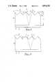
- FIG. 1is a schematic view of a film used in the invention and a light ray entering the film near the top of one of the triangular prisms;
- FIG. 2is a schematic view of a film used in the invention with a light ray entering towards the center of one of the triangular prisms;
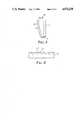
- FIG. 3is a schematic view of a lighting element utilizing the film used in the invention.
- FIG. 4is a schematic view of an alternative embodiment of the film used in the invention utilizing a round format
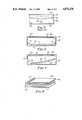
- FIG. 5is a schematic view of a prior art back-lit display
- FIG. 6is a schematic view of a first back-lit display according to the invention.
- FIG. 7is a schematic view of a second back-lit display according to the invention.
- FIG. 8is a schematic view of a third back-lit display according to the invention.
- FIG. 1shows a transparent film having a structured surface 11 and a smooth surface 12. Smooth surface 12 is equipped with a light reflective means 21.
- reflector 21is a vacuum deposited layer of aluminum.
- Structured surface 11has a plurality of triangular prisms such as prism 13.
- Prism 13has sides 14 and 15.
- sides 14 and 15meet at a right angle and, if projected to surface 12, would meet that surface at 45° angles.
- the cross sections of the prismsform right isosceles triangles, with the right angles forming peaks and the legs forming a series of grooves, although other angles may be chosen and will provide reflections of other angles.
- the axes of all the prisms on the filmrun parallel to one another.
- Light beam 16enters film 10 through facet 14 of prism 13 near the intersection of facets 14 and 15. Light beam 16 is refracted and then totally internally reflected off facet 15 of prism 13. After total internal reflection light beam 16 passes through film 10 and is reflected off reflector 21. It then passes through film 10 in the other direction and emerges through facet 19 of prism 17. At that time it is refracted a second time and emerges in a direction substantially perpendicular to incoming beam 16.
- FIG. 2shows light ray 20 entering through facet 14 of prism 13 in a location more distant from the intersection of facets 14 and 15 than was the case with light ray 16 of FIG. 1.
- Light ray 20is refracted upon passing through facet 14 and is totally internally reflected by facet 15. It is then reflected by reflector 21 and emerges through facet 19 of prism 17.
- light ray 20is refracted upon emerging from film 10 and emerges in a direction substantially perpendicular to incoming light ray 20.
- FIGS. 1 and 2An important feature of the invention, as illustrated in FIGS. 1 and 2, relates to the fact that the outgoing light beam always emerges at a predetermined angle relative to the incoming beam.
- film 10may be rotated around an axis running parallel to the axes of the prisms without affecting the direction of the outgoing light beam.
- the height of the prismsis designated H and the thickness of the film, i.e., the distance from surface 12 to the peaks of the prisms is designated T.
- the thickness of the filmi.e., the distance from surface 12 to the peaks of the prisms.
- performancehas been determined to be optimized when the light beam emerges through the prism adjacent to the one through which it enters. This is accomplished when T is equal to 3.2152H.
- His equal to 0.007 inches
- Tshould be 0.225 inches.
- the efficiency of the reflectorwill be reduced because some of the light will not strike the reflecting facet of the prism through which it enters.
- the index of refraction of the filmis 1.495
- the index of the films used in testing the reflective films used in the inventionthe maximum angle that the incoming light ray should make with surface 12 is 13.1°, although angles of as much as 20° have produced adequate and acceptable results. Even greater angles may be used if decreased efficiencies can be tolerated in a given application.
- the film of the inventionhas right isosceles prisms, the sides of which each form a 45° angle with the smooth surface.
- the inventiondoes not require such prisms, however.
- the prismsmay have included angles of sizes other than 90° and need not be isosceles. If an isosceles triangle with an included angle of less than 90° is used, the film will perform similarly to the one described, but the reflected beam will emerge at an angle of less than 90°. Conversely, isosceles prisms with included angles of greater than 90° will cause the reflected beam to emerge at an angle of greater than 90° with respect to the incoming beam.
- FIG. 3shows a light fixture utilizing the film of the present invention.
- the light fixtureincludes right angle reflecting film 30 with a reflector 34, a lens 31, and light source 32.
- Light source 32directs a substantially collimated light at film 30 from angle that will be within the range of angles where film 30 provides its most efficient right angle reflection.
- Lens 31may be any type of lens conventionally used with light fixtures. For example, if the light fixture of FIG. 3 were to be used in an automobile taillight, lens 31 could be a conventional pillow lens which will spread the emitted light to meet established safety standards. In other types of light fixtures, other appropriate lenses may be selected.
- right angle reflector film 30is set an angle to lens 31. This is done so that the light from light source 32 can strike right angle reflector film 30 at an angle of greater than one degree and be reflected perpendicularly to lens 31.
- a light fixture of the type shown in FIG. 3will be much more compact than the conventional light fixtures utilizing conventional parabolic reflectors. This is because the light fixture of FIG. 3 need only be wide enough to accommodate light source 32. Light source 32 may also be made very compact. This is because there is no requirement that it have a large aperture like the light fixture itself. Therefore, light source 32 may utilize a compact reflector, thereby occupying little space itself. If required, more than one light source may be used.
- right angle reflecting film 30is curved as shown in FIG. 3. This is because parabolic light sources such as light source 32 typically do not provide perfectly collimated light. Thus, the flux density of light received by right angle reflector film 30 would vary along the length, with the portion of right angle reflector film 30 which is more distant from light source 32 receiving less light, if right angle reflector 30 were flat. By providing the curvature shown, all portions of right angle reflector film 30 will receive equal flux densities and thus the light fixture will provide more uniform illumination, than would be provided if right angle reflector film 30 were flat. The exact shape of the curve will, of course, depend on the nature of light source 32. If desired, reflecting film 30 could be curved in such a manner that the resulting light fixture would appear brighter on the end more distant from light source 32.
- the efficiency of the light source of FIG. 3may be improved by including a reflector 33 at the end of the light fixture opposite light source 32. This mirror will reflect light that is emitted by light source 32 but does not strike film 30 back into film 30.
- FIG. 4illustrates an alternative embodiment of the film used in the invention.
- a film 10'has a series of prisms such as prism 13'.
- the prisms of FIG. 4are circular and concentric. This is shown schematically by the way prism 13' curves into the location shown as 13".
- a light sourcemay be located at the center of curvature of the concentric prisms. Such a light source should be directed in such a manner as to cause light to strike the film at an angle within the range of angles for which the film provides high efficiency right angle reflection.
- LCDsliquid crystal displays
- LCDsare currently being used as flat panel televisions, automotive instrument panels and low power consumption computer displays. In order to maximize both the esthetic appeal and the readability of such displays uniform illumination is critical.
- FIG. 5Various schemes have been utilized in the prior art to provide greater uniformity of illumination in a back-lit display.
- a housing 40defines an optical cavity 42.
- Optical cavity 42has an optical window 44.
- a diffuser 46In optical window 44 is a diffuser 46 and a display 48.
- Inside optical cavity 42is a light source 50.
- the interior walls 52 of housing 40would be reflectorized.
- diffuser 46is tapered so that it is thicker adjacent light source 50 than it is at its edges. Since diffuser 46 is thicker close to light source 50, more of the light in that region is absorbed than is absorbed at the edges. The result is a more uniform level of illumination through display 48.
- the tapered diffuser of FIG. 5There are two disadvantages to the use of the tapered diffuser of FIG. 5.
- the first disadvantageis the difficulty of fabrication of such a tapered diffuser.
- the second disadvantageis that, since the uniformity of illumination is achieved by absorbing more of the light in some regions, a greater total amount of light must be supplied to achieve the desired brightness level.
- FIG. 6shows a back-lit display according to the invention.
- the embodiment of FIG. 6includes a housing 60 defining an optical cavity 62.
- Optical cavity 62has an optical window 64.
- a diffuser 66In optical window 64 are a diffuser 66 and a display 68.
- right angle film 70Inside optical cavity 62 are right angle film 70 having structured surface 71 and reflectorized surface 72 and light sources 74 and 76 at the edges of right angle film 70.
- Light sources 74 and 76are designed and positioned so as to emit substantially collimated beams of light in a direction almost parallel to planar surface 72 of right angle reflector film 70.
- the use of light sources on both sides of right angle reflector film 70helps to provide uniform illumination over the entire area of display 68.
- Light sources 74 and 76could be any type of lighting element.
- One possibilityis the use of LEDs. LEDs are particularly advantageous for an application in which low power consumption is desired. An example of such an application is a display for a portable
- FIG. 7illustrates another embodiment of the present invention.
- a housing 80defines an optical cavity 82.
- Optical cavity 82has an optical window 84.
- diffusing film 86 and display 88are diffusing film 86 and display 88.
- right angle reflector film 90having structured surface 91 and planar reflectorized surface 92.
- light source 94positioned at one edge of right angle reflector film 90.
- Light source 94is arranged to direct light towards right angle reflector film 90 in a direction almost parallel to planar surface 92, so that partially collimated light will be directed through diffuser 86 and display 88.
- Right angle reflector film 90is curved in order to produce a uniform illumination over the entire area of optical window 84.
- the back-lit displays of FIG. 6 and FIG. 7are advantageous over the prior art display of FIG. 5 in that they do not require the tapered diffuser of FIG. 5 and they produce uniform lighting without intentionally discarding any of the available light. Thus they may be more easily fabricated and will not waste energy by intentionally discarding light. Furthermore the displays of the invention may be made very thin, making them compact and allowing them to be light in weight.
- FIG. 8 of the present applicationshows another embodiment of the present invention.
- the light sourceincludes light emitter 100 and right angle film 102.
- Light emitter 100is preferably effectively a collimated point source. It may be, for example, an incandescent light with a collimating reflector, an LED or a laser. Light from light emitter 100 travels in a direction that is almost parallel to the smooth surface of right angle film 102.
- right angle film 102The effect of right angle film 102 is to spread the light from light emitter 100 so the light source for right angle film 104 is a line source. The light leaves right angle film 102 in a direction almost parallel to the smooth surface of right angle film 104. After reflection by right angle film 104 it passes through diffuser 106 and display 108. By properly choosing the curvature of films 102 and 104 a uniform level of illumination may be achieved over all of display 108.
Landscapes
- Physics & Mathematics (AREA)
- General Physics & Mathematics (AREA)
- Optics & Photonics (AREA)
- Engineering & Computer Science (AREA)
- General Engineering & Computer Science (AREA)
- Theoretical Computer Science (AREA)
- Life Sciences & Earth Sciences (AREA)
- Microelectronics & Electronic Packaging (AREA)
- Pest Control & Pesticides (AREA)
- General Health & Medical Sciences (AREA)
- Environmental Sciences (AREA)
- Wood Science & Technology (AREA)
- Plant Pathology (AREA)
- Health & Medical Sciences (AREA)
- Agronomy & Crop Science (AREA)
- Zoology (AREA)
- Dentistry (AREA)
- Illuminated Signs And Luminous Advertising (AREA)
- Liquid Crystal (AREA)
- Devices For Indicating Variable Information By Combining Individual Elements (AREA)
- Planar Illumination Modules (AREA)
- Optical Elements Other Than Lenses (AREA)
Abstract
Description
This is a continuation-in-part of application Ser. No. 030,033 filed Mar. 24, 1987, now U.S. Pat. No. 4,799,137.
The present invention relates to optical films and more particularly to back-lit displays utilizing an optical film that will reflect light at a predetermined constant angle relative to the angle of incidence.
In many situations a light source is desired to provide a collimated beam of light. The typical method of providing such a collimated beam of light is to utilize a parabolic reflector. Two disadvantages exist in the use of parabolic reflectors, however. One disadvantage relates to the size of a parabolic reflector. If the light source is to have a large aperture, a parabolic reflector must be relatively deep, and thus enclose a large volume. This is particularly true if the parabolic reflector has a relatively short focal length. In situations where space is limited, such as automobile taillights or back-lit displays, the size of such reflectors can be a significant disadvantage.
A second disadvantage lies in the existence of "hot" spots in the light pattern produced by a parabolic reflector. Such hot spots arise from the fact that the parabolic reflector is more efficient at gathering light near the center than at the edges. A parabolic reflector, thus, is not optimum for use in a light source where a uniform intensity is desired.
One alternative to the use of a parabolic reflector is shown in U.S. Pat. No. 4,789,921, commonly assigned herewith. In the approach shown in that application a reflector has Fresnel structures that cause the reflector to have the properties of a parabolic reflector when it is formed into the shape of a cone. That approach allows a reflector to be less deep than the equivalent conventional parabolic reflector, but does not solve the problem of providing a uniform intensity over the entire light source.
A back-lit display according to the invention has a housing defining an optical cavity having an optical window. Inside the optical cavity is a light reflecting film having a structured surface and a smooth surface. The structured surface has thereon a plurality of triangular prisms. A light reflecting means is adjacent said smooth surface. A light source is positioned to emit light such that the light will enter the film in a direction that is almost parallel to the smooth surface. The actual display means is positioned in the optical window.
FIG. 1 is a schematic view of a film used in the invention and a light ray entering the film near the top of one of the triangular prisms;
FIG. 2 is a schematic view of a film used in the invention with a light ray entering towards the center of one of the triangular prisms;
FIG. 3 is a schematic view of a lighting element utilizing the film used in the invention;
FIG. 4 is a schematic view of an alternative embodiment of the film used in the invention utilizing a round format;
FIG. 5 is a schematic view of a prior art back-lit display;
FIG. 6 is a schematic view of a first back-lit display according to the invention;
FIG. 7 is a schematic view of a second back-lit display according to the invention; and
FIG. 8 is a schematic view of a third back-lit display according to the invention.
FIG. 1 shows a transparent film having a structured surface 11 and asmooth surface 12.Smooth surface 12 is equipped with a lightreflective means 21. In thepreferred embodiment reflector 21 is a vacuum deposited layer of aluminum.
Structured surface 11 has a plurality of triangular prisms such asprism 13. Prism 13 hassides sides surface 12, would meet that surface at 45° angles. Thus, in the preferred embodiment the cross sections of the prisms form right isosceles triangles, with the right angles forming peaks and the legs forming a series of grooves, although other angles may be chosen and will provide reflections of other angles.
FIG. 2 showslight ray 20 entering throughfacet 14 ofprism 13 in a location more distant from the intersection offacets light ray 16 of FIG. 1.Light ray 20 is refracted upon passing throughfacet 14 and is totally internally reflected byfacet 15. It is then reflected byreflector 21 and emerges throughfacet 19 ofprism 17. As withlight ray 16,light ray 20 is refracted upon emerging fromfilm 10 and emerges in a direction substantially perpendicular to incominglight ray 20.
An important feature of the invention, as illustrated in FIGS. 1 and 2, relates to the fact that the outgoing light beam always emerges at a predetermined angle relative to the incoming beam. Thus,film 10 may be rotated around an axis running parallel to the axes of the prisms without affecting the direction of the outgoing light beam.
Returning to FIG. 1 the height of the prisms is designated H and the thickness of the film, i.e., the distance fromsurface 12 to the peaks of the prisms is designated T. In the preferred embodiment, where the light is intended to emerge in a direction perpendicular to the incoming light beam, performance has been determined to be optimized when the light beam emerges through the prism adjacent to the one through which it enters. This is accomplished when T is equal to 3.2152H. Thus if H is equal to 0.007 inches, T should be 0.225 inches. In spite of the fact that this ratio would provide optimum performance, however, films according to the invention have been found to perform adequately when deviating from this ratio.
If the direction of the incoming ray of light deviates by too great an extent from parallel tosurface 12, the efficiency of the reflector will be reduced because some of the light will not strike the reflecting facet of the prism through which it enters. Assuming that the index of refraction of the film is 1.495, the index of the films used in testing the reflective films used in the invention, the maximum angle that the incoming light ray should make withsurface 12 is 13.1°, although angles of as much as 20° have produced adequate and acceptable results. Even greater angles may be used if decreased efficiencies can be tolerated in a given application.
If the angle between the incoming light andsurface 12 becomes too small, efficiency will again be reduced because most of the light will enter near the peaks of the prism where small deviations from sharpness are very important. Furthermore, small deviations in the height of the prisms become more important at narrow entry angles. For this reason, angles less than 1° are not generally recommended, although theoretically possible.
As described, the film of the invention has right isosceles prisms, the sides of which each form a 45° angle with the smooth surface. The invention does not require such prisms, however. The prisms may have included angles of sizes other than 90° and need not be isosceles. If an isosceles triangle with an included angle of less than 90° is used, the film will perform similarly to the one described, but the reflected beam will emerge at an angle of less than 90°. Conversely, isosceles prisms with included angles of greater than 90° will cause the reflected beam to emerge at an angle of greater than 90° with respect to the incoming beam.
FIG. 3 shows a light fixture utilizing the film of the present invention. The light fixture includes rightangle reflecting film 30 with areflector 34, alens 31, andlight source 32.Light source 32 directs a substantially collimated light atfilm 30 from angle that will be within the range of angles wherefilm 30 provides its most efficient right angle reflection.Lens 31 may be any type of lens conventionally used with light fixtures. For example, if the light fixture of FIG. 3 were to be used in an automobile taillight,lens 31 could be a conventional pillow lens which will spread the emitted light to meet established safety standards. In other types of light fixtures, other appropriate lenses may be selected. As may be seen in FIG. 3, rightangle reflector film 30 is set an angle tolens 31. This is done so that the light fromlight source 32 can strike rightangle reflector film 30 at an angle of greater than one degree and be reflected perpendicularly tolens 31.
A light fixture of the type shown in FIG. 3 will be much more compact than the conventional light fixtures utilizing conventional parabolic reflectors. This is because the light fixture of FIG. 3 need only be wide enough to accommodatelight source 32.Light source 32 may also be made very compact. This is because there is no requirement that it have a large aperture like the light fixture itself. Therefore,light source 32 may utilize a compact reflector, thereby occupying little space itself. If required, more than one light source may be used.
In the preferred embodiment rightangle reflecting film 30 is curved as shown in FIG. 3. This is because parabolic light sources such aslight source 32 typically do not provide perfectly collimated light. Thus, the flux density of light received by rightangle reflector film 30 would vary along the length, with the portion of rightangle reflector film 30 which is more distant fromlight source 32 receiving less light, ifright angle reflector 30 were flat. By providing the curvature shown, all portions of rightangle reflector film 30 will receive equal flux densities and thus the light fixture will provide more uniform illumination, than would be provided if rightangle reflector film 30 were flat. The exact shape of the curve will, of course, depend on the nature oflight source 32. If desired, reflectingfilm 30 could be curved in such a manner that the resulting light fixture would appear brighter on the end more distant fromlight source 32.
The efficiency of the light source of FIG. 3 may be improved by including areflector 33 at the end of the light fixture oppositelight source 32. This mirror will reflect light that is emitted bylight source 32 but does not strikefilm 30 back intofilm 30.
FIG. 4 illustrates an alternative embodiment of the film used in the invention. In the embodiment of FIG. 4 a film 10' has a series of prisms such as prism 13'. Rather than being disposed linearly, as in the previously described embodiments, the prisms of FIG. 4 are circular and concentric. This is shown schematically by the way prism 13' curves into the location shown as 13". A light source may be located at the center of curvature of the concentric prisms. Such a light source should be directed in such a manner as to cause light to strike the film at an angle within the range of angles for which the film provides high efficiency right angle reflection.
Uniform lighting intensity is particularly important for back-lit display panels. An important type of such display panels are liquid crystal displays (LCDs). LCDs are currently being used as flat panel televisions, automotive instrument panels and low power consumption computer displays. In order to maximize both the esthetic appeal and the readability of such displays uniform illumination is critical.
Various schemes have been utilized in the prior art to provide greater uniformity of illumination in a back-lit display. One such scheme is shown in FIG. 5. In the prior art back-lit display of FIG. 5 ahousing 40 defines anoptical cavity 42.Optical cavity 42 has anoptical window 44. Inoptical window 44 is adiffuser 46 and adisplay 48. Insideoptical cavity 42 is a light source 50. Typically theinterior walls 52 ofhousing 40 would be reflectorized. As may be seen from FIG. 5,diffuser 46 is tapered so that it is thicker adjacent light source 50 than it is at its edges. Sincediffuser 46 is thicker close to light source 50, more of the light in that region is absorbed than is absorbed at the edges. The result is a more uniform level of illumination throughdisplay 48.
There are two disadvantages to the use of the tapered diffuser of FIG. 5. The first disadvantage is the difficulty of fabrication of such a tapered diffuser. The second disadvantage is that, since the uniformity of illumination is achieved by absorbing more of the light in some regions, a greater total amount of light must be supplied to achieve the desired brightness level.
FIG. 6 shows a back-lit display according to the invention. The embodiment of FIG. 6 includes ahousing 60 defining anoptical cavity 62.Optical cavity 62 has anoptical window 64. Inoptical window 64 are adiffuser 66 and adisplay 68. Insideoptical cavity 62 are right angle film 70 having structured surface 71 andreflectorized surface 72 andlight sources Light sources planar surface 72 of right angle reflector film 70. The use of light sources on both sides of right angle reflector film 70 helps to provide uniform illumination over the entire area ofdisplay 68.Light sources
FIG. 7 illustrates another embodiment of the present invention. In FIG. 7 ahousing 80 defines anoptical cavity 82.Optical cavity 82 has anoptical window 84. Inoptical window 84 are diffusingfilm 86 anddisplay 88. Insideoptical cavity 82 are rightangle reflector film 90 having structuredsurface 91 andplanar reflectorized surface 92. Also insideoptical cavity 82 islight source 94 positioned at one edge of rightangle reflector film 90.Light source 94 is arranged to direct light towards rightangle reflector film 90 in a direction almost parallel toplanar surface 92, so that partially collimated light will be directed throughdiffuser 86 anddisplay 88. Rightangle reflector film 90 is curved in order to produce a uniform illumination over the entire area ofoptical window 84.
The back-lit displays of FIG. 6 and FIG. 7 are advantageous over the prior art display of FIG. 5 in that they do not require the tapered diffuser of FIG. 5 and they produce uniform lighting without intentionally discarding any of the available light. Thus they may be more easily fabricated and will not waste energy by intentionally discarding light. Furthermore the displays of the invention may be made very thin, making them compact and allowing them to be light in weight.
FIG. 8 of the present application shows another embodiment of the present invention. In the embodiment of FIG. 8 the light source includeslight emitter 100 andright angle film 102.Light emitter 100 is preferably effectively a collimated point source. It may be, for example, an incandescent light with a collimating reflector, an LED or a laser. Light fromlight emitter 100 travels in a direction that is almost parallel to the smooth surface ofright angle film 102.
The effect ofright angle film 102 is to spread the light fromlight emitter 100 so the light source forright angle film 104 is a line source. The light leavesright angle film 102 in a direction almost parallel to the smooth surface ofright angle film 104. After reflection byright angle film 104 it passes throughdiffuser 106 anddisplay 108. By properly choosing the curvature offilms 102 and 104 a uniform level of illumination may be achieved over all ofdisplay 108.
Claims (18)
1. A back-lit display comprising:
a housing defining an optical cavity having an optical window;
a light reflecting film in said optical cavity, said light reflecting film having first and second major surfaces, said first surface being a structured surface having a plurality of triangular prisms thereon and said second surface being a smooth surface, and a light reflecting means adjacent said second surface for reflecting light approaching said second surface from said first surface;
a first light source positioned so that light rays approach said film in a direction that is almost parallel to said second surface of said film; and
display means in said optical window.
2. The back-lit display of claim 1 wherein said display means includes a liquid crystal display.
3. The back-lit display of claim 1 further comprising light diffusing means between said reflective film and said display means.
4. The back-lit display of claim 1 wherein said light source is positioned so that light rays approach said film in a direction that makes an angle of no more than 20° with said second surface.
5. The back-lit display of claim 1 further comprising a second light source positioned so that light rays approach said film in a direction that is almost parallel to said second surface of said film, said first and second light source being positioned adjacent opposite ends of said film.
6. The back-lit display of claim 5 wherein said display means includes a liquid crystal display.
7. The back-lit display of claim 5 further comprising light diffusing means between said reflective film and said display means.
8. The back-lit display of claim 5 wherein both of said light sources are positioned so that light rays approach said film in a direction that makes an angle of no more than 20° with said second surface.
9. The back-lit display of claim 8 wherein said display means includes a liquid crystal display.
10. The back-lit display of claim 9 further comprising light diffusing means between said reflective film and said display means.
11. The back-lit display of claim 1 wherein said light source is positioned adjacent one end of said film and said film curves so that said end of said film adjacent said light source is more distant from said display means than the opposite end of said film.
12. The back-lit display of claim 11 wherein said display means includes a liquid crystal display.
13. The back-lit display of claim 11 further comprising light diffusing means between said reflective film and said display means.
14. The back-lit display of claim 11 wherein said light source is positioned so that light rays approach said film in a direction that makes an angle of no more than 20° with said second surface.
15. The back-lit display of claim 14 wherein said display means includes a liquid crystal display.
16. The back-lit display of claim 15 further comprising light diffusing means between said reflective film and said display means.
17. The back-lit display of claim 1 wherein said light source comprises:
a light reflecting film having first and second major surfaces, said first surface being a structured surface having a plurality of triangular prisms thereon and said second surface being a smooth surface and a light reflecting means adjacent said second surface for reflecting light approaching said second surface from said first surface; and
a light emitting means positioned so that light rays approach said light source reflecting film in a direction that is almost parallel to said second surface of said light source reflecting film.
18. The back-lit display of claim 17 wherein said display means includes a liquid crystal display.
Priority Applications (8)
| Application Number | Priority Date | Filing Date | Title |
|---|---|---|---|
| US07/292,762US4874228A (en) | 1987-03-24 | 1989-01-03 | Back-lit display |
| CA002004047ACA2004047A1 (en) | 1989-01-03 | 1989-11-28 | Back-lit display |
| MYPI89001672AMY104485A (en) | 1989-01-03 | 1989-12-01 | Back-lit display. |
| EP19890313423EP0377309A3 (en) | 1989-01-03 | 1989-12-21 | Back-lit display |
| JP01334624AJP3074482B2 (en) | 1989-01-03 | 1989-12-22 | Backlight indicator |
| JP2000026018AJP3591825B2 (en) | 1989-01-03 | 2000-02-03 | Backlighting for use in displays |
| JP2004051380AJP2004185036A (en) | 1989-01-03 | 2004-02-26 | Backlighting used for display |
| JP2005190442AJP2005331969A (en) | 1989-01-03 | 2005-06-29 | Back illumination to be used for display unit |
Applications Claiming Priority (2)
| Application Number | Priority Date | Filing Date | Title |
|---|---|---|---|
| US07/030,033US4799137A (en) | 1987-03-24 | 1987-03-24 | Reflective film |
| US07/292,762US4874228A (en) | 1987-03-24 | 1989-01-03 | Back-lit display |
Related Parent Applications (1)
| Application Number | Title | Priority Date | Filing Date |
|---|---|---|---|
| US07/030,033Continuation-In-PartUS4799137A (en) | 1987-03-24 | 1987-03-24 | Reflective film |
Publications (1)
| Publication Number | Publication Date |
|---|---|
| US4874228Atrue US4874228A (en) | 1989-10-17 |
Family
ID=23126081
Family Applications (1)
| Application Number | Title | Priority Date | Filing Date |
|---|---|---|---|
| US07/292,762Expired - LifetimeUS4874228A (en) | 1987-03-24 | 1989-01-03 | Back-lit display |
Country Status (5)
| Country | Link |
|---|---|
| US (1) | US4874228A (en) |
| EP (1) | EP0377309A3 (en) |
| JP (4) | JP3074482B2 (en) |
| CA (1) | CA2004047A1 (en) |
| MY (1) | MY104485A (en) |
Cited By (96)
| Publication number | Priority date | Publication date | Assignee | Title |
|---|---|---|---|---|
| US4947300A (en)* | 1989-01-03 | 1990-08-07 | Wen Hung S | Character and numeral displaying device |
| US4971425A (en)* | 1987-08-10 | 1990-11-20 | Nissan Motor Co., Ltd. | Display device |
| US4994941A (en)* | 1989-01-03 | 1991-02-19 | Wen Hung Sheng | Sign of character and figure |
| US5014174A (en)* | 1988-02-06 | 1991-05-07 | Joung H. Won | Reflection sheet for lighting or color-lighting |
| US5040878A (en)* | 1990-01-26 | 1991-08-20 | Dimension Technologies, Inc. | Illumination for transmissive displays |
| US5054885A (en)* | 1988-10-11 | 1991-10-08 | Minnesota Mining And Manfuacturing Company | Light fixture including a partially collimated beam of light and reflective prisms having peaks lying on a curved surface |
| US5070431A (en)* | 1989-08-03 | 1991-12-03 | Pioneer Electronic Corporation | Display board illuminating device for passive displays |
| US5150966A (en)* | 1990-09-19 | 1992-09-29 | Minnesota Mining And Manufacturing Company | Uniform intensity profile catadioptric lens |
| EP0490279A3 (en)* | 1990-12-08 | 1992-11-25 | Minnesota Mining And Manufacturing Company | Light box |
| US5190370A (en)* | 1991-08-21 | 1993-03-02 | Minnesota Mining And Manufacturing Company | High aspect ratio lighting element |
| US5193899A (en)* | 1989-04-25 | 1993-03-16 | Mitsubishi Rayon Co., Ltd. | Planar light-source device and illumination apparatus using the same |
| US5195818A (en)* | 1990-12-08 | 1993-03-23 | Minnesota Mining And Manufacturing Company | Elongated lamp |
| US5243506A (en)* | 1991-06-17 | 1993-09-07 | Tir Systems Ltd. | High aspect ratio light emitter having high uniformity and directionality |
| US5339382A (en)* | 1993-02-23 | 1994-08-16 | Minnesota Mining And Manufacturing Company | Prism light guide luminaire with efficient directional output |
| US5353735A (en)* | 1991-04-23 | 1994-10-11 | Yazaki Corporation | Indicating instrument system |
| US5381309A (en)* | 1993-09-30 | 1995-01-10 | Honeywell Inc. | Backlit display with enhanced viewing properties |
| US5396350A (en)* | 1993-11-05 | 1995-03-07 | Alliedsignal Inc. | Backlighting apparatus employing an array of microprisms |
| US5428468A (en)* | 1993-11-05 | 1995-06-27 | Alliedsignal Inc. | Illumination system employing an array of microprisms |
| US5471348A (en)* | 1994-05-13 | 1995-11-28 | Minnesota Mining And Manufacturing Company | Directed reflection optical device |
| US5479275A (en)* | 1993-12-03 | 1995-12-26 | Ois Optical Imaging Systems, Inc. | Backlit liquid crystal display with integral collimating, refracting, and reflecting means which refracts and collimates light from a first light source and reflects light from a second light source |
| US5502626A (en)* | 1994-06-17 | 1996-03-26 | Honeywell Inc. | High efficiency fluorescent lamp device |
| US5521725A (en)* | 1993-11-05 | 1996-05-28 | Alliedsignal Inc. | Illumination system employing an array of microprisms |
| US5526146A (en)* | 1993-06-24 | 1996-06-11 | International Business Machines Corporation | Back-lighting system for transmissive display |
| US5555329A (en)* | 1993-11-05 | 1996-09-10 | Alliesignal Inc. | Light directing optical structure |
| US5590945A (en)* | 1995-07-26 | 1997-01-07 | Industrial Devices, Inc. | Illuminated line of light using point light source |
| US5598281A (en)* | 1993-11-19 | 1997-01-28 | Alliedsignal Inc. | Backlight assembly for improved illumination employing tapered optical elements |
| US5608550A (en)* | 1994-06-24 | 1997-03-04 | Minnesota Mining And Manufacturing Company | Front-lit liquid crystal display having brightness enhancing film with microridges which directs light through the display to a reflector |
| US5629784A (en)* | 1994-04-12 | 1997-05-13 | Ois Optical Imaging Systems, Inc. | Liquid crystal display with holographic diffuser and prism sheet on viewer side |
| US5661839A (en)* | 1996-03-22 | 1997-08-26 | The University Of British Columbia | Light guide employing multilayer optical film |
| US5771328A (en)* | 1995-03-03 | 1998-06-23 | Minnesota Mining And Manufacturing Company | Light directing film having variable height structured surface and light directing article constructed therefrom |
| US5825636A (en)* | 1995-03-01 | 1998-10-20 | International Manufacturing And Engineering Services Co., Ltd. | Planar luminescent device and planar luminescent element |
| US5831585A (en)* | 1995-02-08 | 1998-11-03 | Matsushita Electric Industrial Co., Ltd. | Light transmission screen |
| US5833360A (en)* | 1996-10-17 | 1998-11-10 | Compaq Computer Corporation | High efficiency lamp apparatus for producing a beam of polarized light |
| US5919551A (en)* | 1996-04-12 | 1999-07-06 | 3M Innovative Properties Company | Variable pitch structured optical film |
| US5977942A (en)* | 1996-12-20 | 1999-11-02 | Compaq Computer Corporation | Multiplexed display element sequential color LCD panel |
| USRE36654E (en) | 1989-03-28 | 2000-04-11 | In Focus Systems, Inc. | Stacked LCD color display |
| US6100952A (en)* | 1997-06-04 | 2000-08-08 | Korry Electronics Co. | NVG-compatible AMLCD backlight having a ridged prismatic TIR with an embedded diffuser doped with an IR absorbing dye |
| US6111622A (en)* | 1993-03-12 | 2000-08-29 | Ois Optical Imaging Systems, Inc. | Day/night backlight for a liquid crystal display |
| US6129439A (en)* | 1993-11-05 | 2000-10-10 | Alliedsignal Inc. | Illumination system employing an array of multi-faceted microprisms |
| US6166787A (en)* | 1998-03-17 | 2000-12-26 | Motorola, Inc. | Optical display device having prismatic film for enhanced viewing |
| US6191833B1 (en)* | 1998-12-24 | 2001-02-20 | Hitachi, Ltd. | Liquid crystal display device having reflection film between prism sheet and liquid crystal panel |
| US6220713B1 (en) | 1998-10-23 | 2001-04-24 | Compaq Computer Corporation | Projection lens and system |
| US6243152B1 (en) | 1996-12-17 | 2001-06-05 | Duke University | Contrast polymer dispersed liquid crystal projection display system |
| US6285425B1 (en) | 1998-06-29 | 2001-09-04 | Motorola, Inc. | Ridged reflector for an optical display having a curved and a planar facet for each ridge |
| US6285426B1 (en) | 1998-07-06 | 2001-09-04 | Motorola, Inc. | Ridged reflector having optically transmissive properties for an optical display device |
| US6313893B1 (en) | 1996-12-27 | 2001-11-06 | Duke University | Compensation for DC balancing of liquid crystal displays |
| US6347874B1 (en) | 2000-02-16 | 2002-02-19 | 3M Innovative Properties Company | Wedge light extractor with risers |
| US20020051866A1 (en)* | 2000-08-18 | 2002-05-02 | Reflexite Corporation | Differentially cured materials and process for forming same |
| US6483612B2 (en) | 1998-04-15 | 2002-11-19 | Duke University | Projection screen apparatus including holographic optical element |
| US20030007229A1 (en)* | 1994-12-22 | 2003-01-09 | Handschy Mark A. | Optics arrangements including light source arrangements for an active matrix liquid crystal image generator |
| US6525750B1 (en) | 1996-03-08 | 2003-02-25 | Duke University | Projection display for computers |
| US6572233B1 (en)* | 1998-10-14 | 2003-06-03 | Gentex Corporation | Rearview mirror with display |
| US6576887B2 (en) | 2001-08-15 | 2003-06-10 | 3M Innovative Properties Company | Light guide for use with backlit display |
| US6575584B1 (en)* | 1999-05-28 | 2003-06-10 | Universite De Liege | Light guiding plate with internal micro-prisms |
| US6592234B2 (en) | 2001-04-06 | 2003-07-15 | 3M Innovative Properties Company | Frontlit display |
| EP1327102A2 (en)* | 2000-10-11 | 2003-07-16 | Screen Technology Limited | Beam expansion |
| US6612729B1 (en) | 2000-03-16 | 2003-09-02 | 3M Innovative Properties Company | Illumination device |
| US6621973B1 (en) | 2000-03-16 | 2003-09-16 | 3M Innovative Properties Company | Light guide with protective outer sleeve |
| US6637918B2 (en)* | 2000-10-23 | 2003-10-28 | Valeo Vision | Lighting or indicator device for a motor vehicle |
| US20030206342A1 (en)* | 1993-05-12 | 2003-11-06 | Bright View Technologies, Inc. | Micro-lens array based light transmission screen |
| US20030210462A1 (en)* | 1998-04-15 | 2003-11-13 | Bright View Technologies, Inc. | Micro-lens array based light transmitting screen with tunable gain |
| US6663262B2 (en)* | 2001-09-10 | 2003-12-16 | 3M Innovative Properties Company | Backlighting transmissive displays |
| US20040008411A1 (en)* | 1998-04-15 | 2004-01-15 | Bright View Technologies, Inc. | Micro-lens array based light transmitting screen with high resolution and low imaging artifacts |
| US6681509B1 (en) | 2000-09-06 | 2004-01-27 | France Jean | Artistic display |
| US20040017612A1 (en)* | 1998-04-15 | 2004-01-29 | Bright View Technologies, Inc. | Micro-lens array with precisely aligned aperture mask and methods of producing same |
| US6738051B2 (en) | 2001-04-06 | 2004-05-18 | 3M Innovative Properties Company | Frontlit illuminated touch panel |
| US20040095742A1 (en)* | 2002-11-19 | 2004-05-20 | Toppoly Optoelectronics | Plane lighting structure |
| US6746122B2 (en) | 1996-10-17 | 2004-06-08 | Duke University | Image projection system engine assembly |
| US6755534B2 (en) | 2001-08-24 | 2004-06-29 | Brookhaven Science Associates | Prismatic optical display |
| US20040141304A1 (en)* | 2002-11-19 | 2004-07-22 | Hideaki Nagakubo | Illumination device and liquid crystal display device |
| US20040156199A1 (en)* | 2002-09-23 | 2004-08-12 | Nelson Rivas | LED lighting apparatus |
| US6788460B2 (en) | 1998-04-15 | 2004-09-07 | Duke University | Projection screen apparatus |
| US20040190102A1 (en)* | 2000-08-18 | 2004-09-30 | Mullen Patrick W. | Differentially-cured materials and process for forming same |
| US20040246599A1 (en)* | 2003-05-02 | 2004-12-09 | Reflexite Corporation | Light-redirecting optical structures |
| US20050141243A1 (en)* | 2000-08-18 | 2005-06-30 | Reflexite Corporation | Differentially-cured materials and process for forming same |
| US20060038666A1 (en)* | 2004-08-22 | 2006-02-23 | Wiegner Thomas F | Instrument viewing display system for motorcycles |
| US7374305B2 (en)* | 1995-06-27 | 2008-05-20 | Solid State Opto Limited | Light emitting panel assemblies |
| US20080192507A1 (en)* | 2006-01-21 | 2008-08-14 | Hon Hai Precision Industry Co., Ltd. | Edge type backlight module having a reflective plate |
| US7513672B2 (en) | 1995-06-27 | 2009-04-07 | Solid State Opto Limited | Light emitting panel assemblies |
| US20090279280A1 (en)* | 2004-12-16 | 2009-11-12 | David John Bottomley | Structured optical film |
| US20100238658A1 (en)* | 2009-03-21 | 2010-09-23 | Fu Zhun Precision Industry (Shen Zhen) Co., Ltd. | Led lamp |
| US20110063835A1 (en)* | 2002-09-23 | 2011-03-17 | Nelson Rivas | Led lighting apparatus |
| US20110156588A1 (en)* | 2009-12-28 | 2011-06-30 | Brant Gregory S | Vehicle lighting display system |
| US20110216521A1 (en)* | 2010-03-05 | 2011-09-08 | Southpac Trust International Inc., Trustee of the LDH Trust | Light diffusion and condensing fixture |
| CN103133941A (en)* | 2011-12-01 | 2013-06-05 | 扬升照明股份有限公司 | Backlight module |
| US8545048B2 (en)* | 2011-05-13 | 2013-10-01 | Southern Taiwan University | LED illumination structure without light guide plate |
| US9091411B2 (en) | 2012-11-02 | 2015-07-28 | Osram Sylvania Inc. | Illumination techniques and devices |
| US9285531B2 (en) | 2008-08-08 | 2016-03-15 | 3M Innovative Properties Company | Lightguide having a viscoelastic layer for managing light |
| US9285634B2 (en) | 2012-11-27 | 2016-03-15 | Samsung Display Co., Ltd. | Display device |
| US20160312965A1 (en)* | 2014-01-02 | 2016-10-27 | Koninklijke Philips N.V. | Light emitting module |
| CN107221266A (en)* | 2017-07-05 | 2017-09-29 | 佛山杰致信息科技有限公司 | A kind of New LED advertising lamp box |
| DE102008057625B4 (en)* | 2008-11-10 | 2019-02-21 | Automotive Lighting Reutlingen Gmbh | Reflector for a motor vehicle lighting device and motor vehicle lighting device |
| US10228507B2 (en) | 2008-07-10 | 2019-03-12 | 3M Innovative Properties Company | Light source and optical article including viscoelastic lightguide disposed on a substrate |
| US10437104B2 (en)* | 2016-10-13 | 2019-10-08 | Japan Display Inc. | Illumination device and display device |
| US10950743B2 (en) | 2019-05-02 | 2021-03-16 | Stmicroelectronics (Research & Development) Limited | Time of flight (TOF) sensor with transmit optic providing for reduced parallax effect |
| US11169306B1 (en)* | 2021-04-08 | 2021-11-09 | Mark Joseph Oneill | Curvilinear prismatic film which eliminates glare and reduces front-surface reflections for solar panels and other surfaces |
Families Citing this family (21)
| Publication number | Priority date | Publication date | Assignee | Title |
|---|---|---|---|---|
| US5816677A (en)* | 1905-03-01 | 1998-10-06 | Canon Kabushiki Kaisha | Backlight device for display apparatus |
| JPH04179989A (en)* | 1990-11-14 | 1992-06-26 | Takenaka Komuten Co Ltd | Illuminating device |
| JP2557409Y2 (en)* | 1991-05-07 | 1997-12-10 | パイオニア株式会社 | Grill lighting structure |
| FR2678758B1 (en)* | 1991-07-02 | 1993-10-22 | Aupem | SIDE LIGHTING LIGHT BOX AND DIFFUSING FILM. |
| FI91810C (en)* | 1992-08-18 | 1994-08-10 | Nokia Mobile Phones Ltd | light Controller |
| GB2276751B (en)* | 1993-04-01 | 1997-01-22 | Karvan Technology Ltd | Display module |
| JPH0794008A (en)* | 1993-09-24 | 1995-04-07 | Chiyatani Sangyo Kk | Flat lighting device |
| GB2310525A (en)* | 1996-02-24 | 1997-08-27 | Ronnie Revell | Illuminated display device |
| GB0006327D0 (en)* | 2000-03-16 | 2000-05-03 | 3M Innovative Properties Co | Light guides suitable for illuminated displays |
| US6893135B2 (en) | 2000-03-16 | 2005-05-17 | 3M Innovative Properties Company | Light guides suitable for illuminated displays |
| GB0123813D0 (en) | 2001-10-03 | 2001-11-21 | 3M Innovative Properties Co | Light-guide lights suitable for use in illuminated displays |
| GB0123815D0 (en)* | 2001-10-03 | 2001-11-21 | 3M Innovative Properties Co | Light-guide lights providing a substantially monochromatic beam |
| KR20040047084A (en)* | 2002-11-29 | 2004-06-05 | 태원전기산업 (주) | Display System Of A Lamp |
| EP1586813A1 (en) | 2004-04-16 | 2005-10-19 | 3M Innovative Properties Company | Light box |
| GB0419391D0 (en)* | 2004-09-01 | 2004-10-06 | 3M Innovative Properties Co | Luminaire comprising a light box |
| US8594742B2 (en) | 2006-06-21 | 2013-11-26 | Symbol Technologies, Inc. | System and method for monitoring a mobile device |
| AU2007354904B2 (en) | 2007-06-14 | 2014-06-26 | Avery Dennison Corporation | Illuminated graphical and information display |
| DE202009013088U1 (en)* | 2009-09-29 | 2011-02-24 | Zumtobel Lighting Gmbh | Illumination arrangement with light influencing element |
| US8228463B2 (en)* | 2009-11-18 | 2012-07-24 | 3M Innovative Properties Company | Passive daylight-coupled backlight with turning film having prisms with chaos for sunlight viewable displays |
| US8384852B2 (en) | 2010-11-22 | 2013-02-26 | 3M Innovative Properties Company | Hybrid daylight-coupled backlights for sunlight viewable displays |
| JP6592375B2 (en)* | 2016-02-24 | 2019-10-16 | 株式会社ジャパンディスプレイ | Display device |
Citations (7)
| Publication number | Priority date | Publication date | Assignee | Title |
|---|---|---|---|---|
| DE2511252A1 (en)* | 1974-03-15 | 1975-09-18 | Seiko Instr & Electronics | OPTICAL REPLAY DEVICE |
| US4215647A (en)* | 1977-05-30 | 1980-08-05 | Nissan Motor Company, Limited | Indicator gauge with illuminated pointer |
| US4266859A (en)* | 1977-10-14 | 1981-05-12 | Citizen Watch Co., Ltd. | Liquid crystal display device |
| US4298249A (en)* | 1978-12-20 | 1981-11-03 | Bbc Brown, Boveri & Company, Ltd. | Electro-optical display having an improved reflector and method of making |
| US4340277A (en)* | 1978-12-12 | 1982-07-20 | Bbc Brown, Boveri, & Company, Limited | Liquid crystal display and method of making |
| FR2536504A1 (en)* | 1982-11-19 | 1984-05-25 | Valeo | Device for illuminating a plate of transparent or translucent material, particularly in a vehicle instrument panel |
| US4799137A (en)* | 1987-03-24 | 1989-01-17 | Minnesota Mining And Manufacturing Company | Reflective film |
Family Cites Families (3)
| Publication number | Priority date | Publication date | Assignee | Title |
|---|---|---|---|---|
| CH596565A5 (en)* | 1976-05-20 | 1978-03-15 | Ebauches Sa | |
| DE3033141C2 (en)* | 1980-09-03 | 1983-02-03 | Licentia Patent-Verwaltungs-Gmbh, 6000 Frankfurt | Light guide in a display panel |
| JPS612685U (en)* | 1984-06-12 | 1986-01-09 | 株式会社 ワコム | lcd panel display |
- 1989
- 1989-01-03USUS07/292,762patent/US4874228A/ennot_activeExpired - Lifetime
- 1989-11-28CACA002004047Apatent/CA2004047A1/ennot_activeAbandoned
- 1989-12-01MYMYPI89001672Apatent/MY104485A/enunknown
- 1989-12-21EPEP19890313423patent/EP0377309A3/ennot_activeWithdrawn
- 1989-12-22JPJP01334624Apatent/JP3074482B2/ennot_activeExpired - Fee Related
- 2000
- 2000-02-03JPJP2000026018Apatent/JP3591825B2/ennot_activeExpired - Fee Related
- 2004
- 2004-02-26JPJP2004051380Apatent/JP2004185036A/enactivePending
- 2005
- 2005-06-29JPJP2005190442Apatent/JP2005331969A/enactivePending
Patent Citations (8)
| Publication number | Priority date | Publication date | Assignee | Title |
|---|---|---|---|---|
| DE2511252A1 (en)* | 1974-03-15 | 1975-09-18 | Seiko Instr & Electronics | OPTICAL REPLAY DEVICE |
| US4011001A (en)* | 1974-03-15 | 1977-03-08 | Kabushiki Kaisha Daini Seikosha | Liquid crystal device |
| US4215647A (en)* | 1977-05-30 | 1980-08-05 | Nissan Motor Company, Limited | Indicator gauge with illuminated pointer |
| US4266859A (en)* | 1977-10-14 | 1981-05-12 | Citizen Watch Co., Ltd. | Liquid crystal display device |
| US4340277A (en)* | 1978-12-12 | 1982-07-20 | Bbc Brown, Boveri, & Company, Limited | Liquid crystal display and method of making |
| US4298249A (en)* | 1978-12-20 | 1981-11-03 | Bbc Brown, Boveri & Company, Ltd. | Electro-optical display having an improved reflector and method of making |
| FR2536504A1 (en)* | 1982-11-19 | 1984-05-25 | Valeo | Device for illuminating a plate of transparent or translucent material, particularly in a vehicle instrument panel |
| US4799137A (en)* | 1987-03-24 | 1989-01-17 | Minnesota Mining And Manufacturing Company | Reflective film |
Cited By (143)
| Publication number | Priority date | Publication date | Assignee | Title |
|---|---|---|---|---|
| US4971425A (en)* | 1987-08-10 | 1990-11-20 | Nissan Motor Co., Ltd. | Display device |
| US5014174A (en)* | 1988-02-06 | 1991-05-07 | Joung H. Won | Reflection sheet for lighting or color-lighting |
| US5054885A (en)* | 1988-10-11 | 1991-10-08 | Minnesota Mining And Manfuacturing Company | Light fixture including a partially collimated beam of light and reflective prisms having peaks lying on a curved surface |
| US4994941A (en)* | 1989-01-03 | 1991-02-19 | Wen Hung Sheng | Sign of character and figure |
| US4947300A (en)* | 1989-01-03 | 1990-08-07 | Wen Hung S | Character and numeral displaying device |
| USRE36654E (en) | 1989-03-28 | 2000-04-11 | In Focus Systems, Inc. | Stacked LCD color display |
| US5193899A (en)* | 1989-04-25 | 1993-03-16 | Mitsubishi Rayon Co., Ltd. | Planar light-source device and illumination apparatus using the same |
| US5070431A (en)* | 1989-08-03 | 1991-12-03 | Pioneer Electronic Corporation | Display board illuminating device for passive displays |
| US5040878A (en)* | 1990-01-26 | 1991-08-20 | Dimension Technologies, Inc. | Illumination for transmissive displays |
| US5150966A (en)* | 1990-09-19 | 1992-09-29 | Minnesota Mining And Manufacturing Company | Uniform intensity profile catadioptric lens |
| EP0490279A3 (en)* | 1990-12-08 | 1992-11-25 | Minnesota Mining And Manufacturing Company | Light box |
| US5195818A (en)* | 1990-12-08 | 1993-03-23 | Minnesota Mining And Manufacturing Company | Elongated lamp |
| US5224770A (en)* | 1990-12-08 | 1993-07-06 | Minnesota Mining And Manufacturing Company | Light box |
| US5353735A (en)* | 1991-04-23 | 1994-10-11 | Yazaki Corporation | Indicating instrument system |
| US5243506A (en)* | 1991-06-17 | 1993-09-07 | Tir Systems Ltd. | High aspect ratio light emitter having high uniformity and directionality |
| US5190370A (en)* | 1991-08-21 | 1993-03-02 | Minnesota Mining And Manufacturing Company | High aspect ratio lighting element |
| US5339382A (en)* | 1993-02-23 | 1994-08-16 | Minnesota Mining And Manufacturing Company | Prism light guide luminaire with efficient directional output |
| US6111622A (en)* | 1993-03-12 | 2000-08-29 | Ois Optical Imaging Systems, Inc. | Day/night backlight for a liquid crystal display |
| US20030206342A1 (en)* | 1993-05-12 | 2003-11-06 | Bright View Technologies, Inc. | Micro-lens array based light transmission screen |
| US5526146A (en)* | 1993-06-24 | 1996-06-11 | International Business Machines Corporation | Back-lighting system for transmissive display |
| US5381309A (en)* | 1993-09-30 | 1995-01-10 | Honeywell Inc. | Backlit display with enhanced viewing properties |
| US5396350A (en)* | 1993-11-05 | 1995-03-07 | Alliedsignal Inc. | Backlighting apparatus employing an array of microprisms |
| US5428468A (en)* | 1993-11-05 | 1995-06-27 | Alliedsignal Inc. | Illumination system employing an array of microprisms |
| US6129439A (en)* | 1993-11-05 | 2000-10-10 | Alliedsignal Inc. | Illumination system employing an array of multi-faceted microprisms |
| US5521725A (en)* | 1993-11-05 | 1996-05-28 | Alliedsignal Inc. | Illumination system employing an array of microprisms |
| US5555329A (en)* | 1993-11-05 | 1996-09-10 | Alliesignal Inc. | Light directing optical structure |
| US5598281A (en)* | 1993-11-19 | 1997-01-28 | Alliedsignal Inc. | Backlight assembly for improved illumination employing tapered optical elements |
| US5479275A (en)* | 1993-12-03 | 1995-12-26 | Ois Optical Imaging Systems, Inc. | Backlit liquid crystal display with integral collimating, refracting, and reflecting means which refracts and collimates light from a first light source and reflects light from a second light source |
| US5629784A (en)* | 1994-04-12 | 1997-05-13 | Ois Optical Imaging Systems, Inc. | Liquid crystal display with holographic diffuser and prism sheet on viewer side |
| US5471348A (en)* | 1994-05-13 | 1995-11-28 | Minnesota Mining And Manufacturing Company | Directed reflection optical device |
| US5502626A (en)* | 1994-06-17 | 1996-03-26 | Honeywell Inc. | High efficiency fluorescent lamp device |
| US5608550A (en)* | 1994-06-24 | 1997-03-04 | Minnesota Mining And Manufacturing Company | Front-lit liquid crystal display having brightness enhancing film with microridges which directs light through the display to a reflector |
| US7012730B2 (en)* | 1994-12-22 | 2006-03-14 | Displaytech, Inc. | Optics arrangements including light source arrangements for an active matrix liquid crystal image generator |
| US20030007229A1 (en)* | 1994-12-22 | 2003-01-09 | Handschy Mark A. | Optics arrangements including light source arrangements for an active matrix liquid crystal image generator |
| US8130439B2 (en) | 1994-12-22 | 2012-03-06 | Micron Technology, Inc. | Optics arrangements including light source arrangements for an active matrix liquid crystal generator |
| US5831585A (en)* | 1995-02-08 | 1998-11-03 | Matsushita Electric Industrial Co., Ltd. | Light transmission screen |
| CN1091334C (en)* | 1995-02-08 | 2002-09-18 | 松下电器产业株式会社 | Transmissive projection screen |
| US5825636A (en)* | 1995-03-01 | 1998-10-20 | International Manufacturing And Engineering Services Co., Ltd. | Planar luminescent device and planar luminescent element |
| US5771328A (en)* | 1995-03-03 | 1998-06-23 | Minnesota Mining And Manufacturing Company | Light directing film having variable height structured surface and light directing article constructed therefrom |
| US8215816B2 (en) | 1995-06-27 | 2012-07-10 | Rambus International Ltd. | Light emitting panel assemblies |
| US7404660B2 (en) | 1995-06-27 | 2008-07-29 | Solid State Opto Limited | Light emitting panel assemblies |
| US7524101B2 (en) | 1995-06-27 | 2009-04-28 | Solid State Opto Limited | Light emitting panel assemblies |
| US7563012B2 (en) | 1995-06-27 | 2009-07-21 | Solid State Opto Limited | Light emitting panel assemblies |
| US8142063B2 (en) | 1995-06-27 | 2012-03-27 | Rambus International Ltd. | Light emitting panel assemblies |
| US7798695B2 (en) | 1995-06-27 | 2010-09-21 | Rambus International Ltd. | Light emitting panel assemblies |
| US7963687B2 (en) | 1995-06-27 | 2011-06-21 | Rambus International Ltd. | Light emitting panel assemblies |
| US8123393B2 (en) | 1995-06-27 | 2012-02-28 | Rambus International Ltd. | Light emitting panel assemblies |
| US7374305B2 (en)* | 1995-06-27 | 2008-05-20 | Solid State Opto Limited | Light emitting panel assemblies |
| US7513672B2 (en) | 1995-06-27 | 2009-04-07 | Solid State Opto Limited | Light emitting panel assemblies |
| US8308334B2 (en) | 1995-06-27 | 2012-11-13 | Rambus International Ltd. | Light emitting panel assemblies |
| US5590945A (en)* | 1995-07-26 | 1997-01-07 | Industrial Devices, Inc. | Illuminated line of light using point light source |
| US6525750B1 (en) | 1996-03-08 | 2003-02-25 | Duke University | Projection display for computers |
| USRE37594E1 (en) | 1996-03-22 | 2002-03-19 | The University Of British Columbia | Light guide employing multilayer optical film |
| US5661839A (en)* | 1996-03-22 | 1997-08-26 | The University Of British Columbia | Light guide employing multilayer optical film |
| US5919551A (en)* | 1996-04-12 | 1999-07-06 | 3M Innovative Properties Company | Variable pitch structured optical film |
| US6746122B2 (en) | 1996-10-17 | 2004-06-08 | Duke University | Image projection system engine assembly |
| US5833360A (en)* | 1996-10-17 | 1998-11-10 | Compaq Computer Corporation | High efficiency lamp apparatus for producing a beam of polarized light |
| US6243152B1 (en) | 1996-12-17 | 2001-06-05 | Duke University | Contrast polymer dispersed liquid crystal projection display system |
| US6535196B2 (en) | 1996-12-20 | 2003-03-18 | Duke University | Multiplexed display element sequential color LCD panel |
| US5977942A (en)* | 1996-12-20 | 1999-11-02 | Compaq Computer Corporation | Multiplexed display element sequential color LCD panel |
| US6313893B1 (en) | 1996-12-27 | 2001-11-06 | Duke University | Compensation for DC balancing of liquid crystal displays |
| US6771339B2 (en) | 1996-12-27 | 2004-08-03 | Duke University | Methods of compensating liquid crystal displays using DC balancing |
| US6100952A (en)* | 1997-06-04 | 2000-08-08 | Korry Electronics Co. | NVG-compatible AMLCD backlight having a ridged prismatic TIR with an embedded diffuser doped with an IR absorbing dye |
| US6166787A (en)* | 1998-03-17 | 2000-12-26 | Motorola, Inc. | Optical display device having prismatic film for enhanced viewing |
| US6816306B2 (en) | 1998-04-15 | 2004-11-09 | Bright View Technologies Inc. | Micro-lens array based light transmitting screen with high resolution and low imaging artifacts |
| US6829087B2 (en) | 1998-04-15 | 2004-12-07 | Bright View Technologies, Inc. | Micro-lens array based light transmitting screen with tunable gain |
| US20030210462A1 (en)* | 1998-04-15 | 2003-11-13 | Bright View Technologies, Inc. | Micro-lens array based light transmitting screen with tunable gain |
| US6768566B2 (en) | 1998-04-15 | 2004-07-27 | Duke University | Projection screen apparatus including holographic optical element |
| US20040008411A1 (en)* | 1998-04-15 | 2004-01-15 | Bright View Technologies, Inc. | Micro-lens array based light transmitting screen with high resolution and low imaging artifacts |
| US20040017612A1 (en)* | 1998-04-15 | 2004-01-29 | Bright View Technologies, Inc. | Micro-lens array with precisely aligned aperture mask and methods of producing same |
| US20040188875A1 (en)* | 1998-04-15 | 2004-09-30 | Knox Richard M. | Methods of forming localized positive optical power units a substrate |
| US6967779B2 (en) | 1998-04-15 | 2005-11-22 | Bright View Technologies, Inc. | Micro-lens array with precisely aligned aperture mask and methods of producing same |
| US6483612B2 (en) | 1998-04-15 | 2002-11-19 | Duke University | Projection screen apparatus including holographic optical element |
| US6788460B2 (en) | 1998-04-15 | 2004-09-07 | Duke University | Projection screen apparatus |
| US6285425B1 (en) | 1998-06-29 | 2001-09-04 | Motorola, Inc. | Ridged reflector for an optical display having a curved and a planar facet for each ridge |
| US6285426B1 (en) | 1998-07-06 | 2001-09-04 | Motorola, Inc. | Ridged reflector having optically transmissive properties for an optical display device |
| US6870655B1 (en) | 1998-10-14 | 2005-03-22 | Gentex Corporation | Rearview mirror with display |
| US6572233B1 (en)* | 1998-10-14 | 2003-06-03 | Gentex Corporation | Rearview mirror with display |
| US6220713B1 (en) | 1998-10-23 | 2001-04-24 | Compaq Computer Corporation | Projection lens and system |
| US6362922B2 (en) | 1998-10-23 | 2002-03-26 | Compaq Computer Corportion | Projection lens and system |
| US6191833B1 (en)* | 1998-12-24 | 2001-02-20 | Hitachi, Ltd. | Liquid crystal display device having reflection film between prism sheet and liquid crystal panel |
| US6575584B1 (en)* | 1999-05-28 | 2003-06-10 | Universite De Liege | Light guiding plate with internal micro-prisms |
| US6379016B1 (en) | 2000-02-16 | 2002-04-30 | 3M Innovative Properties Company | Light guide with extraction structures |
| US6347874B1 (en) | 2000-02-16 | 2002-02-19 | 3M Innovative Properties Company | Wedge light extractor with risers |
| US6621973B1 (en) | 2000-03-16 | 2003-09-16 | 3M Innovative Properties Company | Light guide with protective outer sleeve |
| US6612729B1 (en) | 2000-03-16 | 2003-09-02 | 3M Innovative Properties Company | Illumination device |
| US7517205B2 (en) | 2000-08-18 | 2009-04-14 | Reflexite Corporation | Differentially cured materials and process for forming same |
| US7250122B2 (en) | 2000-08-18 | 2007-07-31 | Reflexite Corporation | Differentially cured materials and process for forming same |
| US20020051866A1 (en)* | 2000-08-18 | 2002-05-02 | Reflexite Corporation | Differentially cured materials and process for forming same |
| US20050141243A1 (en)* | 2000-08-18 | 2005-06-30 | Reflexite Corporation | Differentially-cured materials and process for forming same |
| US20040190102A1 (en)* | 2000-08-18 | 2004-09-30 | Mullen Patrick W. | Differentially-cured materials and process for forming same |
| US20070253072A1 (en)* | 2000-08-18 | 2007-11-01 | Mullen Patrick W | Differentially-cured materials and process for forming same |
| US7230764B2 (en) | 2000-08-18 | 2007-06-12 | Reflexite Corporation | Differentially-cured materials and process for forming same |
| US6681509B1 (en) | 2000-09-06 | 2004-01-27 | France Jean | Artistic display |
| EP1327102A2 (en)* | 2000-10-11 | 2003-07-16 | Screen Technology Limited | Beam expansion |
| US6637918B2 (en)* | 2000-10-23 | 2003-10-28 | Valeo Vision | Lighting or indicator device for a motor vehicle |
| US6738051B2 (en) | 2001-04-06 | 2004-05-18 | 3M Innovative Properties Company | Frontlit illuminated touch panel |
| US7253809B2 (en) | 2001-04-06 | 2007-08-07 | 3M Innovative Properties Company | Frontlit illuminated touch panel |
| US20060132453A1 (en)* | 2001-04-06 | 2006-06-22 | 3M Innovative Properties Company | Frontlit illuminated touch panel |
| US6592234B2 (en) | 2001-04-06 | 2003-07-15 | 3M Innovative Properties Company | Frontlit display |
| US6576887B2 (en) | 2001-08-15 | 2003-06-10 | 3M Innovative Properties Company | Light guide for use with backlit display |
| US6755534B2 (en) | 2001-08-24 | 2004-06-29 | Brookhaven Science Associates | Prismatic optical display |
| US20040136172A1 (en)* | 2001-09-10 | 2004-07-15 | 3M Innovative Properties Company | Backlighting transmissive displays |
| US7293899B2 (en) | 2001-09-10 | 2007-11-13 | 3M Innovative Properties Company | Backlighting transmissive displays |
| US6663262B2 (en)* | 2001-09-10 | 2003-12-16 | 3M Innovative Properties Company | Backlighting transmissive displays |
| US20040156199A1 (en)* | 2002-09-23 | 2004-08-12 | Nelson Rivas | LED lighting apparatus |
| US20070070621A1 (en)* | 2002-09-23 | 2007-03-29 | Matrix Railway Corporation | Led lighting apparatus |
| US7114834B2 (en)* | 2002-09-23 | 2006-10-03 | Matrix Railway Corporation | LED lighting apparatus |
| US20110063835A1 (en)* | 2002-09-23 | 2011-03-17 | Nelson Rivas | Led lighting apparatus |
| US7759876B2 (en) | 2002-09-23 | 2010-07-20 | Matrix Railway Corp. | LED lighting apparatus |
| US20040141304A1 (en)* | 2002-11-19 | 2004-07-22 | Hideaki Nagakubo | Illumination device and liquid crystal display device |
| US20040095742A1 (en)* | 2002-11-19 | 2004-05-20 | Toppoly Optoelectronics | Plane lighting structure |
| US6971782B2 (en)* | 2002-11-19 | 2005-12-06 | Alps Electric Co., Ltd. | Illumination device and liquid crystal display device |
| US7330315B2 (en) | 2003-05-02 | 2008-02-12 | Reflexite Corporation | Light-redirecting optical structures |
| US20040246599A1 (en)* | 2003-05-02 | 2004-12-09 | Reflexite Corporation | Light-redirecting optical structures |
| US7307516B2 (en) | 2004-08-22 | 2007-12-11 | Wiegner Thomas F | Instrument viewing display system for motorcycles |
| US20060038666A1 (en)* | 2004-08-22 | 2006-02-23 | Wiegner Thomas F | Instrument viewing display system for motorcycles |
| US7744263B2 (en) | 2004-12-16 | 2010-06-29 | Microsharp Corporation Limited | Structured optical film |
| US20090279280A1 (en)* | 2004-12-16 | 2009-11-12 | David John Bottomley | Structured optical film |
| US7591578B2 (en)* | 2006-01-21 | 2009-09-22 | Hon Hai Precision Industry Co., Ltd. | Edge type backlight module having a reflective plate |
| US20080192507A1 (en)* | 2006-01-21 | 2008-08-14 | Hon Hai Precision Industry Co., Ltd. | Edge type backlight module having a reflective plate |
| US10228507B2 (en) | 2008-07-10 | 2019-03-12 | 3M Innovative Properties Company | Light source and optical article including viscoelastic lightguide disposed on a substrate |
| US9285531B2 (en) | 2008-08-08 | 2016-03-15 | 3M Innovative Properties Company | Lightguide having a viscoelastic layer for managing light |
| DE102008057625B4 (en)* | 2008-11-10 | 2019-02-21 | Automotive Lighting Reutlingen Gmbh | Reflector for a motor vehicle lighting device and motor vehicle lighting device |
| US20100238658A1 (en)* | 2009-03-21 | 2010-09-23 | Fu Zhun Precision Industry (Shen Zhen) Co., Ltd. | Led lamp |
| US8258704B2 (en) | 2009-12-28 | 2012-09-04 | Brant Gregory S | Vehicle lighting display system |
| US20110156588A1 (en)* | 2009-12-28 | 2011-06-30 | Brant Gregory S | Vehicle lighting display system |
| US20110216521A1 (en)* | 2010-03-05 | 2011-09-08 | Southpac Trust International Inc., Trustee of the LDH Trust | Light diffusion and condensing fixture |
| US8400714B2 (en) | 2010-03-05 | 2013-03-19 | Southpac Trust International, Inc., Trustee of the LDH Trust | Systems, methods, and apparatus for a light reflector |
| US8568002B2 (en) | 2010-03-05 | 2013-10-29 | Southpac Trust International Inc., Trustee of the LDH Trust | Light diffusion and condensing fixture |
| US20110216420A1 (en)* | 2010-03-05 | 2011-09-08 | Southpac Trust International, Inc. | Systems, Methods, and Apparatus for a Light Reflector |
| US8545048B2 (en)* | 2011-05-13 | 2013-10-01 | Southern Taiwan University | LED illumination structure without light guide plate |
| CN103133941A (en)* | 2011-12-01 | 2013-06-05 | 扬升照明股份有限公司 | Backlight module |
| US9091411B2 (en) | 2012-11-02 | 2015-07-28 | Osram Sylvania Inc. | Illumination techniques and devices |
| US9285634B2 (en) | 2012-11-27 | 2016-03-15 | Samsung Display Co., Ltd. | Display device |
| US9547115B2 (en) | 2012-11-27 | 2017-01-17 | Samsung Display Co., Ltd. | Display device |
| US20160312965A1 (en)* | 2014-01-02 | 2016-10-27 | Koninklijke Philips N.V. | Light emitting module |
| US10495269B2 (en)* | 2014-01-02 | 2019-12-03 | Signify Holding B.V. | Light emitting module |
| US10437104B2 (en)* | 2016-10-13 | 2019-10-08 | Japan Display Inc. | Illumination device and display device |
| CN107221266A (en)* | 2017-07-05 | 2017-09-29 | 佛山杰致信息科技有限公司 | A kind of New LED advertising lamp box |
| US10950743B2 (en) | 2019-05-02 | 2021-03-16 | Stmicroelectronics (Research & Development) Limited | Time of flight (TOF) sensor with transmit optic providing for reduced parallax effect |
| US11735680B2 (en) | 2019-05-02 | 2023-08-22 | Stmicroelectronics (Research & Development) Limited | Time of flight (TOF) sensor with transmit optic providing for reduced parallax effect |
| US11169306B1 (en)* | 2021-04-08 | 2021-11-09 | Mark Joseph Oneill | Curvilinear prismatic film which eliminates glare and reduces front-surface reflections for solar panels and other surfaces |
Also Published As
| Publication number | Publication date |
|---|---|
| JP3074482B2 (en) | 2000-08-07 |
| JP2000187450A (en) | 2000-07-04 |
| MY104485A (en) | 1994-04-30 |
| EP0377309A2 (en) | 1990-07-11 |
| JP2005331969A (en) | 2005-12-02 |
| JPH02228689A (en) | 1990-09-11 |
| CA2004047A1 (en) | 1990-07-03 |
| JP2004185036A (en) | 2004-07-02 |
| EP0377309A3 (en) | 1991-07-24 |
| JP3591825B2 (en) | 2004-11-24 |
Similar Documents
| Publication | Publication Date | Title |
|---|---|---|
| US4874228A (en) | Back-lit display | |
| US4799137A (en) | Reflective film | |
| US4791540A (en) | Light fixture providing normalized output | |
| US4750798A (en) | Prism light guide luminaire | |
| US4615579A (en) | Prism light guide luminaire | |
| US5668913A (en) | Light expanding system for producing a linear or planar light beam from a point-like light source | |
| KR960001839B1 (en) | Display panel and display device having same | |
| KR100637907B1 (en) | Light Emitting System Using Edge-Emitting Cavity Waveguide and Lenticular Optical Structure | |
| JP3617998B2 (en) | High aspect ratio lighting elements | |
| WO1997041471A1 (en) | A stacked backlighting system using microprisms | |
| US10948150B2 (en) | Multi-beam vehicle light | |
| MXPA01000646A (en) | Light with a light-guiding element. | |
| JPH02176692A (en) | Light apparatus | |
| US5720545A (en) | Refracting optic for fluorescent lamps used in backlighting liquid crystal displays | |
| JP2693173B2 (en) | Light fixtures | |
| US5871273A (en) | Optical light piping reflector element for backlighting liquid crystal displays | |
| JP2004139901A (en) | Lighting device | |
| JP2696741B2 (en) | Signal lights for vehicles | |
| JPH0627328A (en) | Lighting equipment | |
| JP2603885Y2 (en) | Lighting equipment | |
| MXPA01002517A (en) | Illumination system using edge-illuminated hollow waveguide and lenticular optical structures | |
| JPH1196823A (en) | Method of making light incident to optical plate |
Legal Events
| Date | Code | Title | Description |
|---|---|---|---|
| AS | Assignment | Owner name:MINNESOTA MINING AND MANUFACTURING COMPANY, A CORP Free format text:ASSIGNMENT OF ASSIGNORS INTEREST.;ASSIGNORS:AHO, KENNETH A.;MELBY, JEFFREY J.;MILLER, RICHARD A.;REEL/FRAME:005015/0479 Effective date:19890103 | |
| STCF | Information on status: patent grant | Free format text:PATENTED CASE | |
| FPAY | Fee payment | Year of fee payment:4 | |
| FPAY | Fee payment | Year of fee payment:8 | |
| FPAY | Fee payment | Year of fee payment:12 |