US4873513A - Automated map display system - Google Patents
Automated map display systemDownload PDFInfo
- Publication number
- US4873513A US4873513AUS07/089,450US8945087AUS4873513AUS 4873513 AUS4873513 AUS 4873513AUS 8945087 AUS8945087 AUS 8945087AUS 4873513 AUS4873513 AUS 4873513A
- Authority
- US
- United States
- Prior art keywords
- map
- image
- longitude
- latitude
- view
- Prior art date
- Legal status (The legal status is an assumption and is not a legal conclusion. Google has not performed a legal analysis and makes no representation as to the accuracy of the status listed.)
- Expired - Lifetime
Links
Images


Classifications
- G—PHYSICS
- G11—INFORMATION STORAGE
- G11B—INFORMATION STORAGE BASED ON RELATIVE MOVEMENT BETWEEN RECORD CARRIER AND TRANSDUCER
- G11B27/00—Editing; Indexing; Addressing; Timing or synchronising; Monitoring; Measuring tape travel
- G11B27/10—Indexing; Addressing; Timing or synchronising; Measuring tape travel
- G11B27/102—Programmed access in sequence to addressed parts of tracks of operating record carriers
- G11B27/105—Programmed access in sequence to addressed parts of tracks of operating record carriers of operating discs
- G—PHYSICS
- G09—EDUCATION; CRYPTOGRAPHY; DISPLAY; ADVERTISING; SEALS
- G09B—EDUCATIONAL OR DEMONSTRATION APPLIANCES; APPLIANCES FOR TEACHING, OR COMMUNICATING WITH, THE BLIND, DEAF OR MUTE; MODELS; PLANETARIA; GLOBES; MAPS; DIAGRAMS
- G09B29/00—Maps; Plans; Charts; Diagrams, e.g. route diagram
- G09B29/10—Map spot or coordinate position indicators; Map reading aids
- G09B29/106—Map spot or coordinate position indicators; Map reading aids using electronic means
- G—PHYSICS
- G11—INFORMATION STORAGE
- G11B—INFORMATION STORAGE BASED ON RELATIVE MOVEMENT BETWEEN RECORD CARRIER AND TRANSDUCER
- G11B17/00—Guiding record carriers not specifically of filamentary or web form, or of supports therefor
- G11B17/005—Programmed access to indexed parts of tracks of operating discs, by guiding the disc
Definitions
- the present inventionrelates to an automated map display system, and more particularly, to an automated map display system capable of interrelating map images derived from any assortment of commercially available physical maps.
- mapshave been primarily made available in paper form.
- a common way of using an atlasis to refer initially to the map with the largest field of view and to identify from that map another map having a smaller field of view which would cover the area of interest in more detail. It then is necessary to page through the atlas to locate the more detailed map, and it is often necessary to interrelate several maps in order to view adjacent geographic areas.
- map imagesare stored on an optical disk and may be selectively accessed and displayed on a viewing screen. Images of portions of a map are stored as frames on an optical disk and may be selectively recalled for display. Specific map portions may be identified by movement of a locator on a display screen to initiate the access and display of the desired stored images of map portions.
- a serious drawback of the prior automated map display systemshas been the need to store pointer data to relate all the map frames that store images of continguous map portions.
- the prior automated map display systemsare limited to map sets that are produced to a uniform standard cartographic projection and scale (such as United States Geological Survey (USGS) maps), that cover specified geographical areas in a rigid, grid-like manner, and that can be physically joined together without distortion.
- USGSUnited States Geological Survey
- maps which offer the most information content for the specific geographical areas of interesti.e. maps which have up-to-date street level detail of a city or a particular area of a city
- the prior art automated map display systemshave had to utilize maps that meet the cartographic constraints listed above, even though such maps may lack most of the information desired.
- the prior art automated map display systemshave been unable to integrate physical maps from different sources which have different scales, fields of view, compass orientations, cartographic projections, etc., and which are related only in the sense that they cover the geographic area of interest and contain the necessary information.
- These types of mapse.g., street maps, are often most useful in the practical applications of an automated map display system. It has not hitherto been possible, however, to interrelate a heterogeneous set of maps such that a required set of frame relationships could be properly defined to interrelate the adjacent frames of map images.
- a major shortcoming of the automated map display systems of the prior arthas been a severe limitation on the type of physical maps that could be used to generate map images stored on the optical disk.
- map display systemthat relied on rigid map specifications often required the user of the system to have a thorough understanding of the geographic area covered, the range of latitude and longitude involved, map scales, fields-of-view, and knowledge of each optically-stored map. This reduced the ease with which operators could use the map display systems and, hence, restricted use of the systems.
- An object of the present inventionis an automated map display system capable of interrelating images of map portions on the basis of the latitude and longitude coverage associated with each map portion.
- Yet another object of the present inventionis an automated map display system capable of interrelating maps of any geographical coverage, any map scale, any field of view, any defined cartographic projection, and any compass orientation.
- Still a further object of the present inventionis an automated map display system capable of displaying images of map portions wherein images of adjacent map portions are overlapped in varying degrees, even within the different image levels of a given physical map.
- Another object of the present inventionis an automated map display system capable of interrelating disjoint map portion images produced from a single map.
- Still another object of the present inventionis an automated map display system that can be used by persons having no specialized skills or knowledge of maps, cartography, or geography.
- a map display systemfor electronically storing, accessing, and displaying images generated from physical maps, the system comprising image storing means for storing images of the physical maps, each of said map images having corresponding geographic field of view data representing the geographic coverage in longitude and latitude available as a displayed video image derived after generating the map image from the corresponding physical map, a longitude value representing a reference longitude for the map image, and a latitude value representing a reference latitude for the map image, means for displaying the map images, means for selecting the desired latitude, longitude, and field of view of a map image to be displayed, and means for accessing from the storing means and for transferring to the displaying means the unique stored map image that includes the selected latitude and longitude and has corresponding field of view closest to the selected field of view.
- the system and method of the present inventionare structured around an original data structure related to the displayed image, and provides the user with extensive functionality by reflecting the exact relationship among all video images of maps and portions thereof as access tools.
- Thisallows the efficient implementation of novel display functions such as: "MAP-UP” to display the base-level map portion image that includes any selected latitude and longitude of a currently displayed map portion image but covering, for example, three times the field of view of the displayed map portion image; "MAP-DOWN” to display the base-level map portion image that includes any selected latitude and longitude of a currently displayed map portion image but covering, for example, only one third of the area of the displayed map portion image; "REFERENCE” to display the map portion image that includes the selected latitude, longitude and field of view of the currently displayed map portion image on the appropriate one of a user-defined set of map portion images of a user-specified reference map; "DETAIL” to display any selected latitude and longitude on the base-level map portion image having the smallest available field of view and "BOX” to display the
- FIG. 1is a schematic block diagram of the automated map display system of the present invention
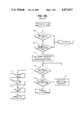
- FIG. 2a schematic illustration of the interrelationship of several maps within the automated map display system of the present invention.
- FIG. 3is a schematic illustration of the relationship between map portion images stored in frames on an optical disk and areas of the physical map from which those images were made;
- FIG. 6is a schematic illustration of a current frame table maintained by the microprocessor 107 of FIG. 1;
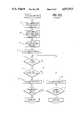
- FIGS. 7(A), 7(B), and 7(C)comprise a flow diagram for explaining the operation of the automated map system of the present invention.
- FIG. 1is a schematic block diagram of a map display system for electronically accessing and displaying images generated from physical maps.
- the map display systemincludes an image storing means for storing images of the physical maps wherein each of the map images has corresponding geographic field of view data representing the geographic coverage in longitude and latitude available as a displayed video image derived after generating the map image from the corresponding physical map, a longitude value representing a reference longitude displayed on the map image, and a latitude value representing a reference latitude displayed on the map image.
- the image storing meanscomprises an optical storage unit, such as a laser disk unit or other device for storing and retrieving optical images wherein the optical images are stored as frames of map images at associated address locations.
- the map display systemfurther includes means for displaying the map images.
- the displaying meansincludes a display 103, such as a cathode ray tube display having a selectively positionable locator.
- the map display system of the present inventionfurther includes means for selecting the latitude, longitude, and field of view of a map image to be displayed.
- the selecting meanscomprises an input device 105 such as a keyboard including keys and other means (such as a "mouse") for positioning a locator displayed on the display 103.
- the selectingmay also be accomplished by a system request generated by an application program being executed by a processor.
- a map portionincluding a point identified by the locator and having an associated reference latitude and longitude, is displayed on the screen of the display 103, it is possible to calculate the latitude and longitude of the locator on the display device 103 which corresponds to the pixel location of the locator using, among others methods described in Snyder, Map Projections Used By The U.S. Geological Survey, Geological Survey Bulletin 1532, 2d. ed. (1983).
- manipulation of the locator and the control keys of the input device 105enable the selection of a map portion image having the desired latitude and longitude included within a map image of a physical map where the map portion image is adjacent to the map portion image being displayed on the display 103 as well as the selection of a map portion image that includes a desired latitude and longitude and has a specified field of view that is either larger or smaller than the field of view of the map portion image presently displayed on the display 103.
- the Synder publicationdescribes a series of methods for determining a Cartesian ⁇ x,y ⁇ value for a given latitude/longitude on a physical map of a given projection, scale, etc.
- the methods that are describedallow transformation from a latitude/longitude position to a reference ⁇ x,y ⁇ on the physical map, or from a physical map position back to latitude/longitude.
- the algorithms for determining the latitude/longitude (on a display screen) for a pointmay use the Snyder algorithms as follows. Given that the center latitude/longitude of a displayed frame is known or can be calculated, the Snyder algorithms can determine the center of the displayed frame in Cartesian inches. Moreover, given the pixel offsets from the screen center for the point in question, the Cartesian coordinates for the center of the displayed image (derived above), information about the field-of-view (in inches), and the specifications of the display device (number of pixels across and down, for example), it is possible to calculate the Cartesian coordinates (in map-inches) for the point in question. Also, given the Cartesian (map-inches) coordinates for the point, the Snyder algorithms can be used (in reverse) to determine the latitude/longitudinal of the point.
- the map display system of the present inventionalso includes means for accessing from the storing means and for transferring to the display means the stored map image that includes the selected latitude and longitude and has corresponding field of view closest to a selected field of view.
- the accessing meansincludes a programmed processor 107 connected to the optical disk 101, the display 103, the input device 105, and an optional printer 109.
- the processor 107determines from the display 103 the current position of the locator on the display in terms of pixel values and translates the position of the locator to a corresponding latitude and longitude position.
- the processor 107receives the control information from the input device 105 and determines which map portion image is to be selected and displayed on the display 103.
- the processor 107accesses the optical disk 101 to retrieve the frame that contains the selected map image and transfers the map image to the display 103.
- the printer 109is preferably of a type that is capable of generating a hard copy of the map portion image displayed on the display 103 as well as printing out control information entered through the input device 105.
- FIG. 2is a schematic illustration of the interrelationship of three different map images corresponding to physical maps.
- Map image block 1 (MI 1 ) and map image block 2 (MI 2 )are interrelated in that they are blocks of images generated from the same physical map and, thus, include the same geographical area, but at different fields of view.
- Map image block 1is stored as a single map portion image MI 1 ,1 and, therefore, is stored as a single frame in the optical disk unit 101.
- Map image block 2is generated from the same physical map as map image block 1, but includes map portion images such that each has a field of view that is one third of the field of view of the map portion image MI 1 ,1.
- map portion image block MI 2consists of map portion images with the smallest field-of-view available for the map, it is described as the "base-level" image block.
- Each of blocks MI 1 and MI 2is represented in the map family file data records (see FIG. 5) by a block data record containing the reference longitude and latitude (LogR1/LatR1 for block MI 1 and LogR2/LatR2 for block MI 2 .)
- map portion image MI 1 in angular degreesare ⁇ log° by ⁇ lat°.
- map block 2are similarly ⁇ log° by ⁇ lat°, but since the displayed ge width is one third the displayed geographic width for map image 1, each map portion image for map image 2 has a dimension in degrees of ⁇ log/3° by ⁇ lat/3°.
- adjacent map portion images of map 2, e.g., MI 2 ,7 and MI 2 ,8,do not provide for overlap in the portions of the physical map illustrated by the map portion images.
- the automated map display system of the present inventioncan accommodate varying degrees of overlap among adjacent map portion images so that upon changing the display from one map portion image to an adjacent map portion image the position of the locator on a display 103 remains constant in terms of a specific latitude and longitude common to the overlapping map portion images, but shifts to a different pixel location of the screen on the display 103.
- map image 1 and map image 2were generated from the same physical map.
- One example of the operation of the automated map display system of the present inventioncan be shown by assuming that initially map portion image MI 1 ,1 depicting the entire map image 1 is displayed on the display 103.
- the operatormanipulates the appropriate keys on the input device 105 to place the locator at a location on the screen, e.g., a landmark(*), depicted in the map portion image MI 1 ,1.
- the processor 107determines the latitude and longitude of the landmark from the pixel location of the locator within the matrix of the screen of the display 103 and from the reference point, LogR1, LatR1, of the map portion image MI 1 ,1 using cartographic projection methodologies described herein.
- an appropriate keyis selected on the input device 105 to request that a map portion image that includes the specified location (in terms of latitude and longitude) be displayed at the next smaller field of view.
- the processor 107interprets the request to identify which of the map portion images, MI 2 ,1 -MI 2 ,7, of the map image 2 includes the designated latitude and longitude and retrieves the frame storing the appropriate map portion image from the optical disk 101 and displays the frame on the display 103.
- the processor 107will access the frame in the optical disk 101 storing the map portion image MI 2 ,5 and control the display 103 to display that map portion image and to move the locator to the designated latitude and longitude on that map portion image. If the operator wishes to examine the image of the adjacent map portion image directly south of the map portion image MI 2 ,5, the operator merely indicates through the input device 105 that he desires the display of the map portion image directly south of the map portion image presently displayed, and the map portion image MI 2 ,2 will be retrieved and displayed.
- the processor 107computes the reference latitude and longitude for the map portion image corresponding to the request. In the case of map image 2 shown in FIG. 2, there is no stored map portion image adjacently north of the map portion image MI 2 ,5. The processor 107 then automatically selects a map portion image having a field of view closest to the field of view of the map portion images of map image 2 which, in the example of FIG. 2, corresponds to the map portion image MI 1 comprising map image 1. This method provides the most suitable map portion image of all those available.
- the shaded region of map portion image MI 1includes the requested latitude and longitude and, therefore, the map portion image MIl will be retrieved from the optical disk unit 101 and displayed on the display 103.
- map portion image MI 2 ,6is displayed on the display 103 and the operator enters through the input device 105 a request or the processor 107 generates a system request to display the map portion image immediately adjacent in the northeast direction, it is clear from FIG. 2 that such map portion image is not present in either map image 2 or map image 1.
- Map image 3 of FIG. 2includes the map portion image MI 3 ,1 that includes the area immediately adjacent in the northeast direction to the map portion image MI 2 ,6.
- the map portion images MI 3 ,1 -MI 3 ,4 comprising map image 3are generated from a physical map different than the physical map used to generate the map portion images corresponding to map images 1 and 2 and has a field of view different from the fields of view of each of map image 1 and map image 2. Nonetheless, the automated map display system of the present invention determines the longitude and latitude of the map portion image adjacent in the northeast direction with respect to the map portion image MI 2 ,6 of map image 2 and selects the map portion image with a field of view closest to the displayed field of view of the operator request or the system request. As a consequence, the map portion image MI 3 ,1 of map 3 will be displayed.
- This unique feature of the present inventionallows the user to "fall off the edge of a map" without getting lost and without having to manually select a new map to view.
- the current inventionis able to select and display the best map image automatically.
- FIG. 3is a schematic illustration demonstrating the relationship between a physical map and the corresponding map portion images as stored on the optical disk 101.
- the physical mapis used to generate a plurality of blocks of map portion images wherein each map portion image is stored in a corresponding, addressable frame of the optical disk 101.
- the latitude and longitude of reference points of the physical mapmust be known.
- the latitude and longtitude of each of the map image block reference points CRF 1 ,1, CRF 2 ,1, CRF 3 ,1, and CRF 4 ,1are known.
- each frame in block 1i.e., F 1 ,i
- F 2 ,ihas a field of view in map inches which is twice the field of view in map inches of the frames in block 2, i.e., F 2 ,i, and six times the field of view in map inches of the frames included in block 3, i.e., F 3 ,i.
- FIG. 3does not illustrate any overlap between adjacent frames. It is contemplated, however, that in most cases there would be overlap in the direction of both latitude and longitude and that the overlap would be measured in constant degrees.
- a reference framewithin a block of frames there is a reference frame.
- the reference frameis F 1 ,1 and the latitude and longitude of the center of the reference frame, CRF 1 ,1, is precisely known.
- Two additional dimensionsare known for each block of frames including, with respect to block 1, ⁇ log 1 , which is the distance in longitude between the centers of adjacent frames, for example, the frames F 1 ,1 and F 1 ,2.
- ⁇ log 1is the distance in longitude between the centers of adjacent frames, for example, the frames F 1 ,1 and F 1 ,2.
- the difference in latitude, ⁇ lat 1between the centers of adjacent frames, for example, the frames F 1 ,1 and F 1 ,4, is known.
- the latitude and longitude of the reference frame CRF 1 ,1the frame-to-frame increment in longitude ⁇ log I , and the frame-to-frame difference in latitude ⁇ lat I , then the latitude and longitude of any point within a map portion image that is stored and displayed as a frame included in a block of frames can be precisely determined by the processor 107.
- the map imagesare stored in corresponding frames on the optical disk storage unit 101.
- Each of the frameshas associated therewith a corresponding frame address that enables direct addressing and accessing of the frames included on the optical disk.
- FIG. 4is a schematic illustration of a map portion index file including data relating to the field of view of the map images having corresponding map portion images stored in frames of the optical disk storage unit 101.
- the map portion index file 400includes map index data 403 through map index data 405.
- the index datamay, for example, be stored in a memory internal to the processor 107.
- Each map index data entry in the map portion index file 401pertains to a different physical map and identifies the parameters under which map portion images have been generated from the corresponding physical map.
- the map 1 index data 403includes entries identifying for physical map 1 the minimum field of view in, for example, seconds of longitude, for a block of map portion image frames generated from physical map 1, the maximum field of view in seconds of longitude for a block of map portion image frames generated from physical map 1, the maximum and minimum longitude displayed by map portion images generated from the physical map, and the minimum and maximum latitude displayed by map portion images generated from physical map 1.
- This dataenables a determination to be made whether or not a map portion image frame is stored in the optical disk storage unit 101 that fulfills the requirements of a map portion image display request entered through the input device 105 or generated as a system request by the processor 107.
- each map index data record 403, etc.enable the selection of a specific map based on the amount of geographic coverage included in a video image.
- a map image display requestspecifies a field of view that is smaller than any entry for minimum field of view in the map index data records 403, etc. found in the map index file 400
- the processor 107will determine that there is no suitable map image stored in the optical disk storage unit 101.
- the requested field of viewcorresponds to a value that is between the minimum and maximum field of view values for the map index data record 403
- the requested longitudecorresponds to a value between the minimum and maximum longitude entries for data record 403
- the requested latitudecorresponds to a value between the minimum and maximum latitude values for data record 403
- the processorwill determine that a map image included in the stored map 1 satisfies the map image display request.
- Each map index data entry within the map portion index file 400corresponds to a different map data record in the map family files as schematically illustrated in FIG. 5.
- the map family file illustrated in FIG. 5is made up of map data records, each of which includes map identification data identifying the name and source of the physical map that served as a source for the map images stored as frames in the optical disk 101 and described by the entries in the map family file shown in FIG. 5.
- the projection identification dataidentifies the cartographic projection method used in the physical map, and identifies reference parameters used by the processor 107 to display the map portion images properly and to determine accurately the pixel coordinates for the marking and display of geographic data.
- Each map data record in the map family fileincludes a variable number of records with each record corresponding to a different block of frames of map images.
- the block dataidentifies the field of view utilized in photographing the physical map to generate frames of map images.
- the physical image field of view for each block of framesis expressed in units of map inches per frame.
- the block datafurther identifies the number of scans per block and the number of frames per scan.
- the frames F 2 ,1, F 2 ,2, F 2 ,3 and F 2 ,4comprise a single scan of the block. Accordingly, block 2 includes three scans with four frames being included in each scan.
- the block datafurther includes the latitude and longitude of the reference point in the reference frame, i.e., CRF 1 ,1 for block 1 of FIG. 3.
- the frame-to-frame increment in longitude, ⁇ log° i , and the frame-to-frame increment in latitude, ⁇ lat° iare also stored as block data.
- each block data recordincludes an optical disk address that corresponds to the frame number in the optical disk storage unit 101 of the reference frame for the corresponding block.
- the map image associated with the reference frame CRF 1 ,1 of block 1is stored at the disk address indicated as the disk address data for block 1 shown in FIG. 5.
- the map images corresponding to the remaining frames of block 1(FIG. 3), i.e., F 1 ,2 .
- processor 107computes the actual frame address within the optical disk storage unit for a selected frame storing a requested map portion image by determining the relative position of the map image within the sequence of frames included in the block.
- the data stored as block data for each block of framesenables the microcomputer 107 to calculate the field of view of a map portion image within a block, determine the range of latitude and longitude covered by each map image, and access a frame in the optical disk storage unit 101 storing a desired map portion image.
- FIG. 6is a schematic illustration of a current frame table maintained by the processor 107, for example, in its internal memory.
- the current frame tablestores information that is derived from the block data associated with the map portion image currently being displayed as well as other necessary data.
- the complete map family file for that map and all its blocksare placed into memory of the processor 107.
- a blockis selected from the set of blocks, a scan is selected from that block, and a frame from that scan.
- the offset into the optical disk frame set corresponding to the pertinent blockis calculated, and the map portion image stored in the frame is then displayed.
- the current frame tableneed only contain the map identifier, block number and the scan/frame identifier. All other values that might be needed by any calculations or map portion display requests can be derived by use of the current frame table data and the data in the map family file.
- An advantage of this methodis that, since most map portion image change requests can be satisfied within the current map family file the response time is faster, and, information about previously displayed frames, or special frames (for example, home map or reference map) may be stored efficiently.
- FIGS. 7(A), 7(B), and 7(C)comprise an operational flow diagram illustrating the operation of the automated map display system of the present invention.
- the complete operationmay be described in terms of three processes, and, dependent upon the request type made by the operator or by an applications program, these processes may be combined in several different fashions. It will be apparent to those skilled in the art that many combinations of the following example processes and/or their individual steps are possible and may be implemented as required without departing from the scope of the invention, and it is intended that the present invention cover the modifications and variations of these processes provided that they come within the scope of the appended claims and their equivalents.
- Map image change requestsare made up of information specifying direction of apparent movement (where is the new image relative to the current image) and position information (latitude/longitude of the locator on the current display or latitude/longitude of the point of interest.)
- new informationmay be derived about the field of view desired and about the desired latitude/longitude coverage.
- a map request for "MAP-UP"is a request for the display of the base-level image showing the current locator position and three (or more) times the field of view shown by the current map image. Given that the current field of view might be 1.5° longitude, it may be derived that only images with a field of view of at least 4.5° longitude would be acceptable.
- the requestcould be satisfied by an image with the same field of view, encompassing a point of latitude and longitude calculated by incrementing or decrementing, as the case may be, either or both the latitude and longitude of the locator.
- the first step (A.1)is to initialize and test the hardware, and to check for file and system integrity.
- Various routinesmay be included in the initialization step (due to system differences or specific hardware requirements) including self-tests by the processor and other devices.
- step A.2is executed, in which the processor 107 selects from the optical disk 101 a default map image (either one that has been set by the user or one selected by the system), the corresponding map data set is retrieved and placed into processor memory, and the current frame table (FIG. 6) is loaded with the proper values for the current map, current block, current scan, and current frame.
- a default map imageeither one that has been set by the user or one selected by the system
- the corresponding map data setis retrieved and placed into processor memory
- the current frame table(FIG. 6) is loaded with the proper values for the current map, current block, current scan, and current frame.
- the default map portion imageprovides a reference map portion image in terms of latitude, longitude and field of view which will enable the selection of any new image having: (1), a field of view larger, smaller or equal to the currently displayed image and (2) a field of view encompassing a geographic area that is laterally adjacent to the current image, which encompasses the currently displayed area, or which is a subset of the currently displayed area.
- step A.3the optical disk track number is calculated and the optical disk is instructed to display that frame.
- the frame containing the appropriate map imagewill be retrieved from the optical disk 101 and transferred to the display device 103 under the control of the processor 107.
- the map image to be displayedwill be retrieved in response to an operator request or an application systems request.
- the optical disk address ⁇ A ⁇ of the frame to be displayedmay be calculated as:
- ⁇ Ra ⁇is the optical disk address of the reference frame for the current block
- ⁇ Sc ⁇is the current scan within the block
- ⁇ FrS ⁇is the number of frames per scan
- ⁇ Fr ⁇is the frame number within the scan.
- the request for a different map imagemay take the form of one of several possibilities.
- the requestcould be for the display of a map image that includes a latitude and longitude encompassed by the currently displayed map image and that includes either a larger or a smaller field of view.
- the requestcould also be for a map image located adjacently to the north, south, east, or west, or diagonally adjacent to the currently displayed map image.
- the requestmight be for the display of an image encompassing more than one point of specified latitude/longitude.
- steps A.5 and A.6the request parameters are tested and verified for correctness, and control is passed to the next step in the process. Under special circumstances, it may be possible to skip some of the steps shown in FIGS. 7(A), 7(B) and 7(C), however, for the purposes of this description it will be assumed that no special circumstances exist, and that all appropriate steps must be carried out.
- step A.7control is passed to the process described in 7(B).
- This processtests the current map family data set (FIG. 5) in order to determine whether the request may be satisfied within the current map. If it is possible to satisfy the map image change request within the current map data set, then control returns to step A.3, and the new map image is displayed. If it is not possible to satisfy the request within the current map data set, then additional map data sets must be examined, and step A.8 is executed, in which control is given to the process described in 7(C).
- step A.8If the process called from step A.8 is able to satisfy the map request, then the new block, scan, and frame information are loaded into the current frame table, and control passes to step A.3, where the new image is displayed and the next map request is awaited. If the process called from step A.8 is not able to satisfy the parameters of the map request, then the original map data set and original current frame table are re-loaded into memory, and control passes to step A.3, where the next map image change request is awaited.
- Step B.1a test is made to see whether the requested field of view is available within the current map set. If not, control is returned to step A.7, which then passes control to process 7(C). If the requested field of view is available, then the requested latitude and longitude are tested against the current map data set (step B.2). If the latitude/longitude requested are not available on the current map, then control is returned to step A.7, which in turn passes control to process 7(C). Otherwise control passes to step B.3.
- a range of blocksis selected from the map data set which is currently in processor memory, this range representing the best choices among the blocks available for satisfying the field of view requested. For example, if a request was made to display an image laterally adjacent to the current image with a field of view equal to the current image, then the range of block representing images with equal fields of view would be chosen for testing. As another example, if the request was for the display of an image having a field of view greater than the current field of view, then only blocks representing images which satisfied that criteria would be chosen for testing.
- step B.4the selected range of blocks is tested to determine whether the requested latitude and longitude are available within the geographic limits of the range. If the requested latitude/longitude is available, then the most suitable block is selected (step B.7). The block is selected by comparing the requested latitude/longitude with the calculated limits of each block in the range, until a block encompassing the latitude/longitude requested is found.
- step B.8the most suitable scan ( ⁇ S ⁇ ) within that block can be calculated as follows:
- ⁇ DLat ⁇is the desired latitude
- ⁇ RLat ⁇is the latitude of the reference point for the block
- ⁇ ILat ⁇is the scan-to-scan increment of latitude.
- step B.9the most suitable frame ( ⁇ F ⁇ ) within the scan may be calculated in a similar manner:
- ⁇ DLng ⁇is the desired longitude
- ⁇ RLng ⁇is the longitude of the reference point for the scan
- ⁇ ILng ⁇is the frame-to-frame increment of longitude.
- step B.9control is returned to step A.7, which loads the current frame table with the new values for block, scan and frame, and returns to step A.3 to display the map image and await the next command.
- index recordshold data concerning the set of map images generated from an individual map.
- These index recordswill be sorted, preferably in ascending order, based on the priority of several sort keys. The highest priority key is be the minimum field of view available among the images, the next highest is the maximum field of view available, followed, in decreasing priority by maximum longitude, minimum latitude, minimum longitude and maximum latitude.
- Step C.1will save the current frame table and the current map data set identification, in case the request cannot be met with any map image available, and the current map image needs to be restored.
- Step C.2sets the search entry position into the width index table based on the type of map change request.
- All map change requestsspecify an amount of geographic coverage in some manner; for example, an absolute amount of geographic area that must be displayed ("BOX”, etc.), an amount that is some factor of the currently displayed area ("MAP-UP”, “MAP-DOWN”, etc.) or an amount that is specific, but undetermined and unrelated to the current display width ("DETAIL”, "REFERENCE”, etc.)
- the search of the indexis positioned at the most advantageous point, and therefore the map image change request may be fulfilled without resorting to inefficient search methods.
- step C.4the previously calculated first index record is accessed and control is passed to steps C.5, and C.6.
- Step C.5determines whether the requested field of view can be satisfied within the display width limits indicated by the index entry, i.e., if the requested field of view is less than the minimum field of view as indicated in the index entry, or the requested field of view is greater than the maximum field of view indicated in the index entry, then the map data set represented by the index entry will not have an image which would fulfill the request, and control is passed to step C.8.
- step C.6determines whether the requested Lat/Long is encompassed by the boundaries shown in the width index record.
- the requested latitudeis compared against the minimum latitude and maximum latitude fields in the index entry under consideration, and the requested longitude is compared to the minimum longitude and maximum longitude fields in the index. If the requested latitude and longitude are shown by these tests to be encompassed by the map represented by this index, then control passes to step C.7, otherwise control passed to step C.8.
- Step C.7will then call upon the process described in FIG. 7(B) to perform testing of the actual map block data, and to select an appropriate block, scan and frame for the new map image (this process (Process B) is exactly as described above, except that any return from the process will be made to the current process--FIG. 7(C)--and not to the processing of FIG. 7(A).)
- Step C.8checks to determine whether another appropriate index record is available. If so, it is made accessable (step C.9) and control is passed to step C.5, where the index testing loop is continued. If no further index records are available, then return is made to the calling process (FIG. 7(A)), where the prior map data set and prior current frame table are restored and control is passed to step A.4 to await the next request.
Landscapes
- Engineering & Computer Science (AREA)
- Physics & Mathematics (AREA)
- Theoretical Computer Science (AREA)
- Mathematical Physics (AREA)
- Business, Economics & Management (AREA)
- Educational Administration (AREA)
- Educational Technology (AREA)
- General Physics & Mathematics (AREA)
- Processing Or Creating Images (AREA)
- Instructional Devices (AREA)
Abstract
Description
A=Ra+((SC-1)*FrS)+(Fr-1)
S=1+((DLat-RLat)/ILat
F=1+((RLng-DLng)/ILng
Claims (13)
Priority Applications (1)
| Application Number | Priority Date | Filing Date | Title |
|---|---|---|---|
| US07/089,450US4873513A (en) | 1987-08-26 | 1987-08-26 | Automated map display system |
Applications Claiming Priority (1)
| Application Number | Priority Date | Filing Date | Title |
|---|---|---|---|
| US07/089,450US4873513A (en) | 1987-08-26 | 1987-08-26 | Automated map display system |
Publications (1)
| Publication Number | Publication Date |
|---|---|
| US4873513Atrue US4873513A (en) | 1989-10-10 |
Family
ID=22217712
Family Applications (1)
| Application Number | Title | Priority Date | Filing Date |
|---|---|---|---|
| US07/089,450Expired - LifetimeUS4873513A (en) | 1987-08-26 | 1987-08-26 | Automated map display system |
Country Status (1)
| Country | Link |
|---|---|
| US (1) | US4873513A (en) |
Cited By (68)
| Publication number | Priority date | Publication date | Assignee | Title |
|---|---|---|---|---|
| WO1990014627A1 (en)* | 1989-05-15 | 1990-11-29 | Bennett Mark J | Method for generating maps |
| US5010500A (en)* | 1989-01-26 | 1991-04-23 | Xerox Corporation | Gesture-modified diagram for retrieval of image resembling diagram, with parts selectable for further interactive retrieval |
| US5036471A (en)* | 1989-04-18 | 1991-07-30 | Sanyo Electric Co., Ltd. | Apparatus for road path searching applicable to car navigation system and operation method thereof |
| US5237323A (en)* | 1990-11-21 | 1993-08-17 | Hitachi, Ltd. | Map retrieving system having a learning function |
| US5359729A (en)* | 1991-05-31 | 1994-10-25 | Timeline, Inc. | Method for searching for a given point in regions defined by attribute ranges, then sorted by lower and upper range values and dimension |
| US5396254A (en)* | 1990-11-08 | 1995-03-07 | Sanden Corporation | Position recognition system and position-coordinate converting device |
| US5544052A (en)* | 1991-04-19 | 1996-08-06 | Hitachi, Ltd. | Digital cartographic system for geographical information processing |
| US5546572A (en)* | 1991-08-28 | 1996-08-13 | Hitachi, Ltd. | Method for retrieving database of image information |
| US5594650A (en)* | 1992-10-16 | 1997-01-14 | Mobile Information Systems, Inc. | Method and apparatus for tracking vehicle location |
| US5790975A (en)* | 1989-12-13 | 1998-08-04 | Pioneer Electronic Corporation | Onboard navigational system |
| WO1998037505A3 (en)* | 1997-02-20 | 1998-11-26 | Etak Inc | Caching for pathfinding computation |
| US5884216A (en)* | 1992-10-16 | 1999-03-16 | Mobile Information System, Inc. | Method and apparatus for tracking vehicle location |
| US5904727A (en)* | 1995-05-17 | 1999-05-18 | Mobile Information Systems, Inc. | Graphical fleet management methods |
| US5922040A (en)* | 1995-05-17 | 1999-07-13 | Mobile Information System, Inc. | Method and apparatus for fleet management |
| US6125367A (en)* | 1996-10-23 | 2000-09-26 | Samsung Electronics Co., Ltd. | Map data base management method and system therefor |
| US6208353B1 (en) | 1997-09-05 | 2001-03-27 | ECOLE POLYTECHNIQUE FEDéRALE DE LAUSANNE | Automated cartographic annotation of digital images |
| US6208933B1 (en) | 1998-12-04 | 2001-03-27 | Northrop Grumman Corporation | Cartographic overlay on sensor video |
| US6263343B1 (en)* | 1996-01-11 | 2001-07-17 | Sony Corporation | System for providing and linking regularity updated map data with data related to the map |
| US6330453B1 (en)* | 1998-02-06 | 2001-12-11 | Matsushitas Electric Industrial Co., Ltd. | Map information providing method and system and terminal device used therein |
| US20020039203A1 (en)* | 2000-09-29 | 2002-04-04 | Casio Computer Co., Ltd. | Picked-up image managing device capable of managing picked-up images by grouping the same, method of determining group name, and computer usable medium storing group name determining program |
| US6404431B1 (en) | 1998-04-13 | 2002-06-11 | Northrop Grumman Corporation | Virtual map store/cartographic processor |
| US6408307B1 (en) | 1995-01-11 | 2002-06-18 | Civix-Ddi, Llc | System and methods for remotely accessing a selected group of items of interest from a database |
| US6445912B1 (en) | 1999-06-23 | 2002-09-03 | At&T Wireless Services, Inc. | System and method for checking service availability |
| US20020124004A1 (en)* | 1989-10-26 | 2002-09-05 | Michael Reed | Multimedia search system |
| US6457129B2 (en)* | 1998-03-31 | 2002-09-24 | Intel Corporation | Geographic location receiver based computer system security |
| US20020198736A1 (en)* | 2001-06-01 | 2002-12-26 | Craig Harrison | Identification, storage and display of land data on a website |
| US20030009458A1 (en)* | 1998-05-28 | 2003-01-09 | Increment P Corporation | Map information Providing system and map information searching method |
| US20030034936A1 (en)* | 2001-08-10 | 2003-02-20 | Ernst Rudolf O. | Image display system |
| US20030046451A1 (en)* | 1997-03-07 | 2003-03-06 | Mobile Information System, Inc. | System and method for mobile data processing and transmission |
| US20030063127A1 (en)* | 2001-09-13 | 2003-04-03 | Ernst Rudolf O. | High resolution display of large electronically stored or communicated images with real time roaming |
| US6570975B2 (en) | 1993-02-22 | 2003-05-27 | Murex Securities, Ltd. | Automated telecommunications call processing method |
| US6643656B2 (en) | 1991-07-31 | 2003-11-04 | Richard Esty Peterson | Computerized information retrieval system |
| US20030220734A1 (en)* | 2002-02-11 | 2003-11-27 | Harrison Craig D. | Land software tool |
| US6661884B2 (en) | 1996-06-10 | 2003-12-09 | Murex Securities, Ltd, | One number, intelligent call processing system |
| US20050116966A1 (en)* | 2002-04-04 | 2005-06-02 | Graham James J. | Web imaging serving technology |
| US6912695B2 (en) | 2001-09-13 | 2005-06-28 | Pixia Corp. | Data storage and retrieval system and method |
| US20050182560A1 (en)* | 2002-06-17 | 2005-08-18 | Elmar Cochlovius | Ergonomic map information system |
| US20050288854A1 (en)* | 2004-06-24 | 2005-12-29 | Kyocera Corporation | Mobile communication terminal and map display system |
| US20060197763A1 (en)* | 2002-02-11 | 2006-09-07 | Landnet Corporation | Document geospatial shape tagging, searching, archiving, and retrieval software |
| US7197704B1 (en)* | 1999-07-14 | 2007-03-27 | Canon Kabushiki Kaisha | Document management method, system, and storage medium thereof with priority assignment indicative of processing order |
| US20070208683A1 (en)* | 2006-02-01 | 2007-09-06 | Tele Atlas North America, Inc. | Method for differentiating duplicate or similarly named disjoint localities within a state or other principal geographic unit of interest |
| US20070226004A1 (en)* | 2001-06-01 | 2007-09-27 | Landnet Corporation | Identification, storage and display of land data on a website |
| US20080051994A1 (en)* | 2006-08-28 | 2008-02-28 | Microsoft Corporation | Representation and display of geographical popularity data |
| US20080079723A1 (en)* | 2006-05-16 | 2008-04-03 | David Hanson | System and method for visualizing multiple-sensor subsurface imaging data |
| US20090024326A1 (en)* | 2000-06-14 | 2009-01-22 | Gary Neal Young | Utility mapping and data distribution system and method |
| US20090055093A1 (en)* | 2007-08-23 | 2009-02-26 | International Business Machines Corporation | Pictorial navigation method, system, and program product |
| US20090089319A1 (en)* | 2007-10-01 | 2009-04-02 | Tele Atlas North America, Inc. | System and Method for Differentiating Duplicate Addresses in a Locality |
| US20100073371A1 (en)* | 2008-09-25 | 2010-03-25 | Pixia Corp. | Large format video archival, storage, and retrieval system and method |
| US7689621B1 (en)* | 2000-11-06 | 2010-03-30 | Navteq North America, Llc | Multi-dimensional spatial index for a geographic database |
| US7693042B1 (en) | 1999-06-23 | 2010-04-06 | At&T Mobility Ii Llc | Intelligent presentation network management system |
| US20100169012A1 (en)* | 2008-12-25 | 2010-07-01 | Sony Corporation | Map data display control apparatus, map data display control method, and program for the same |
| US20100259438A1 (en)* | 2006-05-16 | 2010-10-14 | Ross Peter Jones | Sensor cart positioning system and method |
| US20110229040A1 (en)* | 2010-03-16 | 2011-09-22 | Pixia Corp. | Method and system for converting an image |
| US20120218150A1 (en)* | 2009-10-30 | 2012-08-30 | Ntt Docomo, Inc. | Management server, population information calculation management server, non-populated area management method, and population information calculation method |
| CN101742395B (en)* | 2008-11-21 | 2012-12-05 | 厦门雅迅网络股份有限公司 | Method for downloading and displaying map data by mobile phone |
| US8532383B1 (en) | 2010-09-16 | 2013-09-10 | Pixia Corp. | Method of processing a viewport within large format imagery |
| CN103885767A (en)* | 2012-12-20 | 2014-06-25 | 国际商业机器公司 | System and method used for geographical area correlated websites |
| CN104951466A (en)* | 2014-03-28 | 2015-09-30 | 高德软件有限公司 | POI information search method, device and system and related equipment |
| US9348020B2 (en) | 2012-03-12 | 2016-05-24 | Vermeer Manufacturing Company | Offset frequency homodyne ground penetrating radar |
| US9407876B1 (en) | 2010-09-14 | 2016-08-02 | Pixia Corp. | Method and system for encoding and decoding multiple wide-area surveillance area-of-interest video codestreams |
| US9739133B2 (en) | 2013-03-15 | 2017-08-22 | Vermeer Corporation | Imaging underground objects using spatial sampling customization |
| US9813855B2 (en) | 2015-04-23 | 2017-11-07 | Blazer and Flip Flops, Inc. | Targeted venue message distribution |
| US9829339B2 (en)* | 2014-02-26 | 2017-11-28 | Blazer and Flip Flops, Inc. | Live branded dynamic mapping |
| US9906909B2 (en) | 2015-05-01 | 2018-02-27 | Blazer and Flip Flops, Inc. | Map based beacon management |
| US10129728B2 (en) | 2015-12-07 | 2018-11-13 | Blazer and Flip Flops, Inc. | Wearable device |
| US10198717B2 (en) | 2014-02-26 | 2019-02-05 | Blazer and Flip Flops, Inc. | Parental controls |
| US10210542B2 (en) | 2014-02-26 | 2019-02-19 | Blazer and Flip Flops, Inc. | Venue guest device message prioritization |
| US11526916B2 (en) | 2015-04-28 | 2022-12-13 | Blazer and Flip Flops, Inc. | Intelligent prediction of queue wait times |
Citations (5)
| Publication number | Priority date | Publication date | Assignee | Title |
|---|---|---|---|---|
| US4360876A (en)* | 1979-07-06 | 1982-11-23 | Thomson-Csf | Cartographic indicator system |
| US4513377A (en)* | 1981-06-11 | 1985-04-23 | Nippondenso Co., Ltd. | Vehicle-mounted navigator |
| US4630209A (en)* | 1981-07-01 | 1986-12-16 | Toyota Jidosha Kogyo Kabushiki Kaisha | Audio/visual display system for multiple maps |
| US4675676A (en)* | 1983-03-09 | 1987-06-23 | Nippondenso Co. Ltd. | Map display system |
| US4737916A (en)* | 1985-04-30 | 1988-04-12 | Nippondenso Co., Ltd. | Electronic map display system |
- 1987
- 1987-08-26USUS07/089,450patent/US4873513A/ennot_activeExpired - Lifetime
Patent Citations (5)
| Publication number | Priority date | Publication date | Assignee | Title |
|---|---|---|---|---|
| US4360876A (en)* | 1979-07-06 | 1982-11-23 | Thomson-Csf | Cartographic indicator system |
| US4513377A (en)* | 1981-06-11 | 1985-04-23 | Nippondenso Co., Ltd. | Vehicle-mounted navigator |
| US4630209A (en)* | 1981-07-01 | 1986-12-16 | Toyota Jidosha Kogyo Kabushiki Kaisha | Audio/visual display system for multiple maps |
| US4675676A (en)* | 1983-03-09 | 1987-06-23 | Nippondenso Co. Ltd. | Map display system |
| US4737916A (en)* | 1985-04-30 | 1988-04-12 | Nippondenso Co., Ltd. | Electronic map display system |
Cited By (158)
| Publication number | Priority date | Publication date | Assignee | Title |
|---|---|---|---|---|
| US5010500A (en)* | 1989-01-26 | 1991-04-23 | Xerox Corporation | Gesture-modified diagram for retrieval of image resembling diagram, with parts selectable for further interactive retrieval |
| US5036471A (en)* | 1989-04-18 | 1991-07-30 | Sanyo Electric Co., Ltd. | Apparatus for road path searching applicable to car navigation system and operation method thereof |
| WO1990014627A1 (en)* | 1989-05-15 | 1990-11-29 | Bennett Mark J | Method for generating maps |
| US20020124004A1 (en)* | 1989-10-26 | 2002-09-05 | Michael Reed | Multimedia search system |
| US6978277B2 (en) | 1989-10-26 | 2005-12-20 | Encyclopaedia Britannica, Inc. | Multimedia search system |
| US20050251515A1 (en)* | 1989-10-26 | 2005-11-10 | Michael Reed | Multimedia search system |
| US20050262073A1 (en)* | 1989-10-26 | 2005-11-24 | Michael Reed | Multimedia search system |
| US20050262066A1 (en)* | 1989-10-26 | 2005-11-24 | Michael Reed | Multimedia search system |
| US7051018B2 (en) | 1989-10-26 | 2006-05-23 | Encyclopaedia Britannica, Inc. | Multimedia search system |
| US7664775B2 (en) | 1989-10-26 | 2010-02-16 | Encyclopaedia Britannica, Inc. | Multimedia search system |
| US20070179977A1 (en)* | 1989-10-26 | 2007-08-02 | Michael Reed | Multimedia search system |
| US7082437B2 (en) | 1989-10-26 | 2006-07-25 | Encyclopaedia Britannica, Inc. | Multimedia search system |
| US20090313301A9 (en)* | 1989-10-26 | 2009-12-17 | Michael Reed | Multimedia search system |
| US7085778B2 (en) | 1989-10-26 | 2006-08-01 | Encyclopaedia Britannica, Inc. | Multimedia search system |
| US5790975A (en)* | 1989-12-13 | 1998-08-04 | Pioneer Electronic Corporation | Onboard navigational system |
| US5396254A (en)* | 1990-11-08 | 1995-03-07 | Sanden Corporation | Position recognition system and position-coordinate converting device |
| US5237323A (en)* | 1990-11-21 | 1993-08-17 | Hitachi, Ltd. | Map retrieving system having a learning function |
| US5544052A (en)* | 1991-04-19 | 1996-08-06 | Hitachi, Ltd. | Digital cartographic system for geographical information processing |
| US5359729A (en)* | 1991-05-31 | 1994-10-25 | Timeline, Inc. | Method for searching for a given point in regions defined by attribute ranges, then sorted by lower and upper range values and dimension |
| US6643656B2 (en) | 1991-07-31 | 2003-11-04 | Richard Esty Peterson | Computerized information retrieval system |
| US5546572A (en)* | 1991-08-28 | 1996-08-13 | Hitachi, Ltd. | Method for retrieving database of image information |
| US6026345A (en)* | 1992-10-16 | 2000-02-15 | Mobile Information Systems, Inc. | Method and apparatus for tracking vehicle location |
| US5594650A (en)* | 1992-10-16 | 1997-01-14 | Mobile Information Systems, Inc. | Method and apparatus for tracking vehicle location |
| US5884216A (en)* | 1992-10-16 | 1999-03-16 | Mobile Information System, Inc. | Method and apparatus for tracking vehicle location |
| US6608892B2 (en) | 1993-02-22 | 2003-08-19 | Murex Securities, Ltd. | Automatic routing and information system for telephone services |
| US7203300B2 (en) | 1993-02-22 | 2007-04-10 | Shaffer James D | Automatic routing and information system for telephonic services |
| US6570975B2 (en) | 1993-02-22 | 2003-05-27 | Murex Securities, Ltd. | Automated telecommunications call processing method |
| US8363814B2 (en) | 1993-02-22 | 2013-01-29 | Targus Information Corporation | Automatic routing and information system for telephonic services |
| US7136474B2 (en) | 1993-02-22 | 2006-11-14 | Murex Securities, Ltd. | Automatic routing and information system for telephonic services |
| US6408307B1 (en) | 1995-01-11 | 2002-06-18 | Civix-Ddi, Llc | System and methods for remotely accessing a selected group of items of interest from a database |
| US6415291B2 (en) | 1995-01-11 | 2002-07-02 | Civix-Ddi, Llc | System and methods for remotely accessing a selected group of items of interest from a database |
| US5922040A (en)* | 1995-05-17 | 1999-07-13 | Mobile Information System, Inc. | Method and apparatus for fleet management |
| US5904727A (en)* | 1995-05-17 | 1999-05-18 | Mobile Information Systems, Inc. | Graphical fleet management methods |
| US6263343B1 (en)* | 1996-01-11 | 2001-07-17 | Sony Corporation | System for providing and linking regularity updated map data with data related to the map |
| US8085924B2 (en) | 1996-06-10 | 2011-12-27 | Targus Information Corporation | One number, intelligent call processing system |
| US6661884B2 (en) | 1996-06-10 | 2003-12-09 | Murex Securities, Ltd, | One number, intelligent call processing system |
| US7167553B2 (en) | 1996-06-10 | 2007-01-23 | Shaffer James D | One number, intelligent call processing system |
| US6125367A (en)* | 1996-10-23 | 2000-09-26 | Samsung Electronics Co., Ltd. | Map data base management method and system therefor |
| WO1998037505A3 (en)* | 1997-02-20 | 1998-11-26 | Etak Inc | Caching for pathfinding computation |
| US5978730A (en)* | 1997-02-20 | 1999-11-02 | Sony Corporation | Caching for pathfinding computation |
| US6377887B1 (en) | 1997-02-20 | 2002-04-23 | Tele Atlas North America | Caching for pathfinding computation |
| US6889139B2 (en) | 1997-03-07 | 2005-05-03 | Sidewinder Holdings Ltd. | System and method for mobile data processing and transmission |
| US20030046451A1 (en)* | 1997-03-07 | 2003-03-06 | Mobile Information System, Inc. | System and method for mobile data processing and transmission |
| US6208353B1 (en) | 1997-09-05 | 2001-03-27 | ECOLE POLYTECHNIQUE FEDéRALE DE LAUSANNE | Automated cartographic annotation of digital images |
| US6330453B1 (en)* | 1998-02-06 | 2001-12-11 | Matsushitas Electric Industrial Co., Ltd. | Map information providing method and system and terminal device used therein |
| US6457129B2 (en)* | 1998-03-31 | 2002-09-24 | Intel Corporation | Geographic location receiver based computer system security |
| US6404431B1 (en) | 1998-04-13 | 2002-06-11 | Northrop Grumman Corporation | Virtual map store/cartographic processor |
| US6820092B2 (en)* | 1998-05-28 | 2004-11-16 | Increment P Corporation | Map information providing system and map information searching method |
| US20030009458A1 (en)* | 1998-05-28 | 2003-01-09 | Increment P Corporation | Map information Providing system and map information searching method |
| US6208933B1 (en) | 1998-12-04 | 2001-03-27 | Northrop Grumman Corporation | Cartographic overlay on sensor video |
| US7693042B1 (en) | 1999-06-23 | 2010-04-06 | At&T Mobility Ii Llc | Intelligent presentation network management system |
| US6445912B1 (en) | 1999-06-23 | 2002-09-03 | At&T Wireless Services, Inc. | System and method for checking service availability |
| US7197704B1 (en)* | 1999-07-14 | 2007-03-27 | Canon Kabushiki Kaisha | Document management method, system, and storage medium thereof with priority assignment indicative of processing order |
| US8775083B2 (en) | 2000-06-14 | 2014-07-08 | Vermeer Manufacturing Company | Utility mapping and data distribution system and method |
| US20110213585A1 (en)* | 2000-06-14 | 2011-09-01 | Gary Neal Young | Utility Mapping and Data Distribution System and Method |
| US8280634B2 (en) | 2000-06-14 | 2012-10-02 | Underground Imaging Technologies | Utility mapping and data distribution system and method |
| US7930103B2 (en) | 2000-06-14 | 2011-04-19 | Vermeer Manufacturing Company | Utility mapping and data distribution system and method |
| US9360588B2 (en) | 2000-06-14 | 2016-06-07 | Vermeer Corporation | Utility mapping and data distribution system and method |
| US20090024326A1 (en)* | 2000-06-14 | 2009-01-22 | Gary Neal Young | Utility mapping and data distribution system and method |
| US20020039203A1 (en)* | 2000-09-29 | 2002-04-04 | Casio Computer Co., Ltd. | Picked-up image managing device capable of managing picked-up images by grouping the same, method of determining group name, and computer usable medium storing group name determining program |
| US7145695B2 (en)* | 2000-09-29 | 2006-12-05 | Casio Computer Co., Ltd. | Picked-up image managing device capable of managing picked-up images by grouping the same, method of determining group name, and computer usable medium storing group name determining program |
| US7689621B1 (en)* | 2000-11-06 | 2010-03-30 | Navteq North America, Llc | Multi-dimensional spatial index for a geographic database |
| US7171389B2 (en)* | 2001-06-01 | 2007-01-30 | Landnet Corporation | Identification, storage and display of land data on a website |
| US20070226004A1 (en)* | 2001-06-01 | 2007-09-27 | Landnet Corporation | Identification, storage and display of land data on a website |
| US20020198736A1 (en)* | 2001-06-01 | 2002-12-26 | Craig Harrison | Identification, storage and display of land data on a website |
| US7119811B2 (en)* | 2001-08-10 | 2006-10-10 | Pixia Corp. | Image display system |
| US20030034936A1 (en)* | 2001-08-10 | 2003-02-20 | Ernst Rudolf O. | Image display system |
| US7607106B2 (en) | 2001-09-13 | 2009-10-20 | Pixia Corp. | Image display system |
| US6912695B2 (en) | 2001-09-13 | 2005-06-28 | Pixia Corp. | Data storage and retrieval system and method |
| US20030063127A1 (en)* | 2001-09-13 | 2003-04-03 | Ernst Rudolf O. | High resolution display of large electronically stored or communicated images with real time roaming |
| US8341548B2 (en) | 2001-09-13 | 2012-12-25 | Pixia Corp. | Image display system |
| US20050210405A1 (en)* | 2001-09-13 | 2005-09-22 | Pixia Corp. | Image display system |
| US7840908B2 (en) | 2001-09-13 | 2010-11-23 | Pixia Corp. | High resolution display of large electronically stored or communicated images with real time roaming |
| US20100111411A1 (en)* | 2001-09-13 | 2010-05-06 | Pixia Corp. | Image display system |
| US9177525B2 (en) | 2001-09-13 | 2015-11-03 | Pixia Corp. | Image display system |
| US8984438B2 (en) | 2001-09-13 | 2015-03-17 | Pixia Corp. | Image Display System |
| US20060125828A1 (en)* | 2002-02-11 | 2006-06-15 | Landnet Corporation | Land software tool |
| US20080130955A1 (en)* | 2002-02-11 | 2008-06-05 | Landnet Corporation | Land software tool |
| US20060197763A1 (en)* | 2002-02-11 | 2006-09-07 | Landnet Corporation | Document geospatial shape tagging, searching, archiving, and retrieval software |
| US20030220734A1 (en)* | 2002-02-11 | 2003-11-27 | Harrison Craig D. | Land software tool |
| US7054741B2 (en)* | 2002-02-11 | 2006-05-30 | Landnet Corporation | Land software tool |
| US7356406B2 (en)* | 2002-02-11 | 2008-04-08 | Landnet Corporation | Land software tool |
| US7580045B2 (en) | 2002-02-11 | 2009-08-25 | Landnet Corporation | Land software tool |
| US20050116966A1 (en)* | 2002-04-04 | 2005-06-02 | Graham James J. | Web imaging serving technology |
| US7096118B2 (en)* | 2002-06-17 | 2006-08-22 | Harman Becker Automotive Systems Gmbh | Ergonomic map information system |
| US20050182560A1 (en)* | 2002-06-17 | 2005-08-18 | Elmar Cochlovius | Ergonomic map information system |
| JP2006501522A (en)* | 2002-10-03 | 2006-01-12 | ピクシア・コーポレイション | Image display system |
| US8725406B2 (en)* | 2004-06-24 | 2014-05-13 | Kyocera Corporation | Mobile communication terminal and map display system |
| US20050288854A1 (en)* | 2004-06-24 | 2005-12-29 | Kyocera Corporation | Mobile communication terminal and map display system |
| US7831382B2 (en) | 2006-02-01 | 2010-11-09 | TeleAtlas B.V. | Method for differentiating duplicate or similarly named disjoint localities within a state or other principal geographic unit of interest |
| WO2007090167A3 (en)* | 2006-02-01 | 2008-04-24 | Tele Atlas North America Inc | Method for differentiating duplicate or similarly named disjoint localities within a state |
| US20070208683A1 (en)* | 2006-02-01 | 2007-09-06 | Tele Atlas North America, Inc. | Method for differentiating duplicate or similarly named disjoint localities within a state or other principal geographic unit of interest |
| JP2009525550A (en)* | 2006-02-01 | 2009-07-09 | テレ アトラス ノース アメリカ インコーポレイテッド | How to distinguish between distant localities that have exactly the same or similar names within a state or other major geographic unit of interest |
| US8779967B2 (en) | 2006-05-16 | 2014-07-15 | Underground Imaging Technologies, Inc. | Sensor cart positioning system and method |
| US8089390B2 (en) | 2006-05-16 | 2012-01-03 | Underground Imaging Technologies, Inc. | Sensor cart positioning system and method |
| US9646415B2 (en)* | 2006-05-16 | 2017-05-09 | Underground Imaging Technologies, Inc. | System and method for visualizing multiple-sensor subsurface imaging data |
| US9470789B2 (en) | 2006-05-16 | 2016-10-18 | Underground Imaging Technologies, Inc. | Sensor cart positioning system and method |
| US20080079723A1 (en)* | 2006-05-16 | 2008-04-03 | David Hanson | System and method for visualizing multiple-sensor subsurface imaging data |
| US20100259438A1 (en)* | 2006-05-16 | 2010-10-14 | Ross Peter Jones | Sensor cart positioning system and method |
| US20080051994A1 (en)* | 2006-08-28 | 2008-02-28 | Microsoft Corporation | Representation and display of geographical popularity data |
| US20090055093A1 (en)* | 2007-08-23 | 2009-02-26 | International Business Machines Corporation | Pictorial navigation method, system, and program product |
| US20130018579A1 (en)* | 2007-08-23 | 2013-01-17 | International Business Machines Corporation | Pictorial navigation |
| US8364397B2 (en)* | 2007-08-23 | 2013-01-29 | International Business Machines Corporation | Pictorial navigation |
| US8983773B2 (en)* | 2007-08-23 | 2015-03-17 | International Business Machines Corporation | Pictorial navigation |
| US20090089319A1 (en)* | 2007-10-01 | 2009-04-02 | Tele Atlas North America, Inc. | System and Method for Differentiating Duplicate Addresses in a Locality |
| US20100073371A1 (en)* | 2008-09-25 | 2010-03-25 | Pixia Corp. | Large format video archival, storage, and retrieval system and method |
| US8644690B2 (en) | 2008-09-25 | 2014-02-04 | Pixia Corp. | Large format video archival, storage, and retrieval system |
| US8290346B2 (en) | 2008-09-25 | 2012-10-16 | Pixia Corp. | Large format video archival, storage, and retrieval system and method |
| CN101742395B (en)* | 2008-11-21 | 2012-12-05 | 厦门雅迅网络股份有限公司 | Method for downloading and displaying map data by mobile phone |
| US20100169012A1 (en)* | 2008-12-25 | 2010-07-01 | Sony Corporation | Map data display control apparatus, map data display control method, and program for the same |
| US8290706B2 (en)* | 2008-12-25 | 2012-10-16 | Sony Corporation | Map data display control apparatus, map data display control method, and program for the same |
| US20120218150A1 (en)* | 2009-10-30 | 2012-08-30 | Ntt Docomo, Inc. | Management server, population information calculation management server, non-populated area management method, and population information calculation method |
| US9684848B2 (en) | 2010-03-16 | 2017-06-20 | Pixia Corp. | System and method for retrieving an image containing image statistical data |
| US10565254B2 (en) | 2010-03-16 | 2020-02-18 | Pixia Corp. | System and method for storing points of polygons related to an image |
| US9489729B2 (en) | 2010-03-16 | 2016-11-08 | Pixia Corp. | Method and system for storing statistical data of an image |
| US8411970B2 (en) | 2010-03-16 | 2013-04-02 | Pixia Corp. | Method and system for determining statistical data for image pixels having a higher bit depth per band |
| US10311098B2 (en) | 2010-03-16 | 2019-06-04 | Pixia Corp. | System and method for storing points of polygons related to an image |
| US20110229040A1 (en)* | 2010-03-16 | 2011-09-22 | Pixia Corp. | Method and system for converting an image |
| US10681305B2 (en) | 2010-09-14 | 2020-06-09 | Pixia Corp. | Method and system for combining multiple area-of-interest video codestreams into a combined video codestream |
| US9621904B2 (en) | 2010-09-14 | 2017-04-11 | Pixia Corp. | Method and system for transmitting multiple wide-area surveillance area-of-interest video codestreams |
| US11044437B2 (en) | 2010-09-14 | 2021-06-22 | Pixia Corp. | Method and system for combining multiple area-of-interest video codestreams into a combined video codestream |
| US9407876B1 (en) | 2010-09-14 | 2016-08-02 | Pixia Corp. | Method and system for encoding and decoding multiple wide-area surveillance area-of-interest video codestreams |
| US8532383B1 (en) | 2010-09-16 | 2013-09-10 | Pixia Corp. | Method of processing a viewport within large format imagery |
| US9947072B2 (en) | 2010-09-16 | 2018-04-17 | Pixia Corp. | Method and system of managing data files |
| US9129348B2 (en) | 2010-09-16 | 2015-09-08 | Pixia Corp. | Container file for large format imagery and method of creating the container file and organizing data within the container file |
| US9218637B2 (en) | 2010-09-16 | 2015-12-22 | Pixia Corp. | Method of making a video stream from a plurality of viewports within large format imagery |
| US8755609B2 (en) | 2010-09-16 | 2014-06-17 | Pixia Corp. | Method of processing a viewport within large format imagery |
| US9129349B2 (en) | 2010-09-16 | 2015-09-08 | Pixia Corp. | Method of inserting an image into a container file |
| US9123092B2 (en) | 2010-09-16 | 2015-09-01 | Pixia Corp. | Method of creating or updating a container file for storing image files |
| US9058642B2 (en) | 2010-09-16 | 2015-06-16 | Pixia Corp. | Method of processing a viewport within large format imagery |
| US9477996B2 (en) | 2010-09-16 | 2016-10-25 | Pixia Corp. | Method and system of processing a viewport within large format imagery |
| US10970810B2 (en) | 2010-09-16 | 2021-04-06 | Pixia Corp. | Method and system of managing data files |
| US9501806B2 (en) | 2010-09-16 | 2016-11-22 | Pixia Corp. | Method of creating or updating a container file for storing image files |
| US8949913B1 (en) | 2010-09-16 | 2015-02-03 | Pixia Corp. | Method of making a video stream from a plurality of viewports within large format imagery |
| US8885940B2 (en) | 2010-09-16 | 2014-11-11 | Pixia Corp. | Method of inserting an image into a container file |
| US8532397B1 (en) | 2010-09-16 | 2013-09-10 | Pixia Corp. | Method of creating a container file for large format imagery and organizing data within the container file |
| US8768106B2 (en) | 2010-09-16 | 2014-07-01 | Pixia Corp. | Container file for large format imagery and method of creating the container file and organizing data within the container file |
| US11698923B2 (en) | 2010-09-16 | 2023-07-11 | Pixia Corp. | Method and system of managing data files |
| US10559059B2 (en) | 2010-09-16 | 2020-02-11 | Pixia Corp. | Method and system of managing data files |
| US9348020B2 (en) | 2012-03-12 | 2016-05-24 | Vermeer Manufacturing Company | Offset frequency homodyne ground penetrating radar |
| CN103885767A (en)* | 2012-12-20 | 2014-06-25 | 国际商业机器公司 | System and method used for geographical area correlated websites |
| US20140181064A1 (en)* | 2012-12-20 | 2014-06-26 | International Business Machines Corporation | Geographical area correlated websites |
| US9158852B2 (en)* | 2012-12-20 | 2015-10-13 | International Business Machines Corporation | Geographical area correlated websites |
| CN103885767B (en)* | 2012-12-20 | 2017-04-12 | 国际商业机器公司 | System and method used for geographical area correlated websites |
| US9739133B2 (en) | 2013-03-15 | 2017-08-22 | Vermeer Corporation | Imaging underground objects using spatial sampling customization |
| US9829339B2 (en)* | 2014-02-26 | 2017-11-28 | Blazer and Flip Flops, Inc. | Live branded dynamic mapping |
| US10198717B2 (en) | 2014-02-26 | 2019-02-05 | Blazer and Flip Flops, Inc. | Parental controls |
| US10210542B2 (en) | 2014-02-26 | 2019-02-19 | Blazer and Flip Flops, Inc. | Venue guest device message prioritization |
| US9909896B2 (en) | 2014-02-26 | 2018-03-06 | Blazer and Flip Flops, Inc. | Live branded dynamic mapping |
| CN104951466B (en)* | 2014-03-28 | 2019-10-22 | 高德软件有限公司 | A kind of POI information searching method, device, system and relevant device |
| CN104951466A (en)* | 2014-03-28 | 2015-09-30 | 高德软件有限公司 | POI information search method, device and system and related equipment |
| US10299070B2 (en) | 2015-04-23 | 2019-05-21 | Blazer and Flip Flops, Inc. | Targeted venue message distribution |
| US9813855B2 (en) | 2015-04-23 | 2017-11-07 | Blazer and Flip Flops, Inc. | Targeted venue message distribution |
| US10028091B2 (en) | 2015-04-23 | 2018-07-17 | Blazer and Flip Flops, Inc. | Targeted venue message distribution |
| US11526916B2 (en) | 2015-04-28 | 2022-12-13 | Blazer and Flip Flops, Inc. | Intelligent prediction of queue wait times |
| US10149103B2 (en) | 2015-05-01 | 2018-12-04 | Blazer and Flip Flops, Inc. | Map based beacon management |
| US9906909B2 (en) | 2015-05-01 | 2018-02-27 | Blazer and Flip Flops, Inc. | Map based beacon management |
| US10129728B2 (en) | 2015-12-07 | 2018-11-13 | Blazer and Flip Flops, Inc. | Wearable device |
Similar Documents
| Publication | Publication Date | Title |
|---|---|---|
| US4873513A (en) | Automated map display system | |
| JP3473398B2 (en) | Map application system and map display control method | |
| US6278939B1 (en) | Method and system for providing data from a remotely located geographic database for use in navigation system units | |
| US6292745B1 (en) | Method and system for forming a database of geographic data for distribution to navigation system units | |
| US5884219A (en) | Moving map navigation system | |
| US6199015B1 (en) | Map-based navigation system with overlays | |
| US6343301B1 (en) | Method and system for collecting data for updating a geographic database | |
| US5857199A (en) | Retrieval method using image information | |
| US6081803A (en) | Support for alternative names in a geographic database used with a navigation program and methods for use and formation thereof | |
| US6038559A (en) | Segment aggregation in a geographic database and methods for use thereof in a navigation application | |
| EP0838764B1 (en) | Map data base management method and system therefor | |
| JPH0520365A (en) | A management method for multiple drawings in a geographical information management system | |
| EP0439543A1 (en) | A method of storage and retrieval of digital map data based upon a tessellated geoid system. | |
| DE10360442A1 (en) | Map search system | |
| US5237323A (en) | Map retrieving system having a learning function | |
| US4744033A (en) | Electronic display system | |
| KR100375553B1 (en) | Geographic Information Service Method of Using Internet Network | |
| KR20000057650A (en) | Map database device | |
| AU2005284445A1 (en) | Information point | |
| JP2000011000A (en) | Retrieval device and method therefor | |
| JPH023874A (en) | Method of determining and storing important data for road network map stored in data memory | |
| Barrow | Interactive aids for cartography and photo interpretation | |
| EP0741380A2 (en) | A display method for tiled data images | |
| JP2004053889A (en) | Method and system for displaying map information | |
| JP2733285B2 (en) | Map reading device and map information storage medium |
Legal Events
| Date | Code | Title | Description |
|---|---|---|---|
| AS | Assignment | Owner name:GEODISPLAY TECHNOLOGY LIMITED PARTNERSHIP, 7315 WI Free format text:ASSIGNMENT OF ASSIGNORS INTEREST.;ASSIGNORS:SOULTS, DONALD J.;DANIELS, NEIL A.;REEL/FRAME:004789/0908 Effective date:19870825 Owner name:GEODISPLAY TECHNOLOGY LIMITED PARTNERSHIP, 7315 WI Free format text:ASSIGNMENT OF ASSIGNORS INTEREST;ASSIGNORS:SOULTS, DONALD J.;DANIELS, NEIL A.;REEL/FRAME:004789/0908 Effective date:19870825 | |
| STCF | Information on status: patent grant | Free format text:PATENTED CASE | |
| FEPP | Fee payment procedure | Free format text:PAYOR NUMBER ASSIGNED (ORIGINAL EVENT CODE: ASPN); ENTITY STATUS OF PATENT OWNER: LARGE ENTITY | |
| FPAY | Fee payment | Year of fee payment:4 | |
| FPAY | Fee payment | Year of fee payment:8 | |
| AS | Assignment | Owner name:SILICON VALLEY BANK, A CALIFORNIA BANKING CORP., C Free format text:SECURITY INTEREST;ASSIGNOR:ROADSHOW INTERNATIONAL, INC.;REEL/FRAME:008568/0239 Effective date:19970623 | |
| FEPP | Fee payment procedure | Free format text:PAT HLDR NO LONGER CLAIMS SMALL ENT STAT AS SMALL BUSINESS (ORIGINAL EVENT CODE: LSM2); ENTITY STATUS OF PATENT OWNER: LARGE ENTITY | |
| FPAY | Fee payment | Year of fee payment:12 |