US4872515A - Drill rod for percussion drilling - Google Patents
Drill rod for percussion drillingDownload PDFInfo
- Publication number
- US4872515A US4872515AUS07/108,089US10808987AUS4872515AUS 4872515 AUS4872515 AUS 4872515AUS 10808987 AUS10808987 AUS 10808987AUS 4872515 AUS4872515 AUS 4872515A
- Authority
- US
- United States
- Prior art keywords
- thread
- lining
- drill rod
- flank
- along
- Prior art date
- Legal status (The legal status is an assumption and is not a legal conclusion. Google has not performed a legal analysis and makes no representation as to the accuracy of the status listed.)
- Expired - Fee Related
Links
- 238000009527percussionMethods0.000titleclaimsabstractdescription9
- 238000005553drillingMethods0.000titleabstractdescription5
- 239000007769metal materialSubstances0.000claimsabstractdescription7
- PXHVJJICTQNCMI-UHFFFAOYSA-NNickelChemical compound[Ni]PXHVJJICTQNCMI-UHFFFAOYSA-N0.000claimsdescription6
- 229910052759nickelInorganic materials0.000claimsdescription3
- 239000010941cobaltSubstances0.000claimsdescription2
- 229910017052cobaltInorganic materials0.000claimsdescription2
- GUTLYIVDDKVIGB-UHFFFAOYSA-Ncobalt atomChemical compound[Co]GUTLYIVDDKVIGB-UHFFFAOYSA-N0.000claimsdescription2
- 239000002184metalSubstances0.000claims7
- 229910052751metalInorganic materials0.000claims7
- 230000000712assemblyEffects0.000claims3
- 238000000429assemblyMethods0.000claims3
- 239000000463materialSubstances0.000abstractdescription11
- 229910000831SteelInorganic materials0.000abstractdescription5
- 239000010959steelSubstances0.000abstractdescription5
- 230000008878couplingEffects0.000description7
- 238000010168coupling processMethods0.000description7
- 238000005859coupling reactionMethods0.000description7
- 229910000906BronzeInorganic materials0.000description3
- RYGMFSIKBFXOCR-UHFFFAOYSA-NCopperChemical compound[Cu]RYGMFSIKBFXOCR-UHFFFAOYSA-N0.000description3
- 239000010974bronzeSubstances0.000description3
- KUNSUQLRTQLHQQ-UHFFFAOYSA-Ncopper tinChemical compound[Cu].[Sn]KUNSUQLRTQLHQQ-UHFFFAOYSA-N0.000description3
- XAGFODPZIPBFFR-UHFFFAOYSA-NaluminiumChemical compound[Al]XAGFODPZIPBFFR-UHFFFAOYSA-N0.000description2
- 229910052782aluminiumInorganic materials0.000description2
- 238000000034methodMethods0.000description2
- 238000005507sprayingMethods0.000description2
- 238000007751thermal sprayingMethods0.000description2
- 230000007704transitionEffects0.000description2
- 229910000760Hardened steelInorganic materials0.000description1
- 230000015572biosynthetic processEffects0.000description1
- 238000005219brazingMethods0.000description1
- 230000001427coherent effectEffects0.000description1
- 229910052802copperInorganic materials0.000description1
- 239000010949copperSubstances0.000description1
- 238000010438heat treatmentMethods0.000description1
- 230000001050lubricating effectEffects0.000description1
- 229910000734martensiteInorganic materials0.000description1
- 230000035515penetrationEffects0.000description1
- 239000000843powderSubstances0.000description1
- 238000003466weldingMethods0.000description1
Images

Classifications
- F—MECHANICAL ENGINEERING; LIGHTING; HEATING; WEAPONS; BLASTING
- F16—ENGINEERING ELEMENTS AND UNITS; GENERAL MEASURES FOR PRODUCING AND MAINTAINING EFFECTIVE FUNCTIONING OF MACHINES OR INSTALLATIONS; THERMAL INSULATION IN GENERAL
- F16L—PIPES; JOINTS OR FITTINGS FOR PIPES; SUPPORTS FOR PIPES, CABLES OR PROTECTIVE TUBING; MEANS FOR THERMAL INSULATION IN GENERAL
- F16L15/00—Screw-threaded joints; Forms of screw-threads for such joints
- F16L15/006—Screw-threaded joints; Forms of screw-threads for such joints with straight threads
- E—FIXED CONSTRUCTIONS
- E21—EARTH OR ROCK DRILLING; MINING
- E21B—EARTH OR ROCK DRILLING; OBTAINING OIL, GAS, WATER, SOLUBLE OR MELTABLE MATERIALS OR A SLURRY OF MINERALS FROM WELLS
- E21B17/00—Drilling rods or pipes; Flexible drill strings; Kellies; Drill collars; Sucker rods; Cables; Casings; Tubings
- E21B17/02—Couplings; joints
- E21B17/04—Couplings; joints between rod or the like and bit or between rod and rod or the like
- E21B17/042—Threaded
- E21B17/0426—Threaded with a threaded cylindrical portion, e.g. for percussion rods
Definitions
- the present inventionrelates to an extension drill rod for percussion drilling machines, more specifically a drill rod consisting of a rod or a sleeve that is provided with a threaded portion for engagement with another correspondingly threaded drill rod.
- the threaded portion of the drill rodis provided with a wear lining consisting of a layer of a material softer than that of the drill rod, usually of steel, whereby the layer is metallurgically bonded to the threaded portion of the drill rod.
- a wear lining materialis a commercially available bronze material such as copper bronze or aluminum bronze.
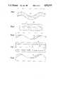
- FIG. 1is a sectional longitudinal view of a conventional threaded coupling
- FIG. 2is an enlarged longitudinal section of the threaded coupling of FIG. 1,
- FIG. 3is a partially enlarged axial section of the wear lining applied on to a drill rod in accordance with the present invention
- FIG. 4is an enlarged section of a wear lining of FIG. 3,
- FIG. 5is an axial section of a drill rod according to an alternative embodiment of the invention.
- FIG. 6is an enlarged axial section of the wear lining applied to the drill rod in FIG. 5,
- FIG. 7is a coupling sleeve provided with a wear lining according to the invention.
- FIG. 8is an enlarged section of the wear lining in FIG. 7.
- the threaded coupling that is shown in FIG. 1incorporates two externally threaded end portions of two drill rods 10 and 11 which are held together by an internally threaded coupling sleeve 12. Both the drill rods 10, 11 and the sleeve 12 are made of hardened steel.
- top portions 13 and the bottom portions 14are smoothly rounded whereas the pressure flanks located therebetween are partially straight.
- the sleeve 12is similarly provided with smoothly rounded top portions 16 and bottom portions 17, and partially straight flanks 18 therebetween.
- the threadsare only abutting each other along the flank portions 15 and 18, respectively.
- the transition areas between the flanks and the tops and bottoms of the rod 10 and the sleeve 12are smoothly rounded in order to eliminate exposure regions for fatigue cracks.
- the flank angle of the flanks 15, 18 measured in relation to the drill axisis normally in the area 25°-40° at the same time as the thread pitch amounts to 6.5°-9°.
- the threaded portion of the rods 10, 11is provided with a wear lining in the form of a layer 19 that is metallurgically bonded to the rod 10, 11.
- This wear lining 19shall be made of a metallic material that is softer than the material from which the drill rod has been manufactured. It is the intention that such layer would give a certain lubricating effect to the steel.
- suitable material for such wear liningcan be mentioned copper bronze or aluminum bronze but also other materials softer than steel could be used.
- the wear lining 19is provided as a layer continuously applied along the entire threaded portion with substantially constant layer thickness. Having regard to the fact that in such threaded couplings it is only one of the thread flanks that comes into abutment with the other tghread as shown in FIG. 2, it is also possible to apply the layer 20 to the threaded portion in a spiral pattern as shown in FIG. 4-5. In this instance layer 20 should be applied so that it covers the whole abutting flank and also an essential portion of the thread's bottom portion as shown in FIG. 6, whereas the non-abutting flanks could be entirely free from such layer.
- the wear liningcould be provided as a coherent layer along the entire threaded portion.
- a first layercould be provided along the threaded portion on top of which a second layer 19, 20 is applied.
- suitable material for said first layercould be used a nickel-based material or a cobalt-based material. The purpose of such embodiment would be to prevent copper penetration into the steel in connection with hardening.
- An intermediate layer of a nickel materialcould also be used in order to achieve an improved bonding between the outer wear lining and the drill rod.
- the wear lining 19, 20is preferably applied to the drill rod by thermal spraying of powder.
- the rodmust first be heated to a certain temperature which for hot spraying is about 300°-400° C. In connection with this spraying the temperature of the rod will increase.
- the rodis then allowed to cool off after which it is subjected to a turning operation aimed to give the desired final thread contour.
- the layeris first applied by thermal spraying after which the layer is taken away from the non-abutting flank portions of the thread.
- the wear lining 19can also be applied by other methods such as hard brazing or by MIG-, TIG - or electrode arc welding methods.
- a wear lining according to this inventioncan also be applied to a drill rod having a male thread at one of its ends and a female thread at is other end.
- Such wear liningcan also be applied to an adapter having a splinesprovided portion at one end and a threaded portion at its other end.
- the wear liningis applied to a drill rod, the threaded portion of which includes straight tops, straight bottoms and straight flanks portions therebetween where smoothly curved portions are provided as transitions between said tops, flanks and bottoms.
- the layer thickness of said wear lining 19, 20should normally be less than 4 mm. This recommended value should be selected for rods having a thread diameter in the range 32-45 mm. For coarser dimensions of such drill rods the thickness of said wear lining could be somewhat larger.
Landscapes
- Engineering & Computer Science (AREA)
- Mechanical Engineering (AREA)
- Life Sciences & Earth Sciences (AREA)
- Geology (AREA)
- Mining & Mineral Resources (AREA)
- General Engineering & Computer Science (AREA)
- Physics & Mathematics (AREA)
- Environmental & Geological Engineering (AREA)
- Fluid Mechanics (AREA)
- General Life Sciences & Earth Sciences (AREA)
- Geochemistry & Mineralogy (AREA)
- Earth Drilling (AREA)
Abstract
Description
The present invention relates to an extension drill rod for percussion drilling machines, more specifically a drill rod consisting of a rod or a sleeve that is provided with a threaded portion for engagement with another correspondingly threaded drill rod.
Various types of threaded connections for percussion drilling machines are previously known in which flank angles and pitch angles have been varied in order to optimize the threaded coupling with regard to those percussive forces subjected to the threaded connections. It is still a problem, however, that excessive rapid wear occurs because of those increased percussive forces that are used with modern drilling machines. The main reasons for rapid wear of such threaded connections are pitting damages due to local heating and formation of friction martensite.
In accordance with the present invention a new solution to this problem is proposed according to which the threaded portion of the drill rod is provided with a wear lining consisting of a layer of a material softer than that of the drill rod, usually of steel, whereby the layer is metallurgically bonded to the threaded portion of the drill rod. One suitable wear lining material is a commercially available bronze material such as copper bronze or aluminum bronze.
The invention will now be described more in detail in connection with the appending drawings in which
THE DRAWINGS
FIG. 1 is a sectional longitudinal view of a conventional threaded coupling,
FIG. 2 is an enlarged longitudinal section of the threaded coupling of FIG. 1,
FIG. 3 is a partially enlarged axial section of the wear lining applied on to a drill rod in accordance with the present invention,
FIG. 4 is an enlarged section of a wear lining of FIG. 3,
FIG. 5 is an axial section of a drill rod according to an alternative embodiment of the invention,
FIG. 6 is an enlarged axial section of the wear lining applied to the drill rod in FIG. 5,
FIG. 7 is a coupling sleeve provided with a wear lining according to the invention,
FIG. 8 is an enlarged section of the wear lining in FIG. 7.
The threaded coupling that is shown in FIG. 1 incorporates two externally threaded end portions of twodrill rods coupling sleeve 12. Both the drill rods 10, 11 and thesleeve 12 are made of hardened steel.
With the embodiment shown in FIGS. 1-2 thetop portions 13 and thebottom portions 14 are smoothly rounded whereas the pressure flanks located therebetween are partially straight. Thesleeve 12 is similarly provided with smoothly roundedtop portions 16 andbottom portions 17, and partiallystraight flanks 18 therebetween. The threads are only abutting each other along theflank portions rod 10 and thesleeve 12 are smoothly rounded in order to eliminate exposure regions for fatigue cracks. The flank angle of theflanks
In accordance with the invention the threaded portion of therods layer 19 that is metallurgically bonded to therod wear lining 19 shall be made of a metallic material that is softer than the material from which the drill rod has been manufactured. It is the intention that such layer would give a certain lubricating effect to the steel. As suitable material for such wear lining can be mentioned copper bronze or aluminum bronze but also other materials softer than steel could be used.
In accordance with one preferred embodiment of the invention thewear lining 19 is provided as a layer continuously applied along the entire threaded portion with substantially constant layer thickness. Having regard to the fact that in such threaded couplings it is only one of the thread flanks that comes into abutment with the other tghread as shown in FIG. 2, it is also possible to apply thelayer 20 to the threaded portion in a spiral pattern as shown in FIG. 4-5. In thisinstance layer 20 should be applied so that it covers the whole abutting flank and also an essential portion of the thread's bottom portion as shown in FIG. 6, whereas the non-abutting flanks could be entirely free from such layer.
In accordance with another possible embodiment of the invention, the wear lining could be provided as a coherent layer along the entire threaded portion. The thickness of which, however, could vary such that a thicker layer is provided along the abutting flank portions, whereas a thinner layer is provided along the remainder portion of the thread.
According to yet another embodiment of the invention, a first layer could be provided along the threaded portion on top of which asecond layer
Thewear lining wear lining 19 can also be applied by other methods such as hard brazing or by MIG-, TIG - or electrode arc welding methods.
In addition to drill rods threaded externally or internally at both ends, a wear lining according to this invention can also be applied to a drill rod having a male thread at one of its ends and a female thread at is other end. Such wear lining can also be applied to an adapter having a splinesprovided portion at one end and a threaded portion at its other end.
In accordance with a further embodiment of the invention the wear lining is applied to a drill rod, the threaded portion of which includes straight tops, straight bottoms and straight flanks portions therebetween where smoothly curved portions are provided as transitions between said tops, flanks and bottoms.
The layer thickness of saidwear lining
Claims (5)
1. A force-transmitting element in percussion drill rod assemblies, comprising a cylindrical metal body including an integral thread, and a lining disposed on said thread, said lining comprising a metallic material softer than said thread, said lining being metallurgically bonded to said thread, said lining extending substantially the entirety of said thread and being of greater thickness along one of the thread flanks than along a remaining thread flank.
2. A force-transmitting element in percussion drill rod assemblies, comprising a cylindrical metal body including an integral thread, and a lining disposed on said thread, said lining comprising a metallic material softer than said thread, said lining being metallurgically bonded to said thread, a nickel-based layer being interposed between said lining and said thread.
3. A force-transmitting element in percussion drill rod assemblies, comprising a cylindrical metal body including an integral thread, and a lining disposed on said thread, said lining comprising a metallic material softer than said thread, said lining being metallurgically bonded to said thread, a cobalt-based layer being interposed between said lining and said thread.
4. A percussion drill rod assembly comprising a metal rod having an external thread, and a hollow metal sleeve having an internal thread secured to said external thread, said threads being in contact along only one set of opposing thread flanks, and a lining disposed on the contacting flank of one of said threads, said lining comprising a metallic material softer than said one thread and being metallurgically bonded to said one thread, said lining extending along only the contacting flank of said one thread.
5. A percussion drill rod assembly comprising a metal rod having an external thread, and a hollow metal sleeve having an internal thread secured to said external thread, said threads being in contact along only one set of opposing thread flanks, and a lining disposed on the contacting flank of one of said threads, said lining comprising a metallic material softer than said one thread and being metallurgically bonded to said one thread, said lining extending along substantially the entirety of said one thread and being of greater thickness along the contacting flank of said one thread than along the other flank of said one thread.
Applications Claiming Priority (2)
| Application Number | Priority Date | Filing Date | Title |
|---|---|---|---|
| SE8604373ASE460301B (en) | 1986-10-15 | 1986-10-15 | CUTTING ROD FOR STOCKING DRILLING MACHINE |
| SE8604373 | 1986-10-15 |
Related Child Applications (1)
| Application Number | Title | Priority Date | Filing Date |
|---|---|---|---|
| US07/384,658ContinuationUS5064004A (en) | 1986-10-15 | 1989-07-25 | Drill rod for percussion drilling |
Publications (1)
| Publication Number | Publication Date |
|---|---|
| US4872515Atrue US4872515A (en) | 1989-10-10 |
Family
ID=20365932
Family Applications (2)
| Application Number | Title | Priority Date | Filing Date |
|---|---|---|---|
| US07/108,089Expired - Fee RelatedUS4872515A (en) | 1986-10-15 | 1987-10-14 | Drill rod for percussion drilling |
| US07/384,658Expired - Fee RelatedUS5064004A (en) | 1986-10-15 | 1989-07-25 | Drill rod for percussion drilling |
Family Applications After (1)
| Application Number | Title | Priority Date | Filing Date |
|---|---|---|---|
| US07/384,658Expired - Fee RelatedUS5064004A (en) | 1986-10-15 | 1989-07-25 | Drill rod for percussion drilling |
Country Status (11)
| Country | Link |
|---|---|
| US (2) | US4872515A (en) |
| JP (1) | JPH01102194A (en) |
| AT (1) | AT391915B (en) |
| BR (1) | BR8705494A (en) |
| CA (1) | CA1325421C (en) |
| DE (2) | DE8713642U1 (en) |
| FI (1) | FI87944C (en) |
| GB (1) | GB2195939B (en) |
| IE (1) | IE61106B1 (en) |
| SE (1) | SE460301B (en) |
| ZA (1) | ZA877538B (en) |
Cited By (21)
| Publication number | Priority date | Publication date | Assignee | Title |
|---|---|---|---|---|
| WO2001065058A1 (en)* | 2000-03-02 | 2001-09-07 | Sandvik Ab; (Publ) | Thread joint and rock drill element |
| US6394190B2 (en) | 2000-03-02 | 2002-05-28 | Sandvik Ab | Corrosion-resistant thread joint for percussion drill element and method of achieving such resistance |
| WO2003060198A1 (en)* | 2001-12-24 | 2003-07-24 | Hunting Oilfield Services (Uk) Ltd | A tubular member having an anti-galling coating |
| RU2302507C2 (en)* | 2002-02-21 | 2007-07-10 | Сандвик Интеллекчуал Проперти Аб | Drilling tool for rock drilling and method of its production |
| US10349982B2 (en) | 2011-11-01 | 2019-07-16 | Nuvasive Specialized Orthopedics, Inc. | Adjustable magnetic devices and methods of using same |
| US10478232B2 (en) | 2009-04-29 | 2019-11-19 | Nuvasive Specialized Orthopedics, Inc. | Interspinous process device and method |
| US10617453B2 (en) | 2015-10-16 | 2020-04-14 | Nuvasive Specialized Orthopedics, Inc. | Adjustable devices for treating arthritis of the knee |
| US10646262B2 (en) | 2011-02-14 | 2020-05-12 | Nuvasive Specialized Orthopedics, Inc. | System and method for altering rotational alignment of bone sections |
| US10660675B2 (en) | 2010-06-30 | 2020-05-26 | Nuvasive Specialized Orthopedics, Inc. | External adjustment device for distraction device |
| US10729470B2 (en) | 2008-11-10 | 2020-08-04 | Nuvasive Specialized Orthopedics, Inc. | External adjustment device for distraction device |
| US10743794B2 (en) | 2011-10-04 | 2020-08-18 | Nuvasive Specialized Orthopedics, Inc. | Devices and methods for non-invasive implant length sensing |
| US10751094B2 (en) | 2013-10-10 | 2020-08-25 | Nuvasive Specialized Orthopedics, Inc. | Adjustable spinal implant |
| US10835290B2 (en) | 2015-12-10 | 2020-11-17 | Nuvasive Specialized Orthopedics, Inc. | External adjustment device for distraction device |
| US10918425B2 (en) | 2016-01-28 | 2021-02-16 | Nuvasive Specialized Orthopedics, Inc. | System and methods for bone transport |
| US11191579B2 (en) | 2012-10-29 | 2021-12-07 | Nuvasive Specialized Orthopedics, Inc. | Adjustable devices for treating arthritis of the knee |
| US11202707B2 (en) | 2008-03-25 | 2021-12-21 | Nuvasive Specialized Orthopedics, Inc. | Adjustable implant system |
| US11234849B2 (en) | 2006-10-20 | 2022-02-01 | Nuvasive Specialized Orthopedics, Inc. | Adjustable implant and method of use |
| US11246694B2 (en) | 2014-04-28 | 2022-02-15 | Nuvasive Specialized Orthopedics, Inc. | System for informational magnetic feedback in adjustable implants |
| US11357549B2 (en) | 2004-07-02 | 2022-06-14 | Nuvasive Specialized Orthopedics, Inc. | Expandable rod system to treat scoliosis and method of using the same |
| US11439449B2 (en) | 2014-12-26 | 2022-09-13 | Nuvasive Specialized Orthopedics, Inc. | Systems and methods for distraction |
| US11612416B2 (en) | 2015-02-19 | 2023-03-28 | Nuvasive Specialized Orthopedics, Inc. | Systems and methods for vertebral adjustment |
Families Citing this family (75)
| Publication number | Priority date | Publication date | Assignee | Title |
|---|---|---|---|---|
| DE3923504A1 (en)* | 1989-07-15 | 1991-01-24 | Fischer Artur Werke Gmbh | Undercutting of holes in masonry - involves tool with adaptor which projects through facade |
| FR2673199B1 (en)* | 1991-02-21 | 1994-01-21 | Vallourec Industries | ANTI-GRIPPING SURFACE COATING FOR MEANS OF ASSEMBLING TUBES BY THREADS AND METHOD FOR PRODUCING SUCH A COATING. |
| IT1250214B (en)* | 1991-11-22 | 1995-04-03 | TITANIUM NITRIDE COATING FOR PISTON SHELLS. | |
| GB2276886B (en)* | 1993-03-19 | 1997-04-23 | Smith International | Rock bits with hard facing |
| DE19541163A1 (en)* | 1995-11-04 | 1997-05-07 | Hawera Probst Kg Hartmetall | Drilling tool, in particular for processing stone |
| US6557640B1 (en) | 1998-12-07 | 2003-05-06 | Shell Oil Company | Lubrication and self-cleaning system for expansion mandrel |
| US7603758B2 (en) | 1998-12-07 | 2009-10-20 | Shell Oil Company | Method of coupling a tubular member |
| AU2001269810B2 (en) | 1998-11-16 | 2005-04-07 | Shell Oil Company | Radial expansion of tubular members |
| US7357188B1 (en) | 1998-12-07 | 2008-04-15 | Shell Oil Company | Mono-diameter wellbore casing |
| US7121352B2 (en) | 1998-11-16 | 2006-10-17 | Enventure Global Technology | Isolation of subterranean zones |
| US6823937B1 (en)* | 1998-12-07 | 2004-11-30 | Shell Oil Company | Wellhead |
| US7231985B2 (en) | 1998-11-16 | 2007-06-19 | Shell Oil Company | Radial expansion of tubular members |
| US7195064B2 (en) | 1998-12-07 | 2007-03-27 | Enventure Global Technology | Mono-diameter wellbore casing |
| US7552776B2 (en) | 1998-12-07 | 2009-06-30 | Enventure Global Technology, Llc | Anchor hangers |
| GB2344606B (en) | 1998-12-07 | 2003-08-13 | Shell Int Research | Forming a wellbore casing by expansion of a tubular member |
| US7363984B2 (en) | 1998-12-07 | 2008-04-29 | Enventure Global Technology, Llc | System for radially expanding a tubular member |
| US7185710B2 (en) | 1998-12-07 | 2007-03-06 | Enventure Global Technology | Mono-diameter wellbore casing |
| AU770359B2 (en) | 1999-02-26 | 2004-02-19 | Shell Internationale Research Maatschappij B.V. | Liner hanger |
| US7055608B2 (en) | 1999-03-11 | 2006-06-06 | Shell Oil Company | Forming a wellbore casing while simultaneously drilling a wellbore |
| US7350563B2 (en) | 1999-07-09 | 2008-04-01 | Enventure Global Technology, L.L.C. | System for lining a wellbore casing |
| AU783245B2 (en) | 1999-11-01 | 2005-10-06 | Shell Internationale Research Maatschappij B.V. | Wellbore casing repair |
| US7234531B2 (en) | 1999-12-03 | 2007-06-26 | Enventure Global Technology, Llc | Mono-diameter wellbore casing |
| CA2416573A1 (en) | 2000-09-18 | 2002-03-21 | Shell Canada Ltd | Liner hanger with sliding sleeve valve |
| US7100685B2 (en) | 2000-10-02 | 2006-09-05 | Enventure Global Technology | Mono-diameter wellbore casing |
| CA2428819A1 (en) | 2001-01-03 | 2002-07-11 | Enventure Global Technology | Mono-diameter wellbore casing |
| US7410000B2 (en) | 2001-01-17 | 2008-08-12 | Enventure Global Technology, Llc. | Mono-diameter wellbore casing |
| JP4399121B2 (en)* | 2001-02-13 | 2010-01-13 | 富士フイルム株式会社 | Imaging system |
| WO2003004820A2 (en) | 2001-07-06 | 2003-01-16 | Enventure Global Technology | Liner hanger |
| GB2394979B (en) | 2001-07-06 | 2005-11-02 | Eventure Global Technology | Liner hanger |
| US7258168B2 (en) | 2001-07-27 | 2007-08-21 | Enventure Global Technology L.L.C. | Liner hanger with slip joint sealing members and method of use |
| GB2396639B (en) | 2001-08-20 | 2006-03-08 | Enventure Global Technology | An apparatus for forming a wellbore casing by use of an adjustable tubular expansion cone |
| KR100378586B1 (en)* | 2001-08-29 | 2003-04-03 | 테커스 (주) | Anti Keylog method of ActiveX base and equipment thereof |
| CA2459910C (en) | 2001-09-07 | 2010-04-13 | Enventure Global Technology | Adjustable expansion cone assembly |
| US7513313B2 (en) | 2002-09-20 | 2009-04-07 | Enventure Global Technology, Llc | Bottom plug for forming a mono diameter wellbore casing |
| WO2004081346A2 (en) | 2003-03-11 | 2004-09-23 | Enventure Global Technology | Apparatus for radially expanding and plastically deforming a tubular member |
| WO2004094766A2 (en) | 2003-04-17 | 2004-11-04 | Enventure Global Technology | Apparatus for radially expanding and plastically deforming a tubular member |
| AU2002343651A1 (en) | 2001-11-12 | 2003-05-26 | Enventure Global Technology | Collapsible expansion cone |
| US7290605B2 (en) | 2001-12-27 | 2007-11-06 | Enventure Global Technology | Seal receptacle using expandable liner hanger |
| WO2004018823A2 (en) | 2002-08-23 | 2004-03-04 | Enventure Global Technology | Interposed joint sealing layer method of forming a wellbore casing |
| WO2004018824A2 (en) | 2002-08-23 | 2004-03-04 | Enventure Global Technology | Magnetic impulse applied sleeve method of forming a wellbore casing |
| WO2004027786A2 (en) | 2002-09-20 | 2004-04-01 | Enventure Global Technology | Protective sleeve for expandable tubulars |
| WO2003089161A2 (en) | 2002-04-15 | 2003-10-30 | Enventure Global Technlogy | Protective sleeve for threaded connections for expandable liner hanger |
| WO2003086675A2 (en) | 2002-04-12 | 2003-10-23 | Enventure Global Technology | Protective sleeve for threaded connections for expandable liner hanger |
| MXPA04007922A (en) | 2002-02-15 | 2005-05-17 | Enventure Global Technology | Mono-diameter wellbore casing. |
| US7360591B2 (en) | 2002-05-29 | 2008-04-22 | Enventure Global Technology, Llc | System for radially expanding a tubular member |
| GB2418943B (en) | 2002-06-10 | 2006-09-06 | Enventure Global Technology | Mono Diameter Wellbore Casing |
| GB2410280B (en) | 2002-09-20 | 2007-04-04 | Enventure Global Technology | Self-lubricating expansion mandrel for expandable tubular |
| AU2003265452A1 (en) | 2002-09-20 | 2004-04-08 | Enventure Global Technology | Pipe formability evaluation for expandable tubulars |
| US7886831B2 (en) | 2003-01-22 | 2011-02-15 | Enventure Global Technology, L.L.C. | Apparatus for radially expanding and plastically deforming a tubular member |
| WO2004067961A2 (en) | 2003-01-27 | 2004-08-12 | Enventure Global Technology | Lubrication system for radially expanding tubular members |
| GB2429996B (en) | 2003-02-26 | 2007-08-29 | Enventure Global Technology | Apparatus for radially expanding and plastically deforming a tubular member |
| US20050166387A1 (en) | 2003-06-13 | 2005-08-04 | Cook Robert L. | Method and apparatus for forming a mono-diameter wellbore casing |
| US7712522B2 (en) | 2003-09-05 | 2010-05-11 | Enventure Global Technology, Llc | Expansion cone and system |
| CA2552722C (en) | 2004-01-12 | 2012-08-07 | Shell Oil Company | Expandable connection |
| GB2432866A (en) | 2004-08-13 | 2007-06-06 | Enventure Global Technology | Expandable tubular |
| US20090112262A1 (en) | 2007-10-30 | 2009-04-30 | Scott Pool | Skeletal manipulation system |
| US11241257B2 (en) | 2008-10-13 | 2022-02-08 | Nuvasive Specialized Orthopedics, Inc. | Spinal distraction system |
| US8197490B2 (en) | 2009-02-23 | 2012-06-12 | Ellipse Technologies, Inc. | Non-invasive adjustable distraction system |
| JP5751642B2 (en) | 2009-09-04 | 2015-07-22 | エリプス テクノロジーズ, インク.Ellipse Technologies, Inc. | Bone growth apparatus and method |
| WO2012021378A2 (en) | 2010-08-09 | 2012-02-16 | Ellipse Technologies, Inc. | Maintenance feature in magnetic implant |
| SE535814C2 (en) | 2011-05-20 | 2013-01-02 | Atlas Copco Secoroc Ab | Threading device, threaded joint and drill string component for striking rock drilling |
| US20130338714A1 (en) | 2012-06-15 | 2013-12-19 | Arvin Chang | Magnetic implants with improved anatomical compatibility |
| US9044281B2 (en) | 2012-10-18 | 2015-06-02 | Ellipse Technologies, Inc. | Intramedullary implants for replacing lost bone |
| US9179938B2 (en) | 2013-03-08 | 2015-11-10 | Ellipse Technologies, Inc. | Distraction devices and method of assembling the same |
| US10226242B2 (en) | 2013-07-31 | 2019-03-12 | Nuvasive Specialized Orthopedics, Inc. | Noninvasively adjustable suture anchors |
| US9801734B1 (en) | 2013-08-09 | 2017-10-31 | Nuvasive, Inc. | Lordotic expandable interbody implant |
| KR102588501B1 (en) | 2014-10-23 | 2023-10-11 | 누베이시브 스페셜라이즈드 오소페딕스, 인크. | Remotely adjustable interactive bone reshaping implant |
| WO2017139548A1 (en) | 2016-02-10 | 2017-08-17 | Nuvasive Specialized Orthopedics, Inc. | Systems and methods for controlling multiple surgical variables |
| US10926389B2 (en)* | 2018-07-31 | 2021-02-23 | Chung-Heng Lee | Powder-actuated tool |
| JP2022519380A (en) | 2019-02-07 | 2022-03-23 | ニューベイシブ スペシャライズド オーソペディックス,インコーポレイテッド | Ultrasonic communication in medical devices |
| US11589901B2 (en) | 2019-02-08 | 2023-02-28 | Nuvasive Specialized Orthopedics, Inc. | External adjustment device |
| US12213708B2 (en) | 2020-09-08 | 2025-02-04 | Nuvasive Specialized Orthopedics, Inc. | Remote control module for adjustable implants |
| US20220265326A1 (en) | 2021-02-23 | 2022-08-25 | Nuvasive Specialized Orthopedics, Inc. | Adjustable implant, system and methods |
| US11737787B1 (en) | 2021-05-27 | 2023-08-29 | Nuvasive, Inc. | Bone elongating devices and methods of use |
| EP4380480A1 (en) | 2021-08-03 | 2024-06-12 | NuVasive Specialized Orthopedics, Inc. | Adjustable implant |
Citations (9)
| Publication number | Priority date | Publication date | Assignee | Title |
|---|---|---|---|---|
| FI27907A (en)* | 1955-09-10 | Englesson John Elov | Förfaringssätt för framställning av skruv-förband | |
| US2955847A (en)* | 1957-01-08 | 1960-10-11 | Kennametal Inc | Cemented carbide drill rod pipe coupling having a replaceable wear element |
| US3709306A (en)* | 1971-02-16 | 1973-01-09 | Baker Oil Tools Inc | Threaded connector for impact devices |
| US4006787A (en)* | 1974-09-19 | 1977-02-08 | Hilti Aktiengesellschaft | Drilling tool with drill and receiving element |
| US4051905A (en)* | 1974-03-28 | 1977-10-04 | Gerbruder Heller | Drill for percussion drilling machines |
| US4295751A (en)* | 1978-09-21 | 1981-10-20 | Boart International Limited | Thread structure for percussion drill elements |
| US4468309A (en)* | 1983-04-22 | 1984-08-28 | White Engineering Corporation | Method for resisting galling |
| US4474651A (en)* | 1981-08-20 | 1984-10-02 | Sumitomo Metal Industries, Ltd. | Oil well casing and tubing joint and production of same |
| US4630849A (en)* | 1984-03-29 | 1986-12-23 | Sumitomo Metal Industries, Ltd. | Oil well pipe joint |
Family Cites Families (7)
| Publication number | Priority date | Publication date | Assignee | Title |
|---|---|---|---|---|
| GB433012A (en)* | 1934-09-26 | 1935-08-07 | Reginald Asline Bedford | Improvements in, or relating to, drill shafts and bits adapted to be used with percussive drills |
| GB851267A (en)* | 1958-04-28 | 1960-10-12 | Gen Motors Corp | Improvements relating to axial-flow compressors |
| US3355205A (en)* | 1965-12-16 | 1967-11-28 | Illinois Tool Works | Functional coating of drill screws |
| SE401232B (en)* | 1970-05-04 | 1978-04-24 | Sandvik Ab | THREADED CONNECTION FOR IMPACT BRUSHES |
| US3924508A (en)* | 1974-09-27 | 1975-12-09 | Textron Inc | Composite drill screw |
| DE3234406A1 (en)* | 1982-09-16 | 1984-03-22 | Joy Manufacturing Co., 15222 Pittsburgh, Pa. | Drill-rod connection |
| SE459681B (en)* | 1985-01-07 | 1989-07-24 | Santrade Ltd | DRILLING ELEMENT BEFORE SHOCK DRILLING |
- 1986
- 1986-10-15SESE8604373Apatent/SE460301B/ennot_activeIP Right Cessation
- 1987
- 1987-10-06CACA000548711Apatent/CA1325421C/ennot_activeExpired - Fee Related
- 1987-10-07ZAZA877538Apatent/ZA877538B/enunknown
- 1987-10-09ATAT0267287Apatent/AT391915B/ennot_activeIP Right Cessation
- 1987-10-10DEDE8713642Upatent/DE8713642U1/ennot_activeExpired
- 1987-10-10DEDE3734354Apatent/DE3734354C2/ennot_activeExpired - Fee Related
- 1987-10-14FIFI874532Apatent/FI87944C/ennot_activeIP Right Cessation
- 1987-10-14JPJP62257459Apatent/JPH01102194A/enactivePending
- 1987-10-14BRBR8705494Apatent/BR8705494A/ennot_activeIP Right Cessation
- 1987-10-14USUS07/108,089patent/US4872515A/ennot_activeExpired - Fee Related
- 1987-10-14IEIE275987Apatent/IE61106B1/ennot_activeIP Right Cessation
- 1987-10-15GBGB8724174Apatent/GB2195939B/ennot_activeExpired - Lifetime
- 1989
- 1989-07-25USUS07/384,658patent/US5064004A/ennot_activeExpired - Fee Related
Patent Citations (9)
| Publication number | Priority date | Publication date | Assignee | Title |
|---|---|---|---|---|
| FI27907A (en)* | 1955-09-10 | Englesson John Elov | Förfaringssätt för framställning av skruv-förband | |
| US2955847A (en)* | 1957-01-08 | 1960-10-11 | Kennametal Inc | Cemented carbide drill rod pipe coupling having a replaceable wear element |
| US3709306A (en)* | 1971-02-16 | 1973-01-09 | Baker Oil Tools Inc | Threaded connector for impact devices |
| US4051905A (en)* | 1974-03-28 | 1977-10-04 | Gerbruder Heller | Drill for percussion drilling machines |
| US4006787A (en)* | 1974-09-19 | 1977-02-08 | Hilti Aktiengesellschaft | Drilling tool with drill and receiving element |
| US4295751A (en)* | 1978-09-21 | 1981-10-20 | Boart International Limited | Thread structure for percussion drill elements |
| US4474651A (en)* | 1981-08-20 | 1984-10-02 | Sumitomo Metal Industries, Ltd. | Oil well casing and tubing joint and production of same |
| US4468309A (en)* | 1983-04-22 | 1984-08-28 | White Engineering Corporation | Method for resisting galling |
| US4630849A (en)* | 1984-03-29 | 1986-12-23 | Sumitomo Metal Industries, Ltd. | Oil well pipe joint |
Cited By (29)
| Publication number | Priority date | Publication date | Assignee | Title |
|---|---|---|---|---|
| US6334493B2 (en) | 2000-03-02 | 2002-01-01 | Sandvik Ab | Corrosion-resistant thread joint for percussion drill element and method of achieving such resistance |
| US6394190B2 (en) | 2000-03-02 | 2002-05-28 | Sandvik Ab | Corrosion-resistant thread joint for percussion drill element and method of achieving such resistance |
| KR100743203B1 (en)* | 2000-03-02 | 2007-07-27 | 산드빅 인터렉츄얼 프로퍼티 에이비 | Thread Joints and Lock Drill Elements |
| WO2001065058A1 (en)* | 2000-03-02 | 2001-09-07 | Sandvik Ab; (Publ) | Thread joint and rock drill element |
| WO2003060198A1 (en)* | 2001-12-24 | 2003-07-24 | Hunting Oilfield Services (Uk) Ltd | A tubular member having an anti-galling coating |
| US20050118364A1 (en)* | 2001-12-24 | 2005-06-02 | Guise Richard J. | Tubular member having an anti-galling coating |
| US7472927B2 (en) | 2001-12-24 | 2009-01-06 | Hunting Oilfield Services (Uk) Ltd. | Tubular member having an anti-galling coating |
| RU2302507C2 (en)* | 2002-02-21 | 2007-07-10 | Сандвик Интеллекчуал Проперти Аб | Drilling tool for rock drilling and method of its production |
| US11357549B2 (en) | 2004-07-02 | 2022-06-14 | Nuvasive Specialized Orthopedics, Inc. | Expandable rod system to treat scoliosis and method of using the same |
| US11672684B2 (en) | 2006-10-20 | 2023-06-13 | Nuvasive Specialized Orthopedics, Inc. | Adjustable implant and method of use |
| US11234849B2 (en) | 2006-10-20 | 2022-02-01 | Nuvasive Specialized Orthopedics, Inc. | Adjustable implant and method of use |
| US11202707B2 (en) | 2008-03-25 | 2021-12-21 | Nuvasive Specialized Orthopedics, Inc. | Adjustable implant system |
| US10729470B2 (en) | 2008-11-10 | 2020-08-04 | Nuvasive Specialized Orthopedics, Inc. | External adjustment device for distraction device |
| US10478232B2 (en) | 2009-04-29 | 2019-11-19 | Nuvasive Specialized Orthopedics, Inc. | Interspinous process device and method |
| US10660675B2 (en) | 2010-06-30 | 2020-05-26 | Nuvasive Specialized Orthopedics, Inc. | External adjustment device for distraction device |
| US10646262B2 (en) | 2011-02-14 | 2020-05-12 | Nuvasive Specialized Orthopedics, Inc. | System and method for altering rotational alignment of bone sections |
| US10743794B2 (en) | 2011-10-04 | 2020-08-18 | Nuvasive Specialized Orthopedics, Inc. | Devices and methods for non-invasive implant length sensing |
| US11123107B2 (en) | 2011-11-01 | 2021-09-21 | Nuvasive Specialized Orthopedics, Inc. | Adjustable magnetic devices and methods of using same |
| US10349982B2 (en) | 2011-11-01 | 2019-07-16 | Nuvasive Specialized Orthopedics, Inc. | Adjustable magnetic devices and methods of using same |
| US11191579B2 (en) | 2012-10-29 | 2021-12-07 | Nuvasive Specialized Orthopedics, Inc. | Adjustable devices for treating arthritis of the knee |
| US11213330B2 (en) | 2012-10-29 | 2022-01-04 | Nuvasive Specialized Orthopedics, Inc. | Adjustable devices for treating arthritis of the knee |
| US10751094B2 (en) | 2013-10-10 | 2020-08-25 | Nuvasive Specialized Orthopedics, Inc. | Adjustable spinal implant |
| US11246694B2 (en) | 2014-04-28 | 2022-02-15 | Nuvasive Specialized Orthopedics, Inc. | System for informational magnetic feedback in adjustable implants |
| US11439449B2 (en) | 2014-12-26 | 2022-09-13 | Nuvasive Specialized Orthopedics, Inc. | Systems and methods for distraction |
| US11612416B2 (en) | 2015-02-19 | 2023-03-28 | Nuvasive Specialized Orthopedics, Inc. | Systems and methods for vertebral adjustment |
| US12076051B2 (en) | 2015-02-19 | 2024-09-03 | Nuvasive Specialized Orthopedics, Inc. | Systems and methods for vertebral adjustment |
| US10617453B2 (en) | 2015-10-16 | 2020-04-14 | Nuvasive Specialized Orthopedics, Inc. | Adjustable devices for treating arthritis of the knee |
| US10835290B2 (en) | 2015-12-10 | 2020-11-17 | Nuvasive Specialized Orthopedics, Inc. | External adjustment device for distraction device |
| US10918425B2 (en) | 2016-01-28 | 2021-02-16 | Nuvasive Specialized Orthopedics, Inc. | System and methods for bone transport |
Also Published As
| Publication number | Publication date |
|---|---|
| JPH01102194A (en) | 1989-04-19 |
| FI87944C (en) | 1993-03-10 |
| AT391915B (en) | 1990-12-27 |
| DE3734354A1 (en) | 1988-04-21 |
| BR8705494A (en) | 1988-05-24 |
| SE460301B (en) | 1989-09-25 |
| FI874532L (en) | 1988-04-16 |
| SE8604373L (en) | 1988-04-16 |
| ATA267287A (en) | 1990-06-15 |
| DE3734354C2 (en) | 1998-07-16 |
| ZA877538B (en) | 1988-06-29 |
| IE61106B1 (en) | 1994-10-05 |
| GB2195939A (en) | 1988-04-20 |
| CA1325421C (en) | 1993-12-21 |
| FI87944B (en) | 1992-11-30 |
| GB2195939B (en) | 1990-11-07 |
| US5064004A (en) | 1991-11-12 |
| SE8604373D0 (en) | 1986-10-15 |
| DE8713642U1 (en) | 1988-04-28 |
| GB8724174D0 (en) | 1987-11-18 |
| FI874532A0 (en) | 1987-10-14 |
| IE872759L (en) | 1988-04-15 |
Similar Documents
| Publication | Publication Date | Title |
|---|---|---|
| US4872515A (en) | Drill rod for percussion drilling | |
| US5205466A (en) | Manufacturing method of austenitic stainless steel self-tapping and self-drilling screw | |
| US4076436A (en) | Stress relieved tool elements | |
| US3067593A (en) | Integral tool joint drill pipe | |
| DE3506069A1 (en) | MACHINE PART FOR AN INTERNAL COMBUSTION ENGINE AND METHOD FOR THE PRODUCTION THEREOF | |
| US4256518A (en) | Welding and austenitizing earth boring apparatus | |
| IE48832B1 (en) | Thread structure for percussion drill elements | |
| US4277869A (en) | Stabilizer | |
| US4500224A (en) | Coupling for sucker rod assembly | |
| JP2003525373A (en) | Screw joints and rock drill components | |
| US4594020A (en) | Welded oil well pump rod | |
| EP0062449B1 (en) | Composite metallic forging | |
| US7374494B2 (en) | Fluid connector | |
| CA2473126C (en) | Drill member for rock drilling and a method for manufacturing the drill member | |
| US4787792A (en) | Drill screw | |
| RU2334156C1 (en) | Collar with connecting locks | |
| US2539056A (en) | Method of assembling tool joints | |
| US4796799A (en) | Method for making sucker rods | |
| US4819517A (en) | Selected bearing couple for a rock bit journal and method for making same | |
| EP0771934B1 (en) | Coupling for percussion rods | |
| WO2001042615A2 (en) | Drill rod | |
| GB2104990A (en) | A tubular coupling for lining a well wall | |
| US20190338603A1 (en) | Integral Tubular Member and Methods of Manufacturing Same | |
| US3184259A (en) | Carbide tipped articles and method for making same | |
| JPS62207503A (en) | Plug for producing seamless pipe |
Legal Events
| Date | Code | Title | Description |
|---|---|---|---|
| AS | Assignment | Owner name:SANDVIK AB, S-811 81 SANDVIKEN, SWEDEN A CORP. OF Free format text:ASSIGNMENT OF ASSIGNORS INTEREST.;ASSIGNOR:LUNDELL, LARS-GUNNAR;REEL/FRAME:004794/0800 Effective date:19870914 Owner name:SANDVIK AB, S-811 81 SANDVIKEN, SWEDEN A CORP. OF Free format text:ASSIGNMENT OF ASSIGNORS INTEREST;ASSIGNOR:LUNDELL, LARS-GUNNAR;REEL/FRAME:004794/0800 Effective date:19870914 | |
| FPAY | Fee payment | Year of fee payment:4 | |
| FPAY | Fee payment | Year of fee payment:8 | |
| REMI | Maintenance fee reminder mailed | ||
| LAPS | Lapse for failure to pay maintenance fees | ||
| STCH | Information on status: patent discontinuation | Free format text:PATENT EXPIRED DUE TO NONPAYMENT OF MAINTENANCE FEES UNDER 37 CFR 1.362 | |
| FP | Lapsed due to failure to pay maintenance fee | Effective date:20011010 |