US4871463A - Vertical reaction vessel - Google Patents
Vertical reaction vesselDownload PDFInfo
- Publication number
- US4871463A US4871463AUS07/235,375US23537588AUS4871463AUS 4871463 AUS4871463 AUS 4871463AUS 23537588 AUS23537588 AUS 23537588AUS 4871463 AUS4871463 AUS 4871463A
- Authority
- US
- United States
- Prior art keywords
- fluid
- reaction medium
- sectional area
- cross
- reaction
- Prior art date
- Legal status (The legal status is an assumption and is not a legal conclusion. Google has not performed a legal analysis and makes no representation as to the accuracy of the status listed.)
- Expired - Lifetime
Links
- 238000006243chemical reactionMethods0.000titleclaimsdescription65
- 239000012530fluidSubstances0.000claimsabstractdescription143
- 239000012429reaction mediaSubstances0.000claimsabstractdescription90
- 239000012528membraneSubstances0.000claimsabstractdescription46
- 238000009826distributionMethods0.000claimsabstractdescription21
- 238000000034methodMethods0.000claimsabstractdescription8
- 238000005342ion exchangeMethods0.000claimsdescription33
- 239000000243solutionSubstances0.000claimsdescription20
- 239000007853buffer solutionSubstances0.000claimsdescription19
- 239000000463materialSubstances0.000claimsdescription10
- 230000015572biosynthetic processEffects0.000claimsdescription6
- 230000003204osmotic effectEffects0.000claimsdescription4
- 239000003792electrolyteSubstances0.000claimsdescription3
- 230000037361pathwayEffects0.000claims6
- 230000000295complement effectEffects0.000claims2
- 150000003839saltsChemical class0.000claims2
- 238000000926separation methodMethods0.000claims2
- NWUYHJFMYQTDRP-UHFFFAOYSA-N1,2-bis(ethenyl)benzene;1-ethenyl-2-ethylbenzene;styreneChemical compoundC=CC1=CC=CC=C1.CCC1=CC=CC=C1C=C.C=CC1=CC=CC=C1C=CNWUYHJFMYQTDRP-UHFFFAOYSA-N0.000description25
- 239000003456ion exchange resinSubstances0.000description25
- 229920003303ion-exchange polymerPolymers0.000description25
- 239000013078crystalSubstances0.000description6
- 239000012857radioactive materialSubstances0.000description5
- 150000001450anionsChemical class0.000description4
- 239000012535impuritySubstances0.000description4
- 206010028980NeoplasmDiseases0.000description3
- 239000010419fine particleSubstances0.000description3
- 239000007787solidSubstances0.000description3
- 210000001519tissueAnatomy0.000description3
- 1250000000222-aminoethyl groupChemical group[H]C([*])([H])C([H])([H])N([H])[H]0.000description2
- 229920005654SephadexPolymers0.000description2
- 239000012507Sephadex™Substances0.000description2
- 201000011510cancerDiseases0.000description2
- 229920002678cellulosePolymers0.000description2
- 239000001913celluloseSubstances0.000description2
- 230000002285radioactive effectEffects0.000description2
- 230000000717retained effectEffects0.000description2
- 239000002002slurrySubstances0.000description2
- ZAMOUSCENKQFHK-UHFFFAOYSA-NChlorine atomChemical compound[Cl]ZAMOUSCENKQFHK-UHFFFAOYSA-N0.000description1
- DGAQECJNVWCQMB-PUAWFVPOSA-MIlexoside XXIXChemical compoundC[C@@H]1CC[C@@]2(CC[C@@]3(C(=CC[C@H]4[C@]3(CC[C@@H]5[C@@]4(CC[C@@H](C5(C)C)OS(=O)(=O)[O-])C)C)[C@@H]2[C@]1(C)O)C)C(=O)O[C@H]6[C@@H]([C@H]([C@@H]([C@H](O6)CO)O)O)O.[Na+]DGAQECJNVWCQMB-PUAWFVPOSA-M0.000description1
- MZVQCMJNVPIDEA-UHFFFAOYSA-N[CH2]CN(CC)CCChemical group[CH2]CN(CC)CCMZVQCMJNVPIDEA-UHFFFAOYSA-N0.000description1
- 125000000129anionic groupChemical group0.000description1
- 230000015556catabolic processEffects0.000description1
- 150000001768cationsChemical class0.000description1
- 239000013522chelantSubstances0.000description1
- 238000002512chemotherapyMethods0.000description1
- -1chlorineChemical class0.000description1
- 239000000460chlorineSubstances0.000description1
- 229910052801chlorineInorganic materials0.000description1
- 230000008602contractionEffects0.000description1
- 238000006731degradation reactionMethods0.000description1
- 230000003467diminishing effectEffects0.000description1
- 239000003814drugSubstances0.000description1
- 230000001747exhibiting effectEffects0.000description1
- 238000013467fragmentationMethods0.000description1
- 238000006062fragmentation reactionMethods0.000description1
- 230000036571hydrationEffects0.000description1
- 238000006703hydration reactionMethods0.000description1
- 238000003384imaging methodMethods0.000description1
- 229940127121immunoconjugateDrugs0.000description1
- 150000002500ionsChemical class0.000description1
- 230000007935neutral effectEffects0.000description1
- 238000004806packaging method and processMethods0.000description1
- 239000002245particleSubstances0.000description1
- 239000002861polymer materialSubstances0.000description1
- 239000000843powderSubstances0.000description1
- 239000011347resinSubstances0.000description1
- 229920005989resinPolymers0.000description1
- 239000011734sodiumSubstances0.000description1
- 229910052708sodiumInorganic materials0.000description1
- 210000004872soft tissueAnatomy0.000description1
- 238000012414sterilization procedureMethods0.000description1
- CVKJXWOUXWRRJT-UHFFFAOYSA-Ntechnetium dioxideChemical compoundO=[Tc]=OCVKJXWOUXWRRJT-UHFFFAOYSA-N0.000description1
- 238000009827uniform distributionMethods0.000description1
- 230000035899viabilityEffects0.000description1
- 238000012800visualizationMethods0.000description1
Images

Classifications
- B—PERFORMING OPERATIONS; TRANSPORTING
- B01—PHYSICAL OR CHEMICAL PROCESSES OR APPARATUS IN GENERAL
- B01J—CHEMICAL OR PHYSICAL PROCESSES, e.g. CATALYSIS OR COLLOID CHEMISTRY; THEIR RELEVANT APPARATUS
- B01J8/00—Chemical or physical processes in general, conducted in the presence of fluids and solid particles; Apparatus for such processes
- B01J8/02—Chemical or physical processes in general, conducted in the presence of fluids and solid particles; Apparatus for such processes with stationary particles, e.g. in fixed beds
- B01J8/0278—Feeding reactive fluids
- B—PERFORMING OPERATIONS; TRANSPORTING
- B01—PHYSICAL OR CHEMICAL PROCESSES OR APPARATUS IN GENERAL
- B01D—SEPARATION
- B01D15/00—Separating processes involving the treatment of liquids with solid sorbents; Apparatus therefor
- B01D15/08—Selective adsorption, e.g. chromatography
- B—PERFORMING OPERATIONS; TRANSPORTING
- B01—PHYSICAL OR CHEMICAL PROCESSES OR APPARATUS IN GENERAL
- B01D—SEPARATION
- B01D15/00—Separating processes involving the treatment of liquids with solid sorbents; Apparatus therefor
- B01D15/08—Selective adsorption, e.g. chromatography
- B01D15/10—Selective adsorption, e.g. chromatography characterised by constructional or operational features
- B01D15/22—Selective adsorption, e.g. chromatography characterised by constructional or operational features relating to the construction of the column
- B—PERFORMING OPERATIONS; TRANSPORTING
- B01—PHYSICAL OR CHEMICAL PROCESSES OR APPARATUS IN GENERAL
- B01J—CHEMICAL OR PHYSICAL PROCESSES, e.g. CATALYSIS OR COLLOID CHEMISTRY; THEIR RELEVANT APPARATUS
- B01J47/00—Ion-exchange processes in general; Apparatus therefor
- B01J47/02—Column or bed processes
- B01J47/022—Column or bed processes characterised by the construction of the column or container
- B—PERFORMING OPERATIONS; TRANSPORTING
- B01—PHYSICAL OR CHEMICAL PROCESSES OR APPARATUS IN GENERAL
- B01J—CHEMICAL OR PHYSICAL PROCESSES, e.g. CATALYSIS OR COLLOID CHEMISTRY; THEIR RELEVANT APPARATUS
- B01J49/00—Regeneration or reactivation of ion-exchangers; Apparatus therefor
- B01J49/90—Regeneration or reactivation of ion-exchangers; Apparatus therefor having devices which prevent back-flow of the ion-exchange mass during regeneration
- G—PHYSICS
- G01—MEASURING; TESTING
- G01N—INVESTIGATING OR ANALYSING MATERIALS BY DETERMINING THEIR CHEMICAL OR PHYSICAL PROPERTIES
- G01N30/00—Investigating or analysing materials by separation into components using adsorption, absorption or similar phenomena or using ion-exchange, e.g. chromatography or field flow fractionation
- G01N30/02—Column chromatography
- G01N30/50—Conditioning of the sorbent material or stationary liquid
- B—PERFORMING OPERATIONS; TRANSPORTING
- B01—PHYSICAL OR CHEMICAL PROCESSES OR APPARATUS IN GENERAL
- B01D—SEPARATION
- B01D15/00—Separating processes involving the treatment of liquids with solid sorbents; Apparatus therefor
- B01D15/08—Selective adsorption, e.g. chromatography
- B01D15/26—Selective adsorption, e.g. chromatography characterised by the separation mechanism
- B01D15/36—Selective adsorption, e.g. chromatography characterised by the separation mechanism involving ionic interaction, e.g. ion-exchange, ion-pair, ion-suppression or ion-exclusion
- B01D15/361—Ion-exchange
- G—PHYSICS
- G01—MEASURING; TESTING
- G01N—INVESTIGATING OR ANALYSING MATERIALS BY DETERMINING THEIR CHEMICAL OR PHYSICAL PROPERTIES
- G01N30/00—Investigating or analysing materials by separation into components using adsorption, absorption or similar phenomena or using ion-exchange, e.g. chromatography or field flow fractionation
- G01N30/02—Column chromatography
- G01N30/60—Construction of the column
- G01N30/6004—Construction of the column end pieces
- G01N30/6017—Fluid distributors
Definitions
- the inventionrelates to mechanical structures for vertical reaction vessels. More specifically, the invention relates to apparatus and methods for uniformly distributing fluid through a reaction vessel and for maintaining the viability of a reaction medium contained in the reaction vessel.
- monoclonal antibodieswhich have been designed with a high degree of affinity for specific cell tissue.
- These antibodiescan be conjugated ("tagged") with radioactive isotopes for the visualization of tissues for which the antibodies are specific.
- cancer tissue-specific monoclonal antibodiescan be conjugated with radioactive isotopes to facilitate imaging of soft tissue turmors which would otherwise be difficult to image with conventional X-ray techniques.
- these antibodiescan be tagged with radioactive material for the treatment of cancer. This form of chemotherapy is advantageous in that the radioactive material is delivered directly to the site of the tumor through the bloodstream.
- the conjugated antibodyPrior to introduction of the above-described site-specific medicine into the human body, the conjugated antibody must be isolated from a reaction solution containing: the desired antibody conjugated with the radioactive material; unbound antibody; unbound radioactive material; and other impurities. Each of these items (other than the desired conjugated antibody) exists as ions in the solution. Thus, the desired, conjugated antibody is typically isolated by passing the reaction solution through an ion-exchange column.
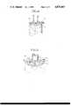
- a conventional, prior art, ion-exchange columnis identified by reference numeral 10 in FIG. 2.
- the ion-exchange columnhas a fluid inlet 12 for introduction of the reaction solution from which the conjugated antibody is to be isolated.
- the isolated, conjugated antibodyexits the ion-exchange column through a fluid outlet 14.
- the ion-exchange columncontains an ion-exchange resin 16 which has an affinity for the anionic, unconjugated radioactive material so as to retain this undesirable material in the ion-exchange column while allowing the uncharged, conjugated antibody to pass therethrough.
- the ion-exchange resingives up a harmless anion, such as chlorine, which exits the fluid outlet 14 with the isolated, conjugated antibody).
- the ion-exchange resin 16typically comprises a polymer material which binds quaternary amino ethyl crystals (such as QAE-Sephadex) together.
- the ion-exchange resin 16Prior to introduction of the reaction solution into the fluid inlet 12, the ion-exchange resin 16 is hydrated with a buffer solution.
- the buffer solutionmaintains a relatively narrow pH range within the ion-exchange column during passage of the reaction solution therethrough.
- the ion-exchange resinwas the consistency of a tacky powder.
- the ion-exchange resinassumes the consistency of a slurry.
- hard fibrous inserts or "frits" 18, 20are positioned adjacent to the fluid inlet 12 and fluid outlet 14, respectively.
- the insert 20 adjacent to the outlet 14also traps fine particles which result from degradation of the ion-exchange resin itself.
- the ion-exchange resinis in the form of a crystalline solid before hydration, and is in the form of a crystalline solid in solution when hydrated.
- the solid particles of the ion-exchange resinare relatively fragile and swell or contract by osmotic action according to the pH of the buffer solution introduced through the fluid inlet 12. It is highly desirable for all of the solution entering the fluid inlet 12 to fully contact the ion-exchange resin 16 before leaving the fluid outlet 14.
- the ion-exchange resinis relatively tightly packed into the ion-exchange column between the hard inserts 18,20 to minimize the formation of voids and fluid channels in the reaction medium during operation of the ion-exchange column.
- the crystalsbegin to fracture and form fine particles ("fines"). These "fines" are trapped in the insert 20 and do not exit the fluid outlet 14.
- the insert 20may eventually become clogged with these fine particles diminishing the efficacy of the column even though the ion exchange medium remains functional.
- undesirable voidsare formed in the ion exchange resin when the resin contracts. Therefore, a need exists for a vertical reaction vessel which can accommodate volumetric changes of an ion-exchange resin contained therein.
- fluid flow distribution irregularitiesare associated with this device.
- the fluid inlet 12 and fluid outlet 14are provided with conventional Luer locks 22 and 24, respectively, having internal diameters 26, 28 which are limited by the outer diameter of a standard Luer lock.
- the diameter 30 and length 32 of a reaction chamber 34 containing the ion-exchange resin 16are determined by the desired flow rate of the reaction solution through the ion-exchange column.
- the diameter 30 of the reaction chamber 34is significantly larger than the inner diameters 26, 28 of the fluid inlet and outlet to accommodate a desired flow rate through the ion-exchange resin 16.
- the reaction solutiontends to form a conical fluid distribution 36, as shown in FIG. 2, which does not provide a desired, uniform fluid flow across the entire cross-sectional area of the reaction chamber. A uniform fluid flow is necessary to provide a uniform exposure for all of the reaction fluid flowing through the column.
- the fluid on the outside of the conical distributionhas a longer travel path through the ion-exchange resin 16 and a greater period of exposure to the ion-exchange resin than does fluid passing through the center of the distribution.
- circled areas 38 and 40 of the ion-exchange resinreceive little, if any, fluid flow and thus do not react with the reaction solution. Therefore, a need exists for a vertical reaction vessel which promotes a uniform fluid flow throughout the entire cross section of the ion-exchange resin.
- the inventionachieves these objects, and other objects and advantages which will become apparent from the description which follows, by providing a vertical reaction vessel with manifold distribution chambers above and below the reaction medium and resilient inserts which expand and contract to accommodate volumetric changes in the reaction medium.
- a preferred embodiment of the inventionincludes an ion-exchange column having a body which partially confines a reaction medium in a reaction chamber.
- the bodyhas a fluid inlet and a fluid outlet substantially smaller in cross-sectional area than the reaction chamber.
- Adjacent to the fluid inlet and fluid outletare manifold fluid distribution chambers which distribute fluid from the fluid inlet and to the fluid outlet throughout the entire cross section of the reaction chamber.
- Resilient membranes, adjacent to the manifold fluid distribution chambersprevent the reaction medium from exiting the body through either the fluid inlet or fluid outlet.
- the resilient membranesexpand when hydrated and have sufficient reserve expansion capacity to fill up any gaps or voids which form when the reaction medium contracts.
- the resilient membranesalso have sufficient resiliency to cushion the reaction medium when the reaction medium expands.
- the inventionalso comprises a method for compensating for volumetric changes in a reaction medium and a method for distributing a solution across the entire cross-sectional area of a reaction medium.
- FIG. 1is a sectional, elevational view of an ion-exchange column employing the manifold distribution chambers and resilient membranes of the present invention.
- FIG. 2is a partial, sectional, elevational view of a prior art ion-exchange column.
- FIGS. 3a through 3care schematic representations of the resilient membranes of the present invention.
- FIG. 3ashows the thickness of the membrane when unhydrated.
- FIG. 3bshows the thickness of the membrane when hydrated.
- FIG. 3cshows the hydrated thickness of the resilient membrane when positioned between the fluid distribution manifold and the ion-exchange resin in the ion-exchange column.
- FIG. 4is a sectional view taken along line 4--4 of FIG. 1.
- FIG. 5is an enlarged, sectional, isometric view of the manifold distribution chamber adjacent to the inlet.
- FIG. 6is an enlarged, sectional, elevational view of the inlet end of the ion-exchange column.
- a preferred embodiment of an ion-exchange column in accordance with the present inventionis generally indicated at reference numeral 50 in FIG. 1.
- the columnhas a hollow cylindrical body 52 which defines a receptacle 54 for a reaction medium 56.
- the columnhas a fluid inlet 58 and a fluid outlet 60 at opposing ends thereof.
- the fluid inlet and fluid outlethave female 62 and male 64 Luer locks of the conventional design.
- the reaction medium 56can be any type of reaction medium.
- an ion-exchange mediumsuch as quaternary amino ethyl Sephadex (QAE-Sephadex) or a diethyl aminoethyl Sephadex (DEAE-Sephadex) electrolyte.
- QAE-Sephadexquaternary amino ethyl Sephadex
- DEAE-Sephadexdiethyl aminoethyl Sephadex
- This reaction mediumis effective in removing electrically charged impurities from a reaction solution (e.g., sodium pertechnetate, technetium dioxide and the hydrolyzed--i.e., carboxylate--form of chelate).
- a reaction solution containing an electrically neutral antibody conjugate of interest and the negatively charged impuritiesis introduced into the fluid inlet 58 by a syringe 70.
- a buffer solutionis introduced into the reaction medium 56 through the fluid inlet 58 to hydrolyze the reaction medium.
- the individual crystals of the reaction mediumexpand or contract through osmotic action according to the pH of the buffer solution.
- resilient membranes 76, 78are positioned adjacent inlet and outlet ends 80, 82 containing the reaction medium therebetween.
- the reaction mediumhas an unhydrolyzed thickness of approximately 0.090 inch.
- the mediumWhen hydrolyzed, such as with a buffer solution, the medium will expand to a thickness of approximately 0.150 inch, if unrestrained.
- the reaction mediumis, however, constrained between radially extending fins 90 and the reaction medium 56 so that in areas 92 between the fins the resilient membrane 76 expands to a thickness of approximately 0.110 inch. At the position of the fins 90, the resilient membrane is compressed to a lesser thickness.
- the resilient membranehas the capacity to expand towards the reaction medium a distance of approximately 0.040 inch at either end of the reaction chamber 54 to compensate for contraction of the ion-exchange resin if the pH of the buffer solution is relatively large.
- the resilient membraneshave the capability to compress approximately 0.020 inch at each end of the reaction chamber when the ion-exchange resin 16 expands if the pH of the buffer solution is low.
- the resilient nature of the resilient membranes 76,78is also effective in providing a radial seating force against the receptacle 54 which holds the membranes in place during wet sterilization procedure.
- the fluid inlet 58 and fluid outlet 60have respective inner diameters 84, 86 which are limited by the standard outer dimensions of the conventional Luer locks.
- the reaction receptacle 54has a substantially constant diameter which is significantly larger than these inner diameters so as to provide a satisfactory flow rate of reaction solution through the ion-exchange column. A flow rate of 10 milliliters solution per minute is considered acceptable.
- the inlet and outlet ends 80, 82 of the ion-exchange columnare provided with the radially extending fins 90. As shown in FIGS. 5 and 6, the fins cooperate with the resilient membrane 76, 78 to form manifold distribution chambers for the reaction fluid.
- the resilient membranes 76, 78provide a relatively high resistance to fluid flow in the direction of the axis 100 of the ion-exchange column 50.
- the fins 90extend radially from the fluid inlet 58 and fluid outlet 60 and have a height 110 sufficient to provide a gap 112 between ends of the reaction chambers 80, 82 and the resilient membranes 76, 78 so as to form radial fluid passageways therebetween. These passageways extend from the fluid inlet to the perimeter of the reaction chamber at the inlet end of the ion-exchange column, and from the perimeter of the reaction chamber to the fluid outlet at the outlet end of the ion-exchange column.
- the fluid passagewayshave a relatively low resistance to fluid flow in the radial direction as compared to fluid flow through the resilient membranes in the axial direction.
- the passagewayscooperate with the resilient membranes to act as fluid distribution manifolds.
- the manifold adjacent the inlet end 80 of the ion-exchange column 50distributes fluid evenly across the entire cross section of the reaction chamber when the reaction fluid enters the fluid inlet.
- the manifold adjacent to the outlet end 82 of the ion-exchange columncollects fluid from the entire cross section of the reaction chamber before the fluid exits the fluid outlet.
- any suitably porous, resilient membrane exhibiting the characteristics shown in FIGS. 3a through 3cis suitable for use as the resilient membranes 76, 78 in the ion-exchange column 50 of the present invention.
- the preferred materialis a rolled and pressed cellulose depth filter; and appropriate item is grade 01AP cellulose manufactured by Cuno, Inc., Meriden, Conn.
- the fluid passageways generally indicated at reference numeral 114are defined by the radial pattern of the fins 90 and the swollen shape of the resilient membrane 76.
- Other fluid passageway shapesare possible which can also achieve uniform fluid distribution over the cross-sectional area of the reaction chamber. Therefore, the invention is not to be limited by the above description but is to be determined in scope by the claims which follow.
Landscapes
- Chemical & Material Sciences (AREA)
- Chemical Kinetics & Catalysis (AREA)
- Organic Chemistry (AREA)
- Analytical Chemistry (AREA)
- General Health & Medical Sciences (AREA)
- Health & Medical Sciences (AREA)
- Life Sciences & Earth Sciences (AREA)
- Biochemistry (AREA)
- Physics & Mathematics (AREA)
- General Physics & Mathematics (AREA)
- Immunology (AREA)
- Pathology (AREA)
- Devices And Processes Conducted In The Presence Of Fluids And Solid Particles (AREA)
- Physical Or Chemical Processes And Apparatus (AREA)
- Medicines Containing Antibodies Or Antigens For Use As Internal Diagnostic Agents (AREA)
- Treatment Of Liquids With Adsorbents In General (AREA)
Abstract
Description
Claims (19)
Priority Applications (5)
| Application Number | Priority Date | Filing Date | Title |
|---|---|---|---|
| US07/235,375US4871463A (en) | 1988-08-23 | 1988-08-23 | Vertical reaction vessel |
| CA000615527ACA1324877C (en) | 1988-08-23 | 1989-09-29 | Vertical reaction vessel |
| EP89911918AEP0446213A1 (en) | 1988-08-23 | 1989-10-02 | Vertical reaction vessel |
| JP51104489AJP3190657B2 (en) | 1988-08-23 | 1989-10-02 | Vertical reaction vessel |
| PCT/US1989/004316WO1991004792A1 (en) | 1988-08-23 | 1989-10-02 | Vertical reaction vessel |
Applications Claiming Priority (2)
| Application Number | Priority Date | Filing Date | Title |
|---|---|---|---|
| US07/235,375US4871463A (en) | 1988-08-23 | 1988-08-23 | Vertical reaction vessel |
| CA000615527ACA1324877C (en) | 1988-08-23 | 1989-09-29 | Vertical reaction vessel |
Publications (1)
| Publication Number | Publication Date |
|---|---|
| US4871463Atrue US4871463A (en) | 1989-10-03 |
Family
ID=25673222
Family Applications (1)
| Application Number | Title | Priority Date | Filing Date |
|---|---|---|---|
| US07/235,375Expired - LifetimeUS4871463A (en) | 1988-08-23 | 1988-08-23 | Vertical reaction vessel |
Country Status (5)
| Country | Link |
|---|---|
| US (1) | US4871463A (en) |
| EP (1) | EP0446213A1 (en) |
| JP (1) | JP3190657B2 (en) |
| CA (1) | CA1324877C (en) |
| WO (1) | WO1991004792A1 (en) |
Cited By (69)
| Publication number | Priority date | Publication date | Assignee | Title |
|---|---|---|---|---|
| WO1991004792A1 (en)* | 1988-08-23 | 1991-04-18 | Sepratech | Vertical reaction vessel |
| WO1995001566A1 (en)* | 1993-06-29 | 1995-01-12 | Bio-Rad Laboratories, Inc. | System for benzodiazepine detection |
| US5439593A (en)* | 1992-09-03 | 1995-08-08 | Hewlett-Packard Company | Solid phase extraction apparatus |
| EP0699477A1 (en)* | 1994-09-05 | 1996-03-06 | Agfa-Gevaert N.V. | Silver recovery device and process |
| US5695989A (en)* | 1990-10-18 | 1997-12-09 | Cellpro, Inc. | Apparatus and method for separating particles using a pliable vessel |
| WO1998001223A1 (en)* | 1996-07-10 | 1998-01-15 | John Yeiser | Lightweight portable device for converting tap water into a spray of demineralized water |
| US5725777A (en)* | 1991-12-16 | 1998-03-10 | Prismedical Corporation | Reagent/drug cartridge |
| EP0906746A3 (en)* | 1997-09-19 | 1999-05-19 | AWECO Kunststofftechnik Gerätebau GmbH & Co. KG | Device for water softening |
| US5951855A (en)* | 1996-12-06 | 1999-09-14 | Chemical Engineering Corporation | Filter and hydraulic mixing assembly for water treatment |
| US5989237A (en) | 1997-12-04 | 1999-11-23 | Baxter International Inc. | Sliding reconstitution device with seal |
| US6020186A (en)* | 1990-10-26 | 2000-02-01 | Qiagen Gmbh | Device and process for isolating nucleic acids from cell suspensions |
| US6022339A (en) | 1998-09-15 | 2000-02-08 | Baxter International Inc. | Sliding reconstitution device for a diluent container |
| WO2000025883A1 (en)* | 1998-10-31 | 2000-05-11 | Amersham Pharmacia Biotech Ab | A new system and its units |
| WO2000051705A1 (en)* | 1999-03-03 | 2000-09-08 | Prismedical Corporation | Methods and devices for preparing hemodialysis solutions |
| US6274103B1 (en) | 1999-03-26 | 2001-08-14 | Prismedical Corporation | Apparatus and method for preparation of a peritoneal dialysis solution |
| US6428505B1 (en) | 1999-11-19 | 2002-08-06 | Prismedical Corporation | In-line IV drug delivery pack with controllable dilution |
| WO2003008064A1 (en)* | 2001-07-19 | 2003-01-30 | Weatherford/Lamb, Inc. | Distributor/collector system |
| US6524484B2 (en) | 1994-10-03 | 2003-02-25 | Amersham Pharmacia Biotech Ab | Access valve devices, their use in separation apparatus, and corresponding methods |
| US6527738B1 (en) | 1999-04-30 | 2003-03-04 | Prismedical Corporation | Drug delivery pack |
| US6582415B1 (en) | 1998-09-15 | 2003-06-24 | Thomas A. Fowles | Sliding reconstitution device for a diluent container |
| US6605214B1 (en) | 1999-03-03 | 2003-08-12 | Prismedical Corporation | Devices for preparing hemodialysis solutions |
| EP1152790A4 (en)* | 1999-02-16 | 2003-10-22 | Prismedical Corp | Single dose delivery device |
| US20040228769A1 (en)* | 2001-05-04 | 2004-11-18 | Taylor Michael A. | Dual chamber dissolution container with passive agitation |
| US20040232079A1 (en)* | 2001-05-14 | 2004-11-25 | Taylor Michael A. | Powered sterile solution device |
| US20060083663A1 (en)* | 2004-10-19 | 2006-04-20 | Ricker Robert D | Fluid processing devices with multiple sealing mechanisms and automated methods of use thereof |
| US7074216B2 (en) | 1998-09-15 | 2006-07-11 | Baxter International Inc. | Sliding reconstitution device for a diluent container |
| US7115423B1 (en) | 1999-10-22 | 2006-10-03 | Agilent Technologies, Inc. | Fluidic structures within an array package |
| US7358505B2 (en) | 1998-09-15 | 2008-04-15 | Baxter International Inc. | Apparatus for fabricating a reconstitution assembly |
| US7425209B2 (en) | 1998-09-15 | 2008-09-16 | Baxter International Inc. | Sliding reconstitution device for a diluent container |
| US7641851B2 (en) | 2003-12-23 | 2010-01-05 | Baxter International Inc. | Method and apparatus for validation of sterilization process |
| US20100222560A1 (en)* | 2009-03-02 | 2010-09-02 | Zymo Research Corporation | Universal column |
| US20130098826A1 (en)* | 2011-10-21 | 2013-04-25 | Mann+Hummel Gmbh | Treatment Unit for Treating a Cooling Fluid of a Cooling Device of a Functional System |
| WO2014181328A1 (en)* | 2013-05-10 | 2014-11-13 | Medimop Medical Projects Ltd | Medical devices including vial adapter with inline dry drug module |
| US8979792B2 (en) | 2009-11-12 | 2015-03-17 | Medimop Medical Projects Ltd. | Inline liquid drug medical devices with linear displaceable sliding flow control member |
| US8998875B2 (en) | 2009-10-01 | 2015-04-07 | Medimop Medical Projects Ltd. | Vial assemblage with vial and pre-attached fluid transfer device |
| USD734868S1 (en) | 2012-11-27 | 2015-07-21 | Medimop Medical Projects Ltd. | Drug vial adapter with downwardly depending stopper |
| USD737436S1 (en) | 2012-02-13 | 2015-08-25 | Medimop Medical Projects Ltd. | Liquid drug reconstitution assembly |
| US20150273356A1 (en)* | 2012-12-14 | 2015-10-01 | Mann+Hummel Gmbh | Ion Exchanger for a Cooling Circuit |
| US9283324B2 (en) | 2012-04-05 | 2016-03-15 | Medimop Medical Projects, Ltd | Fluid transfer devices having cartridge port with cartridge ejection arrangement |
| US9339438B2 (en) | 2012-09-13 | 2016-05-17 | Medimop Medical Projects Ltd. | Telescopic female drug vial adapter |
| USD757933S1 (en) | 2014-09-11 | 2016-05-31 | Medimop Medical Projects Ltd. | Dual vial adapter assemblage |
| USD765837S1 (en) | 2013-08-07 | 2016-09-06 | Medimop Medical Projects Ltd. | Liquid transfer device with integral vial adapter |
| USD767124S1 (en) | 2013-08-07 | 2016-09-20 | Medimop Medical Projects Ltd. | Liquid transfer device with integral vial adapter |
| US9795536B2 (en) | 2012-08-26 | 2017-10-24 | Medimop Medical Projects, Ltd. | Liquid drug transfer devices employing manual rotation for dual flow communication step actuations |
| US9801786B2 (en) | 2013-04-14 | 2017-10-31 | Medimop Medical Projects Ltd. | Drug container closure for mounting on open-topped drug container to form drug reconstitution assemblage for use with needleless syringe |
| USD801522S1 (en) | 2015-11-09 | 2017-10-31 | Medimop Medical Projects Ltd. | Fluid transfer assembly |
| US9839580B2 (en) | 2012-08-26 | 2017-12-12 | Medimop Medical Projects, Ltd. | Liquid drug transfer devices |
| USD832430S1 (en) | 2016-11-15 | 2018-10-30 | West Pharma. Services IL, Ltd. | Dual vial adapter assemblage |
| US10278897B2 (en) | 2015-11-25 | 2019-05-07 | West Pharma. Services IL, Ltd. | Dual vial adapter assemblage including drug vial adapter with self-sealing access valve |
| US10285907B2 (en) | 2015-01-05 | 2019-05-14 | West Pharma. Services IL, Ltd. | Dual vial adapter assemblages with quick release drug vial adapter for ensuring correct usage |
| US10357429B2 (en) | 2015-07-16 | 2019-07-23 | West Pharma. Services IL, Ltd. | Liquid drug transfer devices for secure telescopic snap fit on injection vials |
| US10646404B2 (en) | 2016-05-24 | 2020-05-12 | West Pharma. Services IL, Ltd. | Dual vial adapter assemblages including identical twin vial adapters |
| US10688295B2 (en) | 2013-08-07 | 2020-06-23 | West Pharma. Services IL, Ltd. | Liquid transfer devices for use with infusion liquid containers |
| US10765604B2 (en) | 2016-05-24 | 2020-09-08 | West Pharma. Services IL, Ltd. | Drug vial adapter assemblages including vented drug vial adapter and vented liquid vial adapter |
| US10772798B2 (en) | 2016-12-06 | 2020-09-15 | West Pharma Services Il, Ltd. | Liquid transfer device with integral telescopic vial adapter for use with infusion liquid container and discrete injection vial |
| US10806671B2 (en) | 2016-08-21 | 2020-10-20 | West Pharma. Services IL, Ltd. | Syringe assembly |
| US10806667B2 (en) | 2016-06-06 | 2020-10-20 | West Pharma. Services IL, Ltd. | Fluid transfer devices for filling drug pump cartridges with liquid drug contents |
| US10945921B2 (en) | 2017-03-29 | 2021-03-16 | West Pharma. Services IL, Ltd. | User actuated liquid drug transfer devices for use in ready-to-use (RTU) liquid drug transfer assemblages |
| USD917693S1 (en) | 2018-07-06 | 2021-04-27 | West Pharma. Services IL, Ltd. | Medication mixing apparatus |
| USD923812S1 (en) | 2019-01-16 | 2021-06-29 | West Pharma. Services IL, Ltd. | Medication mixing apparatus |
| USD923782S1 (en) | 2019-01-17 | 2021-06-29 | West Pharma. Services IL, Ltd. | Medication mixing apparatus |
| DE102020208801A1 (en) | 2020-07-15 | 2022-01-20 | Mahle International Gmbh | Ion exchanger for a fuel cell system |
| USD954253S1 (en) | 2019-04-30 | 2022-06-07 | West Pharma. Services IL, Ltd. | Liquid transfer device |
| USD956958S1 (en) | 2020-07-13 | 2022-07-05 | West Pharma. Services IL, Ltd. | Liquid transfer device |
| EP3921070A4 (en)* | 2019-02-07 | 2022-11-02 | Uop Llc | WATER TREATMENT REACTOR INTERNAL WITH REDUCED HEIGHT |
| US11642285B2 (en) | 2017-09-29 | 2023-05-09 | West Pharma. Services IL, Ltd. | Dual vial adapter assemblages including twin vented female vial adapters |
| US11918542B2 (en) | 2019-01-31 | 2024-03-05 | West Pharma. Services IL, Ltd. | Liquid transfer device |
| US12274670B2 (en) | 2019-04-09 | 2025-04-15 | West Pharma. Services IL, Ltd. | Liquid transfer device with integrated syringe |
| US12427091B2 (en) | 2019-01-18 | 2025-09-30 | West Pharma. Services IL, Ltd. | Liquid transfer devices for use with intravenous (IV) bottles |
Families Citing this family (1)
| Publication number | Priority date | Publication date | Assignee | Title |
|---|---|---|---|---|
| JP3937300B2 (en)* | 2001-11-30 | 2007-06-27 | 株式会社日立ハウステック | Cation exchange resin storage cartridge outer case |
Citations (1)
| Publication number | Priority date | Publication date | Assignee | Title |
|---|---|---|---|---|
| US3965000A (en)* | 1972-11-16 | 1976-06-22 | Industrial Filter & Pump Mfg. Co. | Method for operating ion exchange columns |
Family Cites Families (6)
| Publication number | Priority date | Publication date | Assignee | Title |
|---|---|---|---|---|
| AT311902B (en)* | 1970-04-29 | 1973-10-15 | Herrmann W | ION EXCHANGE FILTERS, IN PARTICULAR SMALL FILTERS |
| US4264449A (en)* | 1977-09-21 | 1981-04-28 | American National Red Cross | Antibody-specific solid phase immunoadsorbent, preparation thereof, and antibody purification therewith |
| DE2752581C2 (en)* | 1977-11-25 | 1979-12-13 | Wolfgang 4044 Kaarst Keil | Device for the complete demineralisation of water |
| US4253995A (en)* | 1980-02-11 | 1981-03-03 | Scripps Clinic And Research Foundation | Immunochemical conjugates: method and composition |
| CA1247329A (en)* | 1985-05-06 | 1988-12-28 | Craig J. Brown | Fluid treatment process and apparatus |
| US4871463A (en)* | 1988-08-23 | 1989-10-03 | Sepratech | Vertical reaction vessel |
- 1988
- 1988-08-23USUS07/235,375patent/US4871463A/ennot_activeExpired - Lifetime
- 1989
- 1989-09-29CACA000615527Apatent/CA1324877C/ennot_activeExpired - Lifetime
- 1989-10-02JPJP51104489Apatent/JP3190657B2/ennot_activeExpired - Fee Related
- 1989-10-02WOPCT/US1989/004316patent/WO1991004792A1/ennot_activeApplication Discontinuation
- 1989-10-02EPEP89911918Apatent/EP0446213A1/ennot_activeWithdrawn
Patent Citations (1)
| Publication number | Priority date | Publication date | Assignee | Title |
|---|---|---|---|---|
| US3965000A (en)* | 1972-11-16 | 1976-06-22 | Industrial Filter & Pump Mfg. Co. | Method for operating ion exchange columns |
Cited By (126)
| Publication number | Priority date | Publication date | Assignee | Title |
|---|---|---|---|---|
| WO1991004792A1 (en)* | 1988-08-23 | 1991-04-18 | Sepratech | Vertical reaction vessel |
| US5695989A (en)* | 1990-10-18 | 1997-12-09 | Cellpro, Inc. | Apparatus and method for separating particles using a pliable vessel |
| US6020186A (en)* | 1990-10-26 | 2000-02-01 | Qiagen Gmbh | Device and process for isolating nucleic acids from cell suspensions |
| WO1998035752A1 (en)* | 1991-12-16 | 1998-08-20 | Prismedical Corporation | Reagent cartridge |
| US5725777A (en)* | 1991-12-16 | 1998-03-10 | Prismedical Corporation | Reagent/drug cartridge |
| US5439593A (en)* | 1992-09-03 | 1995-08-08 | Hewlett-Packard Company | Solid phase extraction apparatus |
| AU668824B2 (en)* | 1993-06-29 | 1996-05-16 | Bio-Rad Laboratories, Inc. | System for benzodiazepine detection |
| WO1995001566A1 (en)* | 1993-06-29 | 1995-01-12 | Bio-Rad Laboratories, Inc. | System for benzodiazepine detection |
| US5605632A (en)* | 1994-09-05 | 1997-02-25 | Agfa-Gevaert N.V. | Silver recovery device and process |
| EP0699477A1 (en)* | 1994-09-05 | 1996-03-06 | Agfa-Gevaert N.V. | Silver recovery device and process |
| US20030098280A1 (en)* | 1994-10-03 | 2003-05-29 | John Davis | Access valve devices, their use in separation apparatus, and corresponding methods |
| US6524484B2 (en) | 1994-10-03 | 2003-02-25 | Amersham Pharmacia Biotech Ab | Access valve devices, their use in separation apparatus, and corresponding methods |
| US6719899B2 (en) | 1994-10-03 | 2004-04-13 | Amersham Biosciences Ab | Access valve devices, their use in separation apparatus, and corresponding methods |
| WO1998001223A1 (en)* | 1996-07-10 | 1998-01-15 | John Yeiser | Lightweight portable device for converting tap water into a spray of demineralized water |
| US5951855A (en)* | 1996-12-06 | 1999-09-14 | Chemical Engineering Corporation | Filter and hydraulic mixing assembly for water treatment |
| EP0906746A3 (en)* | 1997-09-19 | 1999-05-19 | AWECO Kunststofftechnik Gerätebau GmbH & Co. KG | Device for water softening |
| US6071270A (en) | 1997-12-04 | 2000-06-06 | Baxter International Inc. | Sliding reconstitution device with seal |
| US6063068A (en) | 1997-12-04 | 2000-05-16 | Baxter International Inc. | Vial connecting device for a sliding reconstitution device with seal |
| US6610040B1 (en) | 1997-12-04 | 2003-08-26 | Baxter International Inc. | Sliding reconstitution device with seal |
| US6090092A (en) | 1997-12-04 | 2000-07-18 | Baxter International Inc. | Sliding reconstitution device with seal |
| US6090091A (en) | 1997-12-04 | 2000-07-18 | Baxter International Inc. | Septum for a sliding reconstitution device with seal |
| US5989237A (en) | 1997-12-04 | 1999-11-23 | Baxter International Inc. | Sliding reconstitution device with seal |
| US6019750A (en) | 1997-12-04 | 2000-02-01 | Baxter International Inc. | Sliding reconstitution device with seal |
| US6852103B2 (en) | 1997-12-04 | 2005-02-08 | Baxter International Inc. | Sliding reconstitution device with seal |
| US6159192A (en) | 1997-12-04 | 2000-12-12 | Fowles; Thomas A. | Sliding reconstitution device with seal |
| US8226627B2 (en) | 1998-09-15 | 2012-07-24 | Baxter International Inc. | Reconstitution assembly, locking device and method for a diluent container |
| US7074216B2 (en) | 1998-09-15 | 2006-07-11 | Baxter International Inc. | Sliding reconstitution device for a diluent container |
| US6890328B2 (en) | 1998-09-15 | 2005-05-10 | Baxter International Inc. | Sliding reconstitution device for a diluent container |
| US7425209B2 (en) | 1998-09-15 | 2008-09-16 | Baxter International Inc. | Sliding reconstitution device for a diluent container |
| US7358505B2 (en) | 1998-09-15 | 2008-04-15 | Baxter International Inc. | Apparatus for fabricating a reconstitution assembly |
| US6022339A (en) | 1998-09-15 | 2000-02-08 | Baxter International Inc. | Sliding reconstitution device for a diluent container |
| US6875203B1 (en) | 1998-09-15 | 2005-04-05 | Thomas A. Fowles | Vial connecting device for a sliding reconstitution device for a diluent container |
| US6582415B1 (en) | 1998-09-15 | 2003-06-24 | Thomas A. Fowles | Sliding reconstitution device for a diluent container |
| US6113583A (en) | 1998-09-15 | 2000-09-05 | Baxter International Inc. | Vial connecting device for a sliding reconstitution device for a diluent container |
| WO2000025883A1 (en)* | 1998-10-31 | 2000-05-11 | Amersham Pharmacia Biotech Ab | A new system and its units |
| US6610200B1 (en) | 1998-10-31 | 2003-08-26 | Amersham Biosciences Ab | System and its units |
| US20040015128A1 (en)* | 1999-02-16 | 2004-01-22 | Taylor Michael A. | Single dose delivery device |
| EP1152790A4 (en)* | 1999-02-16 | 2003-10-22 | Prismedical Corp | Single dose delivery device |
| US6932791B2 (en) | 1999-02-16 | 2005-08-23 | Prismedical Corporation | Single dose delivery device |
| US20060115395A1 (en)* | 1999-03-03 | 2006-06-01 | Taylor Michael A | Apparatus and method for preparation of a peritoneal dialysis solution |
| US20050167363A1 (en)* | 1999-03-03 | 2005-08-04 | Taylor Michael A. | Methods and devices for preparing hemodialysis solutions |
| US6605214B1 (en) | 1999-03-03 | 2003-08-12 | Prismedical Corporation | Devices for preparing hemodialysis solutions |
| US20040031741A1 (en)* | 1999-03-03 | 2004-02-19 | Taylor Michael A. | Methods and devices for preparing hemodialysis solutions |
| WO2000051705A1 (en)* | 1999-03-03 | 2000-09-08 | Prismedical Corporation | Methods and devices for preparing hemodialysis solutions |
| US7300636B2 (en) | 1999-03-03 | 2007-11-27 | Prismedical Corporation | Method for producing a dialysate solution |
| US6858139B2 (en) | 1999-03-03 | 2005-02-22 | Prismedical Corporation | Methods and devices for preparing hemodialysis solutions |
| WO2000051704A1 (en)* | 1999-03-03 | 2000-09-08 | Prismedical Corporation | Apparatus and method for preparation of a peritoneal dialysis solution |
| US6426056B2 (en)* | 1999-03-26 | 2002-07-30 | Prismedical Corporation | Apparatus and method for preparation of a peritoneal dialysis solution |
| US6814724B2 (en) | 1999-03-26 | 2004-11-09 | Prismedical Corporation | Water purification pack |
| US6274103B1 (en) | 1999-03-26 | 2001-08-14 | Prismedical Corporation | Apparatus and method for preparation of a peritoneal dialysis solution |
| US6986872B2 (en) | 1999-03-26 | 2006-01-17 | Prismedical Corporation | Apparatus and method for preparation of a peritoneal dialysis solution |
| US6623709B2 (en) | 1999-03-26 | 2003-09-23 | Prismedical Corporation | Apparatus and method for preparation of a peritoneal dialysis solution |
| US6719745B1 (en) | 1999-03-26 | 2004-04-13 | Prismedical Corporation | Water purification pack |
| US20040057885A1 (en)* | 1999-03-26 | 2004-03-25 | Taylor Michael A. | Apparatus and methos for preparation of aperitoneal dialysis solution |
| US20050113796A1 (en)* | 1999-03-26 | 2005-05-26 | Taylor Michael A. | Water purification pack |
| US20060020240A1 (en)* | 1999-04-30 | 2006-01-26 | Jones Eugene C | Method of loading drug delivery pack |
| US6527738B1 (en) | 1999-04-30 | 2003-03-04 | Prismedical Corporation | Drug delivery pack |
| US6916305B2 (en) | 1999-04-30 | 2005-07-12 | Prismedical Corporation | Method of loading drug delivery pack |
| EP1189659A4 (en)* | 1999-04-30 | 2008-06-25 | Prismedical Corp | Improved drug delivery pack |
| US7115423B1 (en) | 1999-10-22 | 2006-10-03 | Agilent Technologies, Inc. | Fluidic structures within an array package |
| US6805685B2 (en) | 1999-11-19 | 2004-10-19 | Prismedical Corporation | In-line IV drug delivery pack with controllable dilution |
| US20040097886A1 (en)* | 1999-11-19 | 2004-05-20 | Taylor Michael A. | In-line IV drug delivery pack with controllable dilution |
| US6676632B2 (en) | 1999-11-19 | 2004-01-13 | Prismedical Corporation | In-line IV drug delivery pack with controllable dilution |
| US6520932B2 (en) | 1999-11-19 | 2003-02-18 | Prismedical Corporation | In-line IV drug delivery pack with controllable dilution |
| US6428505B1 (en) | 1999-11-19 | 2002-08-06 | Prismedical Corporation | In-line IV drug delivery pack with controllable dilution |
| US20040228769A1 (en)* | 2001-05-04 | 2004-11-18 | Taylor Michael A. | Dual chamber dissolution container with passive agitation |
| US6878338B2 (en) | 2001-05-04 | 2005-04-12 | Prismedical Corporation | Dual chamber dissolution container with passive agitation |
| US20070248489A1 (en)* | 2001-05-14 | 2007-10-25 | Prismedical Corp. | Powered sterile solution device |
| US7250619B2 (en) | 2001-05-14 | 2007-07-31 | Prismedical Corporation | Powered sterile solution device |
| US20040232079A1 (en)* | 2001-05-14 | 2004-11-25 | Taylor Michael A. | Powered sterile solution device |
| US20030024885A1 (en)* | 2001-07-19 | 2003-02-06 | Michael Ekholm | Distributor/collector system |
| US6919020B2 (en) | 2001-07-19 | 2005-07-19 | Weatherford/Lamb, Inc. | Distributor/collector system |
| WO2003008064A1 (en)* | 2001-07-19 | 2003-01-30 | Weatherford/Lamb, Inc. | Distributor/collector system |
| US7641851B2 (en) | 2003-12-23 | 2010-01-05 | Baxter International Inc. | Method and apparatus for validation of sterilization process |
| US8022375B2 (en) | 2003-12-23 | 2011-09-20 | Baxter International Inc. | Method and apparatus for validation of sterilization |
| US20060083663A1 (en)* | 2004-10-19 | 2006-04-20 | Ricker Robert D | Fluid processing devices with multiple sealing mechanisms and automated methods of use thereof |
| US20100222560A1 (en)* | 2009-03-02 | 2010-09-02 | Zymo Research Corporation | Universal column |
| US8998875B2 (en) | 2009-10-01 | 2015-04-07 | Medimop Medical Projects Ltd. | Vial assemblage with vial and pre-attached fluid transfer device |
| US9132063B2 (en) | 2009-11-12 | 2015-09-15 | Medimop Medical Projects Ltd. | Inline liquid drug medical devices with linear displaceable sliding flow control member |
| US8979792B2 (en) | 2009-11-12 | 2015-03-17 | Medimop Medical Projects Ltd. | Inline liquid drug medical devices with linear displaceable sliding flow control member |
| CN103199280A (en)* | 2011-10-21 | 2013-07-10 | 曼·胡默尔有限公司 | Processing unit for processing cooling fluid of cooling device of functional system |
| US20130098826A1 (en)* | 2011-10-21 | 2013-04-25 | Mann+Hummel Gmbh | Treatment Unit for Treating a Cooling Fluid of a Cooling Device of a Functional System |
| USD737436S1 (en) | 2012-02-13 | 2015-08-25 | Medimop Medical Projects Ltd. | Liquid drug reconstitution assembly |
| US9283324B2 (en) | 2012-04-05 | 2016-03-15 | Medimop Medical Projects, Ltd | Fluid transfer devices having cartridge port with cartridge ejection arrangement |
| US10299990B2 (en) | 2012-08-26 | 2019-05-28 | West Pharma. Services IL, Ltd. | Liquid drug transfer devices |
| US9839580B2 (en) | 2012-08-26 | 2017-12-12 | Medimop Medical Projects, Ltd. | Liquid drug transfer devices |
| US9795536B2 (en) | 2012-08-26 | 2017-10-24 | Medimop Medical Projects, Ltd. | Liquid drug transfer devices employing manual rotation for dual flow communication step actuations |
| US9339438B2 (en) | 2012-09-13 | 2016-05-17 | Medimop Medical Projects Ltd. | Telescopic female drug vial adapter |
| USD734868S1 (en) | 2012-11-27 | 2015-07-21 | Medimop Medical Projects Ltd. | Drug vial adapter with downwardly depending stopper |
| US20150273356A1 (en)* | 2012-12-14 | 2015-10-01 | Mann+Hummel Gmbh | Ion Exchanger for a Cooling Circuit |
| US9937441B2 (en)* | 2012-12-14 | 2018-04-10 | Mann+Hummel Gmbh | Ion exchanger for a cooling circuit |
| US9801786B2 (en) | 2013-04-14 | 2017-10-31 | Medimop Medical Projects Ltd. | Drug container closure for mounting on open-topped drug container to form drug reconstitution assemblage for use with needleless syringe |
| CN105228676A (en)* | 2013-05-10 | 2016-01-06 | 麦迪麦珀医疗工程有限公司 | Comprise the medical treatment device of the vial adapter with inline dry drug assembly |
| WO2014181328A1 (en)* | 2013-05-10 | 2014-11-13 | Medimop Medical Projects Ltd | Medical devices including vial adapter with inline dry drug module |
| US9943463B2 (en) | 2013-05-10 | 2018-04-17 | West Pharma. Services IL, Ltd. | Medical devices including vial adapter with inline dry drug module |
| USD767124S1 (en) | 2013-08-07 | 2016-09-20 | Medimop Medical Projects Ltd. | Liquid transfer device with integral vial adapter |
| USD765837S1 (en) | 2013-08-07 | 2016-09-06 | Medimop Medical Projects Ltd. | Liquid transfer device with integral vial adapter |
| US10688295B2 (en) | 2013-08-07 | 2020-06-23 | West Pharma. Services IL, Ltd. | Liquid transfer devices for use with infusion liquid containers |
| USD757933S1 (en) | 2014-09-11 | 2016-05-31 | Medimop Medical Projects Ltd. | Dual vial adapter assemblage |
| US10285907B2 (en) | 2015-01-05 | 2019-05-14 | West Pharma. Services IL, Ltd. | Dual vial adapter assemblages with quick release drug vial adapter for ensuring correct usage |
| US10357429B2 (en) | 2015-07-16 | 2019-07-23 | West Pharma. Services IL, Ltd. | Liquid drug transfer devices for secure telescopic snap fit on injection vials |
| USD801522S1 (en) | 2015-11-09 | 2017-10-31 | Medimop Medical Projects Ltd. | Fluid transfer assembly |
| US10278897B2 (en) | 2015-11-25 | 2019-05-07 | West Pharma. Services IL, Ltd. | Dual vial adapter assemblage including drug vial adapter with self-sealing access valve |
| US10646404B2 (en) | 2016-05-24 | 2020-05-12 | West Pharma. Services IL, Ltd. | Dual vial adapter assemblages including identical twin vial adapters |
| US10765604B2 (en) | 2016-05-24 | 2020-09-08 | West Pharma. Services IL, Ltd. | Drug vial adapter assemblages including vented drug vial adapter and vented liquid vial adapter |
| US10806667B2 (en) | 2016-06-06 | 2020-10-20 | West Pharma. Services IL, Ltd. | Fluid transfer devices for filling drug pump cartridges with liquid drug contents |
| US10806671B2 (en) | 2016-08-21 | 2020-10-20 | West Pharma. Services IL, Ltd. | Syringe assembly |
| USD832430S1 (en) | 2016-11-15 | 2018-10-30 | West Pharma. Services IL, Ltd. | Dual vial adapter assemblage |
| US11786443B2 (en) | 2016-12-06 | 2023-10-17 | West Pharma. Services IL, Ltd. | Liquid transfer device with integral telescopic vial adapter for use with infusion liquid container and discrete injection vial |
| US10772798B2 (en) | 2016-12-06 | 2020-09-15 | West Pharma Services Il, Ltd. | Liquid transfer device with integral telescopic vial adapter for use with infusion liquid container and discrete injection vial |
| US10772797B2 (en) | 2016-12-06 | 2020-09-15 | West Pharma. Services IL, Ltd. | Liquid drug transfer devices for use with intact discrete injection vial release tool |
| US10945921B2 (en) | 2017-03-29 | 2021-03-16 | West Pharma. Services IL, Ltd. | User actuated liquid drug transfer devices for use in ready-to-use (RTU) liquid drug transfer assemblages |
| US11642285B2 (en) | 2017-09-29 | 2023-05-09 | West Pharma. Services IL, Ltd. | Dual vial adapter assemblages including twin vented female vial adapters |
| USD917693S1 (en) | 2018-07-06 | 2021-04-27 | West Pharma. Services IL, Ltd. | Medication mixing apparatus |
| USD923812S1 (en) | 2019-01-16 | 2021-06-29 | West Pharma. Services IL, Ltd. | Medication mixing apparatus |
| USD923782S1 (en) | 2019-01-17 | 2021-06-29 | West Pharma. Services IL, Ltd. | Medication mixing apparatus |
| US12427091B2 (en) | 2019-01-18 | 2025-09-30 | West Pharma. Services IL, Ltd. | Liquid transfer devices for use with intravenous (IV) bottles |
| US11918542B2 (en) | 2019-01-31 | 2024-03-05 | West Pharma. Services IL, Ltd. | Liquid transfer device |
| EP3921070A4 (en)* | 2019-02-07 | 2022-11-02 | Uop Llc | WATER TREATMENT REACTOR INTERNAL WITH REDUCED HEIGHT |
| US12274670B2 (en) | 2019-04-09 | 2025-04-15 | West Pharma. Services IL, Ltd. | Liquid transfer device with integrated syringe |
| USD954253S1 (en) | 2019-04-30 | 2022-06-07 | West Pharma. Services IL, Ltd. | Liquid transfer device |
| US11786442B2 (en) | 2019-04-30 | 2023-10-17 | West Pharma. Services IL, Ltd. | Liquid transfer device with dual lumen IV spike |
| US11484470B2 (en) | 2019-04-30 | 2022-11-01 | West Pharma. Services IL, Ltd. | Liquid transfer device with dual lumen IV spike |
| USD1043974S1 (en) | 2019-04-30 | 2024-09-24 | West Pharma. Services IL, Ltd. | Liquid transfer device |
| USD956958S1 (en) | 2020-07-13 | 2022-07-05 | West Pharma. Services IL, Ltd. | Liquid transfer device |
| DE102020208801A1 (en) | 2020-07-15 | 2022-01-20 | Mahle International Gmbh | Ion exchanger for a fuel cell system |
Also Published As
| Publication number | Publication date |
|---|---|
| JPH04503628A (en) | 1992-07-02 |
| EP0446213A1 (en) | 1991-09-18 |
| CA1324877C (en) | 1993-12-07 |
| WO1991004792A1 (en) | 1991-04-18 |
| JP3190657B2 (en) | 2001-07-23 |
Similar Documents
| Publication | Publication Date | Title |
|---|---|---|
| US4871463A (en) | Vertical reaction vessel | |
| US7850635B2 (en) | Low hydraulic resistance cartridge | |
| CN105992599B (en) | Cartridges for cleaning dialysis solutions | |
| DK173397B1 (en) | Methods for preparing liposomes as well as methods for increasing the homogeneity of a population of liposomes | |
| AU543079B2 (en) | Molecular separation column and use thereof | |
| US4013564A (en) | Multipurpose metabolic assist system | |
| CN100467074C (en) | Filter cartridge assemblies and methods of filtering fluids | |
| US7033498B2 (en) | Cartridges useful in cleaning dialysis solutions | |
| EP0956147A1 (en) | Membrane module with hollow fibre membranes arranged in layers | |
| US5015388A (en) | Integrated device for the biospecific purification of a liquid containing cellular elements | |
| CN102655919B (en) | Containers for chromatography media | |
| GB1600997A (en) | Dialysis device | |
| JP2003535618A (en) | Apparatus and method for preparing peritoneal dialysis solution | |
| EP0154620A2 (en) | Structure with membranes having pores extending throughout, process for producing this structure and its uses | |
| CA1135632A (en) | Plasma treatment apparatus | |
| JPH05508803A (en) | adsorption medium | |
| US6022478A (en) | Device and process for the substance-specific treatment of fluids | |
| US4250141A (en) | Column for the removal of undesired substances from a liquid mixture | |
| AU2016322758B2 (en) | Cartridges useful in cleaning dialysis solutions | |
| JPS62243561A (en) | Leucocyte removing filter device | |
| Beauvais et al. | Membranous nephropathy associated with ovarian tumour in a young girl: recovery after removal | |
| Tijssen et al. | A hemoperfusion column based on activated carbon granules coated with an ultrathin membrane of cellulose acetate | |
| TW201206544A (en) | Installation of filter bodies in a container | |
| De Nitti et al. | Choosing new adsorbents for endogenous ultrapure infusion fluid: performances, safety and flow distribution | |
| JPH04232852A (en) | Chromatography cartridge |
Legal Events
| Date | Code | Title | Description |
|---|---|---|---|
| AS | Assignment | Owner name:SEPRATECH, A CORP. OF CA., CALIFORNIA Free format text:ASSIGNMENT OF ASSIGNORS INTEREST.;ASSIGNORS:TAYLOR, MICHAEL A.;ROGLER-BROWN, TIMOTHY;REEL/FRAME:005018/0972;SIGNING DATES FROM 19881207 TO 19890202 | |
| STCF | Information on status: patent grant | Free format text:PATENTED CASE | |
| CC | Certificate of correction | ||
| FPAY | Fee payment | Year of fee payment:4 | |
| AS | Assignment | Owner name:DULESY, INC., TEXAS Free format text:SECURITY INTEREST;ASSIGNOR:SEPRATECH, INC.;REEL/FRAME:006579/0484 Effective date:19930412 | |
| AS | Assignment | Owner name:DULESY, INC., TEXAS Free format text:BILL OF SALE;ASSIGNOR:SEPRATECH, INC.;REEL/FRAME:007476/0297 Effective date:19950501 | |
| FPAY | Fee payment | Year of fee payment:8 | |
| FEPP | Fee payment procedure | Free format text:PAYOR NUMBER ASSIGNED (ORIGINAL EVENT CODE: ASPN); ENTITY STATUS OF PATENT OWNER: SMALL ENTITY | |
| REFU | Refund | Free format text:REFUND PROCESSED. MAINTENANCE FEE HAS ALREADY BEEN PAID (ORIGINAL EVENT CODE: R160); ENTITY STATUS OF PATENT OWNER: SMALL ENTITY | |
| AS | Assignment | Owner name:PRISMEDICAL CORPORATION, CALIFORNIA Free format text:ASSIGNMENT OF ASSIGNORS INTEREST;ASSIGNORS:PRISMEDICAL CORPORATION;PRISM MEDEVICE CORPORATION;SEPRATECH, INC.;REEL/FRAME:010007/0608 Effective date:19960525 Owner name:CRUTENDEN, WALTER, CALIFORNIA Free format text:ASSIGNMENT OF ASSIGNORS INTEREST;ASSIGNOR:DULESY, INC.;REEL/FRAME:010007/0565 Effective date:19960106 | |
| AS | Assignment | Owner name:PRISM MEDEVICE CORPORATION, CALIFORNIA Free format text:ASSIGNMENT OF ASSIGNORS INTEREST;ASSIGNOR:CRUTTENDEN, III., WALTER;REEL/FRAME:010226/0836 Effective date:19951229 | |
| REMI | Maintenance fee reminder mailed | ||
| AS | Assignment | Owner name:CRUTTENDEN, WALTER, III, CALIFORNIA Free format text:SECURITY AGREEMENT;ASSIGNOR:PRISMEDICAL CORPORATION;REEL/FRAME:012134/0297 Effective date:20010717 Owner name:ISS MANAGEMENT D, LLC, CALIFORNIA Free format text:SECURITY AGREEMENT;ASSIGNOR:PRISMEDICAL CORPORATION;REEL/FRAME:012134/0297 Effective date:20010717 | |
| FPAY | Fee payment | Year of fee payment:12 | |
| SULP | Surcharge for late payment | Year of fee payment:11 | |
| AS | Assignment | Owner name:PRISMEDICAL CORPORATION, CALIFORNIA Free format text:TERMINATION OF SECURITY AGREEMENT ('TERMINATION, WAIVER AND AMENDMENT AGREEMENT);ASSIGNORS:CRUTTENDEN, WALTER III;ISS MANAGEMENT D, LLC;REEL/FRAME:017286/0987 Effective date:20020628 | |
| AS | Assignment | Owner name:GF PRIVATE EQUITY GROUP, LLC, COLORADO Free format text:SECURITY AGREEMENT;ASSIGNOR:PRISMEDICAL CORPORATION;REEL/FRAME:022727/0486 Effective date:20081015 |