US4871321A - Electrical connector - Google Patents
Electrical connectorDownload PDFInfo
- Publication number
- US4871321A US4871321AUS07/171,909US17190988AUS4871321AUS 4871321 AUS4871321 AUS 4871321AUS 17190988 AUS17190988 AUS 17190988AUS 4871321 AUS4871321 AUS 4871321A
- Authority
- US
- United States
- Prior art keywords
- housing
- daughter board
- contacts
- combination
- housing piece
- Prior art date
- Legal status (The legal status is an assumption and is not a legal conclusion. Google has not performed a legal analysis and makes no representation as to the accuracy of the status listed.)
- Expired - Lifetime
Links
Images
Classifications
- H—ELECTRICITY
- H01—ELECTRIC ELEMENTS
- H01R—ELECTRICALLY-CONDUCTIVE CONNECTIONS; STRUCTURAL ASSOCIATIONS OF A PLURALITY OF MUTUALLY-INSULATED ELECTRICAL CONNECTING ELEMENTS; COUPLING DEVICES; CURRENT COLLECTORS
- H01R12/00—Structural associations of a plurality of mutually-insulated electrical connecting elements, specially adapted for printed circuits, e.g. printed circuit boards [PCB], flat or ribbon cables, or like generally planar structures, e.g. terminal strips, terminal blocks; Coupling devices specially adapted for printed circuits, flat or ribbon cables, or like generally planar structures; Terminals specially adapted for contact with, or insertion into, printed circuits, flat or ribbon cables, or like generally planar structures
- H01R12/70—Coupling devices
- H01R12/71—Coupling devices for rigid printing circuits or like structures
- H01R12/72—Coupling devices for rigid printing circuits or like structures coupling with the edge of the rigid printed circuits or like structures
- H01R12/722—Coupling devices for rigid printing circuits or like structures coupling with the edge of the rigid printed circuits or like structures coupling devices mounted on the edge of the printed circuits
- H01R12/727—Coupling devices presenting arrays of contacts
Definitions
- This inventionrelates to electrical connectors, and in particular to such devices useful in the connection of backplanes and daughter boards.
- each daughter boarda pair of separately assemblable to connector portions mounted to the daughter board, the connector portions being provided with contacts press-fittable into holes in the daughter board.
- my connector unitincludes addtional means for securing one connector portion to the other, and a metal stiffener plastic block system interconnecting the connector unit and daughter board.
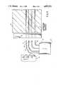
- FIG. 1is an end elevation showing the housing portions of the connector portions of the preferred embodiment in transverse vertical section.
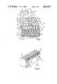
- FIG. 2is an isometric view of the molded plastic housing of said embodiment.
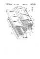
- FIG. 3is a broken-away isometric view of several of said embodiments assembled to a daughter board.
- FIG. 4is an exploded end elevation, partially in section and somewhat diagrammatic, of a step in the assembly.
- Connector 10includes two connector portions 12 and 14 held together by a pair of pins 16 extending respectively at one end (shown in FIG. 1) through holes in protuberances 18 of portion 12 and 22 of portion 14 and at the other end (not shown) through holes in protuberances 18 of portion 14 and 22 of portion 12, a set of such protuberances being provided toward each longitudinal end of said portions.
- the housings 26, 28have the same configuration, as illustrated in FIG. 2, and are engageable as shown in FIG. 1 when their projections 18, 22 are aligned upon rotation of one with respect to the other.
- abutment surfaces 76Longitudinally-extending row of vertical abutment surfaces 76 is provided on molded plastic housings 26, 28 of portions 12, 14, and supports thereon daughter board 30, one larger surface of which abuts abutments 76.
- Contacts 32, 34, 36, 38have upper portions terminating in ends with split portions as disclosed in U.S. Pat. No. Re. 29,513, Johnson, "Electrical Connection Apparatus", issued January 10, 1978, and of overall width of 0.030 inches, press-fitted into 0.025 inch solder-coated holes of daughter board 30, and with lower ends having female portions 24 press-fitted into slots 20 of portions 12, except that contact 38 is secured on the outer part of portion 12 in the manner disclosed in Pat. No. 4,655,518 above mentioned.
- Contacts 40, 42, 44, 46are similarly secured to portion 14 and press-fitted in daughter board 30.
- the holes in daughter board 30 engaging these contactsare vertically staggered from those engaging the contacts from portion 12, each longitudinal row of contacts from portion 14 being halfway between each longitudinal row of contacts from portion 12, except that the highest row of contacts 46 is a corresponding distance above row 38.
- Connector 10is suited to engage a backplane connector element as shown at 16 in said U.S. Pat. No. 4,655,518.
- Stainless steel stiffener 48engages at groove 50 thereof longitudinal protuberance 52 of portion 12.
- Upper portion 54 of stiffener 48is in longitudinally sliding relation with a corresponding slot extending longitudinal through plastic block 56, into which is secured self-threading screw 58, which holds block 56 and daughter board 30 together.
- the horizontal portion 60 of stiffener 48extends before tightening of the screw 58 downwardly in the direction of the daughter board at an angle of 1°, so that on tightening of screw 58 a force in the direction of the daughter board is imposed by stiffener 48 at protuberance 52.
- Each portion 12 and 14is greater in length (i.e., the longitudinal direction) than width (that shown in FIG. 1), and includes a multiplicity of contacts including female portions in longitudinal rows.
- Stiffener 48 and daughter board 30are secured to a plurality of connectors 10.
- Blocks 56are short in the direction longitudinal of the daughter board, stiffener, and connectors 10, and are fewer in number than said connectors.
- contactsare first mounted in their respective housings of portions 12 and 14.
- the contacts from portion 12are then pressed as a group into the respective holes of daughter board 30, using the tool 70 shown in FIG. 3; slots 72 permit the contacts to move thereinto, enabling slots 74 to engage protuberances 62, 64 and drive the contacts press-fittedly into the soldered-through holes provided for them, the insertion stopping upon engagement by the daughter board 30 surface of abutments 76 of housing 26.
- Support 78cooperates with the daughter board 30 to support the latter while the contacts of portion 12 are being inserted.
- the contacts of portion 14are then inserted in daughter board 30, reversing of course the locations of tool 70 and support 78.
- Daughter board 30is supported only by the contacts from portions 12 and 14, being out of contact with any other support both along its face opposite that abutting abutments 76 and along its edge therebetween and above portions 12 and 14.
- the longitudinally outermost contact row nearest each end of each connectoris spaced closely enough to the respective said end that the distance to the outermost contact row adjacent it of the adjacent connector may be the same as the distance between connectors, in a direction longitudinal of the connectors and daughter board, within a connector.
- My inventionhas many mechanical and electrical advantages. Contact length is both shorter and more uniform, and contact mass may be greater, as may contact separation. Inductance, resistance, and cross-talk may be reduced. Reliability is good. Outer rows of contacts 38 and 46, connected to grounding portions 33 and 47 of character the same as the lower portions 36 of said U.S. Pat. No. 4,655,518 provide the entire contact zone with a surrounding shielding.
Landscapes
- Coupling Device And Connection With Printed Circuit (AREA)
- Details Of Connecting Devices For Male And Female Coupling (AREA)
Abstract
Description
Claims (16)
Priority Applications (8)
| Application Number | Priority Date | Filing Date | Title |
|---|---|---|---|
| US07/171,909US4871321A (en) | 1988-03-22 | 1988-03-22 | Electrical connector |
| CA000587920ACA1298366C (en) | 1988-03-22 | 1989-01-11 | Electrical connector |
| IT8967144AIT1232006B (en) | 1988-03-22 | 1989-03-02 | ELECTRIC CONNECTOR |
| SE8900984ASE468695B (en) | 1988-03-22 | 1989-03-20 | ELECTRICAL CONNECTOR |
| DE3909263ADE3909263C3 (en) | 1988-03-22 | 1989-03-21 | Electrical connection device |
| GB8906493AGB2218863B (en) | 1988-03-22 | 1989-03-21 | Electrical connector |
| JP1070317AJPH01272064A (en) | 1988-03-22 | 1989-03-22 | Electric connector |
| FR8903765AFR2629280B1 (en) | 1988-03-22 | 1989-03-22 | CONNECTOR ELEMENT AND COMBINED STRUCTURE COMPRISING THIS ELEMENT AND A CIRCUIT BOARD |
Applications Claiming Priority (1)
| Application Number | Priority Date | Filing Date | Title |
|---|---|---|---|
| US07/171,909US4871321A (en) | 1988-03-22 | 1988-03-22 | Electrical connector |
Publications (1)
| Publication Number | Publication Date |
|---|---|
| US4871321Atrue US4871321A (en) | 1989-10-03 |
Family
ID=22625600
Family Applications (1)
| Application Number | Title | Priority Date | Filing Date |
|---|---|---|---|
| US07/171,909Expired - LifetimeUS4871321A (en) | 1988-03-22 | 1988-03-22 | Electrical connector |
Country Status (8)
| Country | Link |
|---|---|
| US (1) | US4871321A (en) |
| JP (1) | JPH01272064A (en) |
| CA (1) | CA1298366C (en) |
| DE (1) | DE3909263C3 (en) |
| FR (1) | FR2629280B1 (en) |
| GB (1) | GB2218863B (en) |
| IT (1) | IT1232006B (en) |
| SE (1) | SE468695B (en) |
Cited By (34)
| Publication number | Priority date | Publication date | Assignee | Title |
|---|---|---|---|---|
| US5094623A (en)* | 1991-04-30 | 1992-03-10 | Thomas & Betts Corporation | Controlled impedance electrical connector |
| US5307242A (en)* | 1989-08-10 | 1994-04-26 | Siemens Aktiengesellschaft | Device for electrically connecting shieldings of multi-pole plugs to the ground layer of a wiring board |
| US5310364A (en)* | 1992-11-03 | 1994-05-10 | Burndy Corporation | Grounding block |
| US5336098A (en)* | 1992-06-29 | 1994-08-09 | Siemens Aktiengesellschaft | Device for the electrical connection of shieldings of multi-pole plugs to the grounded potential layer of a printed circuit board |
| US5342208A (en)* | 1992-02-19 | 1994-08-30 | Nec Corporation | Package connector apparatus |
| US5397241A (en)* | 1993-10-25 | 1995-03-14 | At&T Corp. | High density electrical connector |
| US5453016A (en)* | 1993-11-15 | 1995-09-26 | Berg Technology, Inc. | Right angle electrical connector and insertion tool therefor |
| US5504989A (en)* | 1993-11-15 | 1996-04-09 | Berg Technology, Inc. | Insertion tool for right angle electrical connector |
| US5549480A (en)* | 1994-05-17 | 1996-08-27 | Tongrand Limited | Unitary connector allowing laterally variant positions of mating contacts of complementary connector |
| US5605476A (en)* | 1993-04-05 | 1997-02-25 | Teradyne, Inc. | Shielded electrical connector |
| US5672064A (en)* | 1995-12-21 | 1997-09-30 | Teradyne, Inc. | Stiffener for electrical connector |
| US5896649A (en)* | 1997-03-26 | 1999-04-27 | The Whitaker Corporation | Seating tool for installing electrical connectors to printed circuit boards |
| US6146202A (en)* | 1998-08-12 | 2000-11-14 | Robinson Nugent, Inc. | Connector apparatus |
| US6231391B1 (en) | 1999-08-12 | 2001-05-15 | Robinson Nugent, Inc. | Connector apparatus |
| US6416335B1 (en)* | 2001-03-16 | 2002-07-09 | Berg Technology Inc. | Stacked surface mount electrical connector and clamping tool |
| US6478624B2 (en) | 2000-06-29 | 2002-11-12 | Robinson Nugent, Inc. | High speed connector |
| US6634889B2 (en)* | 1998-08-03 | 2003-10-21 | Dell Products L.P. | Cross-connected card-edge socket connector and card-edge |
| US6709296B2 (en)* | 1999-11-26 | 2004-03-23 | Advantest Corporation | Modular connector assembly |
| US20050003687A1 (en)* | 2003-05-23 | 2005-01-06 | Yuji Ikeda | Press-fitting head, apparatus and method for press-fitting |
| US6843657B2 (en) | 2001-01-12 | 2005-01-18 | Litton Systems Inc. | High speed, high density interconnect system for differential and single-ended transmission applications |
| US6910897B2 (en) | 2001-01-12 | 2005-06-28 | Litton Systems, Inc. | Interconnection system |
| US6979202B2 (en) | 2001-01-12 | 2005-12-27 | Litton Systems, Inc. | High-speed electrical connector |
| DE10357224B4 (en)* | 2002-12-12 | 2006-06-29 | AutoNetworks Technologies, Ltd., Nagoya | Clamping device for pressing in connections and press-in device |
| US20060194481A1 (en)* | 1998-04-17 | 2006-08-31 | Fci Americas Technology, Inc. | Power connector |
| US20070021000A1 (en)* | 2005-03-31 | 2007-01-25 | Laurx John C | High-density, robust connector with guide means |
| US7549897B2 (en) | 2006-08-02 | 2009-06-23 | Tyco Electronics Corporation | Electrical connector having improved terminal configuration |
| US20090233466A1 (en)* | 2008-03-11 | 2009-09-17 | Delta Electronics, Inc. | Surface-mounted circuit board module and process for fabricating the same |
| US7591655B2 (en) | 2006-08-02 | 2009-09-22 | Tyco Electronics Corporation | Electrical connector having improved electrical characteristics |
| US7670196B2 (en) | 2006-08-02 | 2010-03-02 | Tyco Electronics Corporation | Electrical terminal having tactile feedback tip and electrical connector for use therewith |
| US7753742B2 (en) | 2006-08-02 | 2010-07-13 | Tyco Electronics Corporation | Electrical terminal having improved insertion characteristics and electrical connector for use therewith |
| US8142236B2 (en) | 2006-08-02 | 2012-03-27 | Tyco Electronics Corporation | Electrical connector having improved density and routing characteristics and related methods |
| CN102683980A (en)* | 2011-03-17 | 2012-09-19 | 富士康(昆山)电脑接插件有限公司 | Cable connector assembly |
| US10191510B1 (en)* | 2017-08-18 | 2019-01-29 | Lenovo (Singapore) Pte. Ltd. | Connector substrate assembly, electronic device, and method for assembling electronic device |
| US10290979B2 (en)* | 2017-08-18 | 2019-05-14 | Aptiv Technologies Limited | Electrical connector assembly |
Families Citing this family (2)
| Publication number | Priority date | Publication date | Assignee | Title |
|---|---|---|---|---|
| US4909743A (en)* | 1988-10-14 | 1990-03-20 | Teradyne, Inc. | Electrical connector |
| JP3066570B2 (en)* | 1996-07-26 | 2000-07-17 | モレックス インコーポレーテッド | Method of manufacturing connector assembly for PC card |
Citations (6)
| Publication number | Priority date | Publication date | Assignee | Title |
|---|---|---|---|---|
| US29513A (en)* | 1860-08-07 | Machine for upsetting tires | ||
| USRE29513E (en) | 1974-06-17 | 1978-01-10 | Teradyne, Inc. | Electrical connection apparatus |
| US4550962A (en)* | 1983-05-18 | 1985-11-05 | Erni Elektroapparate Gmbh | Solderless electrical connector assembly |
| US4655518A (en)* | 1984-08-17 | 1987-04-07 | Teradyne, Inc. | Backplane connector |
| US4659155A (en)* | 1985-11-19 | 1987-04-21 | Teradyne, Inc. | Backplane-daughter board connector |
| US4734042A (en)* | 1987-02-09 | 1988-03-29 | Augat Inc. | Multi row high density connector |
Family Cites Families (11)
| Publication number | Priority date | Publication date | Assignee | Title |
|---|---|---|---|---|
| DE2525864C3 (en)* | 1975-06-10 | 1980-01-31 | Siemens Ag, 1000 Berlin Und 8000 Muenchen | Arrangement to increase the number of contacts in connectors of pluggable flat modules |
| US4210379A (en)* | 1979-03-15 | 1980-07-01 | Amp Incorporated | Modular barrier block |
| DE8125321U1 (en)* | 1981-08-31 | 1982-01-14 | Siemens AG, 1000 Berlin und 8000 München | Electrical plug-in assembly |
| US4538877A (en)* | 1982-01-07 | 1985-09-03 | Novis Joseph R | Electrical bridging connector with post separator housing |
| DE3469476D1 (en)* | 1983-12-03 | 1988-03-31 | Mentor Paul Mozar | Front board fitting unit for a circuit board |
| GB2163305B (en)* | 1984-08-17 | 1988-11-02 | Teradyne Inc | Backplane connector |
| EP0177731A3 (en)* | 1984-09-26 | 1987-10-28 | Siemens Aktiengesellschaft | Plug-in electrical module |
| DE8517800U1 (en)* | 1985-06-19 | 1985-08-01 | Siemens AG, 1000 Berlin und 8000 München | Plastic housing for a cable connector |
| JPS6217831A (en)* | 1985-07-16 | 1987-01-26 | Nec Corp | Asynchronous signal generating circuit |
| FR2589286B1 (en)* | 1985-10-25 | 1988-05-13 | Cit Alcatel | ORTHOGONAL PRINTED CIRCUIT BOARD INTERCONNECTION ASSEMBLY AND SWITCHING NETWORKS USING THE SAME |
| FR2606559B1 (en)* | 1986-11-12 | 1990-03-02 | Rech Digitales Sarl Et | MODULAR CONNECTOR |
- 1988
- 1988-03-22USUS07/171,909patent/US4871321A/ennot_activeExpired - Lifetime
- 1989
- 1989-01-11CACA000587920Apatent/CA1298366C/ennot_activeExpired - Lifetime
- 1989-03-02ITIT8967144Apatent/IT1232006B/enactive
- 1989-03-20SESE8900984Apatent/SE468695B/ennot_activeIP Right Cessation
- 1989-03-21DEDE3909263Apatent/DE3909263C3/ennot_activeExpired - Fee Related
- 1989-03-21GBGB8906493Apatent/GB2218863B/ennot_activeExpired - Lifetime
- 1989-03-22FRFR8903765Apatent/FR2629280B1/ennot_activeExpired - Fee Related
- 1989-03-22JPJP1070317Apatent/JPH01272064A/enactivePending
Patent Citations (7)
| Publication number | Priority date | Publication date | Assignee | Title |
|---|---|---|---|---|
| US29513A (en)* | 1860-08-07 | Machine for upsetting tires | ||
| USRE29513E (en) | 1974-06-17 | 1978-01-10 | Teradyne, Inc. | Electrical connection apparatus |
| USRE29513F1 (en) | 1974-06-17 | 1989-04-04 | Teradyne Inc | Electrical connection apparatus |
| US4550962A (en)* | 1983-05-18 | 1985-11-05 | Erni Elektroapparate Gmbh | Solderless electrical connector assembly |
| US4655518A (en)* | 1984-08-17 | 1987-04-07 | Teradyne, Inc. | Backplane connector |
| US4659155A (en)* | 1985-11-19 | 1987-04-21 | Teradyne, Inc. | Backplane-daughter board connector |
| US4734042A (en)* | 1987-02-09 | 1988-03-29 | Augat Inc. | Multi row high density connector |
Non-Patent Citations (2)
| Title |
|---|
| AMP HDI Series 100 Surmount 6 Row Receptacle (Future Center Ground Plane).* |
| AMP HDI™ Series 100 Surmount™ 6 Row Receptacle (Future Center Ground Plane). |
Cited By (55)
| Publication number | Priority date | Publication date | Assignee | Title |
|---|---|---|---|---|
| US5307242A (en)* | 1989-08-10 | 1994-04-26 | Siemens Aktiengesellschaft | Device for electrically connecting shieldings of multi-pole plugs to the ground layer of a wiring board |
| US5094623A (en)* | 1991-04-30 | 1992-03-10 | Thomas & Betts Corporation | Controlled impedance electrical connector |
| US5342208A (en)* | 1992-02-19 | 1994-08-30 | Nec Corporation | Package connector apparatus |
| US5336098A (en)* | 1992-06-29 | 1994-08-09 | Siemens Aktiengesellschaft | Device for the electrical connection of shieldings of multi-pole plugs to the grounded potential layer of a printed circuit board |
| US5310364A (en)* | 1992-11-03 | 1994-05-10 | Burndy Corporation | Grounding block |
| US5605476A (en)* | 1993-04-05 | 1997-02-25 | Teradyne, Inc. | Shielded electrical connector |
| US5607326A (en)* | 1993-04-05 | 1997-03-04 | Teradyne, Inc. | Shielded electrical connector |
| US5397241A (en)* | 1993-10-25 | 1995-03-14 | At&T Corp. | High density electrical connector |
| US5504989A (en)* | 1993-11-15 | 1996-04-09 | Berg Technology, Inc. | Insertion tool for right angle electrical connector |
| US5453016A (en)* | 1993-11-15 | 1995-09-26 | Berg Technology, Inc. | Right angle electrical connector and insertion tool therefor |
| US5549480A (en)* | 1994-05-17 | 1996-08-27 | Tongrand Limited | Unitary connector allowing laterally variant positions of mating contacts of complementary connector |
| US5672064A (en)* | 1995-12-21 | 1997-09-30 | Teradyne, Inc. | Stiffener for electrical connector |
| US5896649A (en)* | 1997-03-26 | 1999-04-27 | The Whitaker Corporation | Seating tool for installing electrical connectors to printed circuit boards |
| US7309242B2 (en)* | 1998-04-17 | 2007-12-18 | Fci Americas Technology, Inc. | Power connector |
| US7488222B2 (en) | 1998-04-17 | 2009-02-10 | Fci Americas Technology, Inc. | Power connector |
| US20060194481A1 (en)* | 1998-04-17 | 2006-08-31 | Fci Americas Technology, Inc. | Power connector |
| US6634889B2 (en)* | 1998-08-03 | 2003-10-21 | Dell Products L.P. | Cross-connected card-edge socket connector and card-edge |
| US6146202A (en)* | 1998-08-12 | 2000-11-14 | Robinson Nugent, Inc. | Connector apparatus |
| US6371813B2 (en) | 1998-08-12 | 2002-04-16 | Robinson Nugent, Inc. | Connector apparatus |
| US6231391B1 (en) | 1999-08-12 | 2001-05-15 | Robinson Nugent, Inc. | Connector apparatus |
| US6709296B2 (en)* | 1999-11-26 | 2004-03-23 | Advantest Corporation | Modular connector assembly |
| US6478624B2 (en) | 2000-06-29 | 2002-11-12 | Robinson Nugent, Inc. | High speed connector |
| US7056128B2 (en) | 2001-01-12 | 2006-06-06 | Litton Systems, Inc. | High speed, high density interconnect system for differential and single-ended transmission systems |
| US7019984B2 (en) | 2001-01-12 | 2006-03-28 | Litton Systems, Inc. | Interconnection system |
| US6910897B2 (en) | 2001-01-12 | 2005-06-28 | Litton Systems, Inc. | Interconnection system |
| US6843657B2 (en) | 2001-01-12 | 2005-01-18 | Litton Systems Inc. | High speed, high density interconnect system for differential and single-ended transmission applications |
| US7101191B2 (en) | 2001-01-12 | 2006-09-05 | Winchester Electronics Corporation | High speed electrical connector |
| US6979202B2 (en) | 2001-01-12 | 2005-12-27 | Litton Systems, Inc. | High-speed electrical connector |
| US6416335B1 (en)* | 2001-03-16 | 2002-07-09 | Berg Technology Inc. | Stacked surface mount electrical connector and clamping tool |
| DE10357224B4 (en)* | 2002-12-12 | 2006-06-29 | AutoNetworks Technologies, Ltd., Nagoya | Clamping device for pressing in connections and press-in device |
| US20050003687A1 (en)* | 2003-05-23 | 2005-01-06 | Yuji Ikeda | Press-fitting head, apparatus and method for press-fitting |
| EP1480298A3 (en)* | 2003-05-23 | 2006-10-18 | Tyco Electronics AMP K.K. | Press fitting head, apparatus and method for press fitting |
| EP1879267A3 (en)* | 2003-05-23 | 2008-02-27 | Tyco Electronics AMP K.K. | Press fitting apparatus and related method |
| EP1879267A2 (en) | 2003-05-23 | 2008-01-16 | Tyco Electronics AMP K.K. | Press fitting apparatus and related method |
| US7243422B2 (en) | 2003-05-23 | 2007-07-17 | Tyco Electronics Amp K.K. | Apparatus for press-fitting |
| US20070021002A1 (en)* | 2005-03-31 | 2007-01-25 | Molex Incorporated | High-density, robust connector |
| US20070021003A1 (en)* | 2005-03-31 | 2007-01-25 | Laurx John C | High-density, robust connector for stacking applications |
| US7320621B2 (en) | 2005-03-31 | 2008-01-22 | Molex Incorporated | High-density, robust connector with castellations |
| US7322856B2 (en) | 2005-03-31 | 2008-01-29 | Molex Incorporated | High-density, robust connector |
| US20070021001A1 (en)* | 2005-03-31 | 2007-01-25 | Laurx John C | High-density, robust connector with castellations |
| US7338321B2 (en) | 2005-03-31 | 2008-03-04 | Molex Incorporated | High-density, robust connector with guide means |
| US20070021000A1 (en)* | 2005-03-31 | 2007-01-25 | Laurx John C | High-density, robust connector with guide means |
| US7621779B2 (en) | 2005-03-31 | 2009-11-24 | Molex Incorporated | High-density, robust connector for stacking applications |
| US7591655B2 (en) | 2006-08-02 | 2009-09-22 | Tyco Electronics Corporation | Electrical connector having improved electrical characteristics |
| US7549897B2 (en) | 2006-08-02 | 2009-06-23 | Tyco Electronics Corporation | Electrical connector having improved terminal configuration |
| US7670196B2 (en) | 2006-08-02 | 2010-03-02 | Tyco Electronics Corporation | Electrical terminal having tactile feedback tip and electrical connector for use therewith |
| US7753742B2 (en) | 2006-08-02 | 2010-07-13 | Tyco Electronics Corporation | Electrical terminal having improved insertion characteristics and electrical connector for use therewith |
| US7789716B2 (en) | 2006-08-02 | 2010-09-07 | Tyco Electronics Corporation | Electrical connector having improved terminal configuration |
| US8142236B2 (en) | 2006-08-02 | 2012-03-27 | Tyco Electronics Corporation | Electrical connector having improved density and routing characteristics and related methods |
| US20090233466A1 (en)* | 2008-03-11 | 2009-09-17 | Delta Electronics, Inc. | Surface-mounted circuit board module and process for fabricating the same |
| CN102683980A (en)* | 2011-03-17 | 2012-09-19 | 富士康(昆山)电脑接插件有限公司 | Cable connector assembly |
| US8523611B2 (en) | 2011-03-17 | 2013-09-03 | Hon Hai Precision Industry Co., Ltd. | Electrical connector having contact modules with differential pairs on both sides of a printed circuit board |
| CN102683980B (en)* | 2011-03-17 | 2014-06-04 | 富士康(昆山)电脑接插件有限公司 | Cable connector assembly |
| US10191510B1 (en)* | 2017-08-18 | 2019-01-29 | Lenovo (Singapore) Pte. Ltd. | Connector substrate assembly, electronic device, and method for assembling electronic device |
| US10290979B2 (en)* | 2017-08-18 | 2019-05-14 | Aptiv Technologies Limited | Electrical connector assembly |
Also Published As
| Publication number | Publication date |
|---|---|
| IT1232006B (en) | 1992-01-22 |
| GB8906493D0 (en) | 1989-05-04 |
| SE8900984L (en) | 1989-09-23 |
| DE3909263A1 (en) | 1989-10-05 |
| FR2629280B1 (en) | 1994-01-28 |
| DE3909263C2 (en) | 1991-04-04 |
| GB2218863B (en) | 1992-09-23 |
| CA1298366C (en) | 1992-03-31 |
| DE3909263C3 (en) | 1997-09-11 |
| IT8967144A0 (en) | 1989-03-02 |
| SE8900984D0 (en) | 1989-03-20 |
| FR2629280A1 (en) | 1989-09-29 |
| SE468695B (en) | 1993-03-01 |
| JPH01272064A (en) | 1989-10-31 |
| GB2218863A (en) | 1989-11-22 |
Similar Documents
| Publication | Publication Date | Title |
|---|---|---|
| US4871321A (en) | Electrical connector | |
| EP0278868B1 (en) | Multi row high density connector | |
| US5046960A (en) | High density connector system | |
| US4955819A (en) | Plug connector having bent contact posts for insertion into printed circuit board holes | |
| US4533203A (en) | Connector for printed circuit boards | |
| US6129592A (en) | Connector assembly having terminal modules | |
| US4806103A (en) | High density edgecard connector system | |
| US6780058B2 (en) | Shielded backplane connector | |
| US6371773B1 (en) | High density interconnect system and method | |
| US5238414A (en) | High-speed transmission electrical connector | |
| US5201662A (en) | Electrical connector for mounting on a printed circuit board | |
| EP1393413B1 (en) | Board connecting connector and method for producing the same | |
| US7503804B2 (en) | Backplane connector | |
| US4331370A (en) | Connection system for printed circuit boards | |
| CA1305761C (en) | Electrical connector | |
| US7300313B1 (en) | Electrical connector having staggered contacts | |
| EP0670616A1 (en) | Connector for a cable for high frequency signals | |
| US5190480A (en) | All-in-one interconnection assembly | |
| US6811414B1 (en) | Electrical connector module with multiple card edge sections | |
| JPH04294079A (en) | Right angle connector for base board and time plate | |
| EP1327288A1 (en) | Shielded backplane connector | |
| US6000955A (en) | Multiple terminal edge connector | |
| EP0342873B1 (en) | Surface mount connector | |
| US5013250A (en) | Multi-pole connector plug | |
| DE602005003447T2 (en) | Electrical connector device |
Legal Events
| Date | Code | Title | Description |
|---|---|---|---|
| AS | Assignment | Owner name:TERADYNE, INC., BOXTON, MASSACHUSETTS A MA CORP. Free format text:ASSIGNMENT OF ASSIGNORS INTEREST.;ASSIGNOR:JOHNSON, LENNART B.;REEL/FRAME:004862/0717 Effective date:19880321 Owner name:TERADYNE, INC., A MA CORP., MASSACHUSETTS Free format text:ASSIGNMENT OF ASSIGNORS INTEREST;ASSIGNOR:JOHNSON, LENNART B.;REEL/FRAME:004862/0717 Effective date:19880321 | |
| STCF | Information on status: patent grant | Free format text:PATENTED CASE | |
| FEPP | Fee payment procedure | Free format text:PAYOR NUMBER ASSIGNED (ORIGINAL EVENT CODE: ASPN); ENTITY STATUS OF PATENT OWNER: LARGE ENTITY | |
| FPAY | Fee payment | Year of fee payment:4 | |
| FEPP | Fee payment procedure | Free format text:PAYER NUMBER DE-ASSIGNED (ORIGINAL EVENT CODE: RMPN); ENTITY STATUS OF PATENT OWNER: LARGE ENTITY Free format text:PAYOR NUMBER ASSIGNED (ORIGINAL EVENT CODE: ASPN); ENTITY STATUS OF PATENT OWNER: LARGE ENTITY | |
| FPAY | Fee payment | Year of fee payment:8 | |
| FPAY | Fee payment | Year of fee payment:12 | |
| AS | Assignment | Owner name:AMPHENOL CORPORATION, CONNECTICUT Free format text:ASSIGNMENT OF ASSIGNORS INTEREST;ASSIGNOR:TERADYNE, INC.;REEL/FRAME:017223/0611 Effective date:20051130 |