US4871316A - Printed wire connector - Google Patents
Printed wire connectorDownload PDFInfo
- Publication number
- US4871316A US4871316AUS07/258,939US25893988AUS4871316AUS 4871316 AUS4871316 AUS 4871316AUS 25893988 AUS25893988 AUS 25893988AUS 4871316 AUS4871316 AUS 4871316A
- Authority
- US
- United States
- Prior art keywords
- modules
- connector
- printed wire
- wire connector
- insulative layer
- Prior art date
- Legal status (The legal status is an assumption and is not a legal conclusion. Google has not performed a legal analysis and makes no representation as to the accuracy of the status listed.)
- Expired - Lifetime
Links
- 239000000758substrateSubstances0.000abstractdescription19
- 239000000463materialSubstances0.000abstractdescription7
- 239000004020conductorSubstances0.000description11
- 238000010276constructionMethods0.000description10
- 238000000034methodMethods0.000description5
- 230000008901benefitEffects0.000description4
- 238000001459lithographyMethods0.000description4
- RYGMFSIKBFXOCR-UHFFFAOYSA-NCopperChemical compound[Cu]RYGMFSIKBFXOCR-UHFFFAOYSA-N0.000description2
- 238000003491arrayMethods0.000description2
- 238000005452bendingMethods0.000description2
- 239000003990capacitorSubstances0.000description2
- 239000000919ceramicSubstances0.000description2
- 229910052802copperInorganic materials0.000description2
- 239000010949copperSubstances0.000description2
- 229910052751metalInorganic materials0.000description2
- 239000002184metalSubstances0.000description2
- 238000012986modificationMethods0.000description2
- 230000004048modificationEffects0.000description2
- 239000010955niobiumSubstances0.000description2
- 230000009466transformationEffects0.000description2
- 239000004642PolyimideSubstances0.000description1
- BTGZYWWSOPEHMM-UHFFFAOYSA-N[O].[Cu].[Y].[Ba]Chemical compound[O].[Cu].[Y].[Ba]BTGZYWWSOPEHMM-UHFFFAOYSA-N0.000description1
- 230000009471actionEffects0.000description1
- 238000004026adhesive bondingMethods0.000description1
- 229910052782aluminiumInorganic materials0.000description1
- XAGFODPZIPBFFR-UHFFFAOYSA-NaluminiumChemical compound[Al]XAGFODPZIPBFFR-UHFFFAOYSA-N0.000description1
- PNEYBMLMFCGWSK-UHFFFAOYSA-Naluminium oxideInorganic materials[O-2].[O-2].[O-2].[Al+3].[Al+3]PNEYBMLMFCGWSK-UHFFFAOYSA-N0.000description1
- 230000008602contractionEffects0.000description1
- 230000001186cumulative effectEffects0.000description1
- 230000001419dependent effectEffects0.000description1
- 230000000694effectsEffects0.000description1
- 239000013536elastomeric materialSubstances0.000description1
- 238000010304firingMethods0.000description1
- -1for exampleSubstances0.000description1
- PCHJSUWPFVWCPO-UHFFFAOYSA-NgoldChemical compound[Au]PCHJSUWPFVWCPO-UHFFFAOYSA-N0.000description1
- 229910052737goldInorganic materials0.000description1
- 239000010931goldSubstances0.000description1
- 238000009413insulationMethods0.000description1
- 238000004519manufacturing processMethods0.000description1
- 230000007246mechanismEffects0.000description1
- 239000007769metal materialSubstances0.000description1
- 150000002739metalsChemical class0.000description1
- 229910052758niobiumInorganic materials0.000description1
- GUCVJGMIXFAOAE-UHFFFAOYSA-Nniobium atomChemical compound[Nb]GUCVJGMIXFAOAE-UHFFFAOYSA-N0.000description1
- 229920001721polyimidePolymers0.000description1
- 229920000642polymerPolymers0.000description1
- 239000002887superconductorSubstances0.000description1
- 238000010408sweepingMethods0.000description1
- 229910021521yttrium barium copper oxideInorganic materials0.000description1
Images


Classifications
- H—ELECTRICITY
- H01—ELECTRIC ELEMENTS
- H01R—ELECTRICALLY-CONDUCTIVE CONNECTIONS; STRUCTURAL ASSOCIATIONS OF A PLURALITY OF MUTUALLY-INSULATED ELECTRICAL CONNECTING ELEMENTS; COUPLING DEVICES; CURRENT COLLECTORS
- H01R12/00—Structural associations of a plurality of mutually-insulated electrical connecting elements, specially adapted for printed circuits, e.g. printed circuit boards [PCB], flat or ribbon cables, or like generally planar structures, e.g. terminal strips, terminal blocks; Coupling devices specially adapted for printed circuits, flat or ribbon cables, or like generally planar structures; Terminals specially adapted for contact with, or insertion into, printed circuits, flat or ribbon cables, or like generally planar structures
- H01R12/70—Coupling devices
- H01R12/71—Coupling devices for rigid printing circuits or like structures
- H01R12/712—Coupling devices for rigid printing circuits or like structures co-operating with the surface of the printed circuit or with a coupling device exclusively provided on the surface of the printed circuit
- H01R12/714—Coupling devices for rigid printing circuits or like structures co-operating with the surface of the printed circuit or with a coupling device exclusively provided on the surface of the printed circuit with contacts abutting directly the printed circuit; Button contacts therefore provided on the printed circuit
Definitions
- the present inventionrelates to a high density, high performance connector for interconnecting elements, and especially, elements having different wiring densities.
- a particular object of the inventionis to provide a high density connector which can interconnect low cost, high volume components, such as printed circuit boards, and high precision components, such as high density multi-chip substrates.
- a further objectis to provide a high density connector of the type above which can connect components positioned at any angle from one another.
- a still further object of the inventionis to provide a connector which is removable.
- An additional object of the inventionis to provide a high density connector having known and well-controlled impedance.
- Still another object of the inventionis to provide a connector in which the impedance can be modified for different technological requirements.
- a printed wire connectorfor connecting circuit elements, comprising at least one module which includes an insulative layer and electrically conductive wires extending across one face of the insulative layer to connect elements at opposite ends of the wires.
- the printed wire connectorincludes a series of the modules stacked one on another.
- the printed wire connectorfurther includes a conductive layer, i.e., either a voltage or ground plane, positioned on the side of the insulative layer opposite the conductive wires, and a second insulative layer on the other side of the conductive layer.
- a conductive layeri.e., either a voltage or ground plane
- the printed wire connectorcan include a plurality of passageways extending through the series of modules and receiving means for aligning the module and for providing contact with certain of the conductive layers.
- the connectoralso can include means for spacing the modules in relation to one another, for example, an elastic member positioned between select modules.
- the present connectoradvantageously utilizes high volume, low cost parts to provide a high density interconnect.
- the connectoron the one hand, accommodates relatively coarse, printed circuit board lithography that is produced by many vendors, while, on the other hand, also accommodates high density substrates.
- the designcan accommodate a variety of wiring densities by varying module and conductor thicknesses. Because the design is modular in nature, a variety of sizes is offered.
- the shape of the connectoris also highly variable to connect between elements positioned at any angle relative to one another.
- the connectoris suitable for very wide bandwidth since the impedance is known and well controlled.
- the connectoris suitable for use with a wide variety of materials, including advantageous insulative and conductive materials.
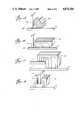
- FIG. 1is an exploded isometric view of an assembly incorporating the connector of the present invention.
- FIG. 2is a top plan view of a connector according to the present invention.
- FIG. 3is a bottom plan view of a connector according to the present invention.
- FIG. 4-7are cross-sectional views of the connector of FIG. 2.
- FIG. 6Ais a cross-sectional view of the bolt and passageway construction of FIG. 6.
- FIG. 8is a cross-sectional view of a bolt construction according to the present invention.
- FIG. 9is a partial cross-sectional view of an aligning jig according to the present invention.
- FIG. 10is an isometric view of a module of a printed wire connector according to the present invention.
- FIG. 11is an isometric view of a printed wire connector having external, surface mounted circuit components.
- FIGS. 12-13are isometric views of a module of a printed wire connector having internal mounted circuit components.
- FIG. 14is a front view of a printed wire conductor in one application according to the present invention.
- FIGS. 15-18are isometric views of alternative designs of printed wire connectors according to the present invention.
- the present inventionis illustrated in FIG. 1.
- the connector 10is positioned between a mother board 12, e.g., a lower density printed circuit (P.c.) board, and a daughter board 14, e.g , a higher density multi-chip substrate.
- the connector 10is formed from a number of modules 16 placed adjacent one another and laminated. Each module includes at least an insulative layer 18 and electrically conductive wires 20 applied to one face of the insulative layer.
- the conductor ends 21 and 23are exposed and specially designed for proper bending moment and proper contact pressure with the pad arrays 22 of the mother board and daughter board 14.
- the mother and daughter boardsan assume any variety of applications and/or densities.
- the mother board 12can be the lower density board, with the daughter board 14 being a high density substrate.
- this design of the boardswill be described below.
- the wires 20are positioned on the insulative layer so as to provide contact points with the lower density p.c. board and, at the same time, with the higher density substrate 14.
- the particular wire patternvaries with the densities of the boards and/or substrates being interconnected.
- the wires 20fan out at the base of the module to register with the pads of the low-density p.c. board.
- the pads 22are more dense than those illustrated in FIG. 1, the wires are etched so that the ends 21 are closer together.
- the wires of adjacent modulescan assume different geometries.
- the wires of the next adjacent module in the connector of FIG. 1can be positioned in such a manner that the ends are closer together to register with more dense pads. Such an embodiment is illustrated in FIGS. 2 and 3.
- FIG. 2is a top view of the connector 10. Adjacent connectors 24 and 26 are shown in partial view. The ends 23 extending from the top of the connector are shown.
- a module 16is shown and referenced by the dimension "x". As previously mentioned, each module includes at least the conductor wires 20 and insulative layer 18. In preferred embodiments, the modules also include a conductive plane 28. The layer 28 can be either a voltage plane or a ground plane. FIG. 2 illustrates both embodiments. The conductive plane 28 is positioned on the side of the insulative layer opposite the conductive wiring. In order to separate and insulate the conductive planes from the adjacent conductive wiring, a further insulative layer 30 is positioned therebetween. Thus, a module according to this embodiment has the following form--conductive wiring/insulative layer/voltage or ground plane/insulative layer. A unit of modules of this construction is shown in FIG. 2 as comprising modules 32, 34 and 36.
- modulescan be placed end-to-end rather than face-to-face as is illustrated in FIG. 2.
- the design choicebeing dependent, of course, on the application.
- FIG. 3illustrates the identical connector construction when viewed from below. Like elements are given the same reference numbers as before. As FIG. 3 shows, the spacing of the ends 21 of the conductor wires can vary from module to module. Module 32 reflects a module having ends which are more closely spaced apart to contact with more dense attach pads. In comparison, the wire ends of the module 34 are spaced farther apart to register with less dense attach pads. Module 36 has a wire geometry like that of module 32. FIGS. 2 and 3 reflect only one of many embodiments of connector wiring architecture which depends simply on the densities of the boards to be interconnected.
- the connectorcan include a flexible spacing connector 38 positioned between select modules.
- the connector 38can be made from an elastomeric or metal material. For example, a rectangular elastomeric cushion or a metal spring can be used.
- the connector 10can be provided with locating pins 40.
- the pins 40extend into a slot formed in the board or substrate and, especially when combined with the flexible connector 38, serve to remedy tolerance and expansion variances between the boards/substrates and connector and, thus, achieve better contact between conductor ends 21 and pad arrays 22.
- the connector 10can include bolts 42 which pass longitudinally through the connectors. Nuts 44 are provided to be screwed onto the bolts to secure the modules. The bolts and passages therefor will be discussed in more detail below in relation to FIGS. 6-9.
- the layers of the connectorcan be joined by a variety of techniques known to the skilled artisan including gluing, firing ceramics, etc.
- the connectorcan be made as a multi-layer printed circuit board with filled vias serving the purposes of the bolts.
- the present designachieves this result by offering variability of thickness and width of the "insulative layer".
- a particular dielectric constantcan be selected and high frequency performance can be achieved. Therefore, by varying the thickness and width of this material of a known dielectric constant, a specific characteristic impedance can be achieved within a range of tolerances.
- the connectorserves to prevent cross-talk, distortion, and ringing between the various layers. Thus, the fidelity of signals passing through the connector can be preserved by an appropriate selection of dielectric and geometric configuration.
- FIGS. 4 and 5illustrate such a design for contacting the ends 21 with the attach pads 22 of the p.c. board 12. Also, a comparison of the conductive wiring of FIGS. 4 and 5 reveals the different wiring construction previously discussed, with FIG. 4 illustrating contact to attach pads 22 which are closer together than those of FIG. 5. Obviously, the wiring 20 can be placed on the insulating layer 18 at any variety of angles, shapes or directions.
- each conductive wireas a unitary structure
- the wiringsuch that the ends 21 and 23 can be applied after the layers are joined. This offers an advantageous assembly procedure whereby the wires are patterned onto the insulative layers which are joined or laminated together. Thereafter, the ends can be attached.
- FIG. 5also illustrates the locating pin/slot arrangement previously discussed and shown by FIGS. 2 and 3.
- the locating pin 40extends from the connector 10 vertically into a receiving slot 46 of the p.c. board 12.
- another pincan extend from the top of the connector and into a slot formed in the substrate 14 (not shown in FIG. 5).
- FIG. 6depicts the provision of three passageways 48, 49 and 50 which extend through the modules.
- the passagewayscan assume any variety of configurations depending primarily on whether the bolt passing therethrough is to contact the conductive plane housing the passageways.
- FIGS. 6, 6A and 7illustrate three alternatives.
- FIG. 6depicts the passageways formed in a voltage plane 53.
- Passageway 48is formed simply by making cross-cuts 47 in the voltage planes.
- the bolt 42then is pressed through the orifice.
- at least four points of contactare developed between the bolt and the voltage plane providing a method of self-centering for the bolts. This provides a level of redundancy, as well as a means for providing multiple voltages through the bolts.
- the passagewaycan be etched or bored to a circumference larger than that of the bolt. Such a construction is shown in Passageways 49 and 50. Cross-cuts 47 in the underlying insulative layers are shown at passageways 49 and 50.
- the conducting planeis cross-cut as in the embodiment above for providing electrical contact.
- the conducting planeis further modified by the provision of a moat or ring 57 formed radically outward of the cross-cut.
- This embodimenthas the advantage that the cross-cuts in the conducting plane provide a spring-like action which assists the centering of the bolts, and the moat or ring prevents electrical flow from the bolt throughout the conducting lane.
- FIG. 6Aillustrates all three embodiments.
- Plane 53comprises cross-cuts 47 which provides contact between the bolt 42 and plane 53.
- Insulative layer 55is designed so that it does not abut the bolt 42. This gives the leaves of the conductive plane 53 formed at the cross-cuts room to bend back as shown.
- Plane 52has also been cross-cut at the point of bolt passage.
- the planecomprises a ring shown in cross-section 57.
- plane 54has been bored away around the bolt. Insulative layers 61 and 63 are cross-cut and are shown sweeping back slightly as a result of the passage of the bolt there through.
- FIG. 7illustrates a similar embodiment to FIG. 6 for the ground plane 52.
- the center bolt 42contacts the ground plane, while the bolts 42 on either side pass through without contacting a conductor.
- FIG. 8illustrates this function.
- the threads of the bolt 42engage the conducting planes 28, thus setting Proper spacing of the module.
- Such a fixturing mechanismis important in assuring alignment of the conductive wiring of the connector and the attach pads of the boards and substrates.
- Such a functionis especially important where many modules are stacked due to the cumulative effect of width variation due to tolerance levels in manufacture of the insulative layer. This effect will be referred to hereafter as "periodicity".
- the bolts 42are only one embodiment of such guides; as another example, an external corrugated box or jig can provide the same function.
- the jig 64registers with the extending conductive planes 28 in the same manner as the bolt of FIG. 8.
- FIG. 10is an isometric view of one module of the present connector. Obviously, if minimal connections are required, the connector can comprise only one such module. As the complexity of the lithography increases, however, the number of modules for the requisite connector also increases.
- An advantage of the present connector architectureis the fact that it is modular and, as such, can comprise a large number of individual modules and thus conductive wiring. The problems of expansion, contraction and Periodicity are accounted for by the joint combination of flexible connectors 38 (see FIG. 2) and registering means, such as the bolts or external jigs.
- the module 66 of FIG. 10consists of a number of conductive wires 20 extending along the face of insulative layer 18. Immediately adjacent insulative layer 18 is a conductive Plane 28. Completing the module 66, a further insulative layer 30 is placed on the other side of the conductive plane 28 to insulate same from the conductive wiring 28.
- the present connector constructionalso provides for modifications to the conductive wiring, either internally on individual modules or externally on the assembled connector.
- FIGS. 11-13illustrate some embodiments of such construction.
- FIG. 11the wiring modifications are done once the connector is assembled.
- decoupling capacitors 68are mounted on the surface of the connector.
- the voltage planes 70 and 72, for possible attachment to the capacitors 68,are also shown.
- FIGS. 12 and 13illustrate the provision of additional components to individual modules.
- termination resistors 76are provided on the face of the insulating layer 18 and in contact with conductive wires 20.
- the resistors 76at their other end, connect to a conducting pattern internal to the module, which, in turn, connects to a terminating reference voltage structure distributed through the passageways 82 in the form of a conducting bolt, a plated-through hole or a via that connects to the voltage plane 74.
- the module 84 of FIG. 13includes surface mounted chips 86.
- the chipsare connected to power and or ground planes by passageways 88.
- Terminating resistors 90are provided in contact with the conductive wiring 20 and are, in turn, connected to the terminating reference voltage plane (not shown) by passageways 92.
- the connector according to the present inventioncan assume a wide variety of applications and designs.
- FIGS. 14-18illustrate some of these embodiments.
- a typical use of the connectoris shown in FIG. 14.
- the connector 94extends between and connects a multichip substrate 96 and a more course, less dense p.c. board 98.
- the chips 100are shown attached to the substrate. Attached to the other side of the chips is a heat sink 102.
- the connectorsare not limited to parallel stacked boards in which the connector extends orthogonal thereto. Instead, the connector can assume any number of shapes to connect boards positioned at any angle relative to one another.
- FIGS. 15-18illustrate possible designs.
- the connector 104extends between perpendicular boards 106 and 108.
- the boardsare schematically shown to have similar densities. Accordingly, the adjacent conductive wiring is parallel, i.e., a space transformation of 1:1.
- the connector 110 of FIG. 16extends between and connects boards of different densities, e.g., a high-density substrate 112 and a less dense p.c. board 114.
- FIGS. 17 and 18show different connector designs serving the same interconnect function as above.
- the connector 116connects parallel boards of different densities; in FIG. 18, the connector 118 connects orthogonal boards of similar densities, wherein the connector has a slot 120 for receiving the vertically extending board.
- the connectorcan interconnect boards at any angle to one another and having a wide varieties of wiring densities.
- the connectors of the present inventionutilize presently available materials.
- the conductive wiring and conducting planecan be formed from a variety of metals, for example, copper, aluminum, gold, and super-conductors such as niobium (Nb) and yttrium barium copper oxide (YBaCuO). Particularly preferred is copper.
- Nbniobium
- YBaCuOyttrium barium copper oxide
- coppercopper
- any of a variety of insulative materialscan be used.
- a number of polymersprovide acceptable insulative properties, including polyimide, FR4, FR5, etc.
- ceramicssuch as alumina can also be used as insulation.
- the present connectoradvantageously utilizes high volume, low cost parts to provide a high density interconnect.
- the connectoron the one hand, accommodates relatively coarse, printed circuit board lithography that is produced by many vendors, while, on the other hand, also accommodates high density substrates.
- the designcan accommodate a variety of wiring densities by varying module and conductor thicknesses. Because the design is modular in nature, a variety of sizes and, thus, connectability is offered.
- the shape of the connectoris also highly variable to connect between elements positioned at any angle relative to one another. Finally, the connector is suitable for a wide bandwidth since the impedance is known and well controlled.
Landscapes
- Coupling Device And Connection With Printed Circuit (AREA)
Abstract
Description
Claims (19)
Priority Applications (1)
| Application Number | Priority Date | Filing Date | Title |
|---|---|---|---|
| US07/258,939US4871316A (en) | 1988-10-17 | 1988-10-17 | Printed wire connector |
Applications Claiming Priority (1)
| Application Number | Priority Date | Filing Date | Title |
|---|---|---|---|
| US07/258,939US4871316A (en) | 1988-10-17 | 1988-10-17 | Printed wire connector |
Publications (1)
| Publication Number | Publication Date |
|---|---|
| US4871316Atrue US4871316A (en) | 1989-10-03 |
Family
ID=22982772
Family Applications (1)
| Application Number | Title | Priority Date | Filing Date |
|---|---|---|---|
| US07/258,939Expired - LifetimeUS4871316A (en) | 1988-10-17 | 1988-10-17 | Printed wire connector |
Country Status (1)
| Country | Link |
|---|---|
| US (1) | US4871316A (en) |
Cited By (76)
| Publication number | Priority date | Publication date | Assignee | Title |
|---|---|---|---|---|
| US4929185A (en)* | 1989-04-03 | 1990-05-29 | Nrc Corporation | Printed circuit board assembly |
| US4997719A (en)* | 1988-10-25 | 1991-03-05 | Ube Industries, Ltd. | Niobium-containing superconductor-laminated aromatic polyimide material |
| US5037311A (en)* | 1989-05-05 | 1991-08-06 | International Business Machines Corporation | High density interconnect strip |
| US5049084A (en)* | 1989-12-05 | 1991-09-17 | Rogers Corporation | Electrical circuit board interconnect |
| US5079221A (en)* | 1988-02-23 | 1992-01-07 | Fujitsu Limited | Superconductor passivated by an organic film and a method for forming the organic film |
| US5295869A (en)* | 1992-12-18 | 1994-03-22 | The Siemon Company | Electrically balanced connector assembly |
| EP0591772A1 (en)* | 1992-10-07 | 1994-04-13 | Fujitsu Limited | High-density/long-via laminated connector |
| US5350594A (en)* | 1993-01-25 | 1994-09-27 | Tech Spray, Inc. | Conformally coated faraday cage |
| US5459643A (en)* | 1993-09-30 | 1995-10-17 | The Siemon Company | Electrically enhanced wiring block with break test capability |
| US5575686A (en)* | 1993-04-14 | 1996-11-19 | Burndy Corporation | Stacked printed circuit boards connected in series |
| US5899755A (en)* | 1996-03-14 | 1999-05-04 | Johnstech International Corporation | Integrated circuit test socket with enhanced noise imminity |
| US5902152A (en)* | 1995-12-28 | 1999-05-11 | Framatome Connectors International | Active connector for a chip card |
| US5967848A (en)* | 1995-02-07 | 1999-10-19 | Johnstech International Corporation | Apparatus for providing controlled impedance in an electrical contact |
| US6123552A (en)* | 1997-01-29 | 2000-09-26 | Furukawa Electric Co., Ltd. | IC socket |
| US6331118B1 (en)* | 1998-06-19 | 2001-12-18 | Kabushiki Kaisha Linear Circuit | Electrode spacing conversion adaptor |
| US20020014004A1 (en)* | 1992-10-19 | 2002-02-07 | Beaman Brian Samuel | High density integrated circuit apparatus, test probe and methods of use thereof |
| US6440641B1 (en) | 1998-07-31 | 2002-08-27 | Kulicke & Soffa Holdings, Inc. | Deposited thin film build-up layer dimensions as a method of relieving stress in high density interconnect printed wiring board substrates |
| US6527597B1 (en) | 2000-03-07 | 2003-03-04 | Fci Americas Technology, Inc. | Modular electrical connector |
| US6705876B2 (en)* | 1998-07-13 | 2004-03-16 | Formfactor, Inc. | Electrical interconnect assemblies and methods |
| US6780057B2 (en)* | 2001-12-21 | 2004-08-24 | Intel Corporation | Coaxial dual pin sockets for high speed I/O applications |
| US20050062492A1 (en)* | 2001-08-03 | 2005-03-24 | Beaman Brian Samuel | High density integrated circuit apparatus, test probe and methods of use thereof |
| US20050130504A1 (en)* | 2002-07-01 | 2005-06-16 | Josef Kraemer | Test device for components of integrated circuits |
| US20050176273A1 (en)* | 2004-02-10 | 2005-08-11 | International Business Machines Corporation | Integrated circuit redistribution package |
| US7419407B1 (en)* | 2006-04-17 | 2008-09-02 | Seagate Technology Llc | Electrical connector with stacked contacts |
| US20080248659A1 (en)* | 2007-04-04 | 2008-10-09 | Cohen Thomas S | Electrical connector with complementary conductive elements |
| US20080248658A1 (en)* | 2007-04-04 | 2008-10-09 | Cohen Thomas S | Electrical connector lead frame |
| US20090011641A1 (en)* | 2005-06-30 | 2009-01-08 | Amphenol Corporation | High speed, high density electrical connector |
| US20090093173A1 (en)* | 2004-02-09 | 2009-04-09 | Gary Yasumura | High Speed, Direct Path, Stair-Step, Electronic Connectors with Improved Signal Integrity Characteristics and Methods for their Manufacture |
| US7722401B2 (en) | 2007-04-04 | 2010-05-25 | Amphenol Corporation | Differential electrical connector with skew control |
| US20110067237A1 (en)* | 2009-09-09 | 2011-03-24 | Cohen Thomas S | Compressive contact for high speed electrical connector |
| US20110124209A1 (en)* | 2009-11-24 | 2011-05-26 | Moxa Inc. | Converter |
| US8172614B2 (en) | 2009-02-04 | 2012-05-08 | Amphenol Corporation | Differential electrical connector with improved skew control |
| US8491313B2 (en) | 2011-02-02 | 2013-07-23 | Amphenol Corporation | Mezzanine connector |
| US8727791B2 (en) | 2008-01-17 | 2014-05-20 | Amphenol Corporation | Electrical connector assembly |
| US8864521B2 (en) | 2005-06-30 | 2014-10-21 | Amphenol Corporation | High frequency electrical connector |
| US9450344B2 (en) | 2014-01-22 | 2016-09-20 | Amphenol Corporation | High speed, high density electrical connector with shielded signal paths |
| US9685736B2 (en) | 2014-11-12 | 2017-06-20 | Amphenol Corporation | Very high speed, high density electrical interconnection system with impedance control in mating region |
| US10141676B2 (en) | 2015-07-23 | 2018-11-27 | Amphenol Corporation | Extender module for modular connector |
| US10305224B2 (en) | 2016-05-18 | 2019-05-28 | Amphenol Corporation | Controlled impedance edged coupled connectors |
| US10720735B2 (en) | 2016-10-19 | 2020-07-21 | Amphenol Corporation | Compliant shield for very high speed, high density electrical interconnection |
| US10931062B2 (en) | 2018-11-21 | 2021-02-23 | Amphenol Corporation | High-frequency electrical connector |
| US10985480B2 (en)* | 2018-04-30 | 2021-04-20 | GITech Inc. | Transformation connector |
| CN112993630A (en)* | 2019-12-13 | 2021-06-18 | 富士康(昆山)电脑接插件有限公司 | Electrical connector |
| US11070006B2 (en) | 2017-08-03 | 2021-07-20 | Amphenol Corporation | Connector for low loss interconnection system |
| US11101611B2 (en) | 2019-01-25 | 2021-08-24 | Fci Usa Llc | I/O connector configured for cabled connection to the midboard |
| US11189943B2 (en) | 2019-01-25 | 2021-11-30 | Fci Usa Llc | I/O connector configured for cable connection to a midboard |
| US11205877B2 (en) | 2018-04-02 | 2021-12-21 | Ardent Concepts, Inc. | Controlled-impedance compliant cable termination |
| US11437762B2 (en) | 2019-02-22 | 2022-09-06 | Amphenol Corporation | High performance cable connector assembly |
| US11444398B2 (en) | 2018-03-22 | 2022-09-13 | Amphenol Corporation | High density electrical connector |
| US11444397B2 (en) | 2015-07-07 | 2022-09-13 | Amphenol Fci Asia Pte. Ltd. | Electrical connector with cavity between terminals |
| US11469553B2 (en) | 2020-01-27 | 2022-10-11 | Fci Usa Llc | High speed connector |
| US11522310B2 (en) | 2012-08-22 | 2022-12-06 | Amphenol Corporation | High-frequency electrical connector |
| US11539171B2 (en) | 2016-08-23 | 2022-12-27 | Amphenol Corporation | Connector configurable for high performance |
| US11588277B2 (en) | 2019-11-06 | 2023-02-21 | Amphenol East Asia Ltd. | High-frequency electrical connector with lossy member |
| US11652307B2 (en) | 2020-08-20 | 2023-05-16 | Amphenol East Asia Electronic Technology (Shenzhen) Co., Ltd. | High speed connector |
| US11670879B2 (en) | 2020-01-28 | 2023-06-06 | Fci Usa Llc | High frequency midboard connector |
| US11710917B2 (en) | 2017-10-30 | 2023-07-25 | Amphenol Fci Asia Pte. Ltd. | Low crosstalk card edge connector |
| US11735852B2 (en) | 2019-09-19 | 2023-08-22 | Amphenol Corporation | High speed electronic system with midboard cable connector |
| US11742601B2 (en) | 2019-05-20 | 2023-08-29 | Amphenol Corporation | High density, high speed electrical connector |
| US11757215B2 (en) | 2018-09-26 | 2023-09-12 | Amphenol East Asia Electronic Technology (Shenzhen) Co., Ltd. | High speed electrical connector and printed circuit board thereof |
| US11757224B2 (en) | 2010-05-07 | 2023-09-12 | Amphenol Corporation | High performance cable connector |
| US11764522B2 (en) | 2019-04-22 | 2023-09-19 | Amphenol East Asia Ltd. | SMT receptacle connector with side latching |
| US11799230B2 (en) | 2019-11-06 | 2023-10-24 | Amphenol East Asia Ltd. | High-frequency electrical connector with in interlocking segments |
| USD1002553S1 (en) | 2021-11-03 | 2023-10-24 | Amphenol Corporation | Gasket for connector |
| US11799246B2 (en) | 2020-01-27 | 2023-10-24 | Fci Usa Llc | High speed connector |
| US11817639B2 (en) | 2020-08-31 | 2023-11-14 | Amphenol Commercial Products (Chengdu) Co., Ltd. | Miniaturized electrical connector for compact electronic system |
| US11817655B2 (en) | 2020-09-25 | 2023-11-14 | Amphenol Commercial Products (Chengdu) Co., Ltd. | Compact, high speed electrical connector |
| US11831106B2 (en) | 2016-05-31 | 2023-11-28 | Amphenol Corporation | High performance cable termination |
| US11870171B2 (en) | 2018-10-09 | 2024-01-09 | Amphenol Commercial Products (Chengdu) Co., Ltd. | High-density edge connector |
| US11942716B2 (en) | 2020-09-22 | 2024-03-26 | Amphenol Commercial Products (Chengdu) Co., Ltd. | High speed electrical connector |
| US12095187B2 (en) | 2018-12-21 | 2024-09-17 | Amphenol East Asia Ltd. | Robust, miniaturized card edge connector |
| US12176650B2 (en) | 2021-05-05 | 2024-12-24 | Amphenol East Asia Limited (Hong Kong) | Electrical connector with guiding structure and mating groove and method of connecting electrical connector |
| USD1067191S1 (en) | 2021-12-14 | 2025-03-18 | Amphenol Corporation | Electrical connector |
| USD1068685S1 (en) | 2021-12-14 | 2025-04-01 | Amphenol Corporation | Electrical connector |
| US12300920B2 (en) | 2021-08-13 | 2025-05-13 | Amphenol Commercial Products (Chengdu) Co., Ltd. | High performance card edge connector for high bandwidth transmission |
| US12300936B2 (en) | 2019-02-19 | 2025-05-13 | Amphenol Corporation | High speed connector |
Citations (23)
| Publication number | Priority date | Publication date | Assignee | Title |
|---|---|---|---|---|
| US2396725A (en)* | 1944-05-16 | 1946-03-19 | Thomas & Betts Corp | Flexible strip electrical connector |
| US2864977A (en)* | 1953-10-14 | 1958-12-16 | Richard P Witt | Plug-in packages |
| US3215968A (en)* | 1960-12-21 | 1965-11-02 | Adolf L Herrmann | Printed circuit board connector |
| US3226669A (en)* | 1961-12-23 | 1965-12-28 | Ericsson Telefon Ab L M | Wire conductors in electrical connection fields |
| US3235942A (en)* | 1959-12-02 | 1966-02-22 | Burroughs Corp | Electrode assemblies and methods of making same |
| US3430182A (en)* | 1967-04-27 | 1969-02-25 | Nasa | Electrical feed-through connection for printed circuit boards and printed cable |
| US3601762A (en)* | 1969-08-15 | 1971-08-24 | Vernitron Corp | Electrical connector |
| US3601772A (en)* | 1970-05-20 | 1971-08-24 | Berg Electronics Inc | Header block assembly |
| US3795037A (en)* | 1970-05-05 | 1974-03-05 | Int Computers Ltd | Electrical connector devices |
| US3852878A (en)* | 1972-01-29 | 1974-12-10 | Amp Inc | Coil wound elastomer connector |
| US3954317A (en)* | 1974-02-27 | 1976-05-04 | Amp Incorporated | Elastomeric connector and its method of manufacture |
| US3998513A (en)* | 1975-01-31 | 1976-12-21 | Shinetsu Polymer Co., Ltd | Multi-contact interconnectors |
| US4050769A (en)* | 1976-03-18 | 1977-09-27 | Elfab Corporation | Electrical connector |
| US4199209A (en)* | 1978-08-18 | 1980-04-22 | Amp Incorporated | Electrical interconnecting device |
| US4201435A (en)* | 1976-07-26 | 1980-05-06 | Shin-Etsu Polymer Co. Ltd. | Interconnectors |
| US4295700A (en)* | 1978-10-12 | 1981-10-20 | Shin-Etsu Polymer Co., Ltd. | Interconnectors |
| US4408814A (en)* | 1980-08-22 | 1983-10-11 | Shin-Etsu Polymer Co., Ltd. | Electric connector of press-contact holding type |
| US4533203A (en)* | 1983-12-07 | 1985-08-06 | Amp Incorporated | Connector for printed circuit boards |
| US4552420A (en)* | 1983-12-02 | 1985-11-12 | E. I. Du Pont De Nemours And Company | Electrical connector using a flexible circuit having an impedance control arrangement thereon |
| US4752231A (en)* | 1986-08-25 | 1988-06-21 | General Patent Counsel/ Amp Inc. | Electrical connector for use between spaced apart circuit boards |
| US4793814A (en)* | 1986-07-21 | 1988-12-27 | Rogers Corporation | Electrical circuit board interconnect |
| US4806104A (en)* | 1988-02-09 | 1989-02-21 | Itt Corporation | High density connector |
| US4820170A (en)* | 1984-12-20 | 1989-04-11 | Amp Incorporated | Layered elastomeric connector and process for its manufacture |
- 1988
- 1988-10-17USUS07/258,939patent/US4871316A/ennot_activeExpired - Lifetime
Patent Citations (24)
| Publication number | Priority date | Publication date | Assignee | Title |
|---|---|---|---|---|
| US2396725A (en)* | 1944-05-16 | 1946-03-19 | Thomas & Betts Corp | Flexible strip electrical connector |
| US2864977A (en)* | 1953-10-14 | 1958-12-16 | Richard P Witt | Plug-in packages |
| US3235942A (en)* | 1959-12-02 | 1966-02-22 | Burroughs Corp | Electrode assemblies and methods of making same |
| US3215968A (en)* | 1960-12-21 | 1965-11-02 | Adolf L Herrmann | Printed circuit board connector |
| US3226669A (en)* | 1961-12-23 | 1965-12-28 | Ericsson Telefon Ab L M | Wire conductors in electrical connection fields |
| US3430182A (en)* | 1967-04-27 | 1969-02-25 | Nasa | Electrical feed-through connection for printed circuit boards and printed cable |
| US3601762A (en)* | 1969-08-15 | 1971-08-24 | Vernitron Corp | Electrical connector |
| US3795037A (en)* | 1970-05-05 | 1974-03-05 | Int Computers Ltd | Electrical connector devices |
| US3601772A (en)* | 1970-05-20 | 1971-08-24 | Berg Electronics Inc | Header block assembly |
| US3852878A (en)* | 1972-01-29 | 1974-12-10 | Amp Inc | Coil wound elastomer connector |
| US3954317A (en)* | 1974-02-27 | 1976-05-04 | Amp Incorporated | Elastomeric connector and its method of manufacture |
| US3998513A (en)* | 1975-01-31 | 1976-12-21 | Shinetsu Polymer Co., Ltd | Multi-contact interconnectors |
| US4050769A (en)* | 1976-03-18 | 1977-09-27 | Elfab Corporation | Electrical connector |
| US4201435A (en)* | 1976-07-26 | 1980-05-06 | Shin-Etsu Polymer Co. Ltd. | Interconnectors |
| US4199209A (en)* | 1978-08-18 | 1980-04-22 | Amp Incorporated | Electrical interconnecting device |
| US4295700A (en)* | 1978-10-12 | 1981-10-20 | Shin-Etsu Polymer Co., Ltd. | Interconnectors |
| US4402562A (en)* | 1978-10-12 | 1983-09-06 | Shin-Etsu Polymer Co., Ltd. | Interconnectors |
| US4408814A (en)* | 1980-08-22 | 1983-10-11 | Shin-Etsu Polymer Co., Ltd. | Electric connector of press-contact holding type |
| US4552420A (en)* | 1983-12-02 | 1985-11-12 | E. I. Du Pont De Nemours And Company | Electrical connector using a flexible circuit having an impedance control arrangement thereon |
| US4533203A (en)* | 1983-12-07 | 1985-08-06 | Amp Incorporated | Connector for printed circuit boards |
| US4820170A (en)* | 1984-12-20 | 1989-04-11 | Amp Incorporated | Layered elastomeric connector and process for its manufacture |
| US4793814A (en)* | 1986-07-21 | 1988-12-27 | Rogers Corporation | Electrical circuit board interconnect |
| US4752231A (en)* | 1986-08-25 | 1988-06-21 | General Patent Counsel/ Amp Inc. | Electrical connector for use between spaced apart circuit boards |
| US4806104A (en)* | 1988-02-09 | 1989-02-21 | Itt Corporation | High density connector |
Cited By (180)
| Publication number | Priority date | Publication date | Assignee | Title |
|---|---|---|---|---|
| US5079221A (en)* | 1988-02-23 | 1992-01-07 | Fujitsu Limited | Superconductor passivated by an organic film and a method for forming the organic film |
| US4997719A (en)* | 1988-10-25 | 1991-03-05 | Ube Industries, Ltd. | Niobium-containing superconductor-laminated aromatic polyimide material |
| US4929185A (en)* | 1989-04-03 | 1990-05-29 | Nrc Corporation | Printed circuit board assembly |
| US5037311A (en)* | 1989-05-05 | 1991-08-06 | International Business Machines Corporation | High density interconnect strip |
| US5049084A (en)* | 1989-12-05 | 1991-09-17 | Rogers Corporation | Electrical circuit board interconnect |
| US5374196A (en)* | 1992-10-07 | 1994-12-20 | Fujitsu Limited | High-density/long-via laminated connector |
| EP0591772A1 (en)* | 1992-10-07 | 1994-04-13 | Fujitsu Limited | High-density/long-via laminated connector |
| US20080117611A1 (en)* | 1992-10-19 | 2008-05-22 | International Business Machines Corporation | High density integrated circuit apparatus, test probe and methods of use thereof |
| US20080123310A1 (en)* | 1992-10-19 | 2008-05-29 | International Business Machines Corporation | High density integrated circuit apparatus, test probe and methods of use thereof |
| US20100045321A1 (en)* | 1992-10-19 | 2010-02-25 | International Business Machines Corporation | High density integrated circuit apparatus, test probe and methods of use thereof |
| US20100045320A1 (en)* | 1992-10-19 | 2010-02-25 | International Business Machines Corporation | High density integrated circuit apparatus, test probe and methods of use thereof |
| US20100045266A1 (en)* | 1992-10-19 | 2010-02-25 | International Business Machines Corporation | High density integrated circuit apparatus, test probe and methods of use thereof |
| US20090315579A1 (en)* | 1992-10-19 | 2009-12-24 | International Business Machines Corporation | High density integrated circuit apparatus, test probe and methods of use thereof |
| US20100045317A1 (en)* | 1992-10-19 | 2010-02-25 | International Business Machines Corporation | High density integrated circuit apparatus, test probe and methods of use thereof |
| US20090128176A1 (en)* | 1992-10-19 | 2009-05-21 | Brian Samuel Beaman | High density integrated circuit apparatus, test probe and methods of use thereof |
| US20100045318A1 (en)* | 1992-10-19 | 2010-02-25 | International Business Machines Corporation | High density integrated circuit apparatus, test probe and methods of use thereof |
| US20100052715A1 (en)* | 1992-10-19 | 2010-03-04 | International Business Machines Corporation | High density integrated circuit apparatus, test probe and methods of use thereof |
| US20080129320A1 (en)* | 1992-10-19 | 2008-06-05 | International Business Machines Corporation | High density integrated circuit apparatus, test probe and methods of use thereof |
| US20080132094A1 (en)* | 1992-10-19 | 2008-06-05 | International Business Machines Corporation | High density integrated circuit apparatus, test probe and methods of use thereof |
| US20080129319A1 (en)* | 1992-10-19 | 2008-06-05 | International Business Machines Corporation | High density integrated circuit apparatus, test probe and methods of use thereof |
| US20080121879A1 (en)* | 1992-10-19 | 2008-05-29 | Brian Samuel Beaman | High density integrated circuit apparatus, test probe and methods of use thereof |
| US20020014004A1 (en)* | 1992-10-19 | 2002-02-07 | Beaman Brian Samuel | High density integrated circuit apparatus, test probe and methods of use thereof |
| US20080106872A1 (en)* | 1992-10-19 | 2008-05-08 | International Business Machines Corporation | High density integrated circuit apparatus, test probe and methods of use thereof |
| US20080117613A1 (en)* | 1992-10-19 | 2008-05-22 | International Business Machines Corporation | High density integrated circuit apparatus, test probe and methods of use thereof |
| US20100045324A1 (en)* | 1992-10-19 | 2010-02-25 | International Business Machines Corporation | High density integrated circuit apparatus, test probe and methods of use thereof |
| US20080116913A1 (en)* | 1992-10-19 | 2008-05-22 | International Business Machines Corporation | High density integrated circuit apparatus, test probe and methods of use thereof |
| US20080116912A1 (en)* | 1992-10-19 | 2008-05-22 | International Business Machines Corporation | High density integrated circuit apparatus, test probe and methods of use thereof |
| US20080117612A1 (en)* | 1992-10-19 | 2008-05-22 | International Business Machines Corporation | High density integrated circuit apparatus, test probe and methods of use thereof |
| US20080112145A1 (en)* | 1992-10-19 | 2008-05-15 | International Business Machines Corporation | High density integrated circuit apparatus, test probe and methods of use thereof |
| US20080111569A1 (en)* | 1992-10-19 | 2008-05-15 | International Business Machines Corporation | High density integrated circuit apparatus, test probe and methods of use thereof |
| US20080112148A1 (en)* | 1992-10-19 | 2008-05-15 | International Business Machines Corporation | High density integrated circuit apparatus, test probe and methods of use thereof |
| US20080111570A1 (en)* | 1992-10-19 | 2008-05-15 | International Business Machines Corporation | High density integrated circuit apparatus, test probe and methods of use thereof |
| US20080112147A1 (en)* | 1992-10-19 | 2008-05-15 | International Business Machines Corporation | High density integrated circuit apparatus, test probe and methods of use thereof |
| US20080112144A1 (en)* | 1992-10-19 | 2008-05-15 | International Business Machines Corporation | High density integrated circuit apparatus, test probe and methods of use thereof |
| US20080112146A1 (en)* | 1992-10-19 | 2008-05-15 | International Business Machines Corporation | High density integrated circuit apparatus, test probe and methods of use thereof |
| US20080106281A1 (en)* | 1992-10-19 | 2008-05-08 | International Business Machines Corporation | High density integrated circuit apparatus, test probe and methods of use thereof |
| US20080106282A1 (en)* | 1992-10-19 | 2008-05-08 | International Business Machines Corporation | High density integrated circuit apparatus, test probe and methods of use thereof |
| US20070271781A9 (en)* | 1992-10-19 | 2007-11-29 | Beaman Brian S | High density integrated circuit apparatus, test probe and methods of use thereof |
| US20080106284A1 (en)* | 1992-10-19 | 2008-05-08 | International Business Machines Corporation | High density integrated circuit apparatus, test probe and methods of use thereof |
| US20080047741A1 (en)* | 1992-10-19 | 2008-02-28 | International Business Machines Corporation | High density integrated circuit apparatus, test probe and methods of use thereof |
| US20080048690A1 (en)* | 1992-10-19 | 2008-02-28 | International Business Machines Corporation | High density integrated circuit apparatus, test probe and methods of use thereof |
| US20080048697A1 (en)* | 1992-10-19 | 2008-02-28 | International Business Machines Corporation | High density integrated circuit apparatus, test probe and methods of use thereof |
| US20080100316A1 (en)* | 1992-10-19 | 2008-05-01 | International Business Machines Corporation | High density integrated circuit apparatus, test probe and methods of use thereof |
| US20080100318A1 (en)* | 1992-10-19 | 2008-05-01 | International Business Machines Corporation | High density integrated circuit apparatus, test probe and methods of use thereof |
| US20080100317A1 (en)* | 1992-10-19 | 2008-05-01 | International Business Machines Corporation | High density integrated circuit apparatus, test probe and methods of use thereof |
| US20080106291A1 (en)* | 1992-10-19 | 2008-05-08 | Beaman Brian S | High density integrated circuit apparatus, test probe and methods of use thereof |
| US20080048691A1 (en)* | 1992-10-19 | 2008-02-28 | International Business Machines Corporation | High density integrated circuit apparatus, test probe and methods of use thereof |
| US20080112149A1 (en)* | 1992-10-19 | 2008-05-15 | International Business Machines Corporation | High density integrated circuit apparatus, test probe and methods of use thereof |
| US20080106283A1 (en)* | 1992-10-19 | 2008-05-08 | International Business Machines Corporation | High density integrated circuit apparatus, test probe and methods of use thereof |
| US20080106285A1 (en)* | 1992-10-19 | 2008-05-08 | International Business Machines Corporation | High density integrated circuit apparatus, test probe and methods of use thereof |
| US5295869A (en)* | 1992-12-18 | 1994-03-22 | The Siemon Company | Electrically balanced connector assembly |
| US5435752A (en)* | 1992-12-18 | 1995-07-25 | The Siemon Company | Electrically balanced connector assembly |
| US5474474A (en)* | 1992-12-18 | 1995-12-12 | The Siemon Company | Electrically balanced connector assembly |
| US5362254A (en)* | 1992-12-18 | 1994-11-08 | The Siemon Company | Electrically balanced connector assembly |
| US5350594A (en)* | 1993-01-25 | 1994-09-27 | Tech Spray, Inc. | Conformally coated faraday cage |
| US5575686A (en)* | 1993-04-14 | 1996-11-19 | Burndy Corporation | Stacked printed circuit boards connected in series |
| US5459643A (en)* | 1993-09-30 | 1995-10-17 | The Siemon Company | Electrically enhanced wiring block with break test capability |
| US20080268666A1 (en)* | 1995-02-07 | 2008-10-30 | Johnstech International Corporation | Apparatus for providing controlled impedance in an electrical contact |
| EP1063733A3 (en)* | 1995-02-07 | 2001-01-03 | Johnstech International Corporation | Apparatus for providing controlled impedance in an electrical contact |
| US5967848A (en)* | 1995-02-07 | 1999-10-19 | Johnstech International Corporation | Apparatus for providing controlled impedance in an electrical contact |
| US20100136840A1 (en)* | 1995-02-07 | 2010-06-03 | Johnson David A | Apparatus for providing controlled impedance in an electrical contact |
| EP1037328A1 (en)* | 1995-02-07 | 2000-09-20 | Johnstech International Corporation | Apparatus for providing controlled impedance in an electrical contact |
| US20030224663A1 (en)* | 1995-02-07 | 2003-12-04 | Johnstech International Corporation | Apparatus for providing controlled impedance in an electrical contact |
| US5902152A (en)* | 1995-12-28 | 1999-05-11 | Framatome Connectors International | Active connector for a chip card |
| US5899755A (en)* | 1996-03-14 | 1999-05-04 | Johnstech International Corporation | Integrated circuit test socket with enhanced noise imminity |
| US6123552A (en)* | 1997-01-29 | 2000-09-26 | Furukawa Electric Co., Ltd. | IC socket |
| US6331118B1 (en)* | 1998-06-19 | 2001-12-18 | Kabushiki Kaisha Linear Circuit | Electrode spacing conversion adaptor |
| US6948941B2 (en) | 1998-07-13 | 2005-09-27 | Formfactor, Inc. | Interconnect assemblies and methods |
| US6705876B2 (en)* | 1998-07-13 | 2004-03-16 | Formfactor, Inc. | Electrical interconnect assemblies and methods |
| US20040127074A1 (en)* | 1998-07-13 | 2004-07-01 | Formfactor, Inc. | Interconnect assemblies and methods |
| US20070123082A1 (en)* | 1998-07-13 | 2007-05-31 | Formfactor, Inc. | Interconnect Assemblies And Methods |
| US7169646B2 (en) | 1998-07-13 | 2007-01-30 | Formfactor, Inc. | Interconnect assemblies and methods |
| US20060024988A1 (en)* | 1998-07-13 | 2006-02-02 | Formfactor, Inc. | Interconnect assemblies and methods |
| US7618281B2 (en) | 1998-07-13 | 2009-11-17 | Formfactor, Inc. | Interconnect assemblies and methods |
| US6440641B1 (en) | 1998-07-31 | 2002-08-27 | Kulicke & Soffa Holdings, Inc. | Deposited thin film build-up layer dimensions as a method of relieving stress in high density interconnect printed wiring board substrates |
| US6527597B1 (en) | 2000-03-07 | 2003-03-04 | Fci Americas Technology, Inc. | Modular electrical connector |
| US20050062492A1 (en)* | 2001-08-03 | 2005-03-24 | Beaman Brian Samuel | High density integrated circuit apparatus, test probe and methods of use thereof |
| US6780057B2 (en)* | 2001-12-21 | 2004-08-24 | Intel Corporation | Coaxial dual pin sockets for high speed I/O applications |
| US6994567B2 (en)* | 2002-07-01 | 2006-02-07 | Infineon Technologies Ag | Test device for components of integrated circuits |
| US20050130504A1 (en)* | 2002-07-01 | 2005-06-16 | Josef Kraemer | Test device for components of integrated circuits |
| US20090093173A1 (en)* | 2004-02-09 | 2009-04-09 | Gary Yasumura | High Speed, Direct Path, Stair-Step, Electronic Connectors with Improved Signal Integrity Characteristics and Methods for their Manufacture |
| US7651336B2 (en)* | 2004-02-09 | 2010-01-26 | Interconnect Portfolio Llc | High speed, direct path, stair-step, electronic connectors with improved signal integrity characteristics and methods for their manufacture |
| US6945791B2 (en)* | 2004-02-10 | 2005-09-20 | International Business Machines Corporation | Integrated circuit redistribution package |
| US20050176273A1 (en)* | 2004-02-10 | 2005-08-11 | International Business Machines Corporation | Integrated circuit redistribution package |
| US7753731B2 (en) | 2005-06-30 | 2010-07-13 | Amphenol TCS | High speed, high density electrical connector |
| US8864521B2 (en) | 2005-06-30 | 2014-10-21 | Amphenol Corporation | High frequency electrical connector |
| US20090011641A1 (en)* | 2005-06-30 | 2009-01-08 | Amphenol Corporation | High speed, high density electrical connector |
| US9705255B2 (en) | 2005-06-30 | 2017-07-11 | Amphenol Corporation | High frequency electrical connector |
| US9219335B2 (en) | 2005-06-30 | 2015-12-22 | Amphenol Corporation | High frequency electrical connector |
| US7419407B1 (en)* | 2006-04-17 | 2008-09-02 | Seagate Technology Llc | Electrical connector with stacked contacts |
| US20080248658A1 (en)* | 2007-04-04 | 2008-10-09 | Cohen Thomas S | Electrical connector lead frame |
| US7722401B2 (en) | 2007-04-04 | 2010-05-25 | Amphenol Corporation | Differential electrical connector with skew control |
| US20080248659A1 (en)* | 2007-04-04 | 2008-10-09 | Cohen Thomas S | Electrical connector with complementary conductive elements |
| US7794240B2 (en) | 2007-04-04 | 2010-09-14 | Amphenol Corporation | Electrical connector with complementary conductive elements |
| US7794278B2 (en) | 2007-04-04 | 2010-09-14 | Amphenol Corporation | Electrical connector lead frame |
| US20090239395A1 (en)* | 2007-04-04 | 2009-09-24 | Amphenol Corporation | Electrical connector lead frame |
| US9564696B2 (en) | 2008-01-17 | 2017-02-07 | Amphenol Corporation | Electrical connector assembly |
| US9190745B2 (en) | 2008-01-17 | 2015-11-17 | Amphenol Corporation | Electrical connector assembly |
| US8727791B2 (en) | 2008-01-17 | 2014-05-20 | Amphenol Corporation | Electrical connector assembly |
| US8172614B2 (en) | 2009-02-04 | 2012-05-08 | Amphenol Corporation | Differential electrical connector with improved skew control |
| US8460032B2 (en) | 2009-02-04 | 2013-06-11 | Amphenol Corporation | Differential electrical connector with improved skew control |
| US20110067237A1 (en)* | 2009-09-09 | 2011-03-24 | Cohen Thomas S | Compressive contact for high speed electrical connector |
| US8550861B2 (en) | 2009-09-09 | 2013-10-08 | Amphenol TCS | Compressive contact for high speed electrical connector |
| US9017114B2 (en) | 2009-09-09 | 2015-04-28 | Amphenol Corporation | Mating contacts for high speed electrical connectors |
| US9780493B2 (en) | 2009-09-09 | 2017-10-03 | Amphenol Corporation | Mating contacts for high speed electrical connectors |
| US20110124209A1 (en)* | 2009-11-24 | 2011-05-26 | Moxa Inc. | Converter |
| US11757224B2 (en) | 2010-05-07 | 2023-09-12 | Amphenol Corporation | High performance cable connector |
| US8491313B2 (en) | 2011-02-02 | 2013-07-23 | Amphenol Corporation | Mezzanine connector |
| US8636543B2 (en) | 2011-02-02 | 2014-01-28 | Amphenol Corporation | Mezzanine connector |
| US8801464B2 (en) | 2011-02-02 | 2014-08-12 | Amphenol Corporation | Mezzanine connector |
| US8657627B2 (en) | 2011-02-02 | 2014-02-25 | Amphenol Corporation | Mezzanine connector |
| US11901663B2 (en) | 2012-08-22 | 2024-02-13 | Amphenol Corporation | High-frequency electrical connector |
| US11522310B2 (en) | 2012-08-22 | 2022-12-06 | Amphenol Corporation | High-frequency electrical connector |
| US9450344B2 (en) | 2014-01-22 | 2016-09-20 | Amphenol Corporation | High speed, high density electrical connector with shielded signal paths |
| US9905975B2 (en) | 2014-01-22 | 2018-02-27 | Amphenol Corporation | Very high speed, high density electrical interconnection system with edge to broadside transition |
| US11715914B2 (en) | 2014-01-22 | 2023-08-01 | Amphenol Corporation | High speed, high density electrical connector with shielded signal paths |
| US9774144B2 (en) | 2014-01-22 | 2017-09-26 | Amphenol Corporation | High speed, high density electrical connector with shielded signal paths |
| US11688980B2 (en) | 2014-01-22 | 2023-06-27 | Amphenol Corporation | Very high speed, high density electrical interconnection system with broadside subassemblies |
| US10707626B2 (en) | 2014-01-22 | 2020-07-07 | Amphenol Corporation | Very high speed, high density electrical interconnection system with edge to broadside transition |
| US9509101B2 (en) | 2014-01-22 | 2016-11-29 | Amphenol Corporation | High speed, high density electrical connector with shielded signal paths |
| US10170869B2 (en) | 2014-11-12 | 2019-01-01 | Amphenol Corporation | Very high speed, high density electrical interconnection system with impedance control in mating region |
| US11764523B2 (en) | 2014-11-12 | 2023-09-19 | Amphenol Corporation | Very high speed, high density electrical interconnection system with impedance control in mating region |
| US10855034B2 (en) | 2014-11-12 | 2020-12-01 | Amphenol Corporation | Very high speed, high density electrical interconnection system with impedance control in mating region |
| US10840649B2 (en) | 2014-11-12 | 2020-11-17 | Amphenol Corporation | Organizer for a very high speed, high density electrical interconnection system |
| US9685736B2 (en) | 2014-11-12 | 2017-06-20 | Amphenol Corporation | Very high speed, high density electrical interconnection system with impedance control in mating region |
| US11955742B2 (en) | 2015-07-07 | 2024-04-09 | Amphenol Fci Asia Pte. Ltd. | Electrical connector with cavity between terminals |
| US11444397B2 (en) | 2015-07-07 | 2022-09-13 | Amphenol Fci Asia Pte. Ltd. | Electrical connector with cavity between terminals |
| US10141676B2 (en) | 2015-07-23 | 2018-11-27 | Amphenol Corporation | Extender module for modular connector |
| US11837814B2 (en) | 2015-07-23 | 2023-12-05 | Amphenol Corporation | Extender module for modular connector |
| US10879643B2 (en) | 2015-07-23 | 2020-12-29 | Amphenol Corporation | Extender module for modular connector |
| US10305224B2 (en) | 2016-05-18 | 2019-05-28 | Amphenol Corporation | Controlled impedance edged coupled connectors |
| US11831106B2 (en) | 2016-05-31 | 2023-11-28 | Amphenol Corporation | High performance cable termination |
| US11539171B2 (en) | 2016-08-23 | 2022-12-27 | Amphenol Corporation | Connector configurable for high performance |
| US12341301B2 (en) | 2016-08-23 | 2025-06-24 | Amphenol Corporation | Connector configurable for high performance |
| US11387609B2 (en) | 2016-10-19 | 2022-07-12 | Amphenol Corporation | Compliant shield for very high speed, high density electrical interconnection |
| US10720735B2 (en) | 2016-10-19 | 2020-07-21 | Amphenol Corporation | Compliant shield for very high speed, high density electrical interconnection |
| US11824311B2 (en) | 2017-08-03 | 2023-11-21 | Amphenol Corporation | Connector for low loss interconnection system |
| US11070006B2 (en) | 2017-08-03 | 2021-07-20 | Amphenol Corporation | Connector for low loss interconnection system |
| US11637401B2 (en) | 2017-08-03 | 2023-04-25 | Amphenol Corporation | Cable connector for high speed in interconnects |
| US11710917B2 (en) | 2017-10-30 | 2023-07-25 | Amphenol Fci Asia Pte. Ltd. | Low crosstalk card edge connector |
| US11444398B2 (en) | 2018-03-22 | 2022-09-13 | Amphenol Corporation | High density electrical connector |
| US11205877B2 (en) | 2018-04-02 | 2021-12-21 | Ardent Concepts, Inc. | Controlled-impedance compliant cable termination |
| US11677188B2 (en) | 2018-04-02 | 2023-06-13 | Ardent Concepts, Inc. | Controlled-impedance compliant cable termination |
| US11522306B2 (en) | 2018-04-30 | 2022-12-06 | GITech Inc. | Transformation connector |
| US11996642B2 (en) | 2018-04-30 | 2024-05-28 | GITech Inc. | Transformation connector |
| US10985480B2 (en)* | 2018-04-30 | 2021-04-20 | GITech Inc. | Transformation connector |
| US11757215B2 (en) | 2018-09-26 | 2023-09-12 | Amphenol East Asia Electronic Technology (Shenzhen) Co., Ltd. | High speed electrical connector and printed circuit board thereof |
| US11870171B2 (en) | 2018-10-09 | 2024-01-09 | Amphenol Commercial Products (Chengdu) Co., Ltd. | High-density edge connector |
| US12218462B2 (en) | 2018-11-21 | 2025-02-04 | Amphenol Corporation | High-frequency electrical connector |
| US10931062B2 (en) | 2018-11-21 | 2021-02-23 | Amphenol Corporation | High-frequency electrical connector |
| US11742620B2 (en) | 2018-11-21 | 2023-08-29 | Amphenol Corporation | High-frequency electrical connector |
| US12095187B2 (en) | 2018-12-21 | 2024-09-17 | Amphenol East Asia Ltd. | Robust, miniaturized card edge connector |
| US11637390B2 (en) | 2019-01-25 | 2023-04-25 | Fci Usa Llc | I/O connector configured for cable connection to a midboard |
| US11715922B2 (en) | 2019-01-25 | 2023-08-01 | Fci Usa Llc | I/O connector configured for cabled connection to the midboard |
| US11189943B2 (en) | 2019-01-25 | 2021-11-30 | Fci Usa Llc | I/O connector configured for cable connection to a midboard |
| US11101611B2 (en) | 2019-01-25 | 2021-08-24 | Fci Usa Llc | I/O connector configured for cabled connection to the midboard |
| US12300936B2 (en) | 2019-02-19 | 2025-05-13 | Amphenol Corporation | High speed connector |
| US11437762B2 (en) | 2019-02-22 | 2022-09-06 | Amphenol Corporation | High performance cable connector assembly |
| US11764522B2 (en) | 2019-04-22 | 2023-09-19 | Amphenol East Asia Ltd. | SMT receptacle connector with side latching |
| US11742601B2 (en) | 2019-05-20 | 2023-08-29 | Amphenol Corporation | High density, high speed electrical connector |
| US11735852B2 (en) | 2019-09-19 | 2023-08-22 | Amphenol Corporation | High speed electronic system with midboard cable connector |
| US11799230B2 (en) | 2019-11-06 | 2023-10-24 | Amphenol East Asia Ltd. | High-frequency electrical connector with in interlocking segments |
| US11588277B2 (en) | 2019-11-06 | 2023-02-21 | Amphenol East Asia Ltd. | High-frequency electrical connector with lossy member |
| CN112993630B (en)* | 2019-12-13 | 2022-06-24 | 富士康(昆山)电脑接插件有限公司 | Electrical connector |
| CN112993630A (en)* | 2019-12-13 | 2021-06-18 | 富士康(昆山)电脑接插件有限公司 | Electrical connector |
| US11381025B2 (en)* | 2019-12-13 | 2022-07-05 | Foxconn (Kunshan) Computer Connector Co., Ltd. | Electrical connector and method thereof making the same |
| US11469554B2 (en) | 2020-01-27 | 2022-10-11 | Fci Usa Llc | High speed, high density direct mate orthogonal connector |
| US11817657B2 (en) | 2020-01-27 | 2023-11-14 | Fci Usa Llc | High speed, high density direct mate orthogonal connector |
| US11799246B2 (en) | 2020-01-27 | 2023-10-24 | Fci Usa Llc | High speed connector |
| US11469553B2 (en) | 2020-01-27 | 2022-10-11 | Fci Usa Llc | High speed connector |
| US11670879B2 (en) | 2020-01-28 | 2023-06-06 | Fci Usa Llc | High frequency midboard connector |
| US11652307B2 (en) | 2020-08-20 | 2023-05-16 | Amphenol East Asia Electronic Technology (Shenzhen) Co., Ltd. | High speed connector |
| US11817639B2 (en) | 2020-08-31 | 2023-11-14 | Amphenol Commercial Products (Chengdu) Co., Ltd. | Miniaturized electrical connector for compact electronic system |
| US11942716B2 (en) | 2020-09-22 | 2024-03-26 | Amphenol Commercial Products (Chengdu) Co., Ltd. | High speed electrical connector |
| US11817655B2 (en) | 2020-09-25 | 2023-11-14 | Amphenol Commercial Products (Chengdu) Co., Ltd. | Compact, high speed electrical connector |
| US12176650B2 (en) | 2021-05-05 | 2024-12-24 | Amphenol East Asia Limited (Hong Kong) | Electrical connector with guiding structure and mating groove and method of connecting electrical connector |
| US12300920B2 (en) | 2021-08-13 | 2025-05-13 | Amphenol Commercial Products (Chengdu) Co., Ltd. | High performance card edge connector for high bandwidth transmission |
| USD1002553S1 (en) | 2021-11-03 | 2023-10-24 | Amphenol Corporation | Gasket for connector |
| USD1068685S1 (en) | 2021-12-14 | 2025-04-01 | Amphenol Corporation | Electrical connector |
| USD1067191S1 (en) | 2021-12-14 | 2025-03-18 | Amphenol Corporation | Electrical connector |
Similar Documents
| Publication | Publication Date | Title |
|---|---|---|
| US4871316A (en) | Printed wire connector | |
| US7021942B2 (en) | Area array connector having stacked contacts for improved current carrying capacity | |
| US4237522A (en) | Chip package with high capacitance, stacked vlsi/power sheets extending through slots in substrate | |
| US5186632A (en) | Electronic device elastomeric mounting and interconnection technology | |
| US4987100A (en) | Flexible carrier for an electronic device | |
| US5374196A (en) | High-density/long-via laminated connector | |
| US4249302A (en) | Multilayer printed circuit board | |
| US6471525B1 (en) | Shielded carrier for land grid array connectors and a process for fabricating same | |
| US4937707A (en) | Flexible carrier for an electronic device | |
| US4574331A (en) | Multi-element circuit construction | |
| US5538433A (en) | Electrical connector comprising multilayer base board assembly | |
| US5334029A (en) | High density connector for stacked circuit boards | |
| US4581679A (en) | Multi-element circuit construction | |
| US4494172A (en) | High-speed wire wrap board | |
| US6287132B1 (en) | Connector with staggered contact design | |
| KR100511814B1 (en) | Low cost, large scale rf hybrid package for simple assembly onto mixed signal printed wiring boards | |
| US6686732B2 (en) | Low-cost tester interface module | |
| US20020102869A1 (en) | Surface mount atttachable land grid array connector and method of forming same | |
| US6638077B1 (en) | Shielded carrier with components for land grid array connectors | |
| US20020081869A1 (en) | High density electrical connector | |
| US5245135A (en) | Stackable high density interconnection mechanism (SHIM) | |
| US4834660A (en) | Flexible zero insertion force interconnector between circuit boards | |
| US4814857A (en) | Circuit module with separate signal and power connectors | |
| US6421250B1 (en) | Multi in-line memory module and matching electronic component socket | |
| JP4988132B2 (en) | High reliability interposer for low cost and high reliability applications |
Legal Events
| Date | Code | Title | Description |
|---|---|---|---|
| AS | Assignment | Owner name:MICROELECTRONICS AND COMPUTER TECHNOLOGY CORPORATI Free format text:ASSIGNMENT OF ASSIGNORS INTEREST.;ASSIGNORS:HERRELL, DENNIS J.;GUPTA, OMKARNATH R.;REEL/FRAME:004963/0065 Effective date:19880921 Owner name:MICROELECTRONICS AND COMPUTER TECHNOLOGY CORPORATI Free format text:ASSIGNMENT OF ASSIGNORS INTEREST;ASSIGNORS:HERRELL, DENNIS J.;GUPTA, OMKARNATH R.;REEL/FRAME:004963/0065 Effective date:19880921 | |
| STCF | Information on status: patent grant | Free format text:PATENTED CASE | |
| FEPP | Fee payment procedure | Free format text:PAYOR NUMBER ASSIGNED (ORIGINAL EVENT CODE: ASPN); ENTITY STATUS OF PATENT OWNER: LARGE ENTITY | |
| FPAY | Fee payment | Year of fee payment:4 | |
| FPAY | Fee payment | Year of fee payment:8 | |
| FPAY | Fee payment | Year of fee payment:12 | |
| AS | Assignment | Owner name:STOVOKOR TECHNOLOGY LLC, CALIFORNIA Free format text:ASSIGNMENT OF ASSIGNORS INTEREST;ASSIGNOR:MICROLECTRONICS AND COMPUTER TECHNOLOGY CORPORATION;REEL/FRAME:014892/0165 Effective date:20040128 | |
| FEPP | Fee payment procedure | Free format text:PAYER NUMBER DE-ASSIGNED (ORIGINAL EVENT CODE: RMPN); ENTITY STATUS OF PATENT OWNER: LARGE ENTITY Free format text:PAYOR NUMBER ASSIGNED (ORIGINAL EVENT CODE: ASPN); ENTITY STATUS OF PATENT OWNER: LARGE ENTITY |