US4871199A - Double bead tube fitting - Google Patents
Double bead tube fittingDownload PDFInfo
- Publication number
- US4871199A US4871199AUS07/185,849US18584988AUS4871199AUS 4871199 AUS4871199 AUS 4871199AUS 18584988 AUS18584988 AUS 18584988AUS 4871199 AUS4871199 AUS 4871199A
- Authority
- US
- United States
- Prior art keywords
- tube
- fitting
- annular
- threaded
- shoulder
- Prior art date
- Legal status (The legal status is an assumption and is not a legal conclusion. Google has not performed a legal analysis and makes no representation as to the accuracy of the status listed.)
- Expired - Lifetime
Links
Images


Classifications
- F—MECHANICAL ENGINEERING; LIGHTING; HEATING; WEAPONS; BLASTING
- F16—ENGINEERING ELEMENTS AND UNITS; GENERAL MEASURES FOR PRODUCING AND MAINTAINING EFFECTIVE FUNCTIONING OF MACHINES OR INSTALLATIONS; THERMAL INSULATION IN GENERAL
- F16L—PIPES; JOINTS OR FITTINGS FOR PIPES; SUPPORTS FOR PIPES, CABLES OR PROTECTIVE TUBING; MEANS FOR THERMAL INSULATION IN GENERAL
- F16L19/00—Joints in which sealing surfaces are pressed together by means of a member, e.g. a swivel nut, screwed on, or into, one of the joint parts
- F16L19/02—Pipe ends provided with collars or flanges, integral with the pipe or not, pressed together by a screwed member
- F16L19/025—Pipe ends provided with collars or flanges, integral with the pipe or not, pressed together by a screwed member the pipe ends having integral collars or flanges
- F16L19/028—Pipe ends provided with collars or flanges, integral with the pipe or not, pressed together by a screwed member the pipe ends having integral collars or flanges the collars or flanges being obtained by deformation of the pipe wall
- Y—GENERAL TAGGING OF NEW TECHNOLOGICAL DEVELOPMENTS; GENERAL TAGGING OF CROSS-SECTIONAL TECHNOLOGIES SPANNING OVER SEVERAL SECTIONS OF THE IPC; TECHNICAL SUBJECTS COVERED BY FORMER USPC CROSS-REFERENCE ART COLLECTIONS [XRACs] AND DIGESTS
- Y10—TECHNICAL SUBJECTS COVERED BY FORMER USPC
- Y10T—TECHNICAL SUBJECTS COVERED BY FORMER US CLASSIFICATION
- Y10T29/00—Metal working
- Y10T29/49—Method of mechanical manufacture
- Y10T29/49826—Assembling or joining
- Y10T29/49908—Joining by deforming
- Y10T29/49938—Radially expanding part in cavity, aperture, or hollow body
- Y10T29/4994—Radially expanding internal tube
Definitions
- a tube fitting commonly used in the prior artis one wherein a nut is slipped over the end of the tubing and then a sleeve with two conically tapered ends is slipped over the end of the tube.
- the tube endis then inserted in a second coupling member, which has an annular lateral shoulder therein at about a 45-degree angle to the tube axis.
- the nut or first fitting memberalso has about a 45-degree angle on an annular lateral shoulder, and as the two fitting members are threaded together, these two 45-degree lateral shoulders axially compress the conical sleeve.
- this sleeveBecause of the angle of only about 20 degrees on the sleeve, this sleeve is crushed radially inwardly to seal against the outer surface of the tube and the outer conical surface seals with the annular shoulder in the second fitting member.
- This type of fittinghas been used for many years, as one example, on a gasoline line to an automobile carburetor.
- a second prior art fittingutilized a flared end on the tubing, as exemplified by U.S. Pat. No. 3,195,936.
- a fourth type of prior artis exemplified by U.S. Pat. No. 2,779,279, wherein an explosive force is utilized to expand portions of the tubing into an outer coupling sleeve.
- the first-mentioned prior art patenthas the disadvantage that the separate parts are easy to be misplaced and lost, the production variation in the size of the tubes means that the sleeve often fits either tightly or loosely, and if the coupling is overtorqued, the sleeve can dig into the tubing sufficiently that the tube will break easily upon vibration. Also, it is so deformed once tightened that it cannot be taken off and used on another tube.
- the fifth-mentioned prior art patenthas the disadvantage that the high radially inward force still tends to crush the tube when the fitting is assembled, and even with a double-walled tube, this tendency is still present.
- the problem to be solvedis how to construct a tube fitting assembly which avoids the difficulties of the prior art, and which will provide a fluidtight seal not only with newly designed fitting members but also with existing fitting members and will permit many disassemblies and reassemblies, yet effectively sealing each time.
- a tube fitting assemblycomprising, in combination, a tube and first and second interengageable threaded fitting members, said assembly comprising a first outwardly deformed area of the tube wall near one end of said tube, a second outwardly deformed area of said tube wall outboard of said first deformed area, an annular bead as part of said second deformed area, a U-shaped portion of said tube wall between said first and second deformed areas to establish with said first and second deformed areas four lateral portions of the tube wall spaced longitudinally from each other, said first threaded fitting member surrounding said tube and having a radially inwardly extending first shoulder inboard of said first and second deformed areas, said second threaded fitting member having an annular second shoulder, and the end of said tube sliding inside said second threaded fitting member, whereby as the first threaded fitting member is threaded into engagement with said second threaded fitting member the annular second shoulder of said second threaded fitting member abuts said annular bead to axially compress said
- a tube fittingcomprising, in combination, a tube and a first threaded fitting member with a lateral first shoulder and adapted to threadably coact with a second threaded fitting member having a lateral annular second shoulder, said tube fitting comprising a first outwardly deformed area of the tube wall near one end of said tube, a second outwardly deformed area of said tube wall outboard of said first deformed area, an annular bead as part of said second deformed area and extending at about 60 degrees relative to the longitudinal axis of said tube, a laterally inwardly U-shaped portion of said tube wall between said first and second deformed areas, said first threaded member surrounding said tube, and the end of said tube adapted to be received inside the second threaded member, whereby as the first threaded member is threaded into engagement with the second threaded member the annular second shoulder of the second threaded member is abuttable with said annular bead to axially compress said first and second deformed areas between the first
- a tube structureadapted for use with first and second threaded fitting members having laterally extending first and second shoulders, respectively, said tube structure comprising a first outwardly deformed area of the tube wall near the end of said tube, a second outwardly deformed area of the tube wall outboard of said first deformed area and including an outwardly extending annular bead of said tube wall, a laterally inwardly U-shaped portion of the tube wall between said first and second deformed areas, said annular bead extending at about 60 degrees relative to the longitudinal axis of the tube, and said annular bead and said first outwardly deformed area adapted to be engaged with longitudinal force by the second and first shoulders of the fitting members which tends to compress axially together said first and second deformed areas and to form a fluidtight seal between said annular bead and the second shoulder.
- the problemis further solved by the method of making a tube fitting assembly with first and second interthreadable fitting members and a tube, said method comprising grasping a portion of said tube axially spaced from an end of said tube, axially contracting the tube between said portion and said end to form from the tube wall a first outwardly extending deformed area near said one end of the tube and a second outwardly extending deformed area outboard of said first area, establishing an annular bead as part of said second deformed area, establishing said first threaded member surrounding said tube inboard of said first deformed area, and establishing a laterally directed first shoulder on said first member and a laterally directed annular second shoulder on said second member, whereby the interthreading of said first and second fitting members causes said first shoulder to act on said first deformed area and said annular second shoulder to act on and seal with said annular bead.
- an object of the inventionis to provide plural annular beads on the tube wall which may be axially contracted into mutual engagement to establish a seal with a second member.
- FIG. 1is a longitudinal, sectional view of a method of sizing a tube
- FIG. 2is a longitudinal, sectional view of a method of forming plural beads on the tube
- FIG. 3is a plan view of a dual fluid cylinder assembly
- FIG. 4is a longitudinal, sectional view of an alternate method
- FIG. 5is a longitudinal, sectional view of a still further embodiment
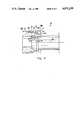
- FIG. 6is a longitudinal, sectional view of a tube and a first fitting member before tightening
- FIG. 7is a longitudinal, sectional view of the formed tube and a female first fitting member before tightening
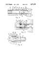
- FIG. 8is a longitudinal, sectional view of the assembled fitting members and tube.
- FIG. 9is a similar longitudinal, sectional view of assembled fitting members and tube with increased torque.
- the drawingsshow a tube fitting assembly 11 and the method of making this assembly, which includes generally, as shown in FIGS. 8 and 9, a tube 12 and first and second fitting members 13 and 14.
- the fitting members 13 and 14are interengageable, and in the preferred embodiment are each threaded one with a male thread and one with a female threaded for interthreading engagement.
- the first fitting member 13Amay have a male thread, as shown in FIGS. 1, 2, and 8, or may be a female thread fitting member 13B, as shown in FIGS. 7 and 9.
- the first fitting member 13may have any of the usual means for actuation by a tool, such as a hexagonal wrench pad 15 and, similarly, the second fitting member 14 also has provision for operation by a tool, again, as an example by the hexagonal wrench pad 16.
- first fitting member 13Ashown in FIGS. 1, 2, and 8
- male threads 17are provided on the first threading member 13 and a lead-on portion 18 is provided at the entrance end of this fitting, which may be cylindrical or generally cylindrical, to provide an axial alignment means to lead into the female threads 21 of this second fitting member 14A.
- This alignment meanssubstantially aligns the two fitting members 13 and 14 so that a power wrench may be used to tighten together the two fitting members without any preliminary manual threading of the first fitting member.
- the first fitting member 13Ahas a lateral shoulder 22A on the forward end thereof, and the second fitting member 14A has a lateral shoulder 23A.
- the second fitting member 14Amay be a standard fitting as used in the prior art, and as normally used with a separate sleeve or ferrule which has two conically tapered end portions and which encircles but is separate from the tube. Such ferrule might have two ends each at an angle of about 15 or 20 degrees relative to the axis of the tube, and it normally cooperates with the lateral shoulder 23A. Accordingly, the prior art lateral shoulder is typically at a 45-degree angle relative to the axis 24 of the tube.
- the second fitting member 14Aalso typically has a shoulder 25 as a stop for advancing movement of the tube 12.
- the nut 13BWhen the male and female threads are reversed in their position on the fitting members, as shown in FIGS. 7 and 9 relative to FIGS. 2, 6, and 8, the nut 13B has female threads 27 to engage male threads 28 on the second fitting member 14B.
- the generally cylindrical lead-on portion 18Bis provided on the nut 13B, as is the lateral first shoulder 22B.
- the second fitting member 14Bhas the lateral shoulder 23B, which is typically at a 45-degree angle relative to the tube axis 24, whereas the lateral shoulder 22B is preferably at about a 90-degree angle relative to this axis.
- FIGS. 8 and 9A tube fitting assembly 11 in FIGS. 8 and 9 is shown in the completely assembled condition.
- FIGS. 2 and 5show the tubing with a plurality of annular beads 31 and 32 prior to interconnecting the two fitting members 13 and 14, and
- FIGS. 6 and 7show the tubing with the two fitting members before tightening.
- the tube 12is provided with first and second deformed areas 35 and 36, respectively.
- the second deformed areais closest to the end 37 of the tube 12, i.e., it is outboard of the first deformed area 35. Both deformed areas are deformed outwardly and the first and second annular beads are a part of these deformed areas.
- a generally U-shaped, annular portion 38lies between and joins the annular beads and all of these deformed areas are formed from the wall of the tubing 12.
- a keeper bead 39is provided inboard of the first fitting member 13B in order to retain this fitting member in position near the end 37 of the tube 12. This keeper bead 39 establishes the first lateral shoulder 22B as being adjacent the first deformed area 35.
- This first deformed areais not necessarily but is preferably an annular outwardly deformed area, and the shoulder 22B is preferably an annular shoulder on the first fitting member 13B.
- FIG. 1illustrates the preferred method of forming the plurality of annular beads on the tube 12.
- thisis illustrated with the male type of first fitting member 13A.
- Clamping jaws 41 and 42have generally semicylindrical inner surfaces to grasp the outer periphery of the tube 12 at a predetermined location from the end 37 of the tube.
- the first fitting member 13Ais slipped over the end of the tube up to the face of the jaws 41 and 42.
- a die 43is used to provide an axial compressive force on the end of the tube. This die has a shoulder 44 to engage the end of the tube and a radial recess 45 adjacent the front face 46 of the die.
- a sizing punch 49is provided coaxially inside of the die 43, and has a nose portion 50 plus an enlarged portion 51.
- the sizing punch 49may slide within the die 43 to a limited extent.
- FIG. 3shows a main fluid cylinder 58 containing a main piston 59 actuating a hollow piston rod 60. Also a piggyback cylinder 61 contains a piston 62 to actuate an internal piston rod 63. FIG. 3 shows the internal piston rod 63 with provision to actuate the sizing die 49 in advancing and retracting movements.
- the main piston rod 60may connect to the die 43 for advance and retract movements of this die.
- the method of forming the tube fittingincludes advancing the sizing punch 49 by means of the piggyback piston 62 and the enlarged portion 51 sizes the tube 12 up to about the entrance of the first fitting member 13A, as shown in FIG. 1.
- Commercially produced tubinghas a range of inside and outside diameters, and therefore this sizing punch 49 creates a uniform diameter of the tubing for subsequent operations.
- the die 43is advanced by the main piston 49 until the front face of the die 46 is aligned with the end of the first fitting member 13A, FIG. 2.
- the die shoulder 44engages the end 37 of the tube and axially contracts a portion of the tube to create the plurality of deformed areas 35 and 36. This may be two or more, and two such deformed areas have been found to be a preferred structure.
- the tubeis configured as shown in FIGS. 2, 6, and 7, with the first and second deformed areas 35 and 36 which include the first and second annular beads 31 and 32, respectively.
- the U-shaped portion 38is provided at this time and, as shown in FIG.
- thisprovides four laterally directed portions of the tubing wall which are all spaced apart from one another, yet unitarily joined. Also, this axial contraction of the tube may be used to provide a keeper bead 39 to retain the first fitting member 13 in position.
- this keeper beadmay be established inboard of a keeper shoulder 64 near the front end or first shoulder 22A. This keeps the first fitting member 13A in position close to the end 37 of the tube.
- FIG. 4shows an alternative method of establishing the first and second deformed areas 35 and 36.
- No piggyback cylindersare used, but only a single cylinder and piston to move the sizing punch 49.
- Punch 49may slide within the die 43, as limited by a screw 52.
- the initial forward movement of the punch 49sizes the end of the tubing until the punch shoulder 54 is at the first shoulder 22A of member 13A. This is the condition shown in FIG. 4.
- Further advancing movement of die 43compresses a spring 53 in a cavity on the die 43, and the plural deformed areas 35 and 36 are formed as in FIG. 2.
- the tubeis now ready for insertion into the second fitting member 14A and initially interthreaded, as shown in FIG. 6.
- FIG. 5shows a still further method of establishing the first and second deformed areas 35 and 36.
- a central rod 68and is on the forward end of a sizing punch 69.
- a sizing head 70may slide on this central rod 68 and is retained thereon by a retaining ring 71.
- a plurality of die rubber washers 72 with separating shims 73is provided between the sizing head 70 and the sizing punch 69.
- the sizing punch 69is coaxially inside of a die 74.
- a single piston and cylinderwill move the sizing head 70 into the tube to slightly enlarge the tube to a uniform size.
- the die 74may be advanced further by the piston, and this will axially contract the tube so that the tubing wall forms a plurality of outwardly deformed areas.
- the die rubber washers 72will be axially compressed so as to radially expand and help form, in this case, the first and second deformed areas 35 and 36.
- the deformed areas 35 and 36are established with at least a second annular bead 32 extending at about a 60-degree angle relative to the axis 24.
- FIGS. 8 and 9show the tube fitting assembly 11 when the fitting members 13 and 14 have been interthreaded to exert a longitudinal compression force on the deformed areas 35 and 36.
- the lead-on portion 18helps to align the two fitting members to be substantially coaxial so that no cross-threading will occur, but instead a power wrench may be applied to the first fitting member 13A without any need to first hand-thread this fitting member into the second fitting member 14A. Also, only a small amount of rotation of the first fitting member 13A is required, e.g., one-and-a-half to two turns after the shoulder 22A engages the bead 31.
- first lateral shoulder 22engages the first deformed area 35 and move it towards the second lateral shoulder 23A on the second fitting member 14A.
- second annular bead 32engages the second lateral shoulder 23.
- the axial compressioncauses all four annular portions to be compressed into mutual engagement, i.e., each lateral portion is compressed so as to be contiguous to the next adjacent portion or portions.
- first shoulder 22Ais generally at right angles to the axis means that the first annular bead 31 is pushed axially and without much tendency to collapse radially inwardly.
- the second shoulder 23Abeing at about a 45-degree angle, establishes not only an axial component on the second annular bead 32, but also a radially inward compressive force so that this bead is forced somewhat inwardly relative to the first annular bead 31.
- FIG. 8shows the fitting assembly 11 with about a normal amount of torque applied by the interthreading of the fitting members 13 and 14. Accordingly, the end 37 of the tube may not be pressed against the shoulder 25 on the second fitting 14A. Nevertheless, the seal which will hold fluidtight pressure of 200 psi, for example, is established between the second shoulder 23 on the fitting 14A and the second annular bead 32.
- FIG. 9illustrates the other type of fitting with a female first fitting member 13B and male second fitting member 14B.
- the first and second deformed areas 35 and 36are still present, but in this case are shown as being compressed axially to a greater extent such that the end 37 of the tube engages the shoulder 25.
- Thismight be the condition with considerable overtorqueing of the two fitting members or, alternatively, the repeated disassembly and reassembly of the tube fitting assembly 11, each time tightening the two fitting members together a little tighter.
Landscapes
- Engineering & Computer Science (AREA)
- General Engineering & Computer Science (AREA)
- Mechanical Engineering (AREA)
- Joints With Pressure Members (AREA)
Abstract
Description
Claims (18)
Priority Applications (1)
| Application Number | Priority Date | Filing Date | Title |
|---|---|---|---|
| US07/185,849US4871199A (en) | 1988-04-25 | 1988-04-25 | Double bead tube fitting |
Applications Claiming Priority (1)
| Application Number | Priority Date | Filing Date | Title |
|---|---|---|---|
| US07/185,849US4871199A (en) | 1988-04-25 | 1988-04-25 | Double bead tube fitting |
Publications (1)
| Publication Number | Publication Date |
|---|---|
| US4871199Atrue US4871199A (en) | 1989-10-03 |
Family
ID=22682686
Family Applications (1)
| Application Number | Title | Priority Date | Filing Date |
|---|---|---|---|
| US07/185,849Expired - LifetimeUS4871199A (en) | 1988-04-25 | 1988-04-25 | Double bead tube fitting |
Country Status (1)
| Country | Link |
|---|---|
| US (1) | US4871199A (en) |
Cited By (69)
| Publication number | Priority date | Publication date | Assignee | Title |
|---|---|---|---|---|
| GB2288996A (en)* | 1994-05-07 | 1995-11-08 | Walterscheid Gmbh Jean | Pipe connection,and pipe therefore |
| DE19511063A1 (en)* | 1994-05-07 | 1995-11-09 | Walterscheid Gmbh Jean | Pipe with a connection section for a pipe connection and method for producing the same |
| FR2729204A1 (en)* | 1995-01-11 | 1996-07-12 | Universal Enterprises Inc | HIGH TEMPERATURE DOUBLE-MOLDED TUBE CONNECTION ARRANGEMENT |
| US5553602A (en)* | 1995-11-03 | 1996-09-10 | Universal Enterprises, Inc. | Heat-dissipating extender |
| DE19520099A1 (en)* | 1995-06-01 | 1997-01-02 | Parker Hannifin Gmbh | Pressure-tight positive locking pipeline joint |
| WO1998010227A1 (en)* | 1996-09-05 | 1998-03-12 | Universal Tubular Systems, Inc. | Burner box without manifold return |
| WO1998015766A1 (en)* | 1996-10-07 | 1998-04-16 | Universal Tubular Systems, Inc. | Conduit connector and method |
| US6030003A (en)* | 1998-02-06 | 2000-02-29 | Universal Tubular Systems, Inc. | Gas supply device |
| AT406453B (en)* | 1996-02-19 | 2000-05-25 | Vaillant Gmbh | METHOD FOR PRODUCING A TUBE WITH A BAND |
| FR2801522A1 (en)* | 1999-11-30 | 2001-06-01 | Parker Hannifin Sa | Pipe end deforming procedure for making joint uses matrix with face recess and die to expand tube into recess |
| US20030094277A1 (en)* | 1998-12-07 | 2003-05-22 | Shell Oil Co. | Expansion cone for radially expanding tubular members |
| US20030098162A1 (en)* | 1998-12-07 | 2003-05-29 | Shell Oil Company | Method of inserting a tubular member into a wellbore |
| US20030107217A1 (en)* | 1999-10-12 | 2003-06-12 | Shell Oil Co. | Sealant for expandable connection |
| US20030192358A1 (en)* | 1999-11-30 | 2003-10-16 | Parker Hannifin Sa | Method for deforming a tube near one of its ends and tool used in this method |
| WO2003102365A1 (en)* | 2002-05-29 | 2003-12-11 | Eventure Global Technology | System for radially expanding a tubular member |
| US6663146B1 (en)* | 1998-10-29 | 2003-12-16 | Toyota Jidosha Kabushiki Kaisha | Single flare tube and joint structure of single flare tube |
| US6857473B2 (en) | 1999-02-26 | 2005-02-22 | Shell Oil Company | Method of coupling a tubular member to a preexisting structure |
| US6877779B2 (en) | 1996-10-07 | 2005-04-12 | Universal Tubular Systems, Inc. | Conduit connector and method |
| US6968618B2 (en) | 1999-04-26 | 2005-11-29 | Shell Oil Company | Expandable connector |
| US6976541B2 (en) | 2000-09-18 | 2005-12-20 | Shell Oil Company | Liner hanger with sliding sleeve valve |
| US7021390B2 (en) | 1998-12-07 | 2006-04-04 | Shell Oil Company | Tubular liner for wellbore casing |
| US7048067B1 (en) | 1999-11-01 | 2006-05-23 | Shell Oil Company | Wellbore casing repair |
| US7055608B2 (en) | 1999-03-11 | 2006-06-06 | Shell Oil Company | Forming a wellbore casing while simultaneously drilling a wellbore |
| US7077211B2 (en) | 1998-12-07 | 2006-07-18 | Shell Oil Company | Method of creating a casing in a borehole |
| US7100684B2 (en) | 2000-07-28 | 2006-09-05 | Enventure Global Technology | Liner hanger with standoffs |
| US7100685B2 (en) | 2000-10-02 | 2006-09-05 | Enventure Global Technology | Mono-diameter wellbore casing |
| US7147053B2 (en) | 1998-12-07 | 2006-12-12 | Shell Oil Company | Wellhead |
| US20070003394A1 (en)* | 2005-02-01 | 2007-01-04 | Carey Paul G | Anti-cross threading fastener |
| US7168499B2 (en) | 1998-11-16 | 2007-01-30 | Shell Oil Company | Radial expansion of tubular members |
| US7168496B2 (en) | 2001-07-06 | 2007-01-30 | Eventure Global Technology | Liner hanger |
| US7172024B2 (en) | 2000-10-02 | 2007-02-06 | Shell Oil Company | Mono-diameter wellbore casing |
| US7185710B2 (en) | 1998-12-07 | 2007-03-06 | Enventure Global Technology | Mono-diameter wellbore casing |
| US7195064B2 (en) | 1998-12-07 | 2007-03-27 | Enventure Global Technology | Mono-diameter wellbore casing |
| US7231985B2 (en) | 1998-11-16 | 2007-06-19 | Shell Oil Company | Radial expansion of tubular members |
| US7234531B2 (en) | 1999-12-03 | 2007-06-26 | Enventure Global Technology, Llc | Mono-diameter wellbore casing |
| US7240728B2 (en) | 1998-12-07 | 2007-07-10 | Shell Oil Company | Expandable tubulars with a radial passage and wall portions with different wall thicknesses |
| US7258168B2 (en) | 2001-07-27 | 2007-08-21 | Enventure Global Technology L.L.C. | Liner hanger with slip joint sealing members and method of use |
| US7290605B2 (en) | 2001-12-27 | 2007-11-06 | Enventure Global Technology | Seal receptacle using expandable liner hanger |
| US7290616B2 (en) | 2001-07-06 | 2007-11-06 | Enventure Global Technology, L.L.C. | Liner hanger |
| US7308755B2 (en) | 2003-06-13 | 2007-12-18 | Shell Oil Company | Apparatus for forming a mono-diameter wellbore casing |
| US7325602B2 (en) | 2000-10-02 | 2008-02-05 | Shell Oil Company | Method and apparatus for forming a mono-diameter wellbore casing |
| US7350563B2 (en) | 1999-07-09 | 2008-04-01 | Enventure Global Technology, L.L.C. | System for lining a wellbore casing |
| US7363984B2 (en) | 1998-12-07 | 2008-04-29 | Enventure Global Technology, Llc | System for radially expanding a tubular member |
| US7377326B2 (en) | 2002-08-23 | 2008-05-27 | Enventure Global Technology, L.L.C. | Magnetic impulse applied sleeve method of forming a wellbore casing |
| US7383889B2 (en) | 2001-11-12 | 2008-06-10 | Enventure Global Technology, Llc | Mono diameter wellbore casing |
| US7398832B2 (en) | 2002-06-10 | 2008-07-15 | Enventure Global Technology, Llc | Mono-diameter wellbore casing |
| US7404444B2 (en) | 2002-09-20 | 2008-07-29 | Enventure Global Technology | Protective sleeve for expandable tubulars |
| US7410000B2 (en) | 2001-01-17 | 2008-08-12 | Enventure Global Technology, Llc. | Mono-diameter wellbore casing |
| US7416027B2 (en) | 2001-09-07 | 2008-08-26 | Enventure Global Technology, Llc | Adjustable expansion cone assembly |
| US7424918B2 (en) | 2002-08-23 | 2008-09-16 | Enventure Global Technology, L.L.C. | Interposed joint sealing layer method of forming a wellbore casing |
| US7438133B2 (en) | 2003-02-26 | 2008-10-21 | Enventure Global Technology, Llc | Apparatus and method for radially expanding and plastically deforming a tubular member |
| US7503393B2 (en) | 2003-01-27 | 2009-03-17 | Enventure Global Technology, Inc. | Lubrication system for radially expanding tubular members |
| US7513313B2 (en) | 2002-09-20 | 2009-04-07 | Enventure Global Technology, Llc | Bottom plug for forming a mono diameter wellbore casing |
| US7516790B2 (en) | 1999-12-03 | 2009-04-14 | Enventure Global Technology, Llc | Mono-diameter wellbore casing |
| US7552776B2 (en) | 1998-12-07 | 2009-06-30 | Enventure Global Technology, Llc | Anchor hangers |
| US7571774B2 (en) | 2002-09-20 | 2009-08-11 | Eventure Global Technology | Self-lubricating expansion mandrel for expandable tubular |
| US7603758B2 (en) | 1998-12-07 | 2009-10-20 | Shell Oil Company | Method of coupling a tubular member |
| US7712522B2 (en) | 2003-09-05 | 2010-05-11 | Enventure Global Technology, Llc | Expansion cone and system |
| US7740076B2 (en) | 2002-04-12 | 2010-06-22 | Enventure Global Technology, L.L.C. | Protective sleeve for threaded connections for expandable liner hanger |
| US7739917B2 (en) | 2002-09-20 | 2010-06-22 | Enventure Global Technology, Llc | Pipe formability evaluation for expandable tubulars |
| US7775290B2 (en) | 2003-04-17 | 2010-08-17 | Enventure Global Technology, Llc | Apparatus for radially expanding and plastically deforming a tubular member |
| US7793721B2 (en) | 2003-03-11 | 2010-09-14 | Eventure Global Technology, Llc | Apparatus for radially expanding and plastically deforming a tubular member |
| US7819185B2 (en) | 2004-08-13 | 2010-10-26 | Enventure Global Technology, Llc | Expandable tubular |
| US7886831B2 (en) | 2003-01-22 | 2011-02-15 | Enventure Global Technology, L.L.C. | Apparatus for radially expanding and plastically deforming a tubular member |
| US7918284B2 (en) | 2002-04-15 | 2011-04-05 | Enventure Global Technology, L.L.C. | Protective sleeve for threaded connections for expandable liner hanger |
| US8079621B2 (en) | 2007-11-15 | 2011-12-20 | Lincoln Brass Works, Inc. | Reinforced bead tube design |
| US20120056422A1 (en)* | 2010-09-08 | 2012-03-08 | GM Global Technology Operations LLC | Pipe connection for connecting pipes of a motor vehicle, exhaust system, air intake system and motor vehicle |
| US8832922B1 (en)* | 2011-09-13 | 2014-09-16 | Burner Systems International, Inc. | Connection and elbow in a gas appliance |
| US9464812B2 (en) | 2012-10-29 | 2016-10-11 | Whirlpool Corporation | Gas supply module for burner with beaded gas supply tube |
Citations (16)
| Publication number | Priority date | Publication date | Assignee | Title |
|---|---|---|---|---|
| US1733925A (en)* | 1928-12-03 | 1929-10-29 | Jr Albert J Weatherhead | Pipe coupling |
| US1961453A (en)* | 1932-05-25 | 1934-06-05 | Bundy Tubing Co | Tube coupling |
| US2522195A (en)* | 1947-01-18 | 1950-09-12 | Brockway Company | Pipe connection |
| US2634786A (en)* | 1947-12-13 | 1953-04-14 | H B Sherman Mfg Company | Method of mounting separable thin metal nipple hose couplings |
| US2779279A (en)* | 1952-03-08 | 1957-01-29 | Paul S Maiwurm | Apparatus for securing a tube or tubes in a body member |
| US3092404A (en)* | 1961-01-25 | 1963-06-04 | Macwilliam Wallace | Packed screw threaded gland type tube coupling for thin walled tubing |
| US3195936A (en)* | 1962-12-17 | 1965-07-20 | Alfred C Conder | Special sleeve and coupling b-nuts |
| US3665591A (en)* | 1970-01-02 | 1972-05-30 | Imp Eastman Corp | Method of making up an expandable insert fitting |
| US3715800A (en)* | 1969-12-16 | 1973-02-13 | Mueller Co | Method of making a coupling joint |
| US3730567A (en)* | 1970-07-08 | 1973-05-01 | Axial Corp | Coupling sleeve |
| US3765708A (en)* | 1971-11-08 | 1973-10-16 | Boeing Co | Tubing union |
| US3778090A (en)* | 1972-05-18 | 1973-12-11 | Gen Motors Corp | Beaded tube with o-ring seal connection |
| US3817562A (en)* | 1972-07-14 | 1974-06-18 | Numatics Inc | Connector for plastic tube |
| US4240774A (en)* | 1979-02-15 | 1980-12-23 | General Electric Company | Hermetically sealed compressor suction tube and method of assembly |
| US4575134A (en)* | 1983-06-15 | 1986-03-11 | Nihon Radiator Co., Ltd. | Pipe joint construction |
| US4682832A (en)* | 1985-09-27 | 1987-07-28 | Allied Corporation | Retaining an insert in an electrical connector |
- 1988
- 1988-04-25USUS07/185,849patent/US4871199A/ennot_activeExpired - Lifetime
Patent Citations (16)
| Publication number | Priority date | Publication date | Assignee | Title |
|---|---|---|---|---|
| US1733925A (en)* | 1928-12-03 | 1929-10-29 | Jr Albert J Weatherhead | Pipe coupling |
| US1961453A (en)* | 1932-05-25 | 1934-06-05 | Bundy Tubing Co | Tube coupling |
| US2522195A (en)* | 1947-01-18 | 1950-09-12 | Brockway Company | Pipe connection |
| US2634786A (en)* | 1947-12-13 | 1953-04-14 | H B Sherman Mfg Company | Method of mounting separable thin metal nipple hose couplings |
| US2779279A (en)* | 1952-03-08 | 1957-01-29 | Paul S Maiwurm | Apparatus for securing a tube or tubes in a body member |
| US3092404A (en)* | 1961-01-25 | 1963-06-04 | Macwilliam Wallace | Packed screw threaded gland type tube coupling for thin walled tubing |
| US3195936A (en)* | 1962-12-17 | 1965-07-20 | Alfred C Conder | Special sleeve and coupling b-nuts |
| US3715800A (en)* | 1969-12-16 | 1973-02-13 | Mueller Co | Method of making a coupling joint |
| US3665591A (en)* | 1970-01-02 | 1972-05-30 | Imp Eastman Corp | Method of making up an expandable insert fitting |
| US3730567A (en)* | 1970-07-08 | 1973-05-01 | Axial Corp | Coupling sleeve |
| US3765708A (en)* | 1971-11-08 | 1973-10-16 | Boeing Co | Tubing union |
| US3778090A (en)* | 1972-05-18 | 1973-12-11 | Gen Motors Corp | Beaded tube with o-ring seal connection |
| US3817562A (en)* | 1972-07-14 | 1974-06-18 | Numatics Inc | Connector for plastic tube |
| US4240774A (en)* | 1979-02-15 | 1980-12-23 | General Electric Company | Hermetically sealed compressor suction tube and method of assembly |
| US4575134A (en)* | 1983-06-15 | 1986-03-11 | Nihon Radiator Co., Ltd. | Pipe joint construction |
| US4682832A (en)* | 1985-09-27 | 1987-07-28 | Allied Corporation | Retaining an insert in an electrical connector |
Cited By (121)
| Publication number | Priority date | Publication date | Assignee | Title |
|---|---|---|---|---|
| DE19511063C2 (en)* | 1994-05-07 | 2000-01-13 | Walterscheid Gmbh Jean | Pipe connection with a pipe with a connecting section and method for producing the same |
| DE19511063A1 (en)* | 1994-05-07 | 1995-11-09 | Walterscheid Gmbh Jean | Pipe with a connection section for a pipe connection and method for producing the same |
| GB2288996B (en)* | 1994-05-07 | 1997-01-08 | Walterscheid Gmbh Jean | Pipe connection, and pipe therefor |
| GB2288996A (en)* | 1994-05-07 | 1995-11-08 | Walterscheid Gmbh Jean | Pipe connection,and pipe therefore |
| FR2729204A1 (en)* | 1995-01-11 | 1996-07-12 | Universal Enterprises Inc | HIGH TEMPERATURE DOUBLE-MOLDED TUBE CONNECTION ARRANGEMENT |
| US5573285A (en)* | 1995-01-11 | 1996-11-12 | Universal Enterprises, Inc. | High-temperature, double-bead, tube-fitting assembly |
| DE19520099A1 (en)* | 1995-06-01 | 1997-01-02 | Parker Hannifin Gmbh | Pressure-tight positive locking pipeline joint |
| DE19520099C3 (en)* | 1995-06-01 | 2002-05-29 | Walterscheid Gmbh Jean | Pipe connection and process for its manufacture |
| DE19520099C2 (en)* | 1995-06-01 | 1999-09-30 | Parker Hannifin Gmbh | Pipe connection and process for its manufacture |
| US5553602A (en)* | 1995-11-03 | 1996-09-10 | Universal Enterprises, Inc. | Heat-dissipating extender |
| WO1997016681A1 (en)* | 1995-11-03 | 1997-05-09 | Universal Enterprises, Inc. | Heat-dissipating extender |
| AT406453B (en)* | 1996-02-19 | 2000-05-25 | Vaillant Gmbh | METHOD FOR PRODUCING A TUBE WITH A BAND |
| US5851110A (en)* | 1996-09-05 | 1998-12-22 | Universal Tubular Systems, Inc. | Burner box without manifold return |
| US6068471A (en)* | 1996-09-05 | 2000-05-30 | Universal Tubular Systems, Inc. | Burner box without manifold return |
| WO1998010227A1 (en)* | 1996-09-05 | 1998-03-12 | Universal Tubular Systems, Inc. | Burner box without manifold return |
| US6575502B1 (en) | 1996-10-07 | 2003-06-10 | Universal Tubular Systems Inc. | Conduit connector and method |
| US6170888B1 (en) | 1996-10-07 | 2001-01-09 | Universal Tubular Systems, Inc. | Conduit connector and method |
| US6877779B2 (en) | 1996-10-07 | 2005-04-12 | Universal Tubular Systems, Inc. | Conduit connector and method |
| WO1998015766A1 (en)* | 1996-10-07 | 1998-04-16 | Universal Tubular Systems, Inc. | Conduit connector and method |
| US6030003A (en)* | 1998-02-06 | 2000-02-29 | Universal Tubular Systems, Inc. | Gas supply device |
| US6219917B1 (en) | 1998-02-06 | 2001-04-24 | Universal Tubular Systems, Inc. | Gas supply device |
| US6663146B1 (en)* | 1998-10-29 | 2003-12-16 | Toyota Jidosha Kabushiki Kaisha | Single flare tube and joint structure of single flare tube |
| US7357190B2 (en) | 1998-11-16 | 2008-04-15 | Shell Oil Company | Radial expansion of tubular members |
| US7168499B2 (en) | 1998-11-16 | 2007-01-30 | Shell Oil Company | Radial expansion of tubular members |
| US7231985B2 (en) | 1998-11-16 | 2007-06-19 | Shell Oil Company | Radial expansion of tubular members |
| US7246667B2 (en) | 1998-11-16 | 2007-07-24 | Shell Oil Company | Radial expansion of tubular members |
| US7270188B2 (en) | 1998-11-16 | 2007-09-18 | Shell Oil Company | Radial expansion of tubular members |
| US7275601B2 (en) | 1998-11-16 | 2007-10-02 | Shell Oil Company | Radial expansion of tubular members |
| US7299881B2 (en) | 1998-11-16 | 2007-11-27 | Shell Oil Company | Radial expansion of tubular members |
| US7665532B2 (en) | 1998-12-07 | 2010-02-23 | Shell Oil Company | Pipeline |
| US7086475B2 (en) | 1998-12-07 | 2006-08-08 | Shell Oil Company | Method of inserting a tubular member into a wellbore |
| US20030098162A1 (en)* | 1998-12-07 | 2003-05-29 | Shell Oil Company | Method of inserting a tubular member into a wellbore |
| US7603758B2 (en) | 1998-12-07 | 2009-10-20 | Shell Oil Company | Method of coupling a tubular member |
| US7350564B2 (en) | 1998-12-07 | 2008-04-01 | Enventure Global Technology, L.L.C. | Mono-diameter wellbore casing |
| US7011161B2 (en) | 1998-12-07 | 2006-03-14 | Shell Oil Company | Structural support |
| US7021390B2 (en) | 1998-12-07 | 2006-04-04 | Shell Oil Company | Tubular liner for wellbore casing |
| US7036582B2 (en) | 1998-12-07 | 2006-05-02 | Shell Oil Company | Expansion cone for radially expanding tubular members |
| US7363984B2 (en) | 1998-12-07 | 2008-04-29 | Enventure Global Technology, Llc | System for radially expanding a tubular member |
| US7044218B2 (en) | 1998-12-07 | 2006-05-16 | Shell Oil Company | Apparatus for radially expanding tubular members |
| US7174964B2 (en) | 1998-12-07 | 2007-02-13 | Shell Oil Company | Wellhead with radially expanded tubulars |
| US7048062B2 (en) | 1998-12-07 | 2006-05-23 | Shell Oil Company | Method of selecting tubular members |
| US7419009B2 (en) | 1998-12-07 | 2008-09-02 | Shell Oil Company | Apparatus for radially expanding and plastically deforming a tubular member |
| US7077213B2 (en) | 1998-12-07 | 2006-07-18 | Shell Oil Company | Expansion cone for radially expanding tubular members |
| US7077211B2 (en) | 1998-12-07 | 2006-07-18 | Shell Oil Company | Method of creating a casing in a borehole |
| US7357188B1 (en) | 1998-12-07 | 2008-04-15 | Shell Oil Company | Mono-diameter wellbore casing |
| US7434618B2 (en) | 1998-12-07 | 2008-10-14 | Shell Oil Company | Apparatus for expanding a tubular member |
| US7240729B2 (en) | 1998-12-07 | 2007-07-10 | Shell Oil Company | Apparatus for expanding a tubular member |
| US7121337B2 (en) | 1998-12-07 | 2006-10-17 | Shell Oil Company | Apparatus for expanding a tubular member |
| US7240728B2 (en) | 1998-12-07 | 2007-07-10 | Shell Oil Company | Expandable tubulars with a radial passage and wall portions with different wall thicknesses |
| US7552776B2 (en) | 1998-12-07 | 2009-06-30 | Enventure Global Technology, Llc | Anchor hangers |
| US7147053B2 (en) | 1998-12-07 | 2006-12-12 | Shell Oil Company | Wellhead |
| US7216701B2 (en) | 1998-12-07 | 2007-05-15 | Shell Oil Company | Apparatus for expanding a tubular member |
| US7198100B2 (en) | 1998-12-07 | 2007-04-03 | Shell Oil Company | Apparatus for expanding a tubular member |
| US7185710B2 (en) | 1998-12-07 | 2007-03-06 | Enventure Global Technology | Mono-diameter wellbore casing |
| US20030094277A1 (en)* | 1998-12-07 | 2003-05-22 | Shell Oil Co. | Expansion cone for radially expanding tubular members |
| US7195064B2 (en) | 1998-12-07 | 2007-03-27 | Enventure Global Technology | Mono-diameter wellbore casing |
| US7195061B2 (en) | 1998-12-07 | 2007-03-27 | Shell Oil Company | Apparatus for expanding a tubular member |
| US7159667B2 (en) | 1999-02-25 | 2007-01-09 | Shell Oil Company | Method of coupling a tubular member to a preexisting structure |
| US6857473B2 (en) | 1999-02-26 | 2005-02-22 | Shell Oil Company | Method of coupling a tubular member to a preexisting structure |
| US7556092B2 (en) | 1999-02-26 | 2009-07-07 | Enventure Global Technology, Llc | Flow control system for an apparatus for radially expanding tubular members |
| US7044221B2 (en) | 1999-02-26 | 2006-05-16 | Shell Oil Company | Apparatus for coupling a tubular member to a preexisting structure |
| US7055608B2 (en) | 1999-03-11 | 2006-06-06 | Shell Oil Company | Forming a wellbore casing while simultaneously drilling a wellbore |
| US7438132B2 (en) | 1999-03-11 | 2008-10-21 | Shell Oil Company | Concentric pipes expanded at the pipe ends and method of forming |
| US6968618B2 (en) | 1999-04-26 | 2005-11-29 | Shell Oil Company | Expandable connector |
| US7350563B2 (en) | 1999-07-09 | 2008-04-01 | Enventure Global Technology, L.L.C. | System for lining a wellbore casing |
| US20030107217A1 (en)* | 1999-10-12 | 2003-06-12 | Shell Oil Co. | Sealant for expandable connection |
| US7048067B1 (en) | 1999-11-01 | 2006-05-23 | Shell Oil Company | Wellbore casing repair |
| US6792782B2 (en) | 1999-11-30 | 2004-09-21 | Parker Hannifin Sa | Method for deforming a tube near one of its ends and tool used in this method |
| FR2801522A1 (en)* | 1999-11-30 | 2001-06-01 | Parker Hannifin Sa | Pipe end deforming procedure for making joint uses matrix with face recess and die to expand tube into recess |
| US20030192358A1 (en)* | 1999-11-30 | 2003-10-16 | Parker Hannifin Sa | Method for deforming a tube near one of its ends and tool used in this method |
| WO2001039907A1 (en)* | 1999-11-30 | 2001-06-07 | Parker Hannifin Sa | Method for deforming a tube in the proximity of one of its ends and tool therefor |
| US7234531B2 (en) | 1999-12-03 | 2007-06-26 | Enventure Global Technology, Llc | Mono-diameter wellbore casing |
| US7516790B2 (en) | 1999-12-03 | 2009-04-14 | Enventure Global Technology, Llc | Mono-diameter wellbore casing |
| US7100684B2 (en) | 2000-07-28 | 2006-09-05 | Enventure Global Technology | Liner hanger with standoffs |
| US6976541B2 (en) | 2000-09-18 | 2005-12-20 | Shell Oil Company | Liner hanger with sliding sleeve valve |
| US7172021B2 (en) | 2000-09-18 | 2007-02-06 | Shell Oil Company | Liner hanger with sliding sleeve valve |
| US7201223B2 (en) | 2000-10-02 | 2007-04-10 | Shell Oil Company | Method and apparatus for forming a mono-diameter wellbore casing |
| US7204007B2 (en) | 2000-10-02 | 2007-04-17 | Shell Oil Company | Method and apparatus for forming a mono-diameter wellbore casing |
| US7172019B2 (en) | 2000-10-02 | 2007-02-06 | Shell Oil Company | Method and apparatus for forming a mono-diameter wellbore casing |
| US7325602B2 (en) | 2000-10-02 | 2008-02-05 | Shell Oil Company | Method and apparatus for forming a mono-diameter wellbore casing |
| US7172024B2 (en) | 2000-10-02 | 2007-02-06 | Shell Oil Company | Mono-diameter wellbore casing |
| US7100685B2 (en) | 2000-10-02 | 2006-09-05 | Enventure Global Technology | Mono-diameter wellbore casing |
| US7363690B2 (en) | 2000-10-02 | 2008-04-29 | Shell Oil Company | Method and apparatus for forming a mono-diameter wellbore casing |
| US7363691B2 (en) | 2000-10-02 | 2008-04-29 | Shell Oil Company | Method and apparatus for forming a mono-diameter wellbore casing |
| US7146702B2 (en) | 2000-10-02 | 2006-12-12 | Shell Oil Company | Method and apparatus for forming a mono-diameter wellbore casing |
| US7410000B2 (en) | 2001-01-17 | 2008-08-12 | Enventure Global Technology, Llc. | Mono-diameter wellbore casing |
| US7290616B2 (en) | 2001-07-06 | 2007-11-06 | Enventure Global Technology, L.L.C. | Liner hanger |
| US7168496B2 (en) | 2001-07-06 | 2007-01-30 | Eventure Global Technology | Liner hanger |
| US7258168B2 (en) | 2001-07-27 | 2007-08-21 | Enventure Global Technology L.L.C. | Liner hanger with slip joint sealing members and method of use |
| US7416027B2 (en) | 2001-09-07 | 2008-08-26 | Enventure Global Technology, Llc | Adjustable expansion cone assembly |
| US7383889B2 (en) | 2001-11-12 | 2008-06-10 | Enventure Global Technology, Llc | Mono diameter wellbore casing |
| US7559365B2 (en) | 2001-11-12 | 2009-07-14 | Enventure Global Technology, Llc | Collapsible expansion cone |
| US7290605B2 (en) | 2001-12-27 | 2007-11-06 | Enventure Global Technology | Seal receptacle using expandable liner hanger |
| US7740076B2 (en) | 2002-04-12 | 2010-06-22 | Enventure Global Technology, L.L.C. | Protective sleeve for threaded connections for expandable liner hanger |
| US7918284B2 (en) | 2002-04-15 | 2011-04-05 | Enventure Global Technology, L.L.C. | Protective sleeve for threaded connections for expandable liner hanger |
| US7360591B2 (en) | 2002-05-29 | 2008-04-22 | Enventure Global Technology, Llc | System for radially expanding a tubular member |
| GB2406125B (en)* | 2002-05-29 | 2006-11-01 | Enventure Global Technology | Radially expanding a tubular member |
| WO2003102365A1 (en)* | 2002-05-29 | 2003-12-11 | Eventure Global Technology | System for radially expanding a tubular member |
| GB2406125A (en)* | 2002-05-29 | 2005-03-23 | Enventure Global Technology | System for radially expanding a tubular member |
| GB2426993B (en)* | 2002-05-29 | 2007-05-02 | Enventure Global Technology | System for radially expanding a tubular member |
| GB2426993A (en)* | 2002-05-29 | 2006-12-13 | Enventure Global Technology | Tubular expander with compressible elastomeric member |
| US7398832B2 (en) | 2002-06-10 | 2008-07-15 | Enventure Global Technology, Llc | Mono-diameter wellbore casing |
| US7424918B2 (en) | 2002-08-23 | 2008-09-16 | Enventure Global Technology, L.L.C. | Interposed joint sealing layer method of forming a wellbore casing |
| US7377326B2 (en) | 2002-08-23 | 2008-05-27 | Enventure Global Technology, L.L.C. | Magnetic impulse applied sleeve method of forming a wellbore casing |
| US7404444B2 (en) | 2002-09-20 | 2008-07-29 | Enventure Global Technology | Protective sleeve for expandable tubulars |
| US7513313B2 (en) | 2002-09-20 | 2009-04-07 | Enventure Global Technology, Llc | Bottom plug for forming a mono diameter wellbore casing |
| US7571774B2 (en) | 2002-09-20 | 2009-08-11 | Eventure Global Technology | Self-lubricating expansion mandrel for expandable tubular |
| US7739917B2 (en) | 2002-09-20 | 2010-06-22 | Enventure Global Technology, Llc | Pipe formability evaluation for expandable tubulars |
| US7886831B2 (en) | 2003-01-22 | 2011-02-15 | Enventure Global Technology, L.L.C. | Apparatus for radially expanding and plastically deforming a tubular member |
| US7503393B2 (en) | 2003-01-27 | 2009-03-17 | Enventure Global Technology, Inc. | Lubrication system for radially expanding tubular members |
| US7438133B2 (en) | 2003-02-26 | 2008-10-21 | Enventure Global Technology, Llc | Apparatus and method for radially expanding and plastically deforming a tubular member |
| US7793721B2 (en) | 2003-03-11 | 2010-09-14 | Eventure Global Technology, Llc | Apparatus for radially expanding and plastically deforming a tubular member |
| US7775290B2 (en) | 2003-04-17 | 2010-08-17 | Enventure Global Technology, Llc | Apparatus for radially expanding and plastically deforming a tubular member |
| US7308755B2 (en) | 2003-06-13 | 2007-12-18 | Shell Oil Company | Apparatus for forming a mono-diameter wellbore casing |
| US7712522B2 (en) | 2003-09-05 | 2010-05-11 | Enventure Global Technology, Llc | Expansion cone and system |
| US7819185B2 (en) | 2004-08-13 | 2010-10-26 | Enventure Global Technology, Llc | Expandable tubular |
| US20070003394A1 (en)* | 2005-02-01 | 2007-01-04 | Carey Paul G | Anti-cross threading fastener |
| US8079621B2 (en) | 2007-11-15 | 2011-12-20 | Lincoln Brass Works, Inc. | Reinforced bead tube design |
| US20120056422A1 (en)* | 2010-09-08 | 2012-03-08 | GM Global Technology Operations LLC | Pipe connection for connecting pipes of a motor vehicle, exhaust system, air intake system and motor vehicle |
| US8832922B1 (en)* | 2011-09-13 | 2014-09-16 | Burner Systems International, Inc. | Connection and elbow in a gas appliance |
| US9464812B2 (en) | 2012-10-29 | 2016-10-11 | Whirlpool Corporation | Gas supply module for burner with beaded gas supply tube |
Similar Documents
| Publication | Publication Date | Title |
|---|---|---|
| US4871199A (en) | Double bead tube fitting | |
| US3092404A (en) | Packed screw threaded gland type tube coupling for thin walled tubing | |
| US2464416A (en) | Hose end assembly | |
| US4674775A (en) | Coupling for corrugated conduit | |
| US4458926A (en) | Hydraulic hose adapter with O-ring seal | |
| US2452275A (en) | Tube fitting coupling | |
| US4736969A (en) | Fitting assembly for reinforced hose | |
| US3467413A (en) | Triple-sealing pipe joint | |
| US2021745A (en) | Threaded follower pipe joint or fitting | |
| US4664427A (en) | Quick connect fitting | |
| CN106461136B (en) | High pressure large inner diameter hose coupled with termination attachment | |
| US4412693A (en) | Swivel hose coupling with threaded nipple | |
| US3245701A (en) | Transition fitting | |
| US3120969A (en) | Flareless tube coupling | |
| TWI616609B (en) | Pipe connection | |
| US3501171A (en) | Connector assembly for fluid conduits | |
| US2197450A (en) | Pipe coupling | |
| US3074748A (en) | Threaded pipe connection | |
| US4691944A (en) | Tubing connector | |
| US3379461A (en) | Tube connector | |
| US2452276A (en) | Tube fitting device | |
| US11493156B2 (en) | Hammerless and torqueless union connection | |
| US2960353A (en) | Fluid threa sealing connection | |
| CA2147717C (en) | Tube fitting and assembly method | |
| US3765708A (en) | Tubing union |
Legal Events
| Date | Code | Title | Description |
|---|---|---|---|
| FEPP | Fee payment procedure | Free format text:PAYOR NUMBER ASSIGNED (ORIGINAL EVENT CODE: ASPN); ENTITY STATUS OF PATENT OWNER: LARGE ENTITY | |
| AS | Assignment | Owner name:UNIVERSAL ENTERPRISES, INC., A CORP. OF OH Free format text:ASSIGNMENT OF ASSIGNORS INTEREST.;ASSIGNORS:RIDENOUR, RALPH G.;STANTON, THOMAS;REEL/FRAME:005125/0166 Effective date:19890607 | |
| STCF | Information on status: patent grant | Free format text:PATENTED CASE | |
| FEPP | Fee payment procedure | Free format text:PAT HLDR NO LONGER CLAIMS SMALL ENT STAT AS SMALL BUSINESS (ORIGINAL EVENT CODE: LSM2); ENTITY STATUS OF PATENT OWNER: LARGE ENTITY | |
| FPAY | Fee payment | Year of fee payment:4 | |
| FEPP | Fee payment procedure | Free format text:PAT HOLDER CLAIMS SMALL ENTITY STATUS - SMALL BUSINESS (ORIGINAL EVENT CODE: SM02); ENTITY STATUS OF PATENT OWNER: LARGE ENTITY | |
| FPAY | Fee payment | Year of fee payment:8 | |
| AS | Assignment | Owner name:UNIVERSAL TUBULAR SYSTEMS, INC., OHIO Free format text:ASSIGNMENT OF ASSIGNORS INTEREST;ASSIGNOR:UNIVERSAL ENTERPRISES, INC.;REEL/FRAME:008447/0725 Effective date:19970404 | |
| FEPP | Fee payment procedure | Free format text:PAT HLDR NO LONGER CLAIMS SMALL ENT STAT AS SMALL BUSINESS (ORIGINAL EVENT CODE: LSM2); ENTITY STATUS OF PATENT OWNER: LARGE ENTITY | |
| FPAY | Fee payment | Year of fee payment:12 | |
| AS | Assignment | Owner name:JPMORGAN CHASE BANK, A NEW YORK BANKING CORPORATIO Free format text:ASSIGNMENT OF ASSIGNORS INTEREST;ASSIGNOR:UNIVERSAL TUBULAR SYSTEMS, INC.;REEL/FRAME:013305/0417 Effective date:20020628 | |
| AS | Assignment | Owner name:UNIVERSAL TUBULAR SYSTEMS, INC., TENNESSEE Free format text:TERMINATION OF SECURITY INTEREST;ASSIGNOR:JPMORGAN CHASE BANK, N.A.;REEL/FRAME:016460/0785 Effective date:20040824 Owner name:JPMORGAN CHASE BANK, N.A., NEW YORK Free format text:SECURITY AGREEMENT;ASSIGNOR:UNIVERSAL TUBULAR SYSTEMS, INC.;REEL/FRAME:016460/0798 Effective date:20050824 | |
| AS | Assignment | Owner name:BURNER SYSTEMS INTERNATIONAL INC., TENNESSEE Free format text:ASSIGNMENT OF ASSIGNORS INTEREST;ASSIGNOR:UNIVERSAL TUBULAR SYSTEMS, INC.;REEL/FRAME:017681/0658 Effective date:20050731 Owner name:BURNER SYSTEMS INTERNATIONAL, INC., TENNESSEE Free format text:ASSIGNMENT OF ASSIGNORS INTEREST;ASSIGNOR:UNIVERSAL TUBULAR SYSTEMS, INC.;REEL/FRAME:017681/0658 Effective date:20050731 | |
| FEPP | Fee payment procedure | Free format text:PAYER NUMBER DE-ASSIGNED (ORIGINAL EVENT CODE: RMPN); ENTITY STATUS OF PATENT OWNER: LARGE ENTITY Free format text:PAYOR NUMBER ASSIGNED (ORIGINAL EVENT CODE: ASPN); ENTITY STATUS OF PATENT OWNER: LARGE ENTITY | |
| AS | Assignment | Owner name:BURNER SYSTEMS INTERNATIONAL, INC., TENNESSEE Free format text:RELEASE OF SECURITY INTEREST IN PATENTS;ASSIGNOR:JPMORGAN CHASE BANK, N.A.;REEL/FRAME:028260/0202 Effective date:20120523 Owner name:UNIVERSAL TUBULAR SYSTEMS, INC., TENNESSEE Free format text:RELEASE OF SECURITY INTEREST IN PATENTS;ASSIGNOR:JPMORGAN CHASE BANK, N.A.;REEL/FRAME:028260/0202 Effective date:20120523 |