US4870970A - Ultrasonic investigation apparatus - Google Patents
Ultrasonic investigation apparatusDownload PDFInfo
- Publication number
- US4870970A US4870970AUS07/190,689US19068988AUS4870970AUS 4870970 AUS4870970 AUS 4870970AUS 19068988 AUS19068988 AUS 19068988AUS 4870970 AUS4870970 AUS 4870970A
- Authority
- US
- United States
- Prior art keywords
- well
- transducer
- housing
- membrane
- wall
- Prior art date
- Legal status (The legal status is an assumption and is not a legal conclusion. Google has not performed a legal analysis and makes no representation as to the accuracy of the status listed.)
- Expired - Fee Related
Links
- 238000011835investigationMethods0.000titledescription13
- 239000012530fluidSubstances0.000claimsabstractdescription19
- XLYOFNOQVPJJNP-UHFFFAOYSA-NwaterSubstancesOXLYOFNOQVPJJNP-UHFFFAOYSA-N0.000claimsabstractdescription16
- 238000002592echocardiographyMethods0.000claimsabstractdescription8
- 239000012528membraneSubstances0.000claimsdescription24
- 238000007789sealingMethods0.000claimsdescription13
- 210000003491skinAnatomy0.000description17
- 238000000034methodMethods0.000description6
- 230000008878couplingEffects0.000description4
- 238000010168coupling processMethods0.000description4
- 238000005859coupling reactionMethods0.000description4
- 210000004003subcutaneous fatAnatomy0.000description3
- 230000005355Hall effectEffects0.000description2
- 210000004207dermisAnatomy0.000description2
- 210000002615epidermisAnatomy0.000description2
- 230000003287optical effectEffects0.000description2
- 208000032544CicatrixDiseases0.000description1
- 241001465754MetazoaSpecies0.000description1
- 239000002033PVDF binderSubstances0.000description1
- 208000000453Skin NeoplasmsDiseases0.000description1
- 238000004891communicationMethods0.000description1
- 238000002316cosmetic surgeryMethods0.000description1
- 238000003745diagnosisMethods0.000description1
- 238000010586diagramMethods0.000description1
- 201000010099diseaseDiseases0.000description1
- 208000037265diseases, disorders, signs and symptomsDiseases0.000description1
- 238000012986modificationMethods0.000description1
- 230000004048modificationEffects0.000description1
- 210000003205muscleAnatomy0.000description1
- 230000002093peripheral effectEffects0.000description1
- 230000035479physiological effects, processes and functionsEffects0.000description1
- 229920002981polyvinylidene fluoridePolymers0.000description1
- 238000012545processingMethods0.000description1
- 230000000246remedial effectEffects0.000description1
- 230000000717retained effectEffects0.000description1
- 231100000241scarToxicity0.000description1
- 230000037387scarsEffects0.000description1
- 201000000849skin cancerDiseases0.000description1
- 230000000007visual effectEffects0.000description1
Images

Classifications
- A—HUMAN NECESSITIES
- A61—MEDICAL OR VETERINARY SCIENCE; HYGIENE
- A61B—DIAGNOSIS; SURGERY; IDENTIFICATION
- A61B8/00—Diagnosis using ultrasonic, sonic or infrasonic waves
- A61B8/08—Clinical applications
- A61B8/0825—Clinical applications for diagnosis of the breast, e.g. mammography
- A—HUMAN NECESSITIES
- A61—MEDICAL OR VETERINARY SCIENCE; HYGIENE
- A61B—DIAGNOSIS; SURGERY; IDENTIFICATION
- A61B8/00—Diagnosis using ultrasonic, sonic or infrasonic waves
- A61B8/08—Clinical applications
- A61B8/0866—Clinical applications involving foetal diagnosis; pre-natal or peri-natal diagnosis of the baby
- A—HUMAN NECESSITIES
- A61—MEDICAL OR VETERINARY SCIENCE; HYGIENE
- A61B—DIAGNOSIS; SURGERY; IDENTIFICATION
- A61B8/00—Diagnosis using ultrasonic, sonic or infrasonic waves
- A61B8/40—Positioning of patients, e.g. means for holding or immobilising parts of the patient's body
- A61B8/406—Positioning of patients, e.g. means for holding or immobilising parts of the patient's body using means for diagnosing suspended breasts
- Y—GENERAL TAGGING OF NEW TECHNOLOGICAL DEVELOPMENTS; GENERAL TAGGING OF CROSS-SECTIONAL TECHNOLOGIES SPANNING OVER SEVERAL SECTIONS OF THE IPC; TECHNICAL SUBJECTS COVERED BY FORMER USPC CROSS-REFERENCE ART COLLECTIONS [XRACs] AND DIGESTS
- Y10—TECHNICAL SUBJECTS COVERED BY FORMER USPC
- Y10S—TECHNICAL SUBJECTS COVERED BY FORMER USPC CROSS-REFERENCE ART COLLECTIONS [XRACs] AND DIGESTS
- Y10S128/00—Surgery
- Y10S128/915—Ultrasound mammography
Definitions
- the present inventionrelates to an ultrasonic investigation apparatus more particularly relates to a skin investigation apparatus for use with an ultrasonic investigation technique.
- Examination techniques of this typeare widely utilised, for example, in the examination of a developing foetus in the womb of a pregnant mother.
- Ultrasonic pulses transmitted into the bodyare partially reflected at each interface that they pass within the body.
- the ultrasonic pulsesare reflected by the various interfaces between the layers constituting the outermost surface of the body, that is to say the skin.
- the skin of the human bodyhas an outermost layer consisting of an epidermis, and lying immediately beneath the epidermis is the dermis.
- the dermisextends to a depth 2 mm from the outermost surface of the body. Under that lies subcutaneous fat, and the thickness of the subcutaneous fat depends upon the physiology of the patient, and the particular part of the body being considered. Under the subcutaneous fat lies the muscle.
- an apparatus for transmitting accoustic ultrasonic pulses and for receiving "echos" of the transmitted pulsescomprising a housing, an upstanding wall mounted on the housing defining the mouth of a well, a transducer mounted in the housing so that the operative part of the transducer is located in the well, the well being substantially watertight and being provided with means for introducing water or other fluids to the well, or being pre-filled with fluid.
- an apparatus for transmitting accoustic ultrasonic pulses and for receiving "echos" of the transmitted pulsescomprising a housing, an upstanding wall mounted on the housing defining the mouth of a well, a transducer mounted in the housing so that the operative part of the transducer is located in the well, the transducer being controllably movable within the well, the well being substantially watertight and being provided with means for introducing water or other fluid to the well or being pre-filled with fluid.
- the wellis provided with means for introducing fluid to the well in the form of a pump and a conduit to direct fluid from the pump into the well.
- the wellis provided with a sealable bore in a wall thereof to permit fluid to be introduced to the well.
- Preferably meansare provided for withdrawing fluid from the well.
- the wellis sealed at the mouth by a flexible membrane.
- the transduceris mounted in a movable housing, a flexible lower membrane being sealingly connected to the said wall defining the well and being sealingly connected to part of the movable housing.
- said lower membraneis sealingly connected to the upstanding wall by means of a sealing ring received in an annular recess formed in the wall, the sealing ring sealingly trapping the said membrane.
- said lower membraneis sealingly connected to an upstanding part of the movable housing mounting the transducer, by means of a sealing ring.
- the transduceris mounted in a vertical bore formed in the movable housing accommodating the transducer, the transducer being sealed by at least one sealing ring mounted between the wall defining the bore and the transducer.
- the housing accommodating the transduceris mounted for movement on linear bearings.
- an electric motoris provided adapted to drive a threaded rod which passes through a threaded aperture formed in part of the housing accommodating the transducer, actuation of the motor causing rotation of the threaded rod, thus driving the housing accommodating the transducer.
- limit switch meansare provided for detecting predetermined limit positions of the housing mounting the transducer.
- the limit switch meansmay comprise a microswitch cooperating with a cam surface formed or mounted on the movable housing mounting the transducer, or proximity switches of the Hall effect type, or optical switching means.
- Meansmay be provided for moving the transducer, within the well, in two orthogonal directions, and/or towards or away from the surface of the well, and/or for pivoting the transducer within the well.
- a method of investigating an article with ultrasonic pulsescomprising the steps of utilising a transmitter/receiver assembly.
- an ultrasonic investigation apparatuscomprising a pulse generator, a transducer assembly driven by the pulse generator adapted to transmit an accoustic pulse and receive echos of the accoustic pulse, a real time analogue to digital convertor to convert pulses received from the transducer, and calculating means adapted to calculate from the digitised signals the configuration of an item under investigation.
- the analogue to digital convertorconverts an echo signal into 1024 pixels with eight bit precision, the digitised signal being transferred to a computer by means of a bus.
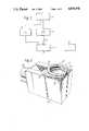
- FIG. 1is a schematic block diagram of an arrangement in accordance with the invention
- FIG. 2is a perspective view of a sensor head apparatus in accordance with the invention.
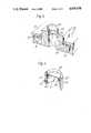
- FIG. 3is a part-sectional part-cut-away view of the apparatus shown in FIG. 2, the section being a longitudinal section,
- FIG. 4is a transverse sectional view of part of the apparatus shown in FIG. 3, and
- FIG. 5is a sectional view of part of a modified embodiment of the invention.
- an apparatus in accordance with the inventioncomprises an ultrasonic pulse transmitting and receiving assembly 1, which will be described hereinafter in greater detail.
- the assemblyincorporates a PVDF transducer which is mounted in such a way that the transducer can be accoustically coupled to the skin of a patient.
- the transmitter and receiver assembly 1is connected to receive pulses from a pulse generator 2, the pulse generator generating pulses of a frequency between 30 and 50 MHz.
- the pulse generatoris controlled by a computer 3.
- the transmitter and receiver 1is adapted to transmit the pulse from the pulse generator as an accoustic pulse, and to receive the "echos" of the accoustic pulse from the patient.
- the received signalsare transmitted to an analogue to digital convertor 4, which converts the received signal into 1024 pixels with eight bit precision.
- the analogue to digital convertoris thus able to convert the received "echo” in real time, and the digitised signal is then rapidly transverted to computer 3 by means of an IEEE 488 bus 5.
- the signalis rectified, and is passed through a low pass filter in order to distinguish the "echos" present in the echo signal.
- the signalcan be further processed within the computer.
- the transducer present in the receiver and transmitter 1may be moved relative to the skin of the patient, that is to say it may be scanned, and this scanning enables a two-dimensional representation to be generated by the computer for display on an appropriate display device 6, such as a colour monitor, and thus the apparatus may generate and display a two-dimensional representation of the skin of a patient.
- the transmitter and receiver assembly 1must, as will be appreciated from the foregoing description, consist of an transducer which can be accoustically coupled to the skin of a patient, but which can be accurately indexed or scanned relative to the patient.
- FIG. 2is an illustrative view of a pulse transmitting and receiving transducer assembly which consists of a main housing 10, on the upper surface of which is mounted a well 11.
- the well 11is effectively defined by an upstanding wall 12, defining, in the illustrated embodiment, an oval recess.
- the lower part of the recessis, as will be described hereinafter, sealed in a watertight manner, and is provided with a transducer 13 which can be moved axially within the well, by means of a motor 14.
- Two conduits 15, 16are provided which communicate with the interior of the well. Water may be injected into the well through the conduit 16 and may be withdrawn from the well through the conduit 15.
- the portion of the skin of a patient to be investigatedis brought into contact with the top surface of the wall 12 that defines the well 11.
- Watercan then be injected into the well through the conduit 16, until the water touches the skin of the patient. At this stage some water may escape between the upper surface of the wall 12 of the well and the skin of the patient, but this ensures that no air bubbles remain within the well.
- the transduceris then energised, the ultrasonic accoustic pulses generated by the transducer will be coupled, by the water, into the skin of the patient and equally any "echos" reflected by the interfaces present in the skin layers of the patient will again be coupled to the transducer by the water.
- the transducermay be indexed, within the well, as will be described hereinafter, thus enabling the described apparatus to be located in position on a patient, and to then perform an operational cycle in which the transducer is indexed or scanned between selected positions, the transducer transmitting ultrasonic pulses and receiving the corresponding "echo" pulses whilst at that location.
- the entire procedureis computer controlled, and the computer is able, as has been mentioned above, to generate a two-dimensional representation of the area of the skin of the patient undergoing the investigation.
- the watermay be withdrawn from the well 11 through the conduit 15, and the apparatus is then ready for re-use.
- the apparatusWhilst the apparatus has been shown in FIG. 2 in one orientation, it is to be appreciated that the apparatus may be brought into contact with any part of the skin of the patient, in any orientation, and then the well 11 may be filled by introducing water into the well through the conduit 16.
- the well 11is defined by an upstanding wall 12 which is formed integrally with a plate 17 which is screwed by means of screws 18 to the main housing 10.
- the upper part of the upstanding wall 12is provided with an elastomeric cover 19 to ensure that comfortable contact between the wall 12 and a patient can be established.
- the conduit 15is shown passing through an aperture formed in the upstanding wall 12, so that communication is established with the interior of the well 11, and the conduit 16 may pass through a corresponding aperture.
- the conduit 15is preferably mounted to direct a stream of water directly at the transducer.
- the lower part of the wall 12is provided with radially inwardly directed flange 20, the undersurface of which is provided with a recess 21, which is of annular form and is adapted to receive an O-ring 22.
- the O-ringacts to trap, within the annular recess 21, the upper part of a tubular flexible thin rubber membrane 23.
- the membrane 23forms a flexible bottom to the well 11, and may be termed a lower membrane.
- the lower part of the flexible membraneis secured by means of a further O-ring 24 to the exterior surface of an upstanding collar 25 formed integrally with a housing 26 in which a transducer 27 is mounted.
- the housing 26defines a vertical cylindrical bore 28, formed concentrically with the collar 25, the bore terminating within the collar 25.
- the transducer 27, which is of cylindrical configuration,is mounted within the bore 26, and two O-rings 29, 30 are located between the transducer and the wall defining the bore 28, to form a watertight seal.
- the described componentsconstitute a substantially watertight well, the wall 12 being formed integrally, and the flexible rubber membrane being sealed to the flange 20 formed integrally with the wall 11 by means of a sealing ring 21 and also being sealed to the collar 25 by means of a sealing ring 24.
- a space between the wall of the bore 28 and the transduceris sealed by means of the sealing rings 29, 30.
- the housing 26is mounted in such a way that it can slide axially of the housing 10.
- the housing 26is provided with two laterally projecting flanges 31, which co-operate with inwardly directed flanges 32 mounted on the longitudinal side walls of the housing 10.
- a linear bearing 33Located between the cooperating flanges is a linear bearing 33 and the arrangement is such that the components are retained in the relative position illustrated but the housing 26 may move axially.
- the housing 26is provided with grooves 34, 35, 36 to receive the O-rings 24, 29, 30 mentioned above.
- the housing 26 in which the transducer is mountedis provided with a projecting portion 37 which defines a transversely extending wall 38 provided with a threaded bore which receives a threaded rod 39.
- the threaded rodis coupled, by means of a part flexible coupling 40 to the drive shaft 41 of an electric motor 42.
- the electic motoris provided with an integral mounting plate 43 provided with apertures 44 through which screws 45 may be inserted to engage with appropriately provided apertures 46 present in a transverse wall 47 formed integrally with the housing 10.
- the wall 47is provided with an aperture 48 to accommodate the drive shaft 41 of the motor 42.
- the transverse wall 47is also provided with an appropriate inlet port 49 illustrated as being provided with a grommet 50 to receive an input tube 51 which contains the water supply and drain conduits 15 and 16, and an electric lead 52 leading to the transducer 27 and a further electric lead 53 which extends to a microswitch 54 the operating arm 55 of which engages a cam recess 56 formed on the undersurface of the housing 26.
- An appropriate electric leadis also provided (not shown) connected to the electric motor 42.
- a spring 57may be provided extending between the transverse wall 47 and the housing 26 to provide a bias to the housing 26 tending to draw the housing 26 towards the wall 47.
- conduits 15 and 16may be utilised to fill and empty the well as described above.
- the motor 42may be actuated, under the control of the computer, to rotate the threaded rod 39, thus driving the housing 26 axially.
- the cam 56actuates the microswitch 54.
- the direction of rotation of the motormay then be reversed, thus causing the housing 26 to move to the other limit position.
- the limit positions of the movable housing 26may be detected by means of an optical arrangement, or by means of Hall effect switches or other proximity sensing switches.
- the transducerWhilst the invention has been described with reference to a relatively simple embodiment in which the transducer is mounted for axial movement relative to the well, it is envisaged that it may be preferable to provide embodiments in which the transducer is not only movable axially of the well, but is also movable transversely to the well. It is thus envisaged that a further drive motor may be provided adapted to move the transducer assembly in a transverse direction. It is envisaged that it may also prove desirable to be able to move the transducer itself towards and away from the surface of water present in the well, and thus means may be provided to move the transducer, in the orientation shown in FIG. 3, in a vertical direction. Alternatively again it may be desirable to be able to tilt or pivot the transducer relative to the surface of the well, and again it is envisaged that means may be provided to perform this function.
- the open mouth of a collar 25'which defines a well 11' containing a transducer arrangement as described above is provided with a thin flexible sealing membrane 58, such as a thin rubber membrane.
- the membrane 58is stretched over a support ring 59 which has an annular groove 60 in its outer peripheral surface, and is sealingly trapped by a resilient O-ring 61 which is in the groove 60.
- the combination of the membrane 58 and support ring 59is a sealing friction fit in the open mouth of the well.
- a bore 62is provided through the wall of the well to enable the well to be filled, with an acoustic coupling fluid, such as water, and the bore may be sealed with a plug 63.
- an acoustic coupling gelis inserted in the space between the membrane 58 and the top of the well and the device is then used in a manner corresponding to that described above.
- This embodimentis easier to use, since the well does not need to be filled before an image is obtained. Also the device can be more easily utilised in positions where the open mouth of the well is directed downwardly.
- the wellmay, of course, be pre-filled with fluid and permanently sealed.
- the apparatus of the inventionmay be utilised in carrying out ultrasonic investigations of inanimate objects, as well as in carrying out ultrasonic investigations of living patients.
Landscapes
- Health & Medical Sciences (AREA)
- Life Sciences & Earth Sciences (AREA)
- Medical Informatics (AREA)
- Biophysics (AREA)
- Nuclear Medicine, Radiotherapy & Molecular Imaging (AREA)
- Pathology (AREA)
- Radiology & Medical Imaging (AREA)
- Engineering & Computer Science (AREA)
- Biomedical Technology (AREA)
- Heart & Thoracic Surgery (AREA)
- Physics & Mathematics (AREA)
- Molecular Biology (AREA)
- Surgery (AREA)
- Animal Behavior & Ethology (AREA)
- General Health & Medical Sciences (AREA)
- Public Health (AREA)
- Veterinary Medicine (AREA)
- Gynecology & Obstetrics (AREA)
- Pregnancy & Childbirth (AREA)
- Ultra Sonic Daignosis Equipment (AREA)
- Surgical Instruments (AREA)
Abstract
Description
Claims (12)
Applications Claiming Priority (2)
| Application Number | Priority Date | Filing Date | Title |
|---|---|---|---|
| GB8619579 | 1986-08-12 | ||
| GB868619579AGB8619579D0 (en) | 1986-08-12 | 1986-08-12 | Ultrasonic investigation apparatus |
Publications (1)
| Publication Number | Publication Date |
|---|---|
| US4870970Atrue US4870970A (en) | 1989-10-03 |
Family
ID=10602577
Family Applications (1)
| Application Number | Title | Priority Date | Filing Date |
|---|---|---|---|
| US07/190,689Expired - Fee RelatedUS4870970A (en) | 1986-08-12 | 1987-08-12 | Ultrasonic investigation apparatus |
Country Status (5)
| Country | Link |
|---|---|
| US (1) | US4870970A (en) |
| EP (1) | EP0276289B1 (en) |
| AU (1) | AU588478B2 (en) |
| GB (1) | GB8619579D0 (en) |
| WO (1) | WO1988001151A1 (en) |
Cited By (15)
| Publication number | Priority date | Publication date | Assignee | Title |
|---|---|---|---|---|
| US5303708A (en)* | 1992-07-27 | 1994-04-19 | Animal Ultrasound Services, Inc. | Grading of poultry carcasses with ultrasound |
| US5316003A (en)* | 1992-07-24 | 1994-05-31 | Animal Ultrasound Services, Inc. | Method and apparatus for positioning an ultrasonic transducer for longitudinal scanning of an animal or carcass |
| US5551432A (en)* | 1995-06-19 | 1996-09-03 | New York Eye & Ear Infirmary | Scanning control system for ultrasound biomicroscopy |
| US5617864A (en)* | 1995-08-04 | 1997-04-08 | Animal Ultrasound Services, Inc. | Method and apparatus for positioning an ultrasonic transducer and a display screen |
| DE19600577A1 (en)* | 1996-01-10 | 1997-07-17 | Reha Medical Gmbh | Positioning apparatus for female breast for diagnosis |
| DE19729408A1 (en)* | 1996-07-09 | 1998-01-15 | Siemens Ag | Ultrasound test head to test surface coupling apparatus |
| US5710378A (en)* | 1995-03-31 | 1998-01-20 | General Electric Company | Inspection tool for detecting cracks in jet pump beams of boiling water reactor |
| US6292682B1 (en)* | 1996-10-04 | 2001-09-18 | Optosonics, Inc. | Photoacoustic breast scanner |
| US6319227B1 (en)* | 1998-08-05 | 2001-11-20 | Scimed Life Systems, Inc. | Automatic/manual longitudinal position translator and rotary drive system for catheters |
| US6398755B1 (en) | 1998-10-06 | 2002-06-04 | Scimed Life Systems, Inc. | Driveable catheter system |
| WO2010092565A1 (en)* | 2009-02-13 | 2010-08-19 | Helix Medical Systems Ltd. | A method and a system for medical imaging |
| EP2253274A1 (en)* | 2009-05-20 | 2010-11-24 | Karlsruher Institut für Technologie | Device for ultrasound-supported computer tomography with expanded measurement range |
| WO2013014912A1 (en)* | 2011-07-26 | 2013-01-31 | Canon Kabushiki Kaisha | Property information acquiring apparatus |
| WO2013014911A1 (en)* | 2011-07-26 | 2013-01-31 | Canon Kabushiki Kaisha | Property information acquiring apparatus |
| US12343200B2 (en) | 2015-10-09 | 2025-07-01 | Boston Scientific Scimed, Inc. | Intravascular ultrasound systems, catheters, and methods with a manual pullback arrangement |
Families Citing this family (1)
| Publication number | Priority date | Publication date | Assignee | Title |
|---|---|---|---|---|
| WO2000056206A1 (en)* | 1999-03-23 | 2000-09-28 | Koninklijke Philips Electronics N.V. | Device for localizing an object in a turbid medium |
Citations (15)
| Publication number | Priority date | Publication date | Assignee | Title |
|---|---|---|---|---|
| US3480002A (en)* | 1967-01-24 | 1969-11-25 | Magnaflux Corp | Medical ultrasonic scanning system |
| US3854471A (en)* | 1972-09-15 | 1974-12-17 | J Wild | Ultrasonic method for systematic search and detection of tissue abnormalities |
| FR2294433A1 (en)* | 1974-12-10 | 1976-07-09 | Alsthom Savoisienne | Detector of pressure waves through wall - sensor inside liquid-filled enclosure ensuring transmission from wall to sensor |
| US4059098A (en)* | 1975-07-21 | 1977-11-22 | Stanford Research Institute | Flexible ultrasound coupling system |
| US4099420A (en)* | 1977-06-03 | 1978-07-11 | Cornell Research Foundation, Inc. | Transducer positioning apparatus |
| US4105018A (en)* | 1976-02-02 | 1978-08-08 | University Of Utah | Acoustic examination, material characterization and imaging of the internal structure of a body by measurement of the time-of-flight of acoustic energy therethrough |
| GB2015732A (en)* | 1978-03-03 | 1979-09-12 | Australia Dept Of Health | Rotating ultrasonic scanner |
| EP0018771A1 (en)* | 1979-04-26 | 1980-11-12 | Ontario Cancer Institute | Ultrasonic imaging device |
| US4275597A (en)* | 1977-07-11 | 1981-06-30 | Smithkline Instruments, Inc. | Ultrasonic beam scanning technique and apparatus |
| EP0032129A1 (en)* | 1980-01-07 | 1981-07-15 | Technicare Corporation | Ultrasound mammary scanning apparatus |
| US4398425A (en)* | 1981-08-03 | 1983-08-16 | Dymax Corporation | Ultrasonic scanning transducer |
| US4433690A (en)* | 1981-07-20 | 1984-02-28 | Siemens Ag | Compact ultrasound apparatus for medical examination |
| US4545385A (en)* | 1982-03-23 | 1985-10-08 | Siemens Aktiengesellschaft | Ultrasound examination device for scanning body parts |
| US4572202A (en)* | 1983-11-14 | 1986-02-25 | Elscint Inc. | Method and apparatus for high-speed ultrasonic imaging |
| US4681120A (en)* | 1984-02-03 | 1987-07-21 | Kabushiki Kaisha Toshiba | Ultrasonic diagnosing apparatus |
- 1986
- 1986-08-12GBGB868619579Apatent/GB8619579D0/enactivePending
- 1987
- 1987-08-12USUS07/190,689patent/US4870970A/ennot_activeExpired - Fee Related
- 1987-08-12EPEP87905240Apatent/EP0276289B1/ennot_activeExpired
- 1987-08-12AUAU77568/87Apatent/AU588478B2/ennot_activeCeased
- 1987-08-12WOPCT/GB1987/000570patent/WO1988001151A1/enactiveIP Right Grant
Patent Citations (15)
| Publication number | Priority date | Publication date | Assignee | Title |
|---|---|---|---|---|
| US3480002A (en)* | 1967-01-24 | 1969-11-25 | Magnaflux Corp | Medical ultrasonic scanning system |
| US3854471A (en)* | 1972-09-15 | 1974-12-17 | J Wild | Ultrasonic method for systematic search and detection of tissue abnormalities |
| FR2294433A1 (en)* | 1974-12-10 | 1976-07-09 | Alsthom Savoisienne | Detector of pressure waves through wall - sensor inside liquid-filled enclosure ensuring transmission from wall to sensor |
| US4059098A (en)* | 1975-07-21 | 1977-11-22 | Stanford Research Institute | Flexible ultrasound coupling system |
| US4105018A (en)* | 1976-02-02 | 1978-08-08 | University Of Utah | Acoustic examination, material characterization and imaging of the internal structure of a body by measurement of the time-of-flight of acoustic energy therethrough |
| US4099420A (en)* | 1977-06-03 | 1978-07-11 | Cornell Research Foundation, Inc. | Transducer positioning apparatus |
| US4275597A (en)* | 1977-07-11 | 1981-06-30 | Smithkline Instruments, Inc. | Ultrasonic beam scanning technique and apparatus |
| GB2015732A (en)* | 1978-03-03 | 1979-09-12 | Australia Dept Of Health | Rotating ultrasonic scanner |
| EP0018771A1 (en)* | 1979-04-26 | 1980-11-12 | Ontario Cancer Institute | Ultrasonic imaging device |
| EP0032129A1 (en)* | 1980-01-07 | 1981-07-15 | Technicare Corporation | Ultrasound mammary scanning apparatus |
| US4433690A (en)* | 1981-07-20 | 1984-02-28 | Siemens Ag | Compact ultrasound apparatus for medical examination |
| US4398425A (en)* | 1981-08-03 | 1983-08-16 | Dymax Corporation | Ultrasonic scanning transducer |
| US4545385A (en)* | 1982-03-23 | 1985-10-08 | Siemens Aktiengesellschaft | Ultrasound examination device for scanning body parts |
| US4572202A (en)* | 1983-11-14 | 1986-02-25 | Elscint Inc. | Method and apparatus for high-speed ultrasonic imaging |
| US4681120A (en)* | 1984-02-03 | 1987-07-21 | Kabushiki Kaisha Toshiba | Ultrasonic diagnosing apparatus |
Non-Patent Citations (6)
| Title |
|---|
| Benthin, Metal "Apparatus for Displaying Reflected UTGS Pulses", Intnl Appln (PCT) WO82/04183 publ. 12/1982. |
| Benthin, Metal Apparatus for Displaying Reflected UTGS Pulses , Intnl Appln (PCT) WO82/04183 publ. 12/1982.* |
| Chow, C. K. et al "Dig. Processor for Data Compaction and Image Enhancement of Echographic Signals", IBM Technical Disclosure Bulletin vol. 17, No. 10, pp. 3154-3158, Mar. 1975. |
| Chow, C. K. et al Dig. Processor for Data Compaction and Image Enhancement of Echographic Signals , IBM Technical Disclosure Bulletin vol. 17, No. 10, pp. 3154 3158, Mar. 1975.* |
| Taylor, W. B. et al "A High-Resolution Transrectal UTS System", UTS in Med & Biol. vol. 5, pp. 129-138. |
| Taylor, W. B. et al A High Resolution Transrectal UTS System , UTS in Med & Biol. vol. 5, pp. 129 138.* |
Cited By (20)
| Publication number | Priority date | Publication date | Assignee | Title |
|---|---|---|---|---|
| US5316003A (en)* | 1992-07-24 | 1994-05-31 | Animal Ultrasound Services, Inc. | Method and apparatus for positioning an ultrasonic transducer for longitudinal scanning of an animal or carcass |
| US5303708A (en)* | 1992-07-27 | 1994-04-19 | Animal Ultrasound Services, Inc. | Grading of poultry carcasses with ultrasound |
| US5710378A (en)* | 1995-03-31 | 1998-01-20 | General Electric Company | Inspection tool for detecting cracks in jet pump beams of boiling water reactor |
| US5551432A (en)* | 1995-06-19 | 1996-09-03 | New York Eye & Ear Infirmary | Scanning control system for ultrasound biomicroscopy |
| US5617864A (en)* | 1995-08-04 | 1997-04-08 | Animal Ultrasound Services, Inc. | Method and apparatus for positioning an ultrasonic transducer and a display screen |
| DE19600577A1 (en)* | 1996-01-10 | 1997-07-17 | Reha Medical Gmbh | Positioning apparatus for female breast for diagnosis |
| DE19729408A1 (en)* | 1996-07-09 | 1998-01-15 | Siemens Ag | Ultrasound test head to test surface coupling apparatus |
| US6292682B1 (en)* | 1996-10-04 | 2001-09-18 | Optosonics, Inc. | Photoacoustic breast scanner |
| US20020072704A1 (en)* | 1998-08-05 | 2002-06-13 | Idriss Mansouri-Ruiz | Automatic/manual longitudinal position translator and rotary drive system for catheters |
| US6319227B1 (en)* | 1998-08-05 | 2001-11-20 | Scimed Life Systems, Inc. | Automatic/manual longitudinal position translator and rotary drive system for catheters |
| US6814727B2 (en) | 1998-08-05 | 2004-11-09 | Scimed Life Systems, Inc. | Automatic/manual longitudinal position translator and rotary drive system for catheters |
| US20050043618A1 (en)* | 1998-08-05 | 2005-02-24 | Scimed Life Systems, Inc. | Automatic/manual longitudinal position translator and rotary drive system for catheters |
| US7613493B2 (en) | 1998-08-05 | 2009-11-03 | Boston Scientific Scimed, Inc. | Automatic/manual longitudinal position translator and rotary drive system for catheters |
| US6398755B1 (en) | 1998-10-06 | 2002-06-04 | Scimed Life Systems, Inc. | Driveable catheter system |
| US6974465B2 (en) | 1998-10-06 | 2005-12-13 | Boston Scientific Scimed, Inc. | Driveable catheter system |
| WO2010092565A1 (en)* | 2009-02-13 | 2010-08-19 | Helix Medical Systems Ltd. | A method and a system for medical imaging |
| EP2253274A1 (en)* | 2009-05-20 | 2010-11-24 | Karlsruher Institut für Technologie | Device for ultrasound-supported computer tomography with expanded measurement range |
| WO2013014912A1 (en)* | 2011-07-26 | 2013-01-31 | Canon Kabushiki Kaisha | Property information acquiring apparatus |
| WO2013014911A1 (en)* | 2011-07-26 | 2013-01-31 | Canon Kabushiki Kaisha | Property information acquiring apparatus |
| US12343200B2 (en) | 2015-10-09 | 2025-07-01 | Boston Scientific Scimed, Inc. | Intravascular ultrasound systems, catheters, and methods with a manual pullback arrangement |
Also Published As
| Publication number | Publication date |
|---|---|
| GB8619579D0 (en) | 1986-09-24 |
| AU588478B2 (en) | 1989-09-14 |
| AU7756887A (en) | 1988-03-08 |
| EP0276289B1 (en) | 1990-02-28 |
| WO1988001151A1 (en) | 1988-02-25 |
| EP0276289A1 (en) | 1988-08-03 |
Similar Documents
| Publication | Publication Date | Title |
|---|---|---|
| US4870970A (en) | Ultrasonic investigation apparatus | |
| US12156763B2 (en) | Wearable ultrasound system and method | |
| US5065740A (en) | Ultrasonic medical treatment apparatus | |
| DE69727994D1 (en) | Medical ultrasound diagnostic image system with scan display for a three-dimensional image display | |
| US20150065916A1 (en) | Fully automated vascular imaging and access system | |
| US20130237826A1 (en) | Precision ultrasonic scanner for body parts with extended imaging depth | |
| ATE186189T1 (en) | ULTRASONIC IMAGING SYSTEM | |
| KR20180098495A (en) | Conformal interface for medical diagnostic ultrasound imaging | |
| US20100286521A1 (en) | Multi-modal medical scanning method and apparatus | |
| JP6767575B2 (en) | Ultrasonic Transducer / Tile Alignment | |
| CN112638275B (en) | Shear wave detection of anatomical viscosity and associated devices, systems, and methods | |
| CA3215523A1 (en) | A portable ultrasound device and method for ultrasonic imaging | |
| CN113229848A (en) | Ultrasonic tomography detection method with solid coupling medium and breast detection device | |
| CN114343710A (en) | Diagnosis and treatment instrument | |
| US11710229B2 (en) | Methods and systems for shear wave elastography | |
| JP2746584B2 (en) | Ultrasound diagnostic equipment for endoscopes | |
| JP2002238898A (en) | Ultrasonic probe scanning device and ultrasonic diagnostic apparatus | |
| JP2006247007A (en) | Ultrasonic diagnostic coupler | |
| JPH07184902A (en) | Intracelom ultrasonic probe | |
| US10321847B2 (en) | Integrated tracking system for endocavity imaging | |
| US20230404529A1 (en) | Apparatus for ultrasound scanning | |
| EP0772891A1 (en) | Ultrasound imaging array | |
| JPS6054060B2 (en) | Ultrasound diagnostic equipment | |
| US20240050066A1 (en) | Robot-assisted tele-echography probe | |
| US20070016057A1 (en) | Medical device having gripping layer |
Legal Events
| Date | Code | Title | Description |
|---|---|---|---|
| AS | Assignment | Owner name:FULMER LIMITED, STOKE POGES, SLOUGH, BUCKS, SL2 4Q Free format text:ASSIGNMENT OF ASSIGNORS INTEREST.;ASSIGNORS:GRAY, NIGEL;KNIBBS, SIMON;FINLAY, PATRICK A.;AND OTHERS;REEL/FRAME:004926/0049 Effective date:19880406 | |
| FEPP | Fee payment procedure | Free format text:PAYER NUMBER DE-ASSIGNED (ORIGINAL EVENT CODE: RMPN); ENTITY STATUS OF PATENT OWNER: SMALL ENTITY Free format text:PAYOR NUMBER ASSIGNED (ORIGINAL EVENT CODE: ASPN); ENTITY STATUS OF PATENT OWNER: SMALL ENTITY | |
| AS | Assignment | Owner name:FULMER DYSON LIMITED, STOKE POGES, SLOUGH, BUCKS S Free format text:ASSIGNMENT OF ASSIGNORS INTEREST.;ASSIGNOR:FULMER LIMITED;REEL/FRAME:005252/0440 Effective date:19900215 | |
| AS | Assignment | Owner name:JACK CANTWELL, INC. Free format text:ASSIGNMENT OF ASSIGNORS INTEREST.;ASSIGNOR:FULMER DYSON LTD. (OWNED BY EVELYNA DYSON CANTWELL AND THE INSTITUTE OF PHYSICS);REEL/FRAME:005970/0844 Effective date:19910820 Owner name:JACK CANTWELL, INC. Free format text:ASSIGNMENT OF ASSIGNORS INTEREST;ASSIGNOR:FULMER DYSON LTD. (OWNED BY EVELYNA DYSON CANTWELL AND THE INSTITUTE OF PHYSICS);REEL/FRAME:005970/0844 Effective date:19910820 | |
| AS | Assignment | Owner name:TOPOX, INC., COLORADO Free format text:ASSIGNMENT OF ASSIGNORS INTEREST.;ASSIGNOR:JACK CANTWELL INC.;REEL/FRAME:005977/0910 Effective date:19911115 | |
| AS | Assignment | Owner name:JACK CANTEWELL, INC., NEW JERSEY Free format text:ASSIGNMENT OF ASSIGNORS INTEREST.;ASSIGNOR:FULMER DYSON LIMITED;REEL/FRAME:006284/0886 Effective date:19920810 | |
| FEPP | Fee payment procedure | Free format text:PAT HOLDER CLAIMS SMALL ENTITY STATUS - SMALL BUSINESS (ORIGINAL EVENT CODE: SM02); ENTITY STATUS OF PATENT OWNER: SMALL ENTITY | |
| FEPP | Fee payment procedure | Free format text:PAYOR NUMBER ASSIGNED (ORIGINAL EVENT CODE: ASPN); ENTITY STATUS OF PATENT OWNER: SMALL ENTITY | |
| REFU | Refund | Free format text:REFUND PROCESSED. MAINTENANCE FEE HAS ALREADY BEEN PAID (ORIGINAL EVENT CODE: R160); ENTITY STATUS OF PATENT OWNER: SMALL ENTITY | |
| AS | Assignment | Owner name:SUPRA MEDICAL CORP., PENNSYLVANIA Free format text:CHANGE OF NAME;ASSIGNOR:TOPOX, INC.;REEL/FRAME:006497/0082 Effective date:19921023 | |
| FPAY | Fee payment | Year of fee payment:4 | |
| FPAY | Fee payment | Year of fee payment:8 | |
| REMI | Maintenance fee reminder mailed | ||
| LAPS | Lapse for failure to pay maintenance fees | ||
| FP | Lapsed due to failure to pay maintenance fee | Effective date:20011003 | |
| STCH | Information on status: patent discontinuation | Free format text:PATENT EXPIRED DUE TO NONPAYMENT OF MAINTENANCE FEES UNDER 37 CFR 1.362 |