US4868843A - Multileaf collimator and compensator for radiotherapy machines - Google Patents
Multileaf collimator and compensator for radiotherapy machinesDownload PDFInfo
- Publication number
- US4868843A US4868843AUS07/072,814US7281487AUS4868843AUS 4868843 AUS4868843 AUS 4868843AUS 7281487 AUS7281487 AUS 7281487AUS 4868843 AUS4868843 AUS 4868843A
- Authority
- US
- United States
- Prior art keywords
- radiation
- leaf
- subject
- ray
- field
- Prior art date
- Legal status (The legal status is an assumption and is not a legal conclusion. Google has not performed a legal analysis and makes no representation as to the accuracy of the status listed.)
- Expired - Lifetime
Links
- 238000001959radiotherapyMethods0.000titleclaimsabstractdescription12
- 230000005855radiationEffects0.000claimsabstractdescription105
- 238000011282treatmentMethods0.000claimsdescription71
- 238000000034methodMethods0.000claimsdescription23
- 239000011888foilSubstances0.000claimsdescription19
- 238000002560therapeutic procedureMethods0.000claimsdescription18
- 238000009826distributionMethods0.000claimsdescription15
- 238000003780insertionMethods0.000claimsdescription14
- 230000037431insertionEffects0.000claimsdescription14
- 238000007493shaping processMethods0.000claimsdescription10
- 230000033001locomotionEffects0.000claimsdescription9
- 230000009977dual effectEffects0.000claimsdescription7
- 230000000670limiting effectEffects0.000claimsdescription7
- 238000012544monitoring processMethods0.000claimsdescription7
- 230000000712assemblyEffects0.000claimsdescription5
- 238000000429assemblyMethods0.000claimsdescription5
- 230000000903blocking effectEffects0.000claimsdescription5
- 239000000463materialSubstances0.000claimsdescription4
- 238000001803electron scatteringMethods0.000claimsdescription3
- 230000003068static effectEffects0.000claimsdescription3
- 239000012472biological sampleSubstances0.000claims1
- 238000013170computed tomography imagingMethods0.000claims1
- 230000001678irradiating effectEffects0.000claims1
- 206010028980NeoplasmDiseases0.000abstractdescription18
- 230000001788irregularEffects0.000abstractdescription13
- 210000000056organAnatomy0.000abstractdescription8
- 229910001385heavy metalInorganic materials0.000abstractdescription2
- WFKWXMTUELFFGS-UHFFFAOYSA-NtungstenChemical compound[W]WFKWXMTUELFFGS-UHFFFAOYSA-N0.000description23
- 229910052721tungstenInorganic materials0.000description23
- 239000010937tungstenSubstances0.000description23
- 230000005540biological transmissionEffects0.000description11
- 210000001519tissueAnatomy0.000description11
- 238000010586diagramMethods0.000description9
- 239000013078crystalSubstances0.000description8
- 238000002591computed tomographyMethods0.000description7
- 238000010894electron beam technologyMethods0.000description7
- 230000000717retained effectEffects0.000description6
- 230000035945sensitivityEffects0.000description6
- 231100000987absorbed doseToxicity0.000description5
- 210000003484anatomyAnatomy0.000description4
- 230000008859changeEffects0.000description4
- 238000012937correctionMethods0.000description4
- 239000000835fiberSubstances0.000description4
- 210000004072lungAnatomy0.000description4
- 230000002829reductive effectEffects0.000description4
- QYSXJUFSXHHAJI-YRZJJWOYSA-Nvitamin D3Chemical compoundC1(/[C@@H]2CC[C@@H]([C@]2(CCC1)C)[C@H](C)CCCC(C)C)=C\C=C1\C[C@@H](O)CCC1=CQYSXJUFSXHHAJI-YRZJJWOYSA-N0.000description4
- 230000008901benefitEffects0.000description3
- 238000009201electron therapyMethods0.000description3
- 210000000867larynxAnatomy0.000description3
- 229910052751metalInorganic materials0.000description3
- 239000002184metalSubstances0.000description3
- 230000000149penetrating effectEffects0.000description3
- 230000008569processEffects0.000description3
- 238000003860storageMethods0.000description3
- 206010057362UnderdoseDiseases0.000description2
- 229910052782aluminiumInorganic materials0.000description2
- 210000000038chestAnatomy0.000description2
- 238000011443conventional therapyMethods0.000description2
- 238000013461designMethods0.000description2
- 238000003384imaging methodMethods0.000description2
- 210000001165lymph nodeAnatomy0.000description2
- 238000004519manufacturing processMethods0.000description2
- 230000002441reversible effectEffects0.000description2
- 210000000278spinal cordAnatomy0.000description2
- RYGMFSIKBFXOCR-UHFFFAOYSA-NCopperChemical compound[Cu]RYGMFSIKBFXOCR-UHFFFAOYSA-N0.000description1
- ZOKXTWBITQBERF-UHFFFAOYSA-NMolybdenumChemical compound[Mo]ZOKXTWBITQBERF-UHFFFAOYSA-N0.000description1
- 210000001015abdomenAnatomy0.000description1
- 239000006096absorbing agentSubstances0.000description1
- XAGFODPZIPBFFR-UHFFFAOYSA-NaluminiumChemical compound[Al]XAGFODPZIPBFFR-UHFFFAOYSA-N0.000description1
- 239000012620biological materialSubstances0.000description1
- 229910052797bismuthInorganic materials0.000description1
- JCXGWMGPZLAOME-UHFFFAOYSA-Nbismuth atomChemical compound[Bi]JCXGWMGPZLAOME-UHFFFAOYSA-N0.000description1
- 210000004556brainAnatomy0.000description1
- 210000000481breastAnatomy0.000description1
- 229910052793cadmiumInorganic materials0.000description1
- BDOSMKKIYDKNTQ-UHFFFAOYSA-Ncadmium atomChemical compound[Cd]BDOSMKKIYDKNTQ-UHFFFAOYSA-N0.000description1
- 201000011510cancerDiseases0.000description1
- 239000003086colorantSubstances0.000description1
- 230000000295complement effectEffects0.000description1
- 238000010276constructionMethods0.000description1
- 229910052802copperInorganic materials0.000description1
- 239000010949copperSubstances0.000description1
- 230000003247decreasing effectEffects0.000description1
- 238000011161developmentMethods0.000description1
- 230000000694effectsEffects0.000description1
- 230000008030eliminationEffects0.000description1
- 238000003379elimination reactionMethods0.000description1
- 238000001914filtrationMethods0.000description1
- 208000014829head and neck neoplasmDiseases0.000description1
- 230000036541healthEffects0.000description1
- 238000002347injectionMethods0.000description1
- 239000007924injectionSubstances0.000description1
- 230000005865ionizing radiationEffects0.000description1
- 230000004807localizationEffects0.000description1
- 239000000314lubricantSubstances0.000description1
- 210000002751lymphAnatomy0.000description1
- 230000013011matingEffects0.000description1
- 230000003340mental effectEffects0.000description1
- 238000012986modificationMethods0.000description1
- 230000004048modificationEffects0.000description1
- 229910052750molybdenumInorganic materials0.000description1
- 239000011733molybdenumSubstances0.000description1
- CWQXQMHSOZUFJS-UHFFFAOYSA-Nmolybdenum disulfideChemical compoundS=[Mo]=SCWQXQMHSOZUFJS-UHFFFAOYSA-N0.000description1
- 229910000595mu-metalInorganic materials0.000description1
- 230000003287optical effectEffects0.000description1
- 230000036961partial effectEffects0.000description1
- 210000004197pelvisAnatomy0.000description1
- 230000035515penetrationEffects0.000description1
- 238000012545processingMethods0.000description1
- 238000002601radiographyMethods0.000description1
- 230000006798recombinationEffects0.000description1
- 238000005215recombinationMethods0.000description1
- 230000009467reductionEffects0.000description1
- 231100000817safety factorToxicity0.000description1
- 239000007787solidSubstances0.000description1
- 230000003595spectral effectEffects0.000description1
- 238000012360testing methodMethods0.000description1
- 210000000115thoracic cavityAnatomy0.000description1
- 238000003325tomographyMethods0.000description1
- 238000012876topographyMethods0.000description1
- 238000012546transferMethods0.000description1
- PBYZMCDFOULPGH-UHFFFAOYSA-NtungstateChemical compound[O-][W]([O-])(=O)=OPBYZMCDFOULPGH-UHFFFAOYSA-N0.000description1
- 238000012800visualizationMethods0.000description1
- 229910000859α-FeInorganic materials0.000description1
Images


Classifications
- G—PHYSICS
- G21—NUCLEAR PHYSICS; NUCLEAR ENGINEERING
- G21K—TECHNIQUES FOR HANDLING PARTICLES OR IONISING RADIATION NOT OTHERWISE PROVIDED FOR; IRRADIATION DEVICES; GAMMA RAY OR X-RAY MICROSCOPES
- G21K1/00—Arrangements for handling particles or ionising radiation, e.g. focusing or moderating
- G21K1/02—Arrangements for handling particles or ionising radiation, e.g. focusing or moderating using diaphragms, collimators
- G21K1/04—Arrangements for handling particles or ionising radiation, e.g. focusing or moderating using diaphragms, collimators using variable diaphragms, shutters, choppers
- G21K1/046—Arrangements for handling particles or ionising radiation, e.g. focusing or moderating using diaphragms, collimators using variable diaphragms, shutters, choppers varying the contour of the field, e.g. multileaf collimators
- A—HUMAN NECESSITIES
- A61—MEDICAL OR VETERINARY SCIENCE; HYGIENE
- A61N—ELECTROTHERAPY; MAGNETOTHERAPY; RADIATION THERAPY; ULTRASOUND THERAPY
- A61N5/00—Radiation therapy
- A61N5/10—X-ray therapy; Gamma-ray therapy; Particle-irradiation therapy
- A61N5/1042—X-ray therapy; Gamma-ray therapy; Particle-irradiation therapy with spatial modulation of the radiation beam within the treatment head
- A61N5/1045—X-ray therapy; Gamma-ray therapy; Particle-irradiation therapy with spatial modulation of the radiation beam within the treatment head using a multi-leaf collimator, e.g. for intensity modulated radiation therapy or IMRT
- A—HUMAN NECESSITIES
- A61—MEDICAL OR VETERINARY SCIENCE; HYGIENE
- A61N—ELECTROTHERAPY; MAGNETOTHERAPY; RADIATION THERAPY; ULTRASOUND THERAPY
- A61N5/00—Radiation therapy
- A61N5/10—X-ray therapy; Gamma-ray therapy; Particle-irradiation therapy
- A61N2005/1092—Details
- A61N2005/1095—Elements inserted into the radiation path within the system, e.g. filters or wedges
Definitions
- This inventionpertains to an apparatus and method for radiation treatment employing shaping and dynamic control of spatial distribution of intensity of the radiation field in a radiotherapy machine and in the application of such radiation in a selective manner to living biological materials including human patients in patient therapy for cancer treatment.
- Conventional x-ray treatment of a tumor in a patientis carried out by planning the radiation angles and dosage by taking into consideration safety factors in respect to the patient's organs which would be in the path of the beam.
- the treatment planassumes that the treatment equipment has certain capabilities. Accordingly, the current treatment practice assumes that the machine can cause a beam of selected rectangular shape and intensity to intersect a central fixed point in space from any solid angle. Therefore, the positioning of the patient and the use of multiple positions and multiple beam directions enable one to obtain integrated high doses on selected areas while maintaining low irradiation of other organs.
- control of the outline of the cross-section of the x-ray beamwas accomplished by using jaw devices and control of the intensity of the beam was possible by using absorber plates or accelerator energy controls which provide uniform intensity across the beam cross-section.
- Irregular shape field boundariesare then obtained by mounting shadow blocks on a shadow tray and irregular intensity across the cross-section is obtained by use of wedge filters or compensating filters (which are shaped pieces of metal), all of which are inserted between the jaws and the patient.
- My inventionpermits an entirely new method of treatment which eliminates the need for shadow blocks, wedge filters and compensating filters of the prior art and reduces the workload for the radiation technologists in treatment of the patient, while at the same time permits much improved precision in the two dimensional intensity distribution shaping of the resulting dose distribution in the patient. Furthermore, since my invention enables this beam shaping and intensity distribution control to be accomplished dynamically, it enables use of more effective treatment programs which would have been impractical in the prior art.
- rectangular field shapesare formed by four motor driven jaws in the radiation head. Irregular field shapes for individual portals are then produced by mounting shadow blocks on a shadow tray between the jaws and the patient.
- the shadow blocksshield critical organs not invaded by the tumor.
- the radiation beamcan be directed at the prescribed treatment volume from a single direction (single port therapy), from two or more directions (multi-port therapy), or the beam can be swept through an arc (arc or rotation therapy), all by rotating an isocentric gantry, for example.
- a cylindrical-shaped region of high doseis produced by a rectangular field in multi-port, arc or rotation therapy.
- the shadow blocksare changed for each beam angle. If the beam angle is not vertical, the shadow blocks must be locked to the shadow tray to avoid their falling off. Handling these blocks individually or on shadow trays is time-consuming.
- the shadow blocksare typically made by pouring a heavy metal into a pre-cut mold, which is also time-consuming.
- the shadow blockscan be heavy, difficult to handle, and dangerous if they fall on the patient or the radiotherapy personnel.
- arc or rotation therapyit is not practicable to change the shadow blocks continually or in small steps of beam angle. Also, this can require that the technologist go back into the shielded treatment room for each treatment field, a time-consuming process.
- the usual treatment field shapesresult in a three-dimensional treatment volume which includes segments of normal tissue, thereby limiting the dose that can be given to the tumor.
- the irradiation dose that can be delivered to a portion of an organ of normal tissue without serious damagecan be increased if the size of that portion of the organ receiving such radiation dose can be reduced. Avoidance of serious damage to the organs surrounding and overlying the tumor determines the maximum dose that can be delivered to the tumor. Cure rates for many tumors are a steep function of the dose delivered to the tumor. Techniques are reportedly under development to make the treatment volume conform more closely to the shape of the tumor volume, thereby minimizing the product of volume and dose to normal tissue, with its attendant effects on the health of the patient.
- This other techniquecould possibly permit higher dose to tumors or can result in less damage to normal tissue.
- These techniquesreportedly involve moving the x-ray jaws during treatment, scanning the x-ray beam or using multileaf collimators.
- multileaf equipmenthas not been capable of shaping internal regions of the field, e.g., islands and longitudinal peninsulas.
- one set of jawsis set to form a narrow (e.g., 4 cm) fan x-ray beam and the spread of the fan beam is varied by the second set of jaws to conform to the boundaries of the prescribed treatment volume as the beam is swept or stepped in angle around the patient and as the patient and associated table top are moved through the fan beam.
- a computercontrols the movements of the table top in x, y and z, the gantry angle, the upper jaws during start and stop of the scan, the lower jaws throughout the scan, and the dose rate.
- the complexityis such that great care must be exercised in preparing for such treatments, which consumes considerable time.
- a techniquehas also been proposed in which a narrow collimated lobe of x-rays is scanned over the treatment field, permitting production of irregular field shapes at selected beam angles. Because only a small fraction of the x-ray output is within the narrow lobe, the effective dose rate is low and the time to produce a portal field is hence long and multi-port treatment times are excessively long. Also, scanning individual fields is not readily applicable to arc and rotation therapy modes.
- each of the lower pair of jawsis divided into a number (e.g., 5 to 32) of narrow bars called leaves.
- Each leafmay be about 8 cm thick (in the beam direction) to provide adequate attenuation of the x-ray beam (down to about 1%), about 0.5 to 1.5 cm wide and about 14 cm long physically (not SAD).
- Each leafcan be moved independently by a motor drive. This permits the production of irregularly shaped fields with stepped boundaries, thereby avoiding shadow blocks for many situations in portal therapy. The shape can be changed as the beam direction is swept in arc or rotation therapy.
- the disadvantage of this technique of replacing the lower jaws by a multiplicity of leavesis that each leaf is quite large and heavy, requiring a motor drive system which consumes considerable space. There is limited room in the radiation head for all these components so either sacrifices in performance are made (such as fewer leaves, limited field size) or the construction costs become large.
- each leafmoves in a plane, driven by a rotating cam or pushed by a form corresponding to the desired irregular field shape.
- each leafwas thick enough to attenuate the x-ray beam to the required level (to about 5% of unattenuated beam intensity), the ends and sides of the leaf forming a rectangular parallelpiped, hence the ends and sides were not aimed toward the x-ray source.
- a multiplicity of small diameter rodsforms a stack sufficiently thick to provide the required beam attenuation. Each rod can slide with respect to its neighbors.
- a form corresponding to the desired field shape boundaryis used to push the assembly of rods so that their ends form a similar beam boundary. Since the rods are small in diameter, the radiation field boundary can be relatively smooth (very small steps) and tapered (focused) toward the source. However, varying the field shape as a function of beam angle without entering the treatment room can require a quite complex drive system because the large number of rods requires that they be driven enmasse instead of individually.
- Wedge filtersare pieces of metal which are tapered in one direction but of constant thickness in the orthogonal direction. They are used to produce a more uniform dose distribution in a treatment volume when it is irradiated from two directions which are less than 180° apart. And they are used at any gantry angle as a crude compensation for the variation in depth from the patient's surface to the plane at treatment depth. In both cases, only an approximate correction of dose distribution in the treatment volume is achieved.
- standard wedgesare used, with wedge angles of 15°, 30°, 45° and 60°. Intermediate angles are achieved by using two exposures per field, one with wedge filter, one without. Since manual insertion and retraction of wedges is laborious, fixed angle (typically 60°) auto-retractable wedge filters have been developed. Essentially all wedged fields then require two exposures, one with the wedge filter, one without. This is a time-consuming process, especially in rotational therapy, since an extra gantry rotation is required.
- Compensatorsoften termed compensation filters, are formed or assembled pieces of metal which are shaped to match the patient's demagnified anatomical shape so as to attenuate the x-ray beam by the amount that would have occurred if the patient thickness to depth of treatment plane were uniform.
- their usehas been more limited because of the needs for custom shaping for each patient and manual insertion for each field.
- Computed tomography (CT) images for treatment planningare typically obtained in successive planes which are normal to the patient axis. After transfer of these images, internal structures, target volume and patient surface can be outlined directly on the treatment planning computer display.
- CTComputed tomography
- correctionis required for divergence of the x-ray beam in the direction through the successive CT planes. This is a computation chore (beam's eye view) for the treatment planner and a mental visualization chore for the radiation therapist.
- An object of the inventionis to provide an improved method of radiation treatment enabling more resolution and precision in treatment by more precisely enabling control of the radiation intensity distribution across the fan beam cross section.
- a further objectis to enable dynamic, real time changes in the cross section intensity distribution of the fan beam to provide more effective patient treatment.
- a further object of the inventionis to provide a new system or an accessory to conventional medical electron accelerators and to radiation treatment and like techniques to permit dynamic control of three-dimensional spatial distribution of radiation dose in a treatment volume of arbitrary external and internal shape employing a fan x-ray beam which can be delivered, for example, in the same parallel planes in the patient as the computed tomography (CT) imaging planes.
- CTcomputed tomography
- a fan x-ray beamsuch as is produced by employing a slit aperture in conjunction with an x-ray source, is established. This could be accomplished using the collimator jaws of a conventional medical linac to produce a rectangular slit field at normal treatment distance.
- a multileaf collimator (MLC)is positioned in the fan beam including a first set of leaves which can be individually moved into or out of the fan x-ray beam to block or pass individual radiation pixels. Continuous monitoring of alignment of the patient's anatomy with both inner and outer edges of the fan beam is obtained with a linear detector array retractably mounted on the opposite side of the patient from the x-ray source.
- Tapered extensionsadded to a second opposite set of leaves of the MLC are variably positionable to attenuate the dose rate in individual radiation pixels of the fan x-ray beam.
- the patient scanis obtained by moving the patient perpendicularly to and through the fan x-ra field while the dose delivered in each radiation pixel is dynamically controlled.
- Normal tissueis protected by the positions of the first set of leaves of the MLC, which attenuate transmission to less than 5% of open field dose.
- Depth variations from the patient surface to the plane at treatment depthare compensated at each radiation pixel of the field by the positions of the tapered extensions of the second, opposite, set of leaves of the MLC, providing variable transmission from 50% to 100% of open field dose, for example. Reduced dose to critical organs such as the spinal cord can thereby be delivered in each treatment fraction.
- an open field dose of 300 cGy at depth of dose maximum (D-max)can be delivered to a 40 ⁇ 40 cm field in 240 seconds (4 minutes), with individual control of dose in each of 1600 1 ⁇ 1 cm radiation pixels.
- the MLCcan be constructed as an accessory to a standard conventional radiotherapy machine wherein by retraction of the compensator fingers to their storage positions on the MLC leaves, multileaf collimation of irregular fields is retained. By retracting the MLC leaves to their support frames, conventional x-ray therapy with the four jaws in the radiation head is retained using shadow blocks for irregular fields. Conventional electron therapy is also retained.
- interlock sensors for excess electron beam current and collapsed electron beam lobeare installed in the radiation head. Since the MLC could be installed in the space normally occupied by the conventional wedge filter tray, an automatic retractable support tray system for opposed angle wedge filters and for custom compensators would be mounted inside the radiation head.
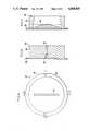
- FIG. 1is a view from the x-ray source of multiple-leaf fields according to the invention.
- FIG. 1ashows the leaves in the configuration for a right oblique treatment of the region of FIGS. 2-5.
- FIG. 1bshows the leaves in the configuration for a right lateral treatment of the region of FIGS. 2-5.
- FIG. 2is an illustration of a complex target region for use of the invention, the region of cervix-pelvic nodes-para-aortic lymph nodes region based on: Chin, L. M., et al, "Int. J. Radiation Oncology, Biol., Phys" Vol. 7, pp 61-70.
- FIG. 3is a section of the target region in the patient mid-saggital section plane 3--3 of FIG. 2.
- FIG. 4is a section of the target region in the section plane 4--4 of FIG. 3.
- FIG. 5is a section of the target region in the section plane 5--5 of FIG. 3.
- FIG. 6is a sectional view of the collimator according to the invention as shown in the section plane 6--6 of FIG. 7.
- FIG. 7is a sectional view of the collimator according to the invention as shown in the section plane 7--7 of FIG. 8.
- FIG. 8is a view of the collimator of the invention as seen from the patient treatment region looking toward the x-ray source.
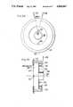
- FIG. 9is a view from the bottom of a fan x-ray beam flattening filter with inherent shielding.
- FIG. 10is a sectional view of the filter of FIG. 9 along the section line 10--10 in FIG. 9.
- FIG. 11is a sectional view of the filter of FIG. 9 along the section line 11--11 of FIG. 9.
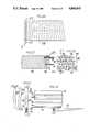
- FIG. 12is an end view of the assembly showing attachment of collimator fingers to MLC leaves.
- FIG. 13is a side view of the assembly of FIG. 12 along the section line 13--13 of FIG. 12.
- FIG. 14is a section of an alternate embodiment of the MLC leaves shown in FIG. 12.
- FIG. 15is a section of a second alternate embodiment of the MLC leaves shown in FIG. 12.
- FIG. 16shows a gantry mounted linear array detector
- FIG. 17is a sectional view of the detector array shown in FIG. 16 along the section line 17--17.
- FIG. 18is a sectional view of the array shown in FIG. 17 along the section line 18--18.
- FIG. 19is a sectional view of the array shown in FIG. 18 along the section line 19--19.
- FIG. 20is a block diagram of the electronics system for the linear array detector of FIGS. 16-19.
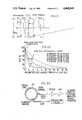
- FIG. 21is a diagram defining the parameters for calculating the multileaf penumbra for various shaped leaf ends.
- FIG. 22is a plot of the penumbra for the configurations defined in FIG. 21.
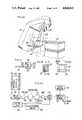
- FIG. 23shows a forty-leaf collimator showing support motor drive with compensator fingers attached as viewed from isocenter.
- FIG. 24is a sectional view of the collimator of FIG. 23 along the section line 24--24 from the side with compensator fingers attached.
- FIG. 25is a sectional view of the collimator of FIG. 23 along the section line 25--25.
- FIG. 26is a sectional view of the collimator of FIG. 23 along the section line 26--26 to show the curved end tapered MLC leaves.
- FIG. 27is a sectional view of the collimator of FIGS. 23-26 along section line 27--27, showing frames, lead screws, ball bearings and support rods.
- FIG. 28is a sectional view of the collimator of FIGS. 23-27 along section line 28--28.
- FIG. 29is a diagram of a radiation treatment plan which is possible using the invention.
- FIG. 30is a longitudinal section through the subject of the diagram of FIG. 29.
- FIG. 31is a cross section diagram through the subject of the diagram of FIG. 29.
- FIG. 32shows control and monitoring electronics for MLC and compensator fingers.
- FIG. 33shows a schematic diagram of a toroid beam pulse sensing system.
- FIG. 34shows a top view of a pressurized and interlocked dual foil electron scatterer.
- FIG. 35is a sectional view of the device of FIG. 34 along the section line 35--35.
- FIG. 36is a top view of an evacuated and interlocked dual foil electron scatterer.
- FIG. 37is a sectional view of the device of FIG. 36 along the section line 37--37.
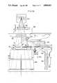
- FIG. 38shows a radiation head with insert system for conventional static compensator and automatic wedge filter and with toroid beam sensor.
- FIG. 39is a sectional view of the system of FIG. 38 along the section line 39--39.
- FIG. 40is a sectional view of the system of FIG. 38 along the section line 40--40.
- cGycentiGray, 10 -2 Joules per kilogram of absorbed dose, a unit of mean energy imparted by ionizing radiation to matter.
- compensator filterdevice which modifies the distribution of absorbed dose over the radiation field.
- depth doseabsorbed dose at a specified depth beneath the entrance surface of the irradiated object.
- D-maxdepth of maximum absorbed dose
- flattening filterdevice which homogenizes the absorbed dose over the radiation field.
- imaging pixelrectangular elements which together add to form an image.
- isocenterthe position around which the radiation x-ray therapy source moves to achieve optimum treatment of a tumor in a patient.
- MeVmillion electron-volts.
- MLCmultileaf collimator
- penumbrafringe at edges of the radiation field, where the radiation intensity falls off rapidly with distance from the full intensity region of the field.
- radiation pixelrectangular elements of radiation which together add to form the radiation field.
- SADsource-axis distance, the distance from the x-ray source to the isocenter.
- SSDsource-skin distance, the distance from the x-ray source to the skin of the patient.
- tomographyradiography of layers (slices) within the patient.
- FIG. 1an example of multileaf field shapes of the collimator 10 mounted in a flat cylinder 11 for a complex shaped clinical site, the region of cervix-pelvic nodes-para aortic nodes, as illustrated in FIG. 2.
- the fieldis 36 cm long. Its irregular width is defined by 24 pairs of leaves 12, each producing a 1.5 cm strip shadow in the radiation field at SAD (source-axis distance).
- SADsource-axis distance
- FIG. 1is drawn assuming that both upper and lower conventional jaws are used to define the field rectangular limits (36 cm long, 15 cm wide at 30° gantry angle, 13.5 cm wide at 90° gantry angle) and that the multileaf system simply provides the extra shadow blocking required within the rectangle.
- Thispermits shallow leaves 12 of 4.5 cm (1.77 inch) thickness tungsten (18.2 g/cm 3 ) for 5% transmission, the usual shielding criterion for shadow blocks, instead of 7 cm or more thickness tungsten for 1% transmission, the usual criterion for jaws.
- the maximum extension of any leaf into the field in FIG. 1is only 9 cm at SAD and only 2 cm beyond centerline.
- FIGS. 6-8show such a design.
- the leaves 12are mounted in the space presently occupied by the wedge mount of one type of conventional radiotherapy machine, at 52.6 cm from the x-ray source.
- Each leaf 12 actual dimensionis on 0.786 cm (0.31 inch) pitch, is 4.5 cm (1.77 inch) deep, 7.0 cm (2.75 inches) long, and weighs 0.45 kg (0.99 pound) of 18.2 g/cm 3 density tungsten.
- the total of 13 leaf pairsweighs 11.7 kg (25.7 pounds).
- Each multileaf half assembly 14, 16is mounted on a leaf support frame 18, 20 which can be moved in concert with its corresponding lower jaw 22, 23, either by lever connection to the jaw or by chain or other connection to the drive for that jaw or preferably by independent electrical drive 24 for each half frame.
- Each independent electrical drive 24is mounted to the cylinder 11 and is coupled by gears, belts or chains to a threaded shaft 25 which drives a leaf support frame sliding on rod 26 and attached to a threaded bushing 27.
- the maximum distance any leaf must travelis only the maximum distance it can project into the rectangular field defined by the upper and lower jaws; in this example, 6.6 cm (2.6 inches) actual travel distance relative to the frame.
- one multileaf half assembly 14, 16can be driven as a monoblock to provide dynamic wedge fields up to 12 cm. If the lower jaws are driven independently but are not enlarged in width and travel only up to field center, the multileaf half assembly can be driven as a monoblock to travel 12 cm beyond field center, thereby providing dynamic wedge fields up to 24 cm.
- independent jawscan be smaller in combination with the multileaf system than if the independent jaws themselves must be driven past field center and their tails still shield the primary collimator opening.
- each leaf 12is actually comprised of two sub-leaves 28, 29, one above the other.
- upperis taken as meaning closer to the radiation source and lower to mean further from the radiation source.
- the lower sub-leaf 29travels slightly faster than the upper sub-leaf 28, so that their ends are staggered to match the angle from the x-ray target.
- the lower sub-leaf 29is also slightly wider (2.2 mm in this example) than the upper sub-leaf 28, so that their sides are staggered to match the angle from the x-ray target in the direction at 90° to the leaf travel.
- Each sub-leafis supported by two rods 30, 32 (e.g., 1/8 inch diameter) which pass through two bushings 34, 36 (e.g., 1/4 inch outside diameter) in a frame 18, 20, and a threaded shaft 38 (e.g., 1/8 inch diameter) which passes through a threaded hole 40 in the frame.
- the individual sub-leaves 28, 29have sufficient clearance (e.g., 0.2 mm) so that they do not rub on each other, hence avoiding extra friction and the need for radiation resistant dry lubricant (e.g., molybdenum disulphide) in the x-ray beam.
- Each lower sub-leaf 29is motor-driven back and forth on micro-processor (not shown) command via the threaded shaft 38, driven through flexible cable 42 from a gear motor 44.
- the weight of each pair of sub-leaves 28, 29is about 1 pound, and this weight would need to be supported at 90° gantry angle. It would be desirable to be able to change any leaf position by 5 cm (SAD) in 5° of gantry rotation (0.83 seconds). Adding gear friction, etc., 5 pounds force over 2.7 cm actual travel in 0.8 seconds corresponds to 6.5 inch pounds per second or 10 -3 horsepower, permitting use of a miniature gear motor 44 for each pair of sub-leaves 28, 29, total of 26 such motors for 13 sub-leaf pairs, 13 motors per side.
- each split leafis driven at a slightly lower speed via two spur gears 46, 48 at the gear motor.
- a rotation counter(not shown) can be installed in the flexible cable drive to each sub-leaf, or to just the upper or lower set of sub-leaves.
- Each turn of the cable to a 1/8 inch diameter 12:1 lead screwcorresponds to about 0.5 mm change in field edge at SAD.
- a plus or minus signal for plus or minus one rotationwill be sent to a summing circuit and the position of the field edge of each leaf will be displaced digitally and on a CRT. The power to the motor drive will be stopped when this display corresponded to the value of field edge previously set for that leaf at that gantry angle.
- the upper sub-leaves 28are supported on subframes 50, 52 the lower sub-leaves 29 on frames 18, 20. Both subframes 50, 52 are driven from the existing lower jaw drive. Alternatively, motors 54 can be added to drive each frame under control signals independent of the jaw drives.
- the upper subframe 50is driven slightly slower than the lower subframe 52 by a correction motor 54, chain 56 and sprocket 58, such that upper subframe slides on rods 60 and such that the frame ends are staggered to match the jaw face slope. The stagger of the sub-leaf ends is then correct for all jaw positions.
- FIG. 7is a drawing showing the planar multileaf system in the vertical space normally occupied by the wedge mount.
- the left side of the collimator 10shows the lower jaw 22 set for a 20 cm conventional field, with leaves penetrating to 2 cm beyond field axis.
- the right side of the collimatorshows the lower jaw 23 set for a 40 cm conventional field, with the leaves fully withdrawn. This establishes the required diameter of the multileaf system housing.
- the set of 13 split leaves on the right sideis driven by a set of 13 gear motors 44, 7 motors being on one side, 6 motors on the other side of the set of leaves.
- Thisprovides room for the drive cables 42, one for each sub-leaf driven directly by a gear motor 44, the other sub-leaf through a pair of gears 46, 48 at the gear motor.
- the 13 motors 44are mounted on the leaf support frame 20 which is driven by a lead screw via a chain from the lower jaw drive system or preferably by a motor 24.
- the flat cylinder 11 containing the multileaf collimator 10can be mounted rotatably on the radiation head.
- the flat cylinder 11includes an upper plate 62, a side wall 64 and a lower plate 66.
- the side wall 64has a lip 68.
- the upper plate 62is fastened to the jaw frame 70, extends beyond the side wall and supports a multiplicity of bearings 72 which support the side wall 64 on the lip 68 and permit rotation of the collimator.
- a single lockmay be provided to hold a rotational position or the friction of the bearings can be increased to provide holding means.
- one layer of leavescan be used with the leaf sides in planes containing the radiation source and with the leaf end curved so as to be always tangent to a plane containing the radiation source, thereby minimizing penumbra. This is shown in FIGS. 12-13 and 21-28.
- an x-ray energy of approximately 6 to 10 MeVis preferred for the majority of treatment fields, especially for head and neck tumors and for the lymph system extending to near the patient surface; approximately 18 to 25 MeV is preferred for the remaining fraction of fields for more deeply seated tumors such as in the abdomen and pelvis.
- the depth to D-max and depth dose at 10 cm depth for conventional 10 ⁇ 10 cm fieldare approximately 1.5 cm and 67% for 6 MeV x-ray beam; 3.3 cm and 79% for 18 MeV x-ray beam, all for phantom surface at 100 cm from the source. With a fan x-ray beam as shown in FIGS.
- the depth dose in the field at 10 cm depth with the fan x-ray beamincreases to 72% at 6 MeV, 84% at 18 MeV, corresponding respectively to the depth dose of conventional 9.5 MeV and 25 MeV x-ray beams.
- the 67% depth dose valuewill correspond to about 12 cm depth of tissue with 6 MeV fan x-ray beam, about 18 cm depth of tissue with 18 MeV fan x-ray beam.
- the insertion of compensator fingers for tissue compensationwill not require increased exposure time in most cases because they will be inserted only in regions of reduced anatomical depth from the patient's surface to the plane at tumor depth.
- a 20 cm long field at each of 6 gantry anglescan be scanned at 0.5 cm per second in a total of 5 minutes with 0.5 cm slit fan x-ray beam for improved spatial resolution or in 3 minutes with 1 cm slit fan x-ray beam, allowing 1 minute for gantry rotation in each case.
- Using the compensator fingers to produce a wedged field for dual port therapy at other than 180°will reduce the dose rate but wedge fields are typically less than 15 cm so again the total scan time even at 0.5 cm per second is acceptable.
- Inner boundaries (islands, longitudinal peninsulas) of all fields and outer boundaries of irregular fieldswill be defined by timing of insertion of individual leaves of the first set of leaves of the multileaf collimator. With 1 cm leaf pitch at SAD, a finer increment in position of the 50% isodose line at lateral edges for example, can be obtained by partial insertion of a leaf into the 1 cm strip fan x-ray beam. This interpolation process can be especially useful in more precise definition of inner boundaries (islands and longitudinal peninsulas) which cannot be shaped by the collimator jaws which are orthogonal to the fan. One set of collimator jaws, which can move symmetrically, will form the 0.5 cm or 1 cm slit fan x-ray beam.
- the orthogonal set of collimator jawsmoves independently, they can be used to define the outer boundary of the irregular field more precisely than in the 1 cm full or interpolated lateral steps of the multileaf collimator. It will be possible to move the patient table only longitudinally, with the fan boundaries being varied to match the varying outer boundary of the treatment volume and with the varying depth to the center of the treatment volume in each slice being compensated dynamically by varying the insertion of the compensator fingers.
- the flattening filterwill be designed to produce a flat isodose curve at a chosen depth, such as 10 cm at 6 MeV, 15 cm at 18 MeV. Isodose curves at shallower and greater depths will be slightly concave or convex, respectively, because of scatter in the patient and because of spectral energy variations with angle. The latter will be less with a fan beam than with a conventional cone x-ray beam.
- the actual depth of the flattest isodose curvecan be varied from that produced by the flattening filter by appropriate setting of the compensator fingers.
- the unflattened central axis dose rate at 100 cmis 12.5 cGy/minute per microampere of electron beam current on a thick tungsten x-ray target at 6 MeV; 160 cGy/minute at 18 MeV.
- the angle of a 40 cm fan at 100 cm SADis ⁇ 11.31°.
- the x-ray lobe intensity at this angleis 60% of central axis dose rate at 6 MeV; 27% at 18 MeV.
- the required average electron beam current and power at the x-ray target for 3000 cGy/minute at 100 cm SAD at the ⁇ 11.21° fan angles, unattenuated,are 400 microamperes and 2.40 kW at 6 MeV; 70 microamperes and 1.26 kW at 18 MeV. At these beam power levels, it may be necessary to shape the tungsten button of the x-ray target conically in order to provide additional heat conductivity.
- the transmission of the bend magnet system from accelerator guide output to x-ray targetis about 75%.
- an average beam current and power from the accelerator guideis required of 533 microamperes, 3.20 kW at 6 MeV; 93 microamperes, 1.68 kW at 18 MeV.
- Medical accelerator klystron and modulator ratingscan be upgraded from conventional operation at 2.75 MW or 5.5 MW pulse, 300 or 150 pulses per second, respectively, at 4.5 microsecond RF pulse length and 3.71 kW average RF power to 2.75 MW or 5.5 MW pulse, 360 or 180 pulses per second, respectively, at 10 microseconds RF pulse length, and 9.9 KW RF power. This permits increase of the accelerator beam pulse length from 3.5 microseconds to 9 microseconds and increase of the beam duty cycle by a factor of 3.1.
- IEC Standard 601-2-1requires shielding of the x-rays to 0.6% of central axis dose within a 40 ⁇ 40 cm maximum field size; to an average of 0.1% over the remainder of the circle of 2 meters radius in the patient plane at 100 cm from the x-ray target; and to 0.5 over the remainder of the envelope at 100 cm from the path of the accelerator electron beam. Because the average electron beam power at the x-ray target has been increased, the attenuation of the radiation head shielding should be increased by a factor of 4, corresponding to 4 cm of additional lead.
- the filter assemblyis formed of a tungsten flattening filter piece 84, located below the slot 82.
- the slit 82is formed in a cylindrical tungsten shield piece 86.
- the flattening filter piece 84 and the tungsten shield piece 86are mounted on an aluminum mounting plate 88.
- the MLC leaves 90are made of tungsten to minimize their height as well as to minimize radioactivity which might otherwise be induced, especially by the 18 MeV x-ray beam.
- the compensator fingers 92are also made of tungsten to minimize induced radioactivity by the x-ray beam.
- the slide bar 94which provides for support and sliding of the compensator fingers 92 with respect to the MLC leaves 90 is made of molybdenum, to reduce sliding friction and to avoid excessive induced radioactivity.
- the slide bar 94fits into a mating slot 96 in each compensator finger 92.
- Each MLC leaf 90is moved on a support rod 98, and is propelled through a lead screw 100.
- Each compensator finger 92includes within it a pair of spring-loaded detents 102 to hold it in place to the slide bar 94.
- Each MLC leaf 90has multiple notches 104 on one side and ridges 106 on the opposite side to provide for radiation shielding of the gap between adjacent leaves. The width of the ridges -06 is less than the width of the notches 104 and there is also a small gap between leaves to prevent sliding friction of touching surfaces.
- MLC leaves 108 shown in section in FIG. 14a single ridge on one side and a single notch on the opposite side are employed.
- MLC leaves 110 shown in section in FIG. 15a complementary pair of offsetting shoulders are used to provide the gap radiation shielding.
- a 128 element linear array 112is shown in perspective mounted on the gantry 114 with the patient treatment table 116, the MLC housing 118, and the fan beam 120. Further views of the array 112 are shown in FIGS. 17-19.
- the array 112can be made of 0.3 cm thick 1 cm deep scintillator strips of bismuth germanate or cadmium tungstate crystals 122 on 0.5 cm centers over the 64 cm fan x-ray beam arc dimension at 160 cm from the x-ray source (40 cm SAD). Interleaved with the crystals 122 there are 0.2 tungsten or lead shielding strips 124.
- the crystals 122are optically coupled to an array of 128 photodetectors 126 which will detect about 10 6 MeV x-ray beam photons per 1/30 second.
- a cross section of the arrayis shown in FIG. 18, to show two strips of lead 128 about 2.5 cm thick used to shield the array 112 from x-rays scattered in the patient.
- a gap between the lead strips 128forms a slit collimator 130 above the crystals 122.
- Signal processing electronics 132is placed below and on either side of the crystals 122. This system provides adequate quantum statistics for real time display of patient anatomy during each field scan, with useful contrast sensitivity.
- the array 112is mounted on a telescoping support -34 attached to the gantry 114.
- FIG. 20shows a block diagram of the electronics needed for such a system.
- An imagecan be built up line-by-line on a refreshed CRT screen as the patient table is moved longitudinally through the fan x-ray beam, producing a "Scout" projection view similar to that obtained with CT scanners, but at 6 MeV instead of about 120 kV x-ray energy for initial localization and at either 6 or 18 MeV during treatment.
- Cross-talk between crystalscan be unfolded by convolution techniques.
- the contrast sensitivity of the image with the fan x-ray beamwill be superior to what will have been obtained with a conventional full field x-ray beam because the Compton scatter photons produced in the patient by the fan x-ray beam will largely miss the detector.
- the digital format of the real time image dataalso facilitates computerized image enhancement and real time comparison with patient anatomical outlines from the treatment plan.
- the detectorcan be oscillated laterally by 0.25 cm at about 4 cycles per second to provide interlaced image pixels for higher lateral spatial resolution.
- each photodiode 126is fed through an analog multiplexer 136 to a FET pre-amplifier 138, integrator 140, sample and hold circuit 142, analog amplifier 144, and analog-to-digital convertor 146 to a computer memory 148.
- the multiplexerinterrogates each of the 128 integrators once each 1/30 second being stepped by the clock and timing control 150 and control logic 152 circuits.
- the detected amplitudes which have been stored in computer memory 148are used to modulate the intensity of a CRT beam as it scans and builds a TV raster image and to refresh the image of a monitor 154.
- forty leaves on 1 cm pitchare mounted on each of two support frames.
- the ends of the leavesare curved with the maximum radius that maintains the ends tangent to rays from the x-ray source over the full range of travel of the leaves.
- the curvature of the ends of the leavesis not necessary in the fan beam mode of operation, but is necessary in the standard mode of operation with the jaws defining a wide field.
- the method of selecting a specific designis shown in FIGS. 21-22. Two cases of field width are considered, 40 cm (SAD) and 20 cm (SAD). Three geometries are considered for each, straight end as in A and D, stepped end as in B and E, and curved end as in C and F.
- Leaf transmissionis less than 5%.
- Raysare shown in FIG. 21 to illustrate how rays are tangent at various extensions for curved ends.
- Ray "a”is the situation where the leaf is retracted from mid-plane; the ray is tangent on the lower part of the leaf.
- Ray “b”is shown for the leaf at mid-plane; this ray is tangent at the center of the leaf.
- Ray “c”illustrates the situation when the leaf is extended beyond midplane; the ray is tangent on the leaf nearer the top of the leaf.
- the graphs in FIG. 22show calculated fall-off of radiation near the edge of the leaf for the six different cases A-F. Cases A and D, straight ends, smear the radiation near the edge of the leaf due to radiation penetrating the sharp corners.
- Cases B and E, stepped ends,are better.
- Cases C and Fshow approximately optimum curvature at 12.5 cm radius for 40 cm field and 25 cm radius for 20 cm field with acceptable falloff in both cases, since there are significantly larger contributions to total penumbra, such as due to radiation scatter in the patient.
- Mohan et al."Use of Fast Fourier Transforms in Calculating Dose Distributions for Irregularly Shaped Fiels for Three Dimensional Treatment Planning," Med.Phys. 14(1), pp.70-77, 1987.
- FIGS. 23-28show the MLC system mechanical arrangement.
- the leaves 156 and their drive systems 158are mounted on support frames 160 which are driven by motors 162 and threaded shafts 164.
- the leaves in this embodiment, as shown in FIGS. 26-27,are slightly thicker at the lower edge than at the top in order to make their sides parallel to the beam rays.
- a step in the middle of the sidesis used to block radiation in the gap between leaves.
- the ends of the leavesare rounded.
- the support frames 160are driven in synchronism with the collimator jaws 166 and the leaves 156 are individually motor driven to project into the rectangular field to produce irregular fields.
- one support frame 160ais driven to position its set of leaves 156 close to the fan beam and the leaves 156 are individually driven into the fan beam to partially or fully block individual radiation pixel portions of it.
- the second support frame 160bis fully retracted and its MLC leaves 156 are individually driven to position each attached compensator finger 92.
- a compensator finger 92is attached to each leaf 156 of the second set of leaves of the multileaf system as shown in FIGS. 23-24.
- Each tungsten compensator finger 92is approximately 12.7 cm long, 0.57 cm wide (tapered toward x-ray source) and about 0.9 cm high, tapering from 0.9 cm to 0.05 cm in 13 steps of 0.75 cm.
- the weight of each finger with its mounting stepis about 0.1 kg; the weight of 40 compensator fingers, 4 kg (8.8 pounds).
- the compensator finger 92is slipped onto a Tee-shaped bar 94 at the bottom of the MLC leaf 156 and is held in either a storage or operational position by detents 102.
- the compensator finger shapeis stepped or otherwise contoured to provide an additional increment of attenuation for each increment of insertion into the fan beam. Insertion is achieved by driving the corresponding leaf of the MLC.
- the compensator fingersare extended for use by hand by the operator before the treatment begins, or retracted for full MLC use. It is not contemplated that full MLC mode of operation and compensator fingers would be mixed in one treatment. If it were desirable to mix these modes, solenoids could be added to retract or activate the use of the compensator fingers.
- the transmissioncan be decreased in steps of 4% of open field dose rate for each 0.75 cm of insertion at a distance from the x-ray source where the fan x-ray beam is less than 0.6 cm thick, dropping transmission from 100% to 50% in 13 steps of 4% each through 9.75 cm insertion.
- a 15 cm depth of absent tissuewill require about 50% reduction in dose rate in that region of the field, requiring a maximum of about 0.9 cm thickness of tungsten in the compensator.
- the dynamic compensatorcan also serve as a superior wedge filter, with wedge tilt in any direction relative to the scanned field shape with more precise match of filter and tissue topography.
- a 60° wedgeis rarely required (one rare use being for two small fields 60° apart for treatment of a shallow tumor in the brain).
- One documented typical usage of wedge filterswas determined as 47%, none; 24%, 15°; 24%; 30°; 5%; 45°; about 0%; 60°.
- a 15 cm wide 45° wedge filtershould produce a relative attenuation from one side to the other side of the field corresponding to 15 cm thickness from absent tissue.
- a 60° wedge fieldcan be obtained with the same maximum thickness of the same material over an 8 cm field width.
- FIGS. 29-31illustrate the use of the fan x-ray beam with MLC leaves to define inner and outer edges of the radiation field, in this case to protect the lungs and the larynx, and with compensator fingers to compensate for the variations in depth from patient surface to mid-plane.
- FIG. 30is a diagram of a longitudinal view of a patient in the region from the chest through the chin showing the regions in which compensation should be used with amounts of compensation being proportional to the distance from the horizontal reference plane to the surface of the body.
- FIG. 31is a related section through the chest cavity showing the amount of compensation needed and the location of the lungs.
- each square of the gridis a radiation pixel. Down the page the grid is formed by movement of the patient table through the fan beam. Across the page, the grid is formed by the MLC leaves. The cross-hatched region is the desired region to be treated. It is desired to block the radiation completely from the lungs and the larynx. These areas are shown in white; leaves would be inserted over the lungs and the larynx when the fan beam is over these. In the remainder of the crosshatched area the compensator fingers are used to adjust the dose to each radiation pixel.
- a 13 step compensator finger with maximum thickness of 0.9 cm (0.35) inch) of tungstenshould be adequate for both dynamic compensation and for wedge filtering in any orientation without rotation at angles up to 30° for 25 cm field, to 45° for 15 cm field, to 60° for 8 cm field dimension.
- An adequate profile of step thicknessesis listed below, assuming linear attenuation coefficient for tungsten of 1/12.17 mm at MeV and 1/13.46 mm at 18 MeV.
- thickness of the fan x-ray beamcan be set precisely to 1 cm or 0.5 cm by closing the lower set of collimator jaws onto shims which are flipped into place outside the 40 cm (SAD) edges of the fan when switching to fan mode. This avoids variations in opening of the jaws due to their weight as the gantry is rotated. This is important in maintaining a constant dose rate as a base, from which variations can be made with the compensator fingers.
- the patient tablecan be stepped longitudinally in 1 cm steps, with the beam switched off for 0.1 second during each 1 cm of movement at 10 cm/second and switched on for 1 second of dwell time at each step with 1 cm thick fan beam, and correspondingly for 0.5 cm steps and fan beam.
- a ratchetcan be added to the patient table to make these steps precise.
- Setting of the MFL leaves at each patient table step, including those at the ends of the field,will define the longitudinal boundaries of irradiated regions. 10 cm per second velocity corresponds to about 0.2 miles per hour so patient vibrations can be minimal and patient comfort can be achieved. However, this will produce regions of underdose at shallow depths and overdose at large depths at the 1 cm longitudinal intervals in the step-scanned field. These dose variations tend to cancel out with opposing beams (e.g., 2, 4 or 6 ports at 180°, 90° or 60°, but not as well with non-opposing beams.
- opposing beamse.g., 2, 4 or 6 ports at 180°, 90° or
- the patient tablecan be moved continuously at constant speed (of 1 cm/second) longitudinally, eliminating the longitudinal variations in dose.
- Penumbra at longitudinal edges at one end of irradiated areascan then be minimized by opening (withdrawing) the first set of appropriate MLC leaves at 1 cm/second (SAD) at the start of each irradiation area.
- SAD1 cm/second
- these MLC leaveswill be closed (inserted) at 1 cm/second at the end of each such irradiation area.
- These counteractive movementslocate the irradiated region longitudinal edge to the patient's anatomy at that one end.
- the resulting penumbra80% to 20% dose
- small penumbra longitudinallyis essential at the opposing end of irradiated regions as well, a 0.5 cm fan x-ray beam can be formed by the lower collimator jaws even for fields longer than 20 cm, at least in such regions.
- the MLC leaf speedshould be about 10 cm/second at SAD to be able to move fully in or out of the fan x-ray beam in the 0.1 second beam off time in which the patient table is stepped.
- the compensator fingersshould be able to move by one 0.75 cm longitudinal step of 4% dose increment in this 0.1 second beam off time.
- one set of MLC leavesshould be able to move at 10 cm/second over steps of 1 cm at a time, the other set of MLC leaves with compensator fingers at 7.5 cm/second over steps of 0.75 cm at a time, all at SAD.
- the radiation beamcan remain on and the MLC leaves, with or without compensator fingers, can move more slowly, at 3 cm/sec at SAD, for example.
- FIG. 32shows a block schematic of an electronic system to drive: (1) the MLC support frames; (2) the first set of MLC leaves for shaping field inner and outer edges; (3) the second set of MLC leaves with compensator fingers attached, which control the radiation intensity distribution within the field.
- Each pulse of current from the controllercauses the motor to rotate sufficiently to increment its corresponding MLC leaf position by 1 mm (SAD), through rotation of its lead screw by 1 turn.
- a positive current pulsecauses positive rotation of the lead screw; a negative current pulse, negative rotation.
- a counterincrements or decrements its total count by one count for each positive or negative rotation, respectively, of the lead screw and returns a corresponding trigger to the controller to end that drive pulse.
- a comparator in the controllercontinues to trigger output positive or negative drive current pulses to the motor until the count value from the lead screw counter and the position value from the treatment plan are equal for the corresponding radiation pixel of the treatment field.
- MLC leaf and compensator finger positionsare independently confirmed by a TV camera 168 which views index marks on each leaf and finger via lens 170 and appropriately positioned mirror 172 in the radiation head, as shown for example in FIG. 24.
- the treatment planis stored in computer random access memory.
- the following parameter valueswill be stored (collimator angle and patient table angle and MLC support frame positions will be set at standard values):
- Ncan be for example 40 equally spaced longitudinal positions of the patient table top at 1 cm intervals over a 40 cm long field.
- the table topmoves continuously at constant speed and at each of the N positions the corresponding values for the compensator fingers and MLC leaves are sent to the comparators in their drive motor controllers.
- the inner and outer boundaries of the treatment field from the treatment plan and from the TV cameraare displayed in two colors on a storage CRT at each longitudinal cm of field length. Any difference between the two displays exceeding 2 mm triggers an interlock which can be used to interrupt irradiation.
- the average electron current at SADis approximately 4.6 ⁇ 10 -11 ampere per cm 2 , 3 ⁇ 10 -8 ampere in a 25 ⁇ 25 cm electron field.
- the average electron current at the electron scattering foilsis approximately 5 times higher, or 1.5 ⁇ 10 -7 ampere.
- a detector capable of sensing 3 ⁇ 10 -7 ampere average current with a precision of 1 ⁇ 10 -7 ampere and operating an interlock within one interpulse time to terminate the klystron modulator trigger at this valuewill protect the patient from receiving an electron dose rate of more than approximately twice rated maximum, provided that the electron scattering foils are intact.
- the pulse current at the electron windowis 0.6 milliampere.
- a pulse toroidcan produce a 60 millivolt pulse across a 100 ohm load.
- a change of 0.1 milliampere pulse currentwill be detectable reliably (99% confidence level) in a noise level of 3 millivolts.
- Bess, et al.describes a toroid monitor for linac beam current which had a pulse current sensitivity of 0.5 mA. (See: Bess, et al., 1959, "External Beam Current Monitor For Linear Accelerators", Rev. Sci. Inst., 30, pp. 985-988.) Bess, et al., states that this sensitivity can be increased to 0.05 milliampere.
- the monitorincludes a calibration loop to simulate the linac beam current. Menke describes a toroid beam current monitor with pulse current sensitivity of 0.02 milliampere and noise level of 2 millivolts.
- the toroid core aperture diameterwas about 5 cm
- the core cross-sectionabout 5 cm 2
- linearityis desired only up to a few milliamperes pulse beam current so a much smaller core cross-section can be used.
- FIG. 33 and 38shows a compact toroid 174 located after the electron window.
- the ferrite core cross-sectionis about 1 cm 2 , with single turn calibration coil and 30 turn sensor coil of insulated wire.
- the toroid 174is shielded from low frequency external magnetic fields by mu-metal and from high frequency magnetic fields by a copper sheath, both of which are slotted to permit penetration by the pulse electron current magnetic field.
- the sense signal outputis fed to an amplifier via triple coax cable.
- the electron scattererspreads the electron beam into a lobe which has a cross-section which is typically significantly smaller than the ionization chamber dose rate electrodes. If the electron scatterer fails, the lobe collapses to a still smaller diameter, increasing the dose rate in a smaller area at the patient by a factor of the order of 20 at some energies.
- the ionization chamberwill record less than normal total charge because of the concentration of ionization and consequent recombination. This will result in terminating irradiation by the underdose interlock, but only after delay of about 9 seconds, which is conventionally employed to permit the accelerator dose rate to stabilize.
- the operatormay restart irradiation a number of times (e.g., 5 times).
- a dual foil electron scatterercan be pressurized or evacuated, as shown in FIGS. 34-37, so that foil failure will cause interruption of a light beam to an interlock which terminates the klystron modulator trigger.
- the pressurized and interlocked dual foil electron scattereris shown in FIGS. 34-35.
- a reflective surface 200is formed in the flange 202.
- a light sourceilluminates the reflective surface 200 through fiber optics 204. The reflection of the light is conducted through fiber optics 206 to a detector (not shown).
- a first foil 208is mounted on the flange 202.
- a second foil 210 with button 212is mounted on foil holder 214.
- a spring 216 and a bellows 218are placed between flange 202 and a lip 220 on foil holder 214.
- the assembled scattereris filled with pressurized gas through a pinch-off 222. If a foil ruptures the light beam detector will not detect the reflected beam due to the depressurization of the scatterer and collapse of the flange 202 moving the reflective surface 200.
- FIGS. 36-37show a closely related evacuated and interlocked dual foil electron scatterer.
- the difference in the evacuated scattereris in the placement of the spring 216 and bellows 218.
- rupture of the foilwill cause the spring 216 to extend the flange 202 out of position, thereby interrupting the light beam.
- FIGS. 38-40show an arrangement in which two small automatically insertable trays 224,226 are located at the level of the light field mirror 172 between the upper collimator jaws 230 and the ionization chamber 232.
- the x-ray beamoriginates at the target 234, passes through the electron window 236, then passes through the carousel 238 holding the x-ray flattening filter and electron scatterers, and then passes through the ionization chamber 232.
- the lower jaws 240are orthogonal to the upper jaws 230, which are movable on drive apparatus 231.
- a pair of wedge filters 242,244are mounted on the trays 224,226, respectively.
- the trays 224,226are slidable on support rods 246,248 and are driven by lead screws 250,252 coupled to electric motors 254.
- Lead shielding 256surrounds the apparatus.
- a 45° wedge filter for 20 cm field width in the wedged direction, 35 cm in the orthogonal directioncan be mounted on each of these trays, the two wedge filters having their angles opposed to each other.
- the wedge filter thicknessis 1.6 cm of tungsten.
- Each traycan be retracted clear of a 40 ⁇ 40 cm field radiation beam.
- One traycan be inserted for wedged fields offset from beam axis in one direction, the other tray for fields offset in the opposite direction, for example.
- For wedge angles less than 45°two exposures are given per field, one with the wedge filter retracted.
- Conventional custom compensators(but comprised of an assembly of small tungsten blocks of appropriately selected height) can be mounted on one of the trays instead of a wedge filter.
- Two miniature permanent magnet DC motors 254are used to move the trays 224,226 in and out via flexible cable drive.
- Optical interlocksconfirm the inserted and retracted linear limits of each tray.
Landscapes
- Health & Medical Sciences (AREA)
- Engineering & Computer Science (AREA)
- Physics & Mathematics (AREA)
- Biomedical Technology (AREA)
- Nuclear Medicine, Radiotherapy & Molecular Imaging (AREA)
- High Energy & Nuclear Physics (AREA)
- General Engineering & Computer Science (AREA)
- Pathology (AREA)
- Spectroscopy & Molecular Physics (AREA)
- Radiology & Medical Imaging (AREA)
- Life Sciences & Earth Sciences (AREA)
- Animal Behavior & Ethology (AREA)
- General Health & Medical Sciences (AREA)
- Public Health (AREA)
- Veterinary Medicine (AREA)
- Radiation-Therapy Devices (AREA)
Abstract
Description
______________________________________Beam energy mode 6 MeV 18 MeV Klystron pulse power 2.75 5.5 MWRF pulse length 10 1.0 ms RF pulse rate 360 180 pps Useful RF pulse power 2.2 4.4 MW Accelerator guide pulse power 0.8 2.4 MW Beam pulse power (out of guide) 1.4 2.0 MWBeam pulse length 9 9 ms Beam duty cycle 3.24 1.62 × 10.sup.-3 Beam average power (out of guide) 4.54 3.24 kW Beam pulse current 233 111 mA Beam average power at x-ray target 3.4 2.43 kW Required Power at x-ray target for 3000 cGy/min 2.4 1.26 kW ______________________________________
______________________________________ Thickness of 6 MeV X-ray 18 MeV X-ray Step Tungsten (mm) Transmission Transmission ______________________________________ 0 0.00 100% 100% 1 0.50 96% 96.4% 2 1.01 92% 92.8% 3 1.56 88% 89.0% 4 2.12 84% 85.4% 5 2.72 80% 81.7% 6 3.34 76% 78.0% 7 4.00 72% 74.3% 8 4.69 68% 70.6% 9 5.43 64% 66.8% 10 6.22 60% 63.0% 11 7.06 56% 59.2% 12 7.96 52% 55.4% 13 8.93 48% 52.5% ______________________________________
______________________________________ Gantry angle (Selected fixed value) ______________________________________ Lower jaws. Symmetrical (0.5 or 1 cm SAD) opening Dose monitor units per (Selected fixed value) second Patient table top (Start/stop) longitudinal limits Patient table top (Selected fixed value) longitudinal speed Patient table top vertical (Selected fixed value) position Patient table top lateral (Selected fixed value) position For each of N longitudinal positions of patient table top: Step position of each of 40 MLC leaves (out/half/in) Step position of each of 40 compensator leaves (0,1,12,13). ______________________________________
Claims (26)
Priority Applications (10)
| Application Number | Priority Date | Filing Date | Title |
|---|---|---|---|
| US07/072,814US4868843A (en) | 1986-09-10 | 1987-07-10 | Multileaf collimator and compensator for radiotherapy machines |
| DE3788988TDE3788988T2 (en) | 1986-09-10 | 1987-08-17 | Multi-leaf collimator and compensator for radiation therapy devices. |
| DE3752200TDE3752200T2 (en) | 1986-09-10 | 1987-08-17 | Method for operating a multi-leaf collimator and compensator for radiation therapy devices |
| DE3752198TDE3752198T2 (en) | 1986-09-10 | 1987-08-17 | Multi-leaf collimator and compensator for radiation therapy devices |
| EP93107303AEP0562644B1 (en) | 1986-09-10 | 1987-08-17 | Multileaf collimator and compensator for radiotherapy machines |
| EP93107302AEP0556874B1 (en) | 1986-09-10 | 1987-08-17 | Method of operating a multileaf collimator and compensator for radiotherapy machines |
| EP87307265AEP0259989B1 (en) | 1986-09-10 | 1987-08-17 | Multileaf collimator and compensator for radiotherapy machines |
| JP62224193AJP2543373B2 (en) | 1986-09-10 | 1987-09-09 | Multi-leaf collimator and compensator for radiotherapy machines |
| US07/168,621US4868844A (en) | 1986-09-10 | 1988-03-07 | Mutileaf collimator for radiotherapy machines |
| JP8081966AJP2892983B2 (en) | 1986-09-10 | 1996-03-12 | Multi-leaf collimator and compensator for radiotherapy equipment |
Applications Claiming Priority (2)
| Application Number | Priority Date | Filing Date | Title |
|---|---|---|---|
| US90598886A | 1986-09-10 | 1986-09-10 | |
| US07/072,814US4868843A (en) | 1986-09-10 | 1987-07-10 | Multileaf collimator and compensator for radiotherapy machines |
Related Parent Applications (1)
| Application Number | Title | Priority Date | Filing Date |
|---|---|---|---|
| US90598886AContinuation-In-Part | 1986-09-10 | 1986-09-10 |
Publications (1)
| Publication Number | Publication Date |
|---|---|
| US4868843Atrue US4868843A (en) | 1989-09-19 |
Family
ID=26753781
Family Applications (2)
| Application Number | Title | Priority Date | Filing Date |
|---|---|---|---|
| US07/072,814Expired - LifetimeUS4868843A (en) | 1986-09-10 | 1987-07-10 | Multileaf collimator and compensator for radiotherapy machines |
| US07/168,621Expired - LifetimeUS4868844A (en) | 1986-09-10 | 1988-03-07 | Mutileaf collimator for radiotherapy machines |
Family Applications After (1)
| Application Number | Title | Priority Date | Filing Date |
|---|---|---|---|
| US07/168,621Expired - LifetimeUS4868844A (en) | 1986-09-10 | 1988-03-07 | Mutileaf collimator for radiotherapy machines |
Country Status (4)
| Country | Link |
|---|---|
| US (2) | US4868843A (en) |
| EP (3) | EP0556874B1 (en) |
| JP (2) | JP2543373B2 (en) |
| DE (3) | DE3788988T2 (en) |
Cited By (143)
| Publication number | Priority date | Publication date | Assignee | Title |
|---|---|---|---|---|
| WO1990014861A1 (en)* | 1989-05-31 | 1990-12-13 | The Regents Of The University Of California | Therapy x-ray scanner |
| US4987309A (en)* | 1988-11-29 | 1991-01-22 | Varian Associates, Inc. | Radiation therapy unit |
| US5012506A (en)* | 1987-10-28 | 1991-04-30 | U.S. Philips Corporation | Multileaf collimator |
| US5054048A (en)* | 1985-11-14 | 1991-10-01 | Hologic, Inc. | X-ray radiography method and system |
| WO1992000656A1 (en)* | 1990-07-02 | 1992-01-09 | Varian Associates, Inc. | Electronically enhanced x-ray detector apparatus |
| US5160847A (en)* | 1989-05-03 | 1992-11-03 | The Parvus Corporation | Dynamic multivane electron arc beam collimator |
| US5164976A (en)* | 1989-09-06 | 1992-11-17 | General Electric Company | Scanning mammography system with improved skin line viewing |
| US5166531A (en)* | 1991-08-05 | 1992-11-24 | Varian Associates, Inc. | Leaf-end configuration for multileaf collimator |
| US5207223A (en)* | 1990-10-19 | 1993-05-04 | Accuray, Inc. | Apparatus for and method of performing stereotaxic surgery |
| US5242372A (en)* | 1991-11-12 | 1993-09-07 | The Nomos Corporation | Tissue compensation method and apparatus |
| US5317616A (en)* | 1992-03-19 | 1994-05-31 | Wisconsin Alumni Research Foundation | Method and apparatus for radiation therapy |
| US5351280A (en)* | 1992-03-19 | 1994-09-27 | Wisconsin Alumni Research Foundation | Multi-leaf radiation attenuator for radiation therapy |
| US5418827A (en)* | 1993-06-18 | 1995-05-23 | Wisconsin Alumino Research Foundation | Method for radiation therapy planning |
| US5427097A (en)* | 1992-12-10 | 1995-06-27 | Accuray, Inc. | Apparatus for and method of carrying out stereotaxic radiosurgery and radiotherapy |
| US5440133A (en)* | 1993-07-02 | 1995-08-08 | Loma Linda University Medical Center | Charged particle beam scattering system |
| US5526395A (en)* | 1995-01-06 | 1996-06-11 | The United States Of America As Represented By The Secretary Of The Department Of Health And Human Services | System and method for simulating a two-dimensional radiation intensity distribution of photon or electron beams |
| US5555283A (en)* | 1995-06-07 | 1996-09-10 | Board Of Regents Of The University Of Texas System | Computer-controlled miniature multileaf collimator |
| US5625663A (en)* | 1992-03-19 | 1997-04-29 | Wisconsin Alumni Research Foundation | Dynamic beam flattening apparatus for radiation therapy |
| US5661773A (en)* | 1992-03-19 | 1997-08-26 | Wisconsin Alumni Research Foundation | Interface for radiation therapy machine |
| US5668371A (en)* | 1995-06-06 | 1997-09-16 | Wisconsin Alumni Research Foundation | Method and apparatus for proton therapy |
| US5692507A (en)* | 1990-07-02 | 1997-12-02 | Varian Associates, Inc. | Computer tomography apparatus using image intensifier detector |
| US5724400A (en)* | 1992-03-19 | 1998-03-03 | Wisconsin Alumni Research Foundation | Radiation therapy system with constrained rotational freedom |
| US6052430A (en)* | 1997-09-25 | 2000-04-18 | Siemens Medical Systems, Inc. | Dynamic sub-space intensity modulation |
| US6108400A (en)* | 1998-08-10 | 2000-08-22 | Siemens Medical Systems, Inc. | System and method for using precalculated strips in calculating scatter radiation |
| DE19912708A1 (en)* | 1999-03-20 | 2000-09-28 | Deutsches Krebsforsch | Method to control position of patient for high-energy X-ray therapy; involves obtaining partial data set or section image to determine exact position with respect to radiation field |
| US6160869A (en)* | 1998-10-01 | 2000-12-12 | Imatron, Inc. | Chicane magnet focusing system and deflection magnet for a scanning electron beam computed tomography system |
| US6173039B1 (en)* | 1998-08-25 | 2001-01-09 | General Electric Company | Variable aperture z-axis tracking collimator for computed tomograph system |
| US6266393B1 (en) | 1997-09-29 | 2001-07-24 | Moshe Ein-Gal | Multiple layer multileaf collimator |
| US6278766B1 (en) | 1996-10-25 | 2001-08-21 | Sherwood Services Ag | Jaw and circular collimator |
| US6307918B1 (en)* | 1998-08-25 | 2001-10-23 | General Electric Company | Position dependent beam quality x-ray filtration |
| US6320938B1 (en) | 1998-10-28 | 2001-11-20 | F & L Medical Products | Method of X-ray protection during diagnostic CT imaging |
| US6366641B1 (en) | 2001-05-25 | 2002-04-02 | Siemens Medical Solutions Usa, Inc. | Reducing dark current in a standing wave linear accelerator |
| US20020085668A1 (en)* | 2000-10-17 | 2002-07-04 | Andreas Blumhofer | Method and device for accurately positioning a patient in radiotherapy and/or radiosurgery |
| US6459769B1 (en) | 1999-05-03 | 2002-10-01 | Sherwood Services Ag | Movable miniature multi-leaf collimator |
| US6501828B1 (en)* | 1999-10-21 | 2002-12-31 | Siemens Aktiengesellschaft | Method and apparatus for influencing X-rays in a beam path |
| US20030021385A1 (en)* | 2001-07-25 | 2003-01-30 | Akira Izuhara | Aperture position adjusting mechanism, gantry apparatus and method of controlling it in X-ray CT system |
| US20030026467A1 (en)* | 2001-06-12 | 2003-02-06 | Lowen Steven B. | Color magnetic resonance imaging |
| US20030086530A1 (en)* | 2001-09-25 | 2003-05-08 | Karl Otto | Methods and apparatus for planning and delivering intensity modulated radiation fields with a rotating multileaf collimator |
| US6563296B2 (en)* | 1998-06-05 | 2003-05-13 | Chathan M. Cooke | Closely-coupled multiple-winding magnetic induction-type sensor |
| US6636622B2 (en)* | 1997-10-15 | 2003-10-21 | Wisconsin Alumni Research Foundation | Method and apparatus for calibration of radiation therapy equipment and verification of radiation treatment |
| US20040034269A1 (en)* | 2002-08-14 | 2004-02-19 | Masahiro Ozaki | Concentrated irradiation type radiotherapy apparatus |
| US6714627B1 (en)* | 1998-08-28 | 2004-03-30 | Elekta Ab | Collimator for radiotherapy apparatus |
| US20040202272A1 (en)* | 2003-03-24 | 2004-10-14 | Yao Chong Guo | Multi-energy particle accelerator |
| US20040240621A1 (en)* | 2003-03-13 | 2004-12-02 | Kabushiki Kaisha Toshiba | Multileaf collimator |
| US6853705B2 (en) | 2003-03-28 | 2005-02-08 | The University Of North Carolina At Chapel Hill | Residual map segmentation method for multi-leaf collimator-intensity modulated radiotherapy |
| US20050053187A1 (en)* | 2003-09-09 | 2005-03-10 | Akira Hagiwara | Radiation tomographic imaging apparatus and radiation tomographic imaging method, and image producing apparatus |
| US20050059879A1 (en)* | 2003-09-16 | 2005-03-17 | Robert Sutherland | Localization of a sensor device in a body |
| WO2005036124A2 (en) | 2003-09-16 | 2005-04-21 | Varian Medical Systems Technologies, Inc. | Localization of a target using in vivo markers |
| US6891177B1 (en)* | 1999-02-19 | 2005-05-10 | Gesellschaft Fuer Schwerionenforschung Mbh | Ion beam scanner system and operating method |
| US20050152498A1 (en)* | 2003-12-26 | 2005-07-14 | Naresh Mungilwar | Exposure calculation method and radiography system |
| US20060013356A1 (en)* | 2004-01-23 | 2006-01-19 | Herbert Bruder | Method for determination of the position and/or orientation of three-dimensional structures of a patient with the aid of a computed tomography scanner |
| US20060256915A1 (en)* | 2005-05-13 | 2006-11-16 | Karl Otto | Method and apparatus for planning and delivering radiation treatment |
| US20070018117A1 (en)* | 2005-07-21 | 2007-01-25 | Siemens Medical Solutions Usa, Inc. | Imaging mode for linear accelerators |
| US20070041500A1 (en)* | 2005-07-23 | 2007-02-22 | Olivera Gustavo H | Radiation therapy imaging and delivery utilizing coordinated motion of gantry and couch |
| US20070090289A1 (en)* | 2005-10-26 | 2007-04-26 | Lee, Bing-Huan | Method of observing live unit under electron microscope |
| US20070171015A1 (en)* | 2006-01-19 | 2007-07-26 | Massachusetts Institute Of Technology | High-Field Superconducting Synchrocyclotron |
| US20080056608A1 (en)* | 2006-08-29 | 2008-03-06 | Martin Spahn | Methods and systems for reducing bright burn in images |
| US20080063147A1 (en)* | 2006-09-12 | 2008-03-13 | John Juschka | Multileaf collimator |
| US20080226030A1 (en)* | 2005-07-25 | 2008-09-18 | Karl Otto | Methods and Apparatus For the Planning and Delivery of Radiation Treatments |
| US20080298550A1 (en)* | 2005-07-25 | 2008-12-04 | Karl Otto | Methods and apparatus for the planning and delivery of radiation treatments |
| US20080298553A1 (en)* | 2007-06-01 | 2008-12-04 | Mitsubishi Electric Corporation | Particle-Beam Treatment System |
| CN100452246C (en)* | 2001-10-23 | 2009-01-14 | 深圳市一体智能技术有限公司 | Forming detection method of multi-blade collimator and multi-blade collimator |
| US20090041200A1 (en)* | 2005-07-23 | 2009-02-12 | Tomotherapy Incorporated | Radiation therapy imaging and delivery utilizing coordinated motion of jaws, gantry, and couch |
| US20090080594A1 (en)* | 2006-08-03 | 2009-03-26 | Kenneth Brooks | Dedicated breast radiation imaging/therapy system |
| US20100008472A1 (en)* | 2006-08-24 | 2010-01-14 | Robert Bohn | Lamella collimator and beam therapy appliance |
| US20100019167A1 (en)* | 2007-02-27 | 2010-01-28 | Al-Sadah Jihad H | Fan beam modulator for ion beams providing continuous intensity modulation |
| US20100020931A1 (en)* | 2006-07-27 | 2010-01-28 | British Columbia Cancer Agency Branch | Systems and methods for optimization of on-line adaptive radiation therapy |
| US7656258B1 (en) | 2006-01-19 | 2010-02-02 | Massachusetts Institute Of Technology | Magnet structure for particle acceleration |
| US20100096777A1 (en)* | 2001-06-05 | 2010-04-22 | Appleby Michael P | Methods for Manufacturing Three-Dimensional Devices and Devices Created Thereby |
| US7728311B2 (en) | 2005-11-18 | 2010-06-01 | Still River Systems Incorporated | Charged particle radiation therapy |
| US20100260318A1 (en)* | 2009-04-09 | 2010-10-14 | Ping Yuan | Blade device and x-ray imaging apparatus |
| US20100272238A1 (en)* | 2009-04-27 | 2010-10-28 | Machan Lindsay S | Sysstem for reduction of exposure to X-ray Radiation |
| US20110033028A1 (en)* | 2006-02-21 | 2011-02-10 | Parsai E Ishmael | Unfiltered Radiation Therapy |
| US7902530B1 (en)* | 2006-04-06 | 2011-03-08 | Velayudhan Sahadevan | Multiple medical accelerators and a kV-CT incorporated radiation therapy device and semi-automated custom reshapeable blocks for all field synchronous image guided 3-D-conformal-intensity modulated radiation therapy |
| US20110075805A1 (en)* | 2009-04-27 | 2011-03-31 | Machan Lindsay S | X-ray system |
| US20110136075A1 (en)* | 2008-08-12 | 2011-06-09 | Megagen Implant Co., Ltd. | Dental instrument for cutting soft tissue |
| US20110200170A1 (en)* | 2010-02-18 | 2011-08-18 | Varian Medical Systems International Ag | Method and System for Treating Moving Target |
| US8003964B2 (en) | 2007-10-11 | 2011-08-23 | Still River Systems Incorporated | Applying a particle beam to a patient |
| US20110238105A1 (en)* | 2007-11-06 | 2011-09-29 | Daniel Gelbart | Vivo inflatable structures, for example to expand stents |
| US20120056098A1 (en)* | 2010-05-27 | 2012-03-08 | Mitsubishi Electric Corporation | Particle beam irradiation system and method for controlling the particle beam irradiation system |
| US20120068087A1 (en)* | 2006-04-21 | 2012-03-22 | Varian Medical Systems, Inc. | System and method for high resolution radiation field shaping |
| WO2012070054A1 (en) | 2010-11-28 | 2012-05-31 | Tel Hashomer Medical Research Infrastructure And Services Ltd. | Method and system for electron radiotherapy |
| US20120314840A1 (en)* | 2010-02-24 | 2012-12-13 | Oliver Heid | Radiation therapy device and method for generating a resolution enhancement in irradiated radiation-exposure fields |
| US8368042B2 (en)* | 2010-11-15 | 2013-02-05 | Moshe Ein-Gal | Physical wedge positioning |
| US8467499B2 (en) | 2008-04-21 | 2013-06-18 | Elekta Ab (Publ) | Multi-leaf collimators |
| US8581523B2 (en) | 2007-11-30 | 2013-11-12 | Mevion Medical Systems, Inc. | Interrupted particle source |
| US8699664B2 (en) | 2006-07-27 | 2014-04-15 | British Columbia Center Agency Branch | Systems and methods for optimization of on-line adaptive radiation therapy |
| US20140169519A1 (en)* | 2012-12-18 | 2014-06-19 | Elekta Ab (Publ) | Cone-beam CT Scanning |
| US8791656B1 (en) | 2013-05-31 | 2014-07-29 | Mevion Medical Systems, Inc. | Active return system |
| US8813824B2 (en) | 2011-12-06 | 2014-08-26 | Mikro Systems, Inc. | Systems, devices, and/or methods for producing holes |
| WO2014160946A3 (en)* | 2013-03-29 | 2014-12-04 | Microbeam Therapy, Llc | Medical therapies low-dose rate radiation three-dimensional profiles |
| US8927950B2 (en) | 2012-09-28 | 2015-01-06 | Mevion Medical Systems, Inc. | Focusing a particle beam |
| US8933650B2 (en) | 2007-11-30 | 2015-01-13 | Mevion Medical Systems, Inc. | Matching a resonant frequency of a resonant cavity to a frequency of an input voltage |
| US8952634B2 (en) | 2004-07-21 | 2015-02-10 | Mevion Medical Systems, Inc. | Programmable radio frequency waveform generator for a synchrocyclotron |
| WO2015063232A3 (en)* | 2013-10-31 | 2015-06-25 | Fraunhofer-Gesellschaft zur Förderung der angewandten Forschung e.V. | Diaphragm system for a radiation source, and device and method for recording a projection image and for determining a relative position between a radiation source and a radiation detector |
| US9084887B2 (en) | 2009-02-05 | 2015-07-21 | Loma Linda University Medical Center | Proton scattering analysis system |
| US20150251021A1 (en)* | 2014-03-07 | 2015-09-10 | Pyramid Technical Consultants, Inc. | Method and Apparatus for Calibrating a Charged Particle Pencil Beam Used for Therapeutic Purposes |
| US9155186B2 (en) | 2012-09-28 | 2015-10-06 | Mevion Medical Systems, Inc. | Focusing a particle beam using magnetic field flutter |
| US9185789B2 (en) | 2012-09-28 | 2015-11-10 | Mevion Medical Systems, Inc. | Magnetic shims to alter magnetic fields |
| US9206309B2 (en) | 2008-09-26 | 2015-12-08 | Mikro Systems, Inc. | Systems, devices, and/or methods for manufacturing castings |
| WO2016011439A1 (en)* | 2014-07-18 | 2016-01-21 | University Of Iowa Research Foundation | System and method for an intensity modulated radiation therapy device |
| WO2016011300A1 (en)* | 2014-07-16 | 2016-01-21 | The Uab Research Foundation | Systems and methods for providing radiotherapy treatment |
| US9274067B2 (en) | 2011-03-07 | 2016-03-01 | Loma Linda University Medical Center | Systems, devices and methods related to calibration of a proton computed tomography scanner |
| US9301384B2 (en) | 2012-09-28 | 2016-03-29 | Mevion Medical Systems, Inc. | Adjusting energy of a particle beam |
| US9375587B2 (en) | 2012-02-09 | 2016-06-28 | Microbeam Thearpy, Llc. | Low dose-rate radiation for medical and veterinary therapies with three dimensionally shaped profiles |
| US9421399B2 (en) | 2002-12-18 | 2016-08-23 | Varian Medical Systems, Inc. | Multi-mode cone beam CT radiotherapy simulator and treatment machine with a flat panel imager |
| US9443633B2 (en) | 2013-02-26 | 2016-09-13 | Accuray Incorporated | Electromagnetically actuated multi-leaf collimator |
| US9498167B2 (en) | 2005-04-29 | 2016-11-22 | Varian Medical Systems, Inc. | System and methods for treating patients using radiation |
| WO2016200463A1 (en)* | 2015-06-12 | 2016-12-15 | Accuray Incorporated | Verification of leaf positions for multi-leaf collimator using multiple verification systems |
| US9545528B2 (en) | 2012-09-28 | 2017-01-17 | Mevion Medical Systems, Inc. | Controlling particle therapy |
| US9555265B2 (en) | 2011-12-06 | 2017-01-31 | Loma Linda University Medical Center | Intensity-modulated ion therapy |
| US9622335B2 (en) | 2012-09-28 | 2017-04-11 | Mevion Medical Systems, Inc. | Magnetic field regenerator |
| US9623263B2 (en) | 2003-08-12 | 2017-04-18 | Vision Rt Limited | Path planning and collision avoidance for movement of instruments in a radiation therapy environment |
| US9661736B2 (en) | 2014-02-20 | 2017-05-23 | Mevion Medical Systems, Inc. | Scanning system for a particle therapy system |
| US9681531B2 (en) | 2012-09-28 | 2017-06-13 | Mevion Medical Systems, Inc. | Control system for a particle accelerator |
| US9723705B2 (en) | 2012-09-28 | 2017-08-01 | Mevion Medical Systems, Inc. | Controlling intensity of a particle beam |
| US9730308B2 (en) | 2013-06-12 | 2017-08-08 | Mevion Medical Systems, Inc. | Particle accelerator that produces charged particles having variable energies |
| US20170281972A1 (en)* | 2015-09-10 | 2017-10-05 | Shanghai United Imaging Healthcare Co., Ltd. | Multi-leaf collimator and driving system |
| US9884206B2 (en) | 2015-07-23 | 2018-02-06 | Loma Linda University Medical Center | Systems and methods for intensity modulated radiation therapy |
| US9950193B2 (en) | 2015-06-12 | 2018-04-24 | Accuray Incorporated | Image-based aperture verification system for multi-leaf collimator |
| US9950194B2 (en) | 2014-09-09 | 2018-04-24 | Mevion Medical Systems, Inc. | Patient positioning system |
| US9962560B2 (en) | 2013-12-20 | 2018-05-08 | Mevion Medical Systems, Inc. | Collimator and energy degrader |
| US9991014B1 (en) | 2014-09-23 | 2018-06-05 | Daniel Gelbart | Fast positionable X-ray filter |
| US10004650B2 (en) | 2005-04-29 | 2018-06-26 | Varian Medical Systems, Inc. | Dynamic patient positioning system |
| USRE46953E1 (en) | 2007-04-20 | 2018-07-17 | University Of Maryland, Baltimore | Single-arc dose painting for precision radiation therapy |
| US10254739B2 (en) | 2012-09-28 | 2019-04-09 | Mevion Medical Systems, Inc. | Coil positioning system |
| US10258810B2 (en) | 2013-09-27 | 2019-04-16 | Mevion Medical Systems, Inc. | Particle beam scanning |
| US10456597B2 (en)* | 2015-01-29 | 2019-10-29 | Hitachi, Ltd. | Multileaf collimator and radiation treatment device |
| US10578094B2 (en) | 2016-05-04 | 2020-03-03 | Curium Us Llc | Pump for operation in radioactive environment |
| US10617885B2 (en) | 2017-01-18 | 2020-04-14 | University Of Iowa Research Foundation | System and method for an intensity modulated radiation therapy device |
| US10646728B2 (en) | 2015-11-10 | 2020-05-12 | Mevion Medical Systems, Inc. | Adaptive aperture |
| US10653892B2 (en) | 2017-06-30 | 2020-05-19 | Mevion Medical Systems, Inc. | Configurable collimator controlled using linear motors |
| US10667767B2 (en) | 2014-05-02 | 2020-06-02 | General Electric Company | Systems and methods for selecting bowtie filter configuration |
| US10675487B2 (en) | 2013-12-20 | 2020-06-09 | Mevion Medical Systems, Inc. | Energy degrader enabling high-speed energy switching |
| US10773102B2 (en)* | 2010-02-12 | 2020-09-15 | Elekta Ab (Publ) | Radiotherapy and imaging apparatus |
| US10773101B2 (en) | 2010-06-22 | 2020-09-15 | Varian Medical Systems International Ag | System and method for estimating and manipulating estimated radiation dose |
| CN111714791A (en)* | 2020-06-19 | 2020-09-29 | 新里程医用加速器(无锡)有限公司 | Radiotherapy device |
| US10806409B2 (en) | 2016-09-23 | 2020-10-20 | Varian Medical Systems International Ag | Medical systems with patient supports |
| US10925147B2 (en) | 2016-07-08 | 2021-02-16 | Mevion Medical Systems, Inc. | Treatment planning |
| US11103730B2 (en) | 2017-02-23 | 2021-08-31 | Mevion Medical Systems, Inc. | Automated treatment in particle therapy |
| US11291861B2 (en) | 2019-03-08 | 2022-04-05 | Mevion Medical Systems, Inc. | Delivery of radiation by column and generating a treatment plan therefor |
| WO2022212009A1 (en)* | 2021-04-02 | 2022-10-06 | Aixscan Inc. | X-ray multi-leaf dynamic collimation for multiple source-in-motion tomosynthesis imaging system |
| US20230014361A1 (en)* | 2019-12-20 | 2023-01-19 | Ams International Ag | Cmos compatible near-infrared sensor system |
Families Citing this family (170)
| Publication number | Priority date | Publication date | Assignee | Title |
|---|---|---|---|---|
| US5138647A (en)* | 1990-08-03 | 1992-08-11 | Siemens Medical Laboratories, Inc. | Portal imaging device |
| US5596619A (en)* | 1992-08-21 | 1997-01-21 | Nomos Corporation | Method and apparatus for conformal radiation therapy |
| CA2104256A1 (en)* | 1992-08-21 | 1994-02-22 | Mark P. Carol | Method and apparatus for conformal radiation therapy |
| JP3091821B2 (en)* | 1993-09-06 | 2000-09-25 | キヤノン株式会社 | Exposure apparatus and device manufacturing method |
| EP0673661B1 (en)* | 1994-03-25 | 2003-03-12 | Kabushiki Kaisha Toshiba | Radiotherapy system |
| US5591983A (en)* | 1995-06-30 | 1997-01-07 | Siemens Medical Systems, Inc. | Multiple layer multileaf collimator |
| US5847403A (en)* | 1995-06-30 | 1998-12-08 | Siemens Medical Systems, Inc. | System and method for reducing radiation leakage with intensity modulated treatments |
| DE19536804A1 (en)* | 1995-10-02 | 1997-04-03 | Deutsches Krebsforsch | Contour collimator for radiation therapy |
| US6052436A (en)* | 1997-07-16 | 2000-04-18 | Bionix Development Corporation | Radiation therapy device employing cam pin and cam groove guiding system for controlling movement of linear multi-leaf collimator leaves |
| GB2335583B (en)* | 1998-03-20 | 2002-05-29 | Elekta Ab | Controlling delivery of radiotherapy |
| US6335961B1 (en)* | 1998-10-06 | 2002-01-01 | Siemens Medical Systems, Inc. | Integrated high definition intensity multileaf collimator system which provides improved conformal radiation therapy while minimizing leakage |
| DE19904972A1 (en)* | 1999-02-06 | 2000-08-17 | Deutsches Krebsforsch | Contour collimator for radiation therapy |
| DE19905823C1 (en)* | 1999-02-12 | 2000-06-08 | Deutsches Krebsforsch | Collimator for high energy radiation, e.g. for the treatment of tumors, comprises numerous opposing scree sections made of radiation absorbing material |
| US6466644B1 (en)* | 1999-10-06 | 2002-10-15 | Siemens Medical Solutions Usa, Inc. | Method and system for verification of different types of beam limiting devices in a linear accelerator utilized for radiotherapy |
| GB2367993B (en)* | 2000-10-11 | 2005-04-20 | Elekta Ab | Radiotherapy apparatus |
| JP3779878B2 (en)* | 2001-01-30 | 2006-05-31 | 株式会社日立製作所 | Multi-leaf collimator |
| GB2372928B (en)* | 2001-02-27 | 2005-04-20 | Elekta Ab | Radiotherapeutic apparatus |
| US7054413B2 (en)* | 2001-03-15 | 2006-05-30 | Siemens Medical Solutions Usa, Inc. | Rotatable multi-element beam shaping device |
| US6888919B2 (en)* | 2001-11-02 | 2005-05-03 | Varian Medical Systems, Inc. | Radiotherapy apparatus equipped with an articulable gantry for positioning an imaging unit |
| IT1333559B (en)* | 2002-05-31 | 2006-05-04 | Info & Tech Spa | INTRAOPERATIVE RADIOTHERAPY MACHINE. |
| US7227925B1 (en) | 2002-10-02 | 2007-06-05 | Varian Medical Systems Technologies, Inc. | Gantry mounted stereoscopic imaging system |
| US7657304B2 (en) | 2002-10-05 | 2010-02-02 | Varian Medical Systems, Inc. | Imaging device for radiation treatment applications |
| US7412029B2 (en)* | 2003-06-25 | 2008-08-12 | Varian Medical Systems Technologies, Inc. | Treatment planning, simulation, and verification system |
| US7009194B2 (en)* | 2003-10-28 | 2006-03-07 | Merlo Clifford J | Method for mounting radiation treatment blocks on a radiation treatment block mounting plate, an adjustable radiation treatment block mounting tray and a template and method for making a form for casting a radiation treatment block |
| JP4708712B2 (en)* | 2004-02-04 | 2011-06-22 | キヤノン株式会社 | Image processing apparatus, control method therefor, and program |
| US7167542B2 (en)* | 2004-09-27 | 2007-01-23 | Siemens Medical Solutions Usa, Inc. | Motor arrangement and methods for a multi-leaf collimator |
| US7957507B2 (en) | 2005-02-28 | 2011-06-07 | Cadman Patrick F | Method and apparatus for modulating a radiation beam |
| JP4817859B2 (en)* | 2005-03-04 | 2011-11-16 | 株式会社東芝 | Radiation diaphragm device and radiotherapy apparatus having the diaphragm device |
| US8232535B2 (en)* | 2005-05-10 | 2012-07-31 | Tomotherapy Incorporated | System and method of treating a patient with radiation therapy |
| US8442287B2 (en)* | 2005-07-22 | 2013-05-14 | Tomotherapy Incorporated | Method and system for evaluating quality assurance criteria in delivery of a treatment plan |
| AU2006272746A1 (en) | 2005-07-22 | 2007-02-01 | Tomotherapy Incorporated | Method and system for evaluating delivered dose |
| CA2616296A1 (en) | 2005-07-22 | 2007-02-01 | Tomotherapy Incorporated | System and method of generating contour structures using a dose volume histogram |
| CN101512547A (en) | 2005-07-22 | 2009-08-19 | 断层放疗公司 | Method of and system for predicting dose delivery |
| KR20080044251A (en) | 2005-07-22 | 2008-05-20 | 토모테라피 인코포레이티드 | How to place a constraint on a deformation map and system implementing the method |
| JP2009502250A (en) | 2005-07-22 | 2009-01-29 | トモセラピー・インコーポレーテッド | Method and system for processing data associated with radiation therapy treatment planning |
| CN101267857A (en) | 2005-07-22 | 2008-09-17 | 断层放疗公司 | System and method of delivering radiation therapy to a moving region of interest |
| JP5060476B2 (en) | 2005-07-22 | 2012-10-31 | トモセラピー・インコーポレーテッド | System and method for detecting respiratory phase of a patient undergoing radiation therapy |
| WO2007014105A2 (en) | 2005-07-22 | 2007-02-01 | Tomotherapy Incorporated | Method and system for adapting a radiation therapy treatment plan based on a biological model |
| KR20080049716A (en)* | 2005-07-22 | 2008-06-04 | 토모테라피 인코포레이티드 | Methods and systems for evaluating quality assurance criteria associated with delivery of treatment plans |
| WO2007014104A2 (en) | 2005-07-22 | 2007-02-01 | Tomotherapy Incorporated | System and method of evaluating dose delivered by a radiation therapy system |
| US20070164239A1 (en)* | 2006-01-13 | 2007-07-19 | North American Scientific | Variable stop collimator |
| JP4703421B2 (en)* | 2006-02-02 | 2011-06-15 | 株式会社東芝 | Multi-leaf collimator and radiotherapy apparatus provided with the same |
| DE102008004867A1 (en)* | 2007-01-25 | 2008-08-07 | Siemens Aktiengesellschaft | Lamella collimator for radiotherapy device, has lamellae attached to linear drive with piezoactuator that is controllable by control device for displacing lamella in adjustment direction |
| JP2008229324A (en) | 2007-02-23 | 2008-10-02 | Toshiba Corp | Radiation therapy equipment |
| WO2008140458A1 (en)* | 2007-05-16 | 2008-11-20 | North American Scientific, Inc. | Variable stop collimator |
| JP5095816B2 (en)* | 2007-05-24 | 2012-12-12 | エレクタ、アクチボラグ | Aiming device for radiation therapy |
| US7642534B2 (en)* | 2007-06-26 | 2010-01-05 | Varian Medical Systems, Inc. | Multileaf collimator for electron radiotherapy |
| DE102008030590A1 (en) | 2007-06-29 | 2009-01-08 | Carl Zeiss Surgical Gmbh | Radiotherapy device applicator for treating tumor in spinal column of patient, has base plate with base area, and guiding area connected to base plate, where diameter of guiding area is smaller or equal to diameter of base area |
| JP4717859B2 (en)* | 2007-08-03 | 2011-07-06 | 住友重機械工業株式会社 | Multi-leaf collimator and radiotherapy apparatus |
| KR100981781B1 (en)* | 2008-02-29 | 2010-09-10 | 재단법인 한국원자력의학원 | Collimator device for radiation therapy and radiation therapy device using the device |
| US8017915B2 (en) | 2008-03-14 | 2011-09-13 | Reflexion Medical, Inc. | Method and apparatus for emission guided radiation therapy |
| EP2285447B1 (en)* | 2008-04-21 | 2013-06-12 | Elekta AB (publ) | Improvements in or relating to multi-leaf collimators |
| US8938051B2 (en)* | 2008-04-21 | 2015-01-20 | Elekta Ab (Publ) | Multi-leaf collimators |
| US10548551B2 (en) | 2008-05-22 | 2020-02-04 | W. Davis Lee | Depth resolved scintillation detector array imaging apparatus and method of use thereof |
| US8399866B2 (en) | 2008-05-22 | 2013-03-19 | Vladimir Balakin | Charged particle extraction apparatus and method of use thereof |
| JP2011523169A (en) | 2008-05-22 | 2011-08-04 | エゴロヴィチ バラキン、ウラジミール | Charged particle beam extraction method and apparatus for use with a charged particle cancer treatment system |
| US8374314B2 (en) | 2008-05-22 | 2013-02-12 | Vladimir Balakin | Synchronized X-ray / breathing method and apparatus used in conjunction with a charged particle cancer therapy system |
| US9682254B2 (en) | 2008-05-22 | 2017-06-20 | Vladimir Balakin | Cancer surface searing apparatus and method of use thereof |
| US8178859B2 (en) | 2008-05-22 | 2012-05-15 | Vladimir Balakin | Proton beam positioning verification method and apparatus used in conjunction with a charged particle cancer therapy system |
| US8089054B2 (en) | 2008-05-22 | 2012-01-03 | Vladimir Balakin | Charged particle beam acceleration and extraction method and apparatus used in conjunction with a charged particle cancer therapy system |
| US8144832B2 (en) | 2008-05-22 | 2012-03-27 | Vladimir Balakin | X-ray tomography method and apparatus used in conjunction with a charged particle cancer therapy system |
| US7939809B2 (en)* | 2008-05-22 | 2011-05-10 | Vladimir Balakin | Charged particle beam extraction method and apparatus used in conjunction with a charged particle cancer therapy system |
| US8045679B2 (en)* | 2008-05-22 | 2011-10-25 | Vladimir Balakin | Charged particle cancer therapy X-ray method and apparatus |
| US8598543B2 (en) | 2008-05-22 | 2013-12-03 | Vladimir Balakin | Multi-axis/multi-field charged particle cancer therapy method and apparatus |
| US9937362B2 (en) | 2008-05-22 | 2018-04-10 | W. Davis Lee | Dynamic energy control of a charged particle imaging/treatment apparatus and method of use thereof |
| US7943913B2 (en) | 2008-05-22 | 2011-05-17 | Vladimir Balakin | Negative ion source method and apparatus used in conjunction with a charged particle cancer therapy system |
| US9155911B1 (en) | 2008-05-22 | 2015-10-13 | Vladimir Balakin | Ion source method and apparatus used in conjunction with a charged particle cancer therapy system |
| US9782140B2 (en) | 2008-05-22 | 2017-10-10 | Susan L. Michaud | Hybrid charged particle / X-ray-imaging / treatment apparatus and method of use thereof |
| US8637833B2 (en) | 2008-05-22 | 2014-01-28 | Vladimir Balakin | Synchrotron power supply apparatus and method of use thereof |
| US9737272B2 (en) | 2008-05-22 | 2017-08-22 | W. Davis Lee | Charged particle cancer therapy beam state determination apparatus and method of use thereof |
| US8288742B2 (en) | 2008-05-22 | 2012-10-16 | Vladimir Balakin | Charged particle cancer therapy patient positioning method and apparatus |
| US8718231B2 (en) | 2008-05-22 | 2014-05-06 | Vladimir Balakin | X-ray tomography method and apparatus used in conjunction with a charged particle cancer therapy system |
| US8378321B2 (en) | 2008-05-22 | 2013-02-19 | Vladimir Balakin | Charged particle cancer therapy and patient positioning method and apparatus |
| US8378311B2 (en) | 2008-05-22 | 2013-02-19 | Vladimir Balakin | Synchrotron power cycling apparatus and method of use thereof |
| US9056199B2 (en) | 2008-05-22 | 2015-06-16 | Vladimir Balakin | Charged particle treatment, rapid patient positioning apparatus and method of use thereof |
| US8710462B2 (en) | 2008-05-22 | 2014-04-29 | Vladimir Balakin | Charged particle cancer therapy beam path control method and apparatus |
| US9737733B2 (en) | 2008-05-22 | 2017-08-22 | W. Davis Lee | Charged particle state determination apparatus and method of use thereof |
| US8188688B2 (en) | 2008-05-22 | 2012-05-29 | Vladimir Balakin | Magnetic field control method and apparatus used in conjunction with a charged particle cancer therapy system |
| US9177751B2 (en) | 2008-05-22 | 2015-11-03 | Vladimir Balakin | Carbon ion beam injector apparatus and method of use thereof |
| US8093564B2 (en)* | 2008-05-22 | 2012-01-10 | Vladimir Balakin | Ion beam focusing lens method and apparatus used in conjunction with a charged particle cancer therapy system |
| CA2725493C (en) | 2008-05-22 | 2015-08-18 | Vladimir Yegorovich Balakin | Charged particle cancer therapy beam path control method and apparatus |
| US10070831B2 (en) | 2008-05-22 | 2018-09-11 | James P. Bennett | Integrated cancer therapy—imaging apparatus and method of use thereof |
| US8896239B2 (en) | 2008-05-22 | 2014-11-25 | Vladimir Yegorovich Balakin | Charged particle beam injection method and apparatus used in conjunction with a charged particle cancer therapy system |
| US8907309B2 (en) | 2009-04-17 | 2014-12-09 | Stephen L. Spotts | Treatment delivery control system and method of operation thereof |
| US8129699B2 (en) | 2008-05-22 | 2012-03-06 | Vladimir Balakin | Multi-field charged particle cancer therapy method and apparatus coordinated with patient respiration |
| US9044600B2 (en) | 2008-05-22 | 2015-06-02 | Vladimir Balakin | Proton tomography apparatus and method of operation therefor |
| US9981147B2 (en) | 2008-05-22 | 2018-05-29 | W. Davis Lee | Ion beam extraction apparatus and method of use thereof |
| US8688197B2 (en) | 2008-05-22 | 2014-04-01 | Vladimir Yegorovich Balakin | Charged particle cancer therapy patient positioning method and apparatus |
| US8368038B2 (en) | 2008-05-22 | 2013-02-05 | Vladimir Balakin | Method and apparatus for intensity control of a charged particle beam extracted from a synchrotron |
| US8198607B2 (en) | 2008-05-22 | 2012-06-12 | Vladimir Balakin | Tandem accelerator method and apparatus used in conjunction with a charged particle cancer therapy system |
| US8975600B2 (en) | 2008-05-22 | 2015-03-10 | Vladimir Balakin | Treatment delivery control system and method of operation thereof |
| US9616252B2 (en) | 2008-05-22 | 2017-04-11 | Vladimir Balakin | Multi-field cancer therapy apparatus and method of use thereof |
| US10684380B2 (en) | 2008-05-22 | 2020-06-16 | W. Davis Lee | Multiple scintillation detector array imaging apparatus and method of use thereof |
| US8373143B2 (en) | 2008-05-22 | 2013-02-12 | Vladimir Balakin | Patient immobilization and repositioning method and apparatus used in conjunction with charged particle cancer therapy |
| WO2009142549A2 (en) | 2008-05-22 | 2009-11-26 | Vladimir Yegorovich Balakin | Multi-axis charged particle cancer therapy method and apparatus |
| US8373145B2 (en) | 2008-05-22 | 2013-02-12 | Vladimir Balakin | Charged particle cancer therapy system magnet control method and apparatus |
| US8436327B2 (en) | 2008-05-22 | 2013-05-07 | Vladimir Balakin | Multi-field charged particle cancer therapy method and apparatus |
| US8969834B2 (en) | 2008-05-22 | 2015-03-03 | Vladimir Balakin | Charged particle therapy patient constraint apparatus and method of use thereof |
| US9579525B2 (en) | 2008-05-22 | 2017-02-28 | Vladimir Balakin | Multi-axis charged particle cancer therapy method and apparatus |
| US7940894B2 (en)* | 2008-05-22 | 2011-05-10 | Vladimir Balakin | Elongated lifetime X-ray method and apparatus used in conjunction with a charged particle cancer therapy system |
| WO2009142546A2 (en) | 2008-05-22 | 2009-11-26 | Vladimir Yegorovich Balakin | Multi-field charged particle cancer therapy method and apparatus |
| US9744380B2 (en) | 2008-05-22 | 2017-08-29 | Susan L. Michaud | Patient specific beam control assembly of a cancer therapy apparatus and method of use thereof |
| EP2283711B1 (en) | 2008-05-22 | 2018-07-11 | Vladimir Yegorovich Balakin | Charged particle beam acceleration apparatus as part of a charged particle cancer therapy system |
| US10092776B2 (en) | 2008-05-22 | 2018-10-09 | Susan L. Michaud | Integrated translation/rotation charged particle imaging/treatment apparatus and method of use thereof |
| US7953205B2 (en) | 2008-05-22 | 2011-05-31 | Vladimir Balakin | Synchronized X-ray / breathing method and apparatus used in conjunction with a charged particle cancer therapy system |
| US8642978B2 (en) | 2008-05-22 | 2014-02-04 | Vladimir Balakin | Charged particle cancer therapy dose distribution method and apparatus |
| US9737734B2 (en) | 2008-05-22 | 2017-08-22 | Susan L. Michaud | Charged particle translation slide control apparatus and method of use thereof |
| US9974978B2 (en) | 2008-05-22 | 2018-05-22 | W. Davis Lee | Scintillation array apparatus and method of use thereof |
| US8309941B2 (en) | 2008-05-22 | 2012-11-13 | Vladimir Balakin | Charged particle cancer therapy and patient breath monitoring method and apparatus |
| US10029122B2 (en) | 2008-05-22 | 2018-07-24 | Susan L. Michaud | Charged particle—patient motion control system apparatus and method of use thereof |
| US10143854B2 (en) | 2008-05-22 | 2018-12-04 | Susan L. Michaud | Dual rotation charged particle imaging / treatment apparatus and method of use thereof |
| US8519365B2 (en) | 2008-05-22 | 2013-08-27 | Vladimir Balakin | Charged particle cancer therapy imaging method and apparatus |
| US9095040B2 (en) | 2008-05-22 | 2015-07-28 | Vladimir Balakin | Charged particle beam acceleration and extraction method and apparatus used in conjunction with a charged particle cancer therapy system |
| WO2009142548A2 (en) | 2008-05-22 | 2009-11-26 | Vladimir Yegorovich Balakin | X-ray method and apparatus used in conjunction with a charged particle cancer therapy system |
| US9168392B1 (en) | 2008-05-22 | 2015-10-27 | Vladimir Balakin | Charged particle cancer therapy system X-ray apparatus and method of use thereof |
| US8569717B2 (en) | 2008-05-22 | 2013-10-29 | Vladimir Balakin | Intensity modulated three-dimensional radiation scanning method and apparatus |
| US9498649B2 (en) | 2008-05-22 | 2016-11-22 | Vladimir Balakin | Charged particle cancer therapy patient constraint apparatus and method of use thereof |
| US8373146B2 (en) | 2008-05-22 | 2013-02-12 | Vladimir Balakin | RF accelerator method and apparatus used in conjunction with a charged particle cancer therapy system |
| US9855444B2 (en) | 2008-05-22 | 2018-01-02 | Scott Penfold | X-ray detector for proton transit detection apparatus and method of use thereof |
| US8624528B2 (en) | 2008-05-22 | 2014-01-07 | Vladimir Balakin | Method and apparatus coordinating synchrotron acceleration periods with patient respiration periods |
| US8129694B2 (en) | 2008-05-22 | 2012-03-06 | Vladimir Balakin | Negative ion beam source vacuum method and apparatus used in conjunction with a charged particle cancer therapy system |
| US9910166B2 (en) | 2008-05-22 | 2018-03-06 | Stephen L. Spotts | Redundant charged particle state determination apparatus and method of use thereof |
| US8627822B2 (en) | 2008-07-14 | 2014-01-14 | Vladimir Balakin | Semi-vertical positioning method and apparatus used in conjunction with a charged particle cancer therapy system |
| US8229072B2 (en) | 2008-07-14 | 2012-07-24 | Vladimir Balakin | Elongated lifetime X-ray method and apparatus used in conjunction with a charged particle cancer therapy system |
| US8625739B2 (en) | 2008-07-14 | 2014-01-07 | Vladimir Balakin | Charged particle cancer therapy x-ray method and apparatus |
| BRPI0924903B8 (en) | 2009-03-04 | 2021-06-22 | Zakrytoe Aktsionernoe Obshchestvo Protom | apparatus for generating a negative ion beam for use in charged particle radiation therapy and method for generating a negative ion beam for use with charged particle radiation therapy |
| DE102009058581A1 (en) | 2009-12-17 | 2011-06-22 | Carl Zeiss Surgical GmbH, 73447 | Applicator device for radiotherapy, fastening device and radiotherapy device |
| US10188877B2 (en) | 2010-04-16 | 2019-01-29 | W. Davis Lee | Fiducial marker/cancer imaging and treatment apparatus and method of use thereof |
| US10086214B2 (en) | 2010-04-16 | 2018-10-02 | Vladimir Balakin | Integrated tomography—cancer treatment apparatus and method of use thereof |
| US10518109B2 (en) | 2010-04-16 | 2019-12-31 | Jillian Reno | Transformable charged particle beam path cancer therapy apparatus and method of use thereof |
| US10751551B2 (en) | 2010-04-16 | 2020-08-25 | James P. Bennett | Integrated imaging-cancer treatment apparatus and method of use thereof |
| US10638988B2 (en) | 2010-04-16 | 2020-05-05 | Scott Penfold | Simultaneous/single patient position X-ray and proton imaging apparatus and method of use thereof |
| US10556126B2 (en) | 2010-04-16 | 2020-02-11 | Mark R. Amato | Automated radiation treatment plan development apparatus and method of use thereof |
| US10589128B2 (en) | 2010-04-16 | 2020-03-17 | Susan L. Michaud | Treatment beam path verification in a cancer therapy apparatus and method of use thereof |
| US10376717B2 (en) | 2010-04-16 | 2019-08-13 | James P. Bennett | Intervening object compensating automated radiation treatment plan development apparatus and method of use thereof |
| US11648420B2 (en) | 2010-04-16 | 2023-05-16 | Vladimir Balakin | Imaging assisted integrated tomography—cancer treatment apparatus and method of use thereof |
| US9737731B2 (en) | 2010-04-16 | 2017-08-22 | Vladimir Balakin | Synchrotron energy control apparatus and method of use thereof |
| US10555710B2 (en) | 2010-04-16 | 2020-02-11 | James P. Bennett | Simultaneous multi-axes imaging apparatus and method of use thereof |
| US10349906B2 (en) | 2010-04-16 | 2019-07-16 | James P. Bennett | Multiplexed proton tomography imaging apparatus and method of use thereof |
| US10625097B2 (en) | 2010-04-16 | 2020-04-21 | Jillian Reno | Semi-automated cancer therapy treatment apparatus and method of use thereof |
| US10179250B2 (en) | 2010-04-16 | 2019-01-15 | Nick Ruebel | Auto-updated and implemented radiation treatment plan apparatus and method of use thereof |
| US8637841B2 (en)* | 2010-08-23 | 2014-01-28 | Varian Medical Systems, Inc. | Multi level multileaf collimators |
| US9324468B2 (en)* | 2010-08-23 | 2016-04-26 | Varian Medical Systems, Inc. | Multileaf collimators with transverse motion |
| US9283403B2 (en) | 2011-03-31 | 2016-03-15 | Reflexion Medical, Inc. | Systems and methods for use in emission guided radiation therapy |
| US8963112B1 (en) | 2011-05-25 | 2015-02-24 | Vladimir Balakin | Charged particle cancer therapy patient positioning method and apparatus |
| US8933651B2 (en) | 2012-11-16 | 2015-01-13 | Vladimir Balakin | Charged particle accelerator magnet apparatus and method of use thereof |
| US8964937B2 (en) | 2013-05-17 | 2015-02-24 | Elekta Ab (Publ) | Methods and systems in radiotherapy |
| KR101486152B1 (en)* | 2013-07-25 | 2015-01-26 | 가톨릭대학교 산학협력단 | Collimator for proton therapy of flowing pixel |
| JP2015091766A (en)* | 2013-09-30 | 2015-05-14 | 株式会社ポーラファルマ | Cancer therapy support system |
| US10071263B1 (en) | 2014-03-25 | 2018-09-11 | Varian Medical Systems, Inc. | Pivoting multileaf collimator and method for large field coverage |
| JP6215108B2 (en)* | 2014-03-27 | 2017-10-18 | 株式会社日立製作所 | Bed positioning device for radiation therapy equipment |
| EP3308381A4 (en) | 2015-06-10 | 2019-04-17 | RefleXion Medical Inc. | DESIGN OF BINARY MULTILAYER COLLATORS WITH HIGH BANDWIDTH |
| US10398911B2 (en)* | 2015-09-25 | 2019-09-03 | Varian Medical Systems Internationl AG | Method and apparatus for using a multi-layer multi-leaf collimation system |
| US10420958B2 (en)* | 2015-09-25 | 2019-09-24 | Varian Medical Systems International Ag | Apparatus and method for employing a multi-leaf collimator while administering a radiation dose |
| US9907981B2 (en) | 2016-03-07 | 2018-03-06 | Susan L. Michaud | Charged particle translation slide control apparatus and method of use thereof |
| WO2017156316A1 (en) | 2016-03-09 | 2017-09-14 | Reflexion Medical, Inc. | Fluence map generation methods for radiotherapy |
| US10037863B2 (en) | 2016-05-27 | 2018-07-31 | Mark R. Amato | Continuous ion beam kinetic energy dissipater apparatus and method of use thereof |
| US10695586B2 (en) | 2016-11-15 | 2020-06-30 | Reflexion Medical, Inc. | System for emission-guided high-energy photon delivery |
| EP4464251A3 (en) | 2016-11-15 | 2025-02-19 | RefleXion Medical, Inc. | Radiation therapy patient platform |
| WO2018093849A1 (en) | 2016-11-15 | 2018-05-24 | Reflexion Medical, Inc. | Methods for radiation delivery in emission-guided radiotherapy |
| CA3046091A1 (en) | 2016-12-13 | 2018-06-21 | Viewray Technologies, Inc. | Radiation therapy systems and methods |
| WO2018183748A1 (en) | 2017-03-30 | 2018-10-04 | Reflexion Medical, Inc. | Radiation therapy systems and methods with tumor tracking |
| EP4342521A3 (en) | 2017-07-11 | 2024-05-08 | RefleXion Medical Inc. | Methods for pet detector afterglow management |
| EP4592713A2 (en) | 2017-08-09 | 2025-07-30 | RefleXion Medical, Inc. | Systems and methods for fault detection in emission-guided radiotherapy |
| US11759655B2 (en)* | 2017-10-26 | 2023-09-19 | Varian Medical Systems International Ag | Method and apparatus for using a multi-layer multi-leaf collimation system |
| WO2019099551A1 (en) | 2017-11-14 | 2019-05-23 | Reflexion Medical, Inc. | Systems and methods for patient monitoring for radiotherapy |
| CN109432611B (en)* | 2018-10-18 | 2021-02-12 | 北京连心医疗科技有限公司 | Method, equipment and storage medium for generating control point of extended dynamic wedge-shaped board |
| WO2020257338A1 (en)* | 2019-06-17 | 2020-12-24 | Reflexion Medical, Inc. | Adaptive focus collimation of x-ray beams |
| FR3124305B1 (en)* | 2021-06-21 | 2024-03-15 | Commissariat Energie Atomique | Neutron irradiation device |
| JP2024033101A (en)* | 2022-08-30 | 2024-03-13 | 株式会社東芝 | Radiation measuring device support device, radiation measuring device, and radiation measuring method |
Citations (13)
| Publication number | Priority date | Publication date | Assignee | Title |
|---|---|---|---|---|
| US2844736A (en)* | 1954-05-18 | 1958-07-22 | Picker X Ray Corp Waite Mfg | Collimator for high energy X-ray beam |
| US2881329A (en)* | 1956-01-26 | 1959-04-07 | Howdon Videx Products Corp | X-ray cone |
| US2959680A (en)* | 1956-03-28 | 1960-11-08 | Picker X Ray Corp | Adjustable collimator for radiation therapy |
| US3755672A (en)* | 1970-11-30 | 1973-08-28 | Medinova Ab So | Exposure compensating device for radiographic apparatus |
| US4246488A (en)* | 1979-03-09 | 1981-01-20 | Picker Corporation | Radiation collimator |
| US4365341A (en)* | 1980-06-09 | 1982-12-21 | The Johns Hopkins University | On-line treatment monitoring for radiation teletherapy |
| US4463266A (en)* | 1981-02-20 | 1984-07-31 | Instrument Ab Scanditronix | Neutron collimator |
| US4464778A (en)* | 1981-09-16 | 1984-08-07 | Siemens Aktiengesellschaft | X-ray examination means |
| US4672212A (en)* | 1985-02-28 | 1987-06-09 | Instrument Ab Scanditronax | Multi leaf collimator |
| US4672652A (en)* | 1985-01-11 | 1987-06-09 | Siemens Aktiengesellschaft | Radiodiagnostic apparatus with semitransparent diaphragm |
| US4726046A (en)* | 1985-11-05 | 1988-02-16 | Varian Associates, Inc. | X-ray and electron radiotherapy clinical treatment machine |
| US4754147A (en)* | 1986-04-11 | 1988-06-28 | Michigan State University | Variable radiation collimator |
| US4794629A (en)* | 1986-05-14 | 1988-12-27 | Siemens Aktiengesellschaft | Contour collimator for radiation therapy |
Family Cites Families (8)
| Publication number | Priority date | Publication date | Assignee | Title |
|---|---|---|---|---|
| GB1414843A (en)* | 1973-04-17 | 1975-11-19 | Mel Equipment Co Ltd | Electron collimator |
| US4112306A (en)* | 1976-12-06 | 1978-09-05 | Varian Associates, Inc. | Neutron irradiation therapy machine |
| DE2759073C3 (en)* | 1977-12-30 | 1981-10-22 | Siemens AG, 1000 Berlin und 8000 München | Electron tube |
| US4233519A (en)* | 1979-06-18 | 1980-11-11 | Varian Associates, Inc. | Radiation therapy apparatus having retractable beam stopper |
| US4359642A (en)* | 1980-07-14 | 1982-11-16 | Siemens Medical Laboratories, Inc. | Collimator assembly for an electron accelerator |
| DE3335802C2 (en)* | 1983-10-01 | 1987-04-09 | Kernforschungsanlage Jülich GmbH, 5170 Jülich | Device for irradiating biological material with high-energy radiation |
| JPS62224193A (en)* | 1986-03-25 | 1987-10-02 | Matsushita Electric Works Ltd | Wireless switch receiver |
| US4739173A (en)* | 1986-04-11 | 1988-04-19 | Board Of Trustees Operating Michigan State University | Collimator apparatus and method |
- 1987
- 1987-07-10USUS07/072,814patent/US4868843A/ennot_activeExpired - Lifetime
- 1987-08-17DEDE3788988Tpatent/DE3788988T2/ennot_activeExpired - Fee Related
- 1987-08-17DEDE3752198Tpatent/DE3752198T2/ennot_activeExpired - Lifetime
- 1987-08-17EPEP93107302Apatent/EP0556874B1/ennot_activeRevoked
- 1987-08-17EPEP87307265Apatent/EP0259989B1/ennot_activeExpired - Lifetime
- 1987-08-17DEDE3752200Tpatent/DE3752200T2/ennot_activeExpired - Fee Related
- 1987-08-17EPEP93107303Apatent/EP0562644B1/ennot_activeExpired - Lifetime
- 1987-09-09JPJP62224193Apatent/JP2543373B2/ennot_activeExpired - Fee Related
- 1988
- 1988-03-07USUS07/168,621patent/US4868844A/ennot_activeExpired - Lifetime
- 1996
- 1996-03-12JPJP8081966Apatent/JP2892983B2/ennot_activeExpired - Fee Related
Patent Citations (13)
| Publication number | Priority date | Publication date | Assignee | Title |
|---|---|---|---|---|
| US2844736A (en)* | 1954-05-18 | 1958-07-22 | Picker X Ray Corp Waite Mfg | Collimator for high energy X-ray beam |
| US2881329A (en)* | 1956-01-26 | 1959-04-07 | Howdon Videx Products Corp | X-ray cone |
| US2959680A (en)* | 1956-03-28 | 1960-11-08 | Picker X Ray Corp | Adjustable collimator for radiation therapy |
| US3755672A (en)* | 1970-11-30 | 1973-08-28 | Medinova Ab So | Exposure compensating device for radiographic apparatus |
| US4246488A (en)* | 1979-03-09 | 1981-01-20 | Picker Corporation | Radiation collimator |
| US4365341A (en)* | 1980-06-09 | 1982-12-21 | The Johns Hopkins University | On-line treatment monitoring for radiation teletherapy |
| US4463266A (en)* | 1981-02-20 | 1984-07-31 | Instrument Ab Scanditronix | Neutron collimator |
| US4464778A (en)* | 1981-09-16 | 1984-08-07 | Siemens Aktiengesellschaft | X-ray examination means |
| US4672652A (en)* | 1985-01-11 | 1987-06-09 | Siemens Aktiengesellschaft | Radiodiagnostic apparatus with semitransparent diaphragm |
| US4672212A (en)* | 1985-02-28 | 1987-06-09 | Instrument Ab Scanditronax | Multi leaf collimator |
| US4726046A (en)* | 1985-11-05 | 1988-02-16 | Varian Associates, Inc. | X-ray and electron radiotherapy clinical treatment machine |
| US4754147A (en)* | 1986-04-11 | 1988-06-28 | Michigan State University | Variable radiation collimator |
| US4794629A (en)* | 1986-05-14 | 1988-12-27 | Siemens Aktiengesellschaft | Contour collimator for radiation therapy |
Non-Patent Citations (18)
| Title |
|---|
| (1) Perry et al., "Computer Control of Patient and Machine Parameters in Radiation Therapy", Proceedings Seventh International Conference on the Use of Computers in Radiation Therapy, The Japan Radiological Society, 1981, Sep. 22-26, 1980, pp. 21-27. |
| (1) Perry et al., Computer Control of Patient and Machine Parameters in Radiation Therapy , Proceedings Seventh International Conference on the Use of Computers in Radiation Therapy, The Japan Radiological Society, 1981, Sep. 22 26, 1980, pp. 21 27.* |
| (2) Matsuda et al., "Computer Controlled Multi-Leaf Conformation Radiotherapy", Nippon Acta Radiologica, Oct. 25, 1981. |
| (2) Matsuda et al., Computer Controlled Multi Leaf Conformation Radiotherapy , Nippon Acta Radiologica, Oct. 25, 1981.* |
| (3) Matsuoka et al., "Computer Controlled Multi-Leaf Conformation Radiotherapy", Tokyo Metropolitan Komagome Hospital. |
| (3) Matsuoka et al., Computer Controlled Multi Leaf Conformation Radiotherapy , Tokyo Metropolitan Komagome Hospital.* |
| Bess, L., Ovadia, J., Valassis, J., "External Beam Current Monitor for Linear Accelerators", Rev. Sci. Instr., vol. 30, pp. 985-988, 1959. |
| Bess, L., Ovadia, J., Valassis, J., External Beam Current Monitor for Linear Accelerators , Rev. Sci. Instr., vol. 30, pp. 985 988, 1959.* |
| Chin et al., "A Computer-Controlled Radiation Therapy Machine for Pelvic and Para-Aortic Nodal Areas", Int. J. Radiation Oncology, Biol. Phys., 7, pp. 61-70, 1981. |
| Chin et al., A Computer Controlled Radiation Therapy Machine for Pelvic and Para Aortic Nodal Areas , Int. J. Radiation Oncology, Biol. Phys., 7, pp. 61 70, 1981.* |
| Davy et al., "Conformation Therapy Using the Tracking Cobalt Unit", Brit. J. Radiology, 48, pp. 122-130, 1975. |
| Davy et al., Conformation Therapy Using the Tracking Cobalt Unit , Brit. J. Radiology, 48, pp. 122 130, 1975.* |
| Menke, J. L., "Beam Monitoring at the NBS Linac-Energy, Positioning, Current, Charge", I.E.E.E. Trans on Nuclear Science, No. 3, pp. 921-922. |
| Menke, J. L., Beam Monitoring at the NBS Linac Energy, Positioning, Current, Charge , I.E.E.E. Trans on Nuclear Science, No. 3, pp. 921 922.* |
| Mohan et al., "Use of Fast Fourier Transforms in Calculating Dose Distributions for Irregularly Shaped Fields for Three-Dimensional Treatment Planning", Med. Phys., 14, pp. 70-77, 1987. |
| Mohan et al., Use of Fast Fourier Transforms in Calculating Dose Distributions for Irregularly Shaped Fields for Three Dimensional Treatment Planning , Med. Phys., 14, pp. 70 77, 1987.* |
| Ueda, "Application of Conformation Radiotherapy and its Technical Problems", Proc. Japanese Radiation Technology Society, 32nd meeting, pp. 1-46, Sep. 1976. |
| Ueda, Application of Conformation Radiotherapy and its Technical Problems , Proc. Japanese Radiation Technology Society, 32nd meeting, pp. 1 46, Sep. 1976.* |
Cited By (258)
| Publication number | Priority date | Publication date | Assignee | Title |
|---|---|---|---|---|
| US5054048A (en)* | 1985-11-14 | 1991-10-01 | Hologic, Inc. | X-ray radiography method and system |
| US5012506A (en)* | 1987-10-28 | 1991-04-30 | U.S. Philips Corporation | Multileaf collimator |
| US4987309A (en)* | 1988-11-29 | 1991-01-22 | Varian Associates, Inc. | Radiation therapy unit |
| US5160847A (en)* | 1989-05-03 | 1992-11-03 | The Parvus Corporation | Dynamic multivane electron arc beam collimator |
| US5008907A (en)* | 1989-05-31 | 1991-04-16 | The Regents Of The University Of California | Therapy x-ray scanner |
| WO1990014861A1 (en)* | 1989-05-31 | 1990-12-13 | The Regents Of The University Of California | Therapy x-ray scanner |
| US5164976A (en)* | 1989-09-06 | 1992-11-17 | General Electric Company | Scanning mammography system with improved skin line viewing |
| US5117445A (en)* | 1990-07-02 | 1992-05-26 | Varian Associates, Inc. | Electronically enhanced x-ray detector apparatus |
| US5692507A (en)* | 1990-07-02 | 1997-12-02 | Varian Associates, Inc. | Computer tomography apparatus using image intensifier detector |
| WO1992000656A1 (en)* | 1990-07-02 | 1992-01-09 | Varian Associates, Inc. | Electronically enhanced x-ray detector apparatus |
| US5207223A (en)* | 1990-10-19 | 1993-05-04 | Accuray, Inc. | Apparatus for and method of performing stereotaxic surgery |
| US5166531A (en)* | 1991-08-05 | 1992-11-24 | Varian Associates, Inc. | Leaf-end configuration for multileaf collimator |
| US5368543A (en)* | 1991-11-12 | 1994-11-29 | Nomos Corporation | Tissue compensation apparatus |
| US5242372A (en)* | 1991-11-12 | 1993-09-07 | The Nomos Corporation | Tissue compensation method and apparatus |
| US5317616A (en)* | 1992-03-19 | 1994-05-31 | Wisconsin Alumni Research Foundation | Method and apparatus for radiation therapy |
| US5394452A (en)* | 1992-03-19 | 1995-02-28 | Wisconsin Alumni Research Foundation | Verification system for radiation therapy |
| US5351280A (en)* | 1992-03-19 | 1994-09-27 | Wisconsin Alumni Research Foundation | Multi-leaf radiation attenuator for radiation therapy |
| AU661640B2 (en)* | 1992-03-19 | 1995-07-27 | Wisconsin Alumni Research Foundation | Method and apparatus for radiation therapy |
| US5724400A (en)* | 1992-03-19 | 1998-03-03 | Wisconsin Alumni Research Foundation | Radiation therapy system with constrained rotational freedom |
| US5442675A (en)* | 1992-03-19 | 1995-08-15 | Wisconsin Alumni Research Foundation | Dynamic collimator for radiation therapy |
| US5625663A (en)* | 1992-03-19 | 1997-04-29 | Wisconsin Alumni Research Foundation | Dynamic beam flattening apparatus for radiation therapy |
| US5528650A (en)* | 1992-03-19 | 1996-06-18 | Swerdloff; Stuart | Method and apparatus for radiation therapy |
| US5548627A (en)* | 1992-03-19 | 1996-08-20 | Wisconsin Alumni Research Foundation | Radiation therapy system with constrained rotational freedom |
| US5661773A (en)* | 1992-03-19 | 1997-08-26 | Wisconsin Alumni Research Foundation | Interface for radiation therapy machine |
| US5427097A (en)* | 1992-12-10 | 1995-06-27 | Accuray, Inc. | Apparatus for and method of carrying out stereotaxic radiosurgery and radiotherapy |
| US5418827A (en)* | 1993-06-18 | 1995-05-23 | Wisconsin Alumino Research Foundation | Method for radiation therapy planning |
| US5440133A (en)* | 1993-07-02 | 1995-08-08 | Loma Linda University Medical Center | Charged particle beam scattering system |
| US5526395A (en)* | 1995-01-06 | 1996-06-11 | The United States Of America As Represented By The Secretary Of The Department Of Health And Human Services | System and method for simulating a two-dimensional radiation intensity distribution of photon or electron beams |
| US5668371A (en)* | 1995-06-06 | 1997-09-16 | Wisconsin Alumni Research Foundation | Method and apparatus for proton therapy |
| US5555283A (en)* | 1995-06-07 | 1996-09-10 | Board Of Regents Of The University Of Texas System | Computer-controlled miniature multileaf collimator |
| US6278766B1 (en) | 1996-10-25 | 2001-08-21 | Sherwood Services Ag | Jaw and circular collimator |
| US6052430A (en)* | 1997-09-25 | 2000-04-18 | Siemens Medical Systems, Inc. | Dynamic sub-space intensity modulation |
| US6266393B1 (en) | 1997-09-29 | 2001-07-24 | Moshe Ein-Gal | Multiple layer multileaf collimator |
| US6636622B2 (en)* | 1997-10-15 | 2003-10-21 | Wisconsin Alumni Research Foundation | Method and apparatus for calibration of radiation therapy equipment and verification of radiation treatment |
| US6563296B2 (en)* | 1998-06-05 | 2003-05-13 | Chathan M. Cooke | Closely-coupled multiple-winding magnetic induction-type sensor |
| US6108400A (en)* | 1998-08-10 | 2000-08-22 | Siemens Medical Systems, Inc. | System and method for using precalculated strips in calculating scatter radiation |
| US6307918B1 (en)* | 1998-08-25 | 2001-10-23 | General Electric Company | Position dependent beam quality x-ray filtration |
| US6298117B1 (en)* | 1998-08-25 | 2001-10-02 | General Electric Company | Variable aperture z-axis tracking collimator for a computed tomograph system |
| US6173039B1 (en)* | 1998-08-25 | 2001-01-09 | General Electric Company | Variable aperture z-axis tracking collimator for computed tomograph system |
| US6714627B1 (en)* | 1998-08-28 | 2004-03-30 | Elekta Ab | Collimator for radiotherapy apparatus |
| US6160869A (en)* | 1998-10-01 | 2000-12-12 | Imatron, Inc. | Chicane magnet focusing system and deflection magnet for a scanning electron beam computed tomography system |
| US6320938B1 (en) | 1998-10-28 | 2001-11-20 | F & L Medical Products | Method of X-ray protection during diagnostic CT imaging |
| US6891177B1 (en)* | 1999-02-19 | 2005-05-10 | Gesellschaft Fuer Schwerionenforschung Mbh | Ion beam scanner system and operating method |
| DE19912708A1 (en)* | 1999-03-20 | 2000-09-28 | Deutsches Krebsforsch | Method to control position of patient for high-energy X-ray therapy; involves obtaining partial data set or section image to determine exact position with respect to radiation field |
| US6459769B1 (en) | 1999-05-03 | 2002-10-01 | Sherwood Services Ag | Movable miniature multi-leaf collimator |
| US6501828B1 (en)* | 1999-10-21 | 2002-12-31 | Siemens Aktiengesellschaft | Method and apparatus for influencing X-rays in a beam path |
| US20020085668A1 (en)* | 2000-10-17 | 2002-07-04 | Andreas Blumhofer | Method and device for accurately positioning a patient in radiotherapy and/or radiosurgery |
| US6865253B2 (en) | 2000-10-17 | 2005-03-08 | Brainlab Ag | Method and device for accurately positioning a patient in radiotherapy and/or radiosurgery |
| US6366641B1 (en) | 2001-05-25 | 2002-04-02 | Siemens Medical Solutions Usa, Inc. | Reducing dark current in a standing wave linear accelerator |
| US9129716B2 (en) | 2001-06-05 | 2015-09-08 | Mikro Systems, Inc. | Methods for manufacturing three-dimensional devices and devices created thereby |
| US9208916B2 (en) | 2001-06-05 | 2015-12-08 | Mikro Systems, Inc. | Methods for manufacturing three-dimensional devices and devices created thereby |
| US10189184B2 (en) | 2001-06-05 | 2019-01-29 | United Technologies Corporation | Methods for manufacturing three-dimensional devices and devices created thereby |
| US9208917B2 (en) | 2001-06-05 | 2015-12-08 | Mikro Systems, Inc. | Methods for manufacturing three-dimensional devices and devices created thereby |
| US8940210B2 (en) | 2001-06-05 | 2015-01-27 | Mikro Systems, Inc. | Methods for manufacturing three-dimensional devices and devices created thereby |
| US20100096777A1 (en)* | 2001-06-05 | 2010-04-22 | Appleby Michael P | Methods for Manufacturing Three-Dimensional Devices and Devices Created Thereby |
| US8748855B2 (en)* | 2001-06-05 | 2014-06-10 | Mikro Systems, Inc. | Methods for manufacturing three-dimensional devices and devices created thereby |
| US20030026467A1 (en)* | 2001-06-12 | 2003-02-06 | Lowen Steven B. | Color magnetic resonance imaging |
| US6804384B2 (en)* | 2001-06-12 | 2004-10-12 | Mclean Hospital Corporation | Color magnetic resonance imaging |
| US20030021385A1 (en)* | 2001-07-25 | 2003-01-30 | Akira Izuhara | Aperture position adjusting mechanism, gantry apparatus and method of controlling it in X-ray CT system |
| US6711236B2 (en) | 2001-07-25 | 2004-03-23 | Ge Medical Systems Global Technology Company, Llc | Aperture position adjusting mechanism, gantry apparatus and method of controlling it in X-ray CT system |
| US20030086530A1 (en)* | 2001-09-25 | 2003-05-08 | Karl Otto | Methods and apparatus for planning and delivering intensity modulated radiation fields with a rotating multileaf collimator |
| US6907105B2 (en) | 2001-09-25 | 2005-06-14 | Bc Cancer Agency | Methods and apparatus for planning and delivering intensity modulated radiation fields with a rotating multileaf collimator |
| CN100452246C (en)* | 2001-10-23 | 2009-01-14 | 深圳市一体智能技术有限公司 | Forming detection method of multi-blade collimator and multi-blade collimator |
| US20040034269A1 (en)* | 2002-08-14 | 2004-02-19 | Masahiro Ozaki | Concentrated irradiation type radiotherapy apparatus |
| US7583775B2 (en)* | 2002-08-14 | 2009-09-01 | Kabushiki Kaisha Toshiba | Concentrated irradiation type radiotherapy apparatus |
| US9421399B2 (en) | 2002-12-18 | 2016-08-23 | Varian Medical Systems, Inc. | Multi-mode cone beam CT radiotherapy simulator and treatment machine with a flat panel imager |
| US9901750B2 (en) | 2002-12-18 | 2018-02-27 | Varian Medical Systems, Inc. | Multi-mode cone beam CT radiotherapy simulator and treatment machine with a flat panel imager |
| US11344748B2 (en) | 2002-12-18 | 2022-05-31 | Varian Medical Systems, Inc. | Multi-mode cone beam CT radiotherapy simulator and treatment machine with a flat panel imager |
| US20040240621A1 (en)* | 2003-03-13 | 2004-12-02 | Kabushiki Kaisha Toshiba | Multileaf collimator |
| US7020245B2 (en) | 2003-03-13 | 2006-03-28 | Kabushiki Kaisha Toshiba | Multileaf collimator |
| US20040202272A1 (en)* | 2003-03-24 | 2004-10-14 | Yao Chong Guo | Multi-energy particle accelerator |
| US6856105B2 (en) | 2003-03-24 | 2005-02-15 | Siemens Medical Solutions Usa, Inc. | Multi-energy particle accelerator |
| US6853705B2 (en) | 2003-03-28 | 2005-02-08 | The University Of North Carolina At Chapel Hill | Residual map segmentation method for multi-leaf collimator-intensity modulated radiotherapy |
| US10010720B2 (en) | 2003-08-12 | 2018-07-03 | Vision Rt Limited | Path planning and collision avoidance for movement of instruments in a radiation therapy environment |
| US9623263B2 (en) | 2003-08-12 | 2017-04-18 | Vision Rt Limited | Path planning and collision avoidance for movement of instruments in a radiation therapy environment |
| US7359476B2 (en) | 2003-09-09 | 2008-04-15 | Ge Medical Systems Global Technology Company, Llc | Radiation tomographic imaging apparatus and radiation tomographic imaging method, and image producing apparatus |
| US20050053187A1 (en)* | 2003-09-09 | 2005-03-10 | Akira Hagiwara | Radiation tomographic imaging apparatus and radiation tomographic imaging method, and image producing apparatus |
| WO2005036124A2 (en) | 2003-09-16 | 2005-04-21 | Varian Medical Systems Technologies, Inc. | Localization of a target using in vivo markers |
| US20050059879A1 (en)* | 2003-09-16 | 2005-03-17 | Robert Sutherland | Localization of a sensor device in a body |
| US20050152498A1 (en)* | 2003-12-26 | 2005-07-14 | Naresh Mungilwar | Exposure calculation method and radiography system |
| US7190763B2 (en) | 2003-12-26 | 2007-03-13 | Ge Medical Systems Global Technology Company, Llc | Exposure calculation method and radiography system |
| US20060013356A1 (en)* | 2004-01-23 | 2006-01-19 | Herbert Bruder | Method for determination of the position and/or orientation of three-dimensional structures of a patient with the aid of a computed tomography scanner |
| US7302030B2 (en)* | 2004-01-23 | 2007-11-27 | Siemens Aktiengesellschaft | Method for determination of the position and/or orientation of three-dimensional structures of a patient with the aid of a computed tomography scanner |
| USRE48047E1 (en) | 2004-07-21 | 2020-06-09 | Mevion Medical Systems, Inc. | Programmable radio frequency waveform generator for a synchrocyclotron |
| US8952634B2 (en) | 2004-07-21 | 2015-02-10 | Mevion Medical Systems, Inc. | Programmable radio frequency waveform generator for a synchrocyclotron |
| US10004650B2 (en) | 2005-04-29 | 2018-06-26 | Varian Medical Systems, Inc. | Dynamic patient positioning system |
| US9498167B2 (en) | 2005-04-29 | 2016-11-22 | Varian Medical Systems, Inc. | System and methods for treating patients using radiation |
| US10881878B2 (en) | 2005-04-29 | 2021-01-05 | Varian Medical Systems, Inc. | Dynamic patient positioning system |
| US9974494B2 (en) | 2005-04-29 | 2018-05-22 | Varian Medical Systems, Inc. | System and methods for treating patients using radiation |
| US20060256915A1 (en)* | 2005-05-13 | 2006-11-16 | Karl Otto | Method and apparatus for planning and delivering radiation treatment |
| US7734010B2 (en) | 2005-05-13 | 2010-06-08 | Bc Cancer Agency | Method and apparatus for planning and delivering radiation treatment |
| US7397044B2 (en)* | 2005-07-21 | 2008-07-08 | Siemens Medical Solutions Usa, Inc. | Imaging mode for linear accelerators |
| US20070018117A1 (en)* | 2005-07-21 | 2007-01-25 | Siemens Medical Solutions Usa, Inc. | Imaging mode for linear accelerators |
| US20090041200A1 (en)* | 2005-07-23 | 2009-02-12 | Tomotherapy Incorporated | Radiation therapy imaging and delivery utilizing coordinated motion of jaws, gantry, and couch |
| US9731148B2 (en)* | 2005-07-23 | 2017-08-15 | Tomotherapy Incorporated | Radiation therapy imaging and delivery utilizing coordinated motion of gantry and couch |
| US20070041500A1 (en)* | 2005-07-23 | 2007-02-22 | Olivera Gustavo H | Radiation therapy imaging and delivery utilizing coordinated motion of gantry and couch |
| US9764159B2 (en) | 2005-07-25 | 2017-09-19 | Varian Medical Systems International Ag | Methods and apparatus for the planning and delivery of radiation treatments |
| US9687673B2 (en) | 2005-07-25 | 2017-06-27 | Varian Medical Systems International Ag | Methods and apparatus for the planning and delivery of radiation treatments |
| US11642027B2 (en) | 2005-07-25 | 2023-05-09 | Siemens Healthineers International Ag | Methods and apparatus for the planning and delivery of radiation treatments |
| US20080226030A1 (en)* | 2005-07-25 | 2008-09-18 | Karl Otto | Methods and Apparatus For the Planning and Delivery of Radiation Treatments |
| US20080298550A1 (en)* | 2005-07-25 | 2008-12-04 | Karl Otto | Methods and apparatus for the planning and delivery of radiation treatments |
| US7880154B2 (en) | 2005-07-25 | 2011-02-01 | Karl Otto | Methods and apparatus for the planning and delivery of radiation treatments |
| US8696538B2 (en) | 2005-07-25 | 2014-04-15 | Karl Otto | Methods and apparatus for the planning and delivery of radiation treatments |
| US8658992B2 (en) | 2005-07-25 | 2014-02-25 | Karl Otto | Methods and apparatus for the planning and delivery of radiation treatments |
| US7906770B2 (en) | 2005-07-25 | 2011-03-15 | Karl Otto | Methods and apparatus for the planning and delivery of radiation treatments |
| US9788783B2 (en) | 2005-07-25 | 2017-10-17 | Varian Medical Systems International Ag | Methods and apparatus for the planning and delivery of radiation treatments |
| US20110110492A1 (en)* | 2005-07-25 | 2011-05-12 | Karl Otto | Methods and apparatus for the planning and delivery of radiation treatments |
| US10595774B2 (en) | 2005-07-25 | 2020-03-24 | Varian Medical Systems International | Methods and apparatus for the planning and delivery of radiation treatments |
| US9630025B2 (en) | 2005-07-25 | 2017-04-25 | Varian Medical Systems International Ag | Methods and apparatus for the planning and delivery of radiation treatments |
| US9687677B2 (en) | 2005-07-25 | 2017-06-27 | Varian Medical Systems International Ag | Methods and apparatus for the planning and delivery of radiation treatments |
| US20110186755A1 (en)* | 2005-07-25 | 2011-08-04 | Karl Otto | Methods and apparatus for the planning and delivery of radiation treatments |
| US9050459B2 (en) | 2005-07-25 | 2015-06-09 | Karl Otto | Methods and apparatus for the planning and delivery of radiation treatments |
| US9687676B2 (en) | 2005-07-25 | 2017-06-27 | Varian Medical Systems International Ag | Methods and apparatus for the planning and delivery of radiation treatments |
| US9687678B2 (en) | 2005-07-25 | 2017-06-27 | Varian Medical Systems International Ag | Methods and apparatus for the planning and delivery of radiation treatments |
| US9687674B2 (en) | 2005-07-25 | 2017-06-27 | Varian Medical Systems International Ag | Methods and apparatus for the planning and delivery of radiation treatments |
| US9687675B2 (en) | 2005-07-25 | 2017-06-27 | Varian Medical Systems International Ag | Methods and apparatus for the planning and delivery of radiation treatments |
| US20070090289A1 (en)* | 2005-10-26 | 2007-04-26 | Lee, Bing-Huan | Method of observing live unit under electron microscope |
| US20100230617A1 (en)* | 2005-11-18 | 2010-09-16 | Still River Systems Incorporated, a Delaware Corporation | Charged particle radiation therapy |
| US8344340B2 (en) | 2005-11-18 | 2013-01-01 | Mevion Medical Systems, Inc. | Inner gantry |
| US8907311B2 (en) | 2005-11-18 | 2014-12-09 | Mevion Medical Systems, Inc. | Charged particle radiation therapy |
| US10279199B2 (en) | 2005-11-18 | 2019-05-07 | Mevion Medical Systems, Inc. | Inner gantry |
| US8916843B2 (en) | 2005-11-18 | 2014-12-23 | Mevion Medical Systems, Inc. | Inner gantry |
| US10722735B2 (en) | 2005-11-18 | 2020-07-28 | Mevion Medical Systems, Inc. | Inner gantry |
| US9925395B2 (en) | 2005-11-18 | 2018-03-27 | Mevion Medical Systems, Inc. | Inner gantry |
| US7728311B2 (en) | 2005-11-18 | 2010-06-01 | Still River Systems Incorporated | Charged particle radiation therapy |
| US9452301B2 (en) | 2005-11-18 | 2016-09-27 | Mevion Medical Systems, Inc. | Inner gantry |
| US7696847B2 (en) | 2006-01-19 | 2010-04-13 | Massachusetts Institute Of Technology | High-field synchrocyclotron |
| US20090206967A1 (en)* | 2006-01-19 | 2009-08-20 | Massachusetts Institute Of Technology | High-Field Synchrocyclotron |
| US7656258B1 (en) | 2006-01-19 | 2010-02-02 | Massachusetts Institute Of Technology | Magnet structure for particle acceleration |
| US7541905B2 (en) | 2006-01-19 | 2009-06-02 | Massachusetts Institute Of Technology | High-field superconducting synchrocyclotron |
| US20070171015A1 (en)* | 2006-01-19 | 2007-07-26 | Massachusetts Institute Of Technology | High-Field Superconducting Synchrocyclotron |
| US20110033028A1 (en)* | 2006-02-21 | 2011-02-10 | Parsai E Ishmael | Unfiltered Radiation Therapy |
| US9370672B2 (en)* | 2006-02-21 | 2016-06-21 | The University Of Toledo | Unfiltered radiation therapy |
| US9480859B2 (en)* | 2006-02-21 | 2016-11-01 | The University Of Toledo | Unfiltered radiation therapy |
| US7902530B1 (en)* | 2006-04-06 | 2011-03-08 | Velayudhan Sahadevan | Multiple medical accelerators and a kV-CT incorporated radiation therapy device and semi-automated custom reshapeable blocks for all field synchronous image guided 3-D-conformal-intensity modulated radiation therapy |
| US8604450B2 (en)* | 2006-04-21 | 2013-12-10 | Varian Medical Systems, Inc. | System and method for high resolution radiation field shaping |
| US20120068087A1 (en)* | 2006-04-21 | 2012-03-22 | Varian Medical Systems, Inc. | System and method for high resolution radiation field shaping |
| US8073103B2 (en) | 2006-07-27 | 2011-12-06 | British Columbia Cancer Agency Branch | Systems and methods for optimization of on-line adaptive radiation therapy |
| US8699664B2 (en) | 2006-07-27 | 2014-04-15 | British Columbia Center Agency Branch | Systems and methods for optimization of on-line adaptive radiation therapy |
| US20100020931A1 (en)* | 2006-07-27 | 2010-01-28 | British Columbia Cancer Agency Branch | Systems and methods for optimization of on-line adaptive radiation therapy |
| US8964936B2 (en) | 2006-08-03 | 2015-02-24 | Hologic, Inc. | Dedicated breast radiation imaging/therapy system |
| US20090080602A1 (en)* | 2006-08-03 | 2009-03-26 | Kenneth Brooks | Dedicated breast radiation imaging/therapy system |
| US20090080594A1 (en)* | 2006-08-03 | 2009-03-26 | Kenneth Brooks | Dedicated breast radiation imaging/therapy system |
| US7957508B2 (en) | 2006-08-03 | 2011-06-07 | Hologic, Inc. | Dedicated breast radiation imaging/therapy system |
| US20100008472A1 (en)* | 2006-08-24 | 2010-01-14 | Robert Bohn | Lamella collimator and beam therapy appliance |
| US7993058B2 (en)* | 2006-08-24 | 2011-08-09 | Siemens Aktiengesellschaft | Lamella collimator and beam therapy appliance |
| US7881555B2 (en)* | 2006-08-29 | 2011-02-01 | Siemens Medical Solutions Usa, Inc. | Methods and systems for reducing bright burn in images |
| US20080056608A1 (en)* | 2006-08-29 | 2008-03-06 | Martin Spahn | Methods and systems for reducing bright burn in images |
| US20080063147A1 (en)* | 2006-09-12 | 2008-03-13 | John Juschka | Multileaf collimator |
| US7558378B2 (en) | 2006-09-12 | 2009-07-07 | Siemens Aktiengesellschaft | Multileaf collimator |
| US20100019167A1 (en)* | 2007-02-27 | 2010-01-28 | Al-Sadah Jihad H | Fan beam modulator for ion beams providing continuous intensity modulation |
| US9006677B2 (en)* | 2007-02-27 | 2015-04-14 | Wisconsin Alumni Research Foundation | Fan beam modulator for ion beams providing continuous intensity modulation |
| USRE46953E1 (en) | 2007-04-20 | 2018-07-17 | University Of Maryland, Baltimore | Single-arc dose painting for precision radiation therapy |
| US7579608B2 (en)* | 2007-06-01 | 2009-08-25 | Mitsubishi Electric Corporation | Particle-beam treatment system |
| US20080298553A1 (en)* | 2007-06-01 | 2008-12-04 | Mitsubishi Electric Corporation | Particle-Beam Treatment System |
| US20110237927A1 (en)* | 2007-08-03 | 2011-09-29 | Hologic, Inc. | Dedicated breast radiation imaging/therapy system |
| US8254521B2 (en) | 2007-08-03 | 2012-08-28 | Hologic, Inc. | Dedicated breast radiation imaging/therapy system |
| US8003964B2 (en) | 2007-10-11 | 2011-08-23 | Still River Systems Incorporated | Applying a particle beam to a patient |
| US8941083B2 (en) | 2007-10-11 | 2015-01-27 | Mevion Medical Systems, Inc. | Applying a particle beam to a patient |
| US20110238105A1 (en)* | 2007-11-06 | 2011-09-29 | Daniel Gelbart | Vivo inflatable structures, for example to expand stents |
| US8758386B2 (en) | 2007-11-06 | 2014-06-24 | Daniel Gelbart | In vivo inflatable structures, for example to expand stents |
| US8970137B2 (en) | 2007-11-30 | 2015-03-03 | Mevion Medical Systems, Inc. | Interrupted particle source |
| US8581523B2 (en) | 2007-11-30 | 2013-11-12 | Mevion Medical Systems, Inc. | Interrupted particle source |
| US8933650B2 (en) | 2007-11-30 | 2015-01-13 | Mevion Medical Systems, Inc. | Matching a resonant frequency of a resonant cavity to a frequency of an input voltage |
| USRE48317E1 (en) | 2007-11-30 | 2020-11-17 | Mevion Medical Systems, Inc. | Interrupted particle source |
| US8467499B2 (en) | 2008-04-21 | 2013-06-18 | Elekta Ab (Publ) | Multi-leaf collimators |
| US20110136075A1 (en)* | 2008-08-12 | 2011-06-09 | Megagen Implant Co., Ltd. | Dental instrument for cutting soft tissue |
| US10207315B2 (en) | 2008-09-26 | 2019-02-19 | United Technologies Corporation | Systems, devices, and/or methods for manufacturing castings |
| US9206309B2 (en) | 2008-09-26 | 2015-12-08 | Mikro Systems, Inc. | Systems, devices, and/or methods for manufacturing castings |
| US9315663B2 (en) | 2008-09-26 | 2016-04-19 | Mikro Systems, Inc. | Systems, devices, and/or methods for manufacturing castings |
| US9084887B2 (en) | 2009-02-05 | 2015-07-21 | Loma Linda University Medical Center | Proton scattering analysis system |
| US9878180B2 (en) | 2009-02-05 | 2018-01-30 | Loma Linda University Medical Center | Proton scattering analysis system |
| US20100260318A1 (en)* | 2009-04-09 | 2010-10-14 | Ping Yuan | Blade device and x-ray imaging apparatus |
| US8189743B2 (en) | 2009-04-09 | 2012-05-29 | Ge Medical Systems Global Technology Company, Llc | Blade device and X-ray imaging apparatus |
| US20100272238A1 (en)* | 2009-04-27 | 2010-10-28 | Machan Lindsay S | Sysstem for reduction of exposure to X-ray Radiation |
| US20110075805A1 (en)* | 2009-04-27 | 2011-03-31 | Machan Lindsay S | X-ray system |
| US7983391B2 (en)* | 2009-04-27 | 2011-07-19 | Machan Lindsay S | System for reduction of exposure to X-ray radiation |
| US8693628B2 (en) | 2009-04-27 | 2014-04-08 | Lindsay S. Machan | X-ray system |
| US10773102B2 (en)* | 2010-02-12 | 2020-09-15 | Elekta Ab (Publ) | Radiotherapy and imaging apparatus |
| US8744045B2 (en) | 2010-02-18 | 2014-06-03 | Varian Medical Systems International Ag | Method and system for treating moving target |
| US20110200170A1 (en)* | 2010-02-18 | 2011-08-18 | Varian Medical Systems International Ag | Method and System for Treating Moving Target |
| US8331532B2 (en) | 2010-02-18 | 2012-12-11 | Varian Medical Systems International Ag | Method and system for treating moving target |
| US20120314840A1 (en)* | 2010-02-24 | 2012-12-13 | Oliver Heid | Radiation therapy device and method for generating a resolution enhancement in irradiated radiation-exposure fields |
| US20120056098A1 (en)* | 2010-05-27 | 2012-03-08 | Mitsubishi Electric Corporation | Particle beam irradiation system and method for controlling the particle beam irradiation system |
| US8232536B2 (en)* | 2010-05-27 | 2012-07-31 | Mitsubishi Electric Corporation | Particle beam irradiation system and method for controlling the particle beam irradiation system |
| US11986671B2 (en) | 2010-06-22 | 2024-05-21 | Siemens Healthineers International Ag | System and method for estimating and manipulating estimated radiation dose |
| US10773101B2 (en) | 2010-06-22 | 2020-09-15 | Varian Medical Systems International Ag | System and method for estimating and manipulating estimated radiation dose |
| US8368042B2 (en)* | 2010-11-15 | 2013-02-05 | Moshe Ein-Gal | Physical wedge positioning |
| WO2012070054A1 (en) | 2010-11-28 | 2012-05-31 | Tel Hashomer Medical Research Infrastructure And Services Ltd. | Method and system for electron radiotherapy |
| US9880301B2 (en) | 2011-03-07 | 2018-01-30 | Loma Linda University Medical Center | Systems, devices and methods related to calibration of a proton computed tomography scanner |
| US9274067B2 (en) | 2011-03-07 | 2016-03-01 | Loma Linda University Medical Center | Systems, devices and methods related to calibration of a proton computed tomography scanner |
| US9555265B2 (en) | 2011-12-06 | 2017-01-31 | Loma Linda University Medical Center | Intensity-modulated ion therapy |
| US8813824B2 (en) | 2011-12-06 | 2014-08-26 | Mikro Systems, Inc. | Systems, devices, and/or methods for producing holes |
| US9375587B2 (en) | 2012-02-09 | 2016-06-28 | Microbeam Thearpy, Llc. | Low dose-rate radiation for medical and veterinary therapies with three dimensionally shaped profiles |
| US10368429B2 (en) | 2012-09-28 | 2019-07-30 | Mevion Medical Systems, Inc. | Magnetic field regenerator |
| US8927950B2 (en) | 2012-09-28 | 2015-01-06 | Mevion Medical Systems, Inc. | Focusing a particle beam |
| US9301384B2 (en) | 2012-09-28 | 2016-03-29 | Mevion Medical Systems, Inc. | Adjusting energy of a particle beam |
| US9723705B2 (en) | 2012-09-28 | 2017-08-01 | Mevion Medical Systems, Inc. | Controlling intensity of a particle beam |
| US10254739B2 (en) | 2012-09-28 | 2019-04-09 | Mevion Medical Systems, Inc. | Coil positioning system |
| US9706636B2 (en) | 2012-09-28 | 2017-07-11 | Mevion Medical Systems, Inc. | Adjusting energy of a particle beam |
| US9681531B2 (en) | 2012-09-28 | 2017-06-13 | Mevion Medical Systems, Inc. | Control system for a particle accelerator |
| US10155124B2 (en) | 2012-09-28 | 2018-12-18 | Mevion Medical Systems, Inc. | Controlling particle therapy |
| US9545528B2 (en) | 2012-09-28 | 2017-01-17 | Mevion Medical Systems, Inc. | Controlling particle therapy |
| US9185789B2 (en) | 2012-09-28 | 2015-11-10 | Mevion Medical Systems, Inc. | Magnetic shims to alter magnetic fields |
| US9622335B2 (en) | 2012-09-28 | 2017-04-11 | Mevion Medical Systems, Inc. | Magnetic field regenerator |
| US9155186B2 (en) | 2012-09-28 | 2015-10-06 | Mevion Medical Systems, Inc. | Focusing a particle beam using magnetic field flutter |
| US20140169519A1 (en)* | 2012-12-18 | 2014-06-19 | Elekta Ab (Publ) | Cone-beam CT Scanning |
| US9443633B2 (en) | 2013-02-26 | 2016-09-13 | Accuray Incorporated | Electromagnetically actuated multi-leaf collimator |
| WO2014160946A3 (en)* | 2013-03-29 | 2014-12-04 | Microbeam Therapy, Llc | Medical therapies low-dose rate radiation three-dimensional profiles |
| US8791656B1 (en) | 2013-05-31 | 2014-07-29 | Mevion Medical Systems, Inc. | Active return system |
| US9730308B2 (en) | 2013-06-12 | 2017-08-08 | Mevion Medical Systems, Inc. | Particle accelerator that produces charged particles having variable energies |
| US10258810B2 (en) | 2013-09-27 | 2019-04-16 | Mevion Medical Systems, Inc. | Particle beam scanning |
| US10456591B2 (en) | 2013-09-27 | 2019-10-29 | Mevion Medical Systems, Inc. | Particle beam scanning |
| WO2015063232A3 (en)* | 2013-10-31 | 2015-06-25 | Fraunhofer-Gesellschaft zur Förderung der angewandten Forschung e.V. | Diaphragm system for a radiation source, and device and method for recording a projection image and for determining a relative position between a radiation source and a radiation detector |
| US10675487B2 (en) | 2013-12-20 | 2020-06-09 | Mevion Medical Systems, Inc. | Energy degrader enabling high-speed energy switching |
| US9962560B2 (en) | 2013-12-20 | 2018-05-08 | Mevion Medical Systems, Inc. | Collimator and energy degrader |
| US9661736B2 (en) | 2014-02-20 | 2017-05-23 | Mevion Medical Systems, Inc. | Scanning system for a particle therapy system |
| US11717700B2 (en) | 2014-02-20 | 2023-08-08 | Mevion Medical Systems, Inc. | Scanning system |
| US10434331B2 (en) | 2014-02-20 | 2019-10-08 | Mevion Medical Systems, Inc. | Scanning system |
| US20150251021A1 (en)* | 2014-03-07 | 2015-09-10 | Pyramid Technical Consultants, Inc. | Method and Apparatus for Calibrating a Charged Particle Pencil Beam Used for Therapeutic Purposes |
| US9333376B2 (en)* | 2014-03-07 | 2016-05-10 | Pyramid Technical Consultants Inc. | Method and apparatus for calibrating a charged particle pencil beam used for therapeutic purposes |
| US10667767B2 (en) | 2014-05-02 | 2020-06-02 | General Electric Company | Systems and methods for selecting bowtie filter configuration |
| CN106535991B (en)* | 2014-07-16 | 2019-10-01 | Uab研究基金会 | For providing the radiation therapy machine and system of radiation therapy treatment |
| CN106535991A (en)* | 2014-07-16 | 2017-03-22 | Uab研究基金会公司 | Systems and methods for providing radiotherapy treatment |
| WO2016011300A1 (en)* | 2014-07-16 | 2016-01-21 | The Uab Research Foundation | Systems and methods for providing radiotherapy treatment |
| US10220222B2 (en) | 2014-07-16 | 2019-03-05 | Uab Research Foundation | Systems and methods for providing radiotherapy treatment |
| WO2016011439A1 (en)* | 2014-07-18 | 2016-01-21 | University Of Iowa Research Foundation | System and method for an intensity modulated radiation therapy device |
| US9950194B2 (en) | 2014-09-09 | 2018-04-24 | Mevion Medical Systems, Inc. | Patient positioning system |
| US9991014B1 (en) | 2014-09-23 | 2018-06-05 | Daniel Gelbart | Fast positionable X-ray filter |
| US10456597B2 (en)* | 2015-01-29 | 2019-10-29 | Hitachi, Ltd. | Multileaf collimator and radiation treatment device |
| WO2016200463A1 (en)* | 2015-06-12 | 2016-12-15 | Accuray Incorporated | Verification of leaf positions for multi-leaf collimator using multiple verification systems |
| US10758748B2 (en) | 2015-06-12 | 2020-09-01 | Accuray Incorporated | Verification of leaf positions for multi-leaf collimator using multiple verification systems |
| US9950193B2 (en) | 2015-06-12 | 2018-04-24 | Accuray Incorporated | Image-based aperture verification system for multi-leaf collimator |
| US9943705B2 (en) | 2015-06-12 | 2018-04-17 | Accuray Incorporated | Verification of leaf positions for multi-leaf collimator using multiple verification systems |
| US9884206B2 (en) | 2015-07-23 | 2018-02-06 | Loma Linda University Medical Center | Systems and methods for intensity modulated radiation therapy |
| US20170281972A1 (en)* | 2015-09-10 | 2017-10-05 | Shanghai United Imaging Healthcare Co., Ltd. | Multi-leaf collimator and driving system |
| US12334230B2 (en) | 2015-09-10 | 2025-06-17 | Shanghai United Imaging Healthcare Co., Ltd. | Multi-leaf collimator and driving system |
| US10510456B2 (en)* | 2015-09-10 | 2019-12-17 | Shanghai United Imaging Healthcare Co., Ltd. | Multi-leaf collimator and driving system |
| US11342093B2 (en) | 2015-09-10 | 2022-05-24 | Shanghai United Imaging Healthacre Co., Ltd. | Multi-leaf collimator and driving system |
| US10646728B2 (en) | 2015-11-10 | 2020-05-12 | Mevion Medical Systems, Inc. | Adaptive aperture |
| US11213697B2 (en) | 2015-11-10 | 2022-01-04 | Mevion Medical Systems, Inc. | Adaptive aperture |
| US10786689B2 (en) | 2015-11-10 | 2020-09-29 | Mevion Medical Systems, Inc. | Adaptive aperture |
| US11786754B2 (en) | 2015-11-10 | 2023-10-17 | Mevion Medical Systems, Inc. | Adaptive aperture |
| US10578094B2 (en) | 2016-05-04 | 2020-03-03 | Curium Us Llc | Pump for operation in radioactive environment |
| US10925147B2 (en) | 2016-07-08 | 2021-02-16 | Mevion Medical Systems, Inc. | Treatment planning |
| US12150235B2 (en) | 2016-07-08 | 2024-11-19 | Mevion Medical Systems, Inc. | Treatment planning |
| US10806409B2 (en) | 2016-09-23 | 2020-10-20 | Varian Medical Systems International Ag | Medical systems with patient supports |
| US10617885B2 (en) | 2017-01-18 | 2020-04-14 | University Of Iowa Research Foundation | System and method for an intensity modulated radiation therapy device |
| US11103730B2 (en) | 2017-02-23 | 2021-08-31 | Mevion Medical Systems, Inc. | Automated treatment in particle therapy |
| US10653892B2 (en) | 2017-06-30 | 2020-05-19 | Mevion Medical Systems, Inc. | Configurable collimator controlled using linear motors |
| US11311746B2 (en) | 2019-03-08 | 2022-04-26 | Mevion Medical Systems, Inc. | Collimator and energy degrader for a particle therapy system |
| US11717703B2 (en) | 2019-03-08 | 2023-08-08 | Mevion Medical Systems, Inc. | Delivery of radiation by column and generating a treatment plan therefor |
| US12161885B2 (en) | 2019-03-08 | 2024-12-10 | Mevion Medical Systems, Inc. | Delivery of radiation by column and generating a treatment plan therefor |
| US12168147B2 (en) | 2019-03-08 | 2024-12-17 | Mevion Medical Systems, Inc. | Collimator and energy degrader for a particle therapy system |
| US11291861B2 (en) | 2019-03-08 | 2022-04-05 | Mevion Medical Systems, Inc. | Delivery of radiation by column and generating a treatment plan therefor |
| US20230014361A1 (en)* | 2019-12-20 | 2023-01-19 | Ams International Ag | Cmos compatible near-infrared sensor system |
| CN111714791A (en)* | 2020-06-19 | 2020-09-29 | 新里程医用加速器(无锡)有限公司 | Radiotherapy device |
| WO2022212009A1 (en)* | 2021-04-02 | 2022-10-06 | Aixscan Inc. | X-ray multi-leaf dynamic collimation for multiple source-in-motion tomosynthesis imaging system |
Also Published As
| Publication number | Publication date |
|---|---|
| EP0259989A1 (en) | 1988-03-16 |
| EP0556874A3 (en) | 1993-09-22 |
| EP0562644B1 (en) | 1998-06-24 |
| JPH09271520A (en) | 1997-10-21 |
| US4868844A (en) | 1989-09-19 |
| JP2892983B2 (en) | 1999-05-17 |
| EP0556874B1 (en) | 1998-07-08 |
| EP0259989B1 (en) | 1994-02-02 |
| DE3788988D1 (en) | 1994-03-17 |
| DE3752200D1 (en) | 1998-08-13 |
| JPS63139569A (en) | 1988-06-11 |
| DE3752198D1 (en) | 1998-07-30 |
| DE3752198T2 (en) | 1998-10-29 |
| JP2543373B2 (en) | 1996-10-16 |
| EP0562644A1 (en) | 1993-09-29 |
| DE3788988T2 (en) | 1994-08-25 |
| EP0556874A2 (en) | 1993-08-25 |
| DE3752200T2 (en) | 1998-10-22 |
Similar Documents
| Publication | Publication Date | Title |
|---|---|---|
| US4868843A (en) | Multileaf collimator and compensator for radiotherapy machines | |
| EP0904805B1 (en) | System for radiation therapy delivery | |
| EP1885452B1 (en) | Small field intensity modulated radiation therapy machine | |
| US6330300B1 (en) | High definition intensity modulating radiation therapy system and method | |
| US4726046A (en) | X-ray and electron radiotherapy clinical treatment machine | |
| US6052430A (en) | Dynamic sub-space intensity modulation | |
| Jordan et al. | The design and performance characteristics of a multileaf collimator | |
| US6134296A (en) | Microgradient intensity modulating multi-leaf collimator | |
| EP0754476B1 (en) | Apparatus for delivering radiation to an object and for displaying delivered radiation | |
| US5668847A (en) | Apparatus and method for adjusting radiation in a radiation-emitting device | |
| Ramsey et al. | A comparison of beam characteristics for gated and nongated clinical x‐ray beams | |
| JP4082759B2 (en) | Method and apparatus for adjusting radiation output | |
| US6335961B1 (en) | Integrated high definition intensity multileaf collimator system which provides improved conformal radiation therapy while minimizing leakage | |
| US6349129B1 (en) | System and method for defining radiation treatment intensity maps | |
| US6813336B1 (en) | High definition conformal arc radiation therapy with a multi-leaf collimator | |
| US20070221869A1 (en) | Radiotherapy apparatus | |
| GB2370746A (en) | High definition radiation treatment with an intensity modulating multi leaf collimator | |
| CA2209020A1 (en) | Apparatus and method for adjusting radiation in a radiation-emitting device | |
| US6208712B1 (en) | Portal image within a virtual wedge treatment | |
| JP2578541B2 (en) | Radiotherapy equipment | |
| GB2342552A (en) | Conformal radiation therapy using a controlled multi-leaf collmator |
Legal Events
| Date | Code | Title | Description |
|---|---|---|---|
| AS | Assignment | Owner name:VARIAN ASSOCIATES, INC., PALO ALTO, CALIFORNIA, A Free format text:ASSIGNMENT OF ASSIGNORS INTEREST.;ASSIGNOR:NUNAN, CRAIG S.;REEL/FRAME:004767/0576 Effective date:19870814 Owner name:VARIAN ASSOCIATES, INC., A CORP. OF DE.,CALIFORNIA Free format text:ASSIGNMENT OF ASSIGNORS INTEREST;ASSIGNOR:NUNAN, CRAIG S.;REEL/FRAME:004767/0576 Effective date:19870814 | |
| STCF | Information on status: patent grant | Free format text:PATENTED CASE | |
| FEPP | Fee payment procedure | Free format text:PAYOR NUMBER ASSIGNED (ORIGINAL EVENT CODE: ASPN); ENTITY STATUS OF PATENT OWNER: LARGE ENTITY | |
| FPAY | Fee payment | Year of fee payment:4 | |
| FEPP | Fee payment procedure | Free format text:PAYOR NUMBER ASSIGNED (ORIGINAL EVENT CODE: ASPN); ENTITY STATUS OF PATENT OWNER: LARGE ENTITY Free format text:PAYER NUMBER DE-ASSIGNED (ORIGINAL EVENT CODE: RMPN); ENTITY STATUS OF PATENT OWNER: LARGE ENTITY | |
| FPAY | Fee payment | Year of fee payment:8 | |
| FPAY | Fee payment | Year of fee payment:12 | |
| AS | Assignment | Owner name:VARIAN MEDICAL SYSTEMS TECHNOLOGIES, INC., CALIFOR Free format text:ASSIGNMENT OF ASSIGNORS INTEREST;ASSIGNOR:VARIAN MEDICAL SYSTEMS, INC.;REEL/FRAME:014027/0459 Effective date:20030925 | |
| AS | Assignment | Owner name:VARIAN MEDICAL SYTEMS, INC., CALIFORNIA Free format text:CHANGE OF NAME;ASSIGNOR:VARIAN ASSOCIATES, INC;REEL/FRAME:014007/0490 Effective date:19990321 |