US4867595A - Coupling method and apparatus for use with robotic devices and the like - Google Patents
Coupling method and apparatus for use with robotic devices and the likeDownload PDFInfo
- Publication number
- US4867595A US4867595AUS06/924,040US92404086AUS4867595AUS 4867595 AUS4867595 AUS 4867595AUS 92404086 AUS92404086 AUS 92404086AUS 4867595 AUS4867595 AUS 4867595A
- Authority
- US
- United States
- Prior art keywords
- elements
- locking
- interconnecting
- receiving
- holder
- Prior art date
- Legal status (The legal status is an assumption and is not a legal conclusion. Google has not performed a legal analysis and makes no representation as to the accuracy of the status listed.)
- Expired - Fee Related
Links
- 238000010168coupling processMethods0.000titleclaimsabstractdescription19
- 230000003213activating effectEffects0.000claimsabstractdescription19
- 230000008878couplingEffects0.000claimsabstractdescription18
- 238000005859coupling reactionMethods0.000claimsabstractdescription18
- 239000012190activatorSubstances0.000claimsabstractdescription14
- 238000000034methodMethods0.000claimsdescription9
- 238000003780insertionMethods0.000claimsdescription3
- 230000037431insertionEffects0.000claimsdescription3
- 230000000717retained effectEffects0.000abstractdescription2
- 230000007246mechanismEffects0.000description10
- 238000010438heat treatmentMethods0.000description4
- 238000005507sprayingMethods0.000description4
- 238000005476solderingMethods0.000description2
- 230000000694effectsEffects0.000description1
- 230000002708enhancing effectEffects0.000description1
- 230000001788irregularEffects0.000description1
- 238000004519manufacturing processMethods0.000description1
- 230000004048modificationEffects0.000description1
- 238000012986modificationMethods0.000description1
- 230000003287optical effectEffects0.000description1
- 239000003973paintSubstances0.000description1
- 238000010422paintingMethods0.000description1
- 238000006467substitution reactionMethods0.000description1
Images

Classifications
- B—PERFORMING OPERATIONS; TRANSPORTING
- B25—HAND TOOLS; PORTABLE POWER-DRIVEN TOOLS; MANIPULATORS
- B25J—MANIPULATORS; CHAMBERS PROVIDED WITH MANIPULATION DEVICES
- B25J15/00—Gripping heads and other end effectors
- B25J15/04—Gripping heads and other end effectors with provision for the remote detachment or exchange of the head or parts thereof
- Y—GENERAL TAGGING OF NEW TECHNOLOGICAL DEVELOPMENTS; GENERAL TAGGING OF CROSS-SECTIONAL TECHNOLOGIES SPANNING OVER SEVERAL SECTIONS OF THE IPC; TECHNICAL SUBJECTS COVERED BY FORMER USPC CROSS-REFERENCE ART COLLECTIONS [XRACs] AND DIGESTS
- Y10—TECHNICAL SUBJECTS COVERED BY FORMER USPC
- Y10T—TECHNICAL SUBJECTS COVERED BY FORMER US CLASSIFICATION
- Y10T403/00—Joints and connections
- Y10T403/16—Joints and connections with adjunctive protector, broken parts retainer, repair, assembly or disassembly feature
- Y10T403/1616—Position or guide means
- Y—GENERAL TAGGING OF NEW TECHNOLOGICAL DEVELOPMENTS; GENERAL TAGGING OF CROSS-SECTIONAL TECHNOLOGIES SPANNING OVER SEVERAL SECTIONS OF THE IPC; TECHNICAL SUBJECTS COVERED BY FORMER USPC CROSS-REFERENCE ART COLLECTIONS [XRACs] AND DIGESTS
- Y10—TECHNICAL SUBJECTS COVERED BY FORMER USPC
- Y10T—TECHNICAL SUBJECTS COVERED BY FORMER US CLASSIFICATION
- Y10T403/00—Joints and connections
- Y10T403/59—Manually releaseable latch type
- Y10T403/591—Manually releaseable latch type having operating mechanism
- Y10T403/593—Remotely actuated
- Y—GENERAL TAGGING OF NEW TECHNOLOGICAL DEVELOPMENTS; GENERAL TAGGING OF CROSS-SECTIONAL TECHNOLOGIES SPANNING OVER SEVERAL SECTIONS OF THE IPC; TECHNICAL SUBJECTS COVERED BY FORMER USPC CROSS-REFERENCE ART COLLECTIONS [XRACs] AND DIGESTS
- Y10—TECHNICAL SUBJECTS COVERED BY FORMER USPC
- Y10T—TECHNICAL SUBJECTS COVERED BY FORMER US CLASSIFICATION
- Y10T403/00—Joints and connections
- Y10T403/60—Biased catch or latch
- Y10T403/608—Pivoted
Definitions
- the present inventionrelates to robotic devices and the like and more particularly to apparatus for releasably coupling interconnecting elements within a robotics system and whose design reduces the mass and complexity of the system.
- Robotics systemsare being increasingly used for all sorts of manufacturing activities including placement, mounting, interconnection, soldering, heating, and spraying (i.e. painting) and the like for use with all sorts of devices from microcircuitry to large, heavy machinery.
- Robotics devicestypically comprise a linearly movable structure having a plurality of articulated arms which may be swingably moved in a plurality of mutually orthogonal directions.
- the free end of the outermost armis typically provided with some form of manipulating or activating device such as a pair of pickup arms, an air jet or paint spraying nozzle, a heating element such as a soldering tip, a rotatable tool such as the tip of a screw driver, and so forth.
- the present inventionis characterized by comprising method and apparatus for releasably interconnecting elements of robotic devices wherein both the operating and control mechanisms for interconnection are removed from the robotic device itself, thus reducing both the mass and complexity of the robotic devices and also enhancing operational reliability.
- the present inventionutilizes releasable couplers provided on one of the elements to be interconnected including a stationary holder for receiving and orienting elements when not in use.
- the holdersfurther comprise activators for operating the reciprocating locking mechanisms provided on the element within the holder for selectively moving the locking mechanism between the locked and the open position.
- Control signalsenergize deactivating devices to move the locking mechanisms to the open position enabling the element to be interconnected thereto to b moved into the coupling position, whereupon the activating mechanism may then be de-energized to enable the couplings to be released to the control of bias means biasing the coupling members to the locking position.
- the coupling membersare provided with coupling projections which are received by recesses provided on the element to be interconnected therewith, thereby locking the two elements being interconnected.
- the locking conditionis retained until the element is returned to the holder and deactivating devices are energized to move the locking mechanisms to the open position, whereupon the element moved to the holder may be retracted from the element stored within the holder and thereafter moved to another element for performing a different operation.
- the locking armsare also capable of being opened manually, if necessary.
- the holderis provided with an opening for receiving the stored element and for holding the stored element in the proper orientation for coupling with the element to be interconnected therewith.
- One of the interconnected elementsmay be provided with a socket while the other is provided with a cooperating projection for insertion into the socket. Proper orientation between the connecting elements is assured by providing a socket and cooperating projection of conforming cross-sections.
- the cross-sectionsmay be circular or non-circular. In the case of circular cross-sections, the orientation between the interconnecting elements may be established by providing discrete recesses at spaced intervals about the element receiving the locking members.
- the conforming cross-sections of the cooperating projection and projection receiving socketmay be non-circular and may be any appropriate shape such as oval, polygonal, square, rectangular or the like. The non-circular conforming cross-sections serve to prevent the interconnected elements from experiencing any relative rotational movement.
- Such embodimentsmay be provided with a continuous annular recess provided about the periphery of the element for receiving the locking means.
- the discrete recessesprevent relative rotation between the interconnected elements, even in the event that the conforming projection and projection receiving socket have conforming circular cross-sections. Sensors may be employed to assure proper orientation.
- the interconnectable elementsare each preferably provided with a cooperating shoulder such that the interconnecting elements are in proper position when these shoulders are in engagement.
- the described arrangementgreatly reduces and simplifies the complexity of the robotic device while at the same time retaining the sophistication and capability of the robotic device.
- Still another object of the present inventionis to provide novel method and apparatus for interconnecting elements of robotic devices to interconnecting means of the type described wherein passive means are utilized on the robotic device for retaining the interconnectable elements in the locked position and further including holder means for orienting the element to be so interconnected and further including control and activator means forming part of the holder means for selectively moving the locking mechanisms provided on the element stored within the holder means thereby eliminating the need for such activating mechanisms upon the robotic device.
- Still another object of the present inventionis to provide passive interlocking means on elements to be interconnected with robotic devices and the like in which cooperating means are provided in the interconnectable elements to properly orient said elements when they are being interconnected.
- Still another object of the present inventionis to provide novel method and apparatus for selectively locking interconnectable elements of robotic devices and the like wherein the activating means are provided within holder means for holding and orienting the element to be interconnected with the robotic device and wherein the locking means for maintaining the interconnected elements in locking position comprises passive bias means forming part of the robotic device when the elements are interconnected thereby significantly reducing both the mass and control complexity of the robotic device.
- Still another object of the present inventionis to provide a locking system for interfitted elements of a robotics system in which sensors are employed to ensure the proper orientation and locking of the interfitted elements.
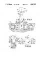
- FIG. 1shows a simplified plan view, partially sectionalized, of two interconnectable elements and a holder assembly incorporating activating means for selectively moving the locking means provided on one of said interconnectable elements.
- FIG. 2a sectional view of the cooperating cross-sections of the projection and projection receiving socket provided in the interconnected elements.
- FIG. 2Ais a plan view of the holder of FIG. 1.
- FIGS. 2B and 2Cshow sectional views of other preferred activator arrangements alternative to that shown in FIG. 1.
- FIGS. 3A through 3Gshow sectional views of the conforming cross-sections of the interfitted elements of FIG. 1.
- FIG. 4s an exploded perspective view of the locking ends of locking members and cooperating recesses provided in the element for interconnection with the element having the locking members.
- FIG. 1shows a robotics subsystem comprised of a holder assembly 20 for holding an element assembly 40 for interconnection with an interfitting element assembly 60.
- element 60may be coupled to a robotic device, for example, of the type which is capable of experiencinglinear movement in mutually perpendicular directions and which is further capable of moving element 60 at its upper end through mutually perpendicular rotational directions such as, for example, through a universal joint or the like.
- the lower end of element 60is provided with an interfitting projection 60a and a locking element receiving recess 60b as shown, for example, in FIG. 1.
- Element 60may be provided with lines 61, 63, and 65 which may, for example, respectively provide mechanical, pneumatic and electrical lines for interconnection with like lines 41, 43 and 39 provided in element 40 when they are interfitted in the manner shown in FIG. 2.
- Element 40may, for example, be an intermediate element for connection to asubsequent element or an end type element for performing an operation such as manipulation (i.e. picking up and dropping off), heating, spraying or other like pressurizing operation or for a mechanical rotational operationsuch as rotating the tip of a screw driver, socket wrench or other similar tool.
- manipulationi.e. picking up and dropping off
- heatingi.e. spraying or other like pressurizing operation
- a mechanical rotational operationsuch as rotating the tip of a screw driver, socket wrench or other similar tool.
- Element 40may be an intermediate element such as a universal joint for providing the robotic device with an additional swingable operation wherein still another element may be connected to intermediate element 40 and electrically, mechanically or pneumatically powered by one of the lines 41, 43, 39.
- Element 40is provided with an end 40a which may be the manipulator end forholding (and/or releasing), heating, spraying or other like operations.
- a pair of arms 42, 42bare provided on element 40 near the upper end thereofand swingably mount a pair of locking arms 44, 46 respectively by means of pins 42c, 42d.
- Arms 44, 46are each provided with a locking projection 44a, 46a at their upper ends and with an activating portion 44b, 46b at their lower ends.
- a torsion spring 45, 47is arranged about each pin 42c, 42d, the ends 45a, 45b, and 47a, 47b engage pins 59, 59b and 61a, 61b to normally respectively urge arms 44 and 46 clockwise and counter clockwise about the pins 42c, 42d.
- Holder 20is provided with a central cavity 22 (note also FIG. 2A) for receiving the main body of element 40 and is provided with communicating cavity portions 24a, 24b for respectively receiving the locking arms 44, 46 and the activating pins 29, 31 of activating devices 28, 30 which are arranged within cavities 26a and 26b of holder 20.
- Activating devices 28 and 30may, for example, be electric relays which operate activating pins 29 and 31 coupled to the armatures of relays 28 and 30.
- the free ends of activating pins 29 and 31respectively engage surfaces 44b, 46b of arms 44and 46 for selectively moving the arms 44 and 46 between the locking and unlocking positions.
- the devices 28 and 30may be operated by mechanical or pneumatic means, if desired.
- the free ends of the activatorsmay be tapered to guidingly receive the similarly tapered edge of the locking arm.
- FIG. 2Bwhichshows the activating pin 31 having a tapered slot 31a for receiving the tapered portion 46b-1 of the surface 46b of arm 46.
- Activator pin 29 and surface 44b of arm 44may be arranged in a similar fashion.
- activator pin 31may be provided with a tapered end 31a adapted to be guidingly received within the tapered slot 46b-1 of the lower end 46b of locking arm 46.
- slot 46b-1 shown in FIG. 2Cmay be an elongated slot or a circular slot forrespectively receiving either an elongated tapered portion 31a or a truncated conical-shaped portion 31a of activator pin 31. If desired, other alternative arrangements may be employed.
- the central cavityis preferably designed so that the lower end 40a of element 40 engages surface -. 22a to properly position the surfaces 44b, 46b of arms 44 and 46 for respective engagement by the ends of activator pins 29 and 31.
- Elements 40 and 60may be interengaged and locked by moving element 60, which was previously connected to the robotic device by means not shown, into axial alignment with element 40.
- the projection 60ahas a cross-section which preferably conforms to the cross-section of opening 40b.
- the conforming cross-sectionsmay be circular or may be non-circular such as oval shown in FIG. 3B, polygonal shown in FIG. 3C, rectangular shown in FIG. 3D, or square shown in FIG. 3E.
- the interlocking arrangementmay be comprised of a continuous groove 60b provided in member 60 for receiving the projections 44a, 46a (FIG.
- the projection arrangement of either FIG. 1 or FIG. 4may be employed with any of the cross-sectional arrangements shown in FIG. 3A through FIG. 3E.
- the robotics device to which element 60 is coupledmay be provided with rotational means for rotating element 60 about its longitudinal axis 60c in order to be assured that element 60 is properly aligned with element 40to assure that the proper interconnections be made, for example, between the lines 61, 63, 65 and 41, 43, 39 as shown in FIG. 2.
- Thismay accomplished in a variety of ways such as, for example, by providing a projection 60a-1 and a cooperating recess 40b-1 to permit the of members 40 and 60 in only one orientation, as shown in FIG.
- a projection 60dmay be provided on element 60 having a reflective surface 60e for cooperation with a light source 70 anda sensor 72 where light source 70 may emit light of a predetermined wavelength and sensor 72 may detect the presence of only light of said predetermined wavelength which occurs only when the reflective surface 60dis properly positioned over the elements 70 and 72.
- the inclination of reflector surface 60emay be such as to assure that light emitted from source 70 will be reflected at an angle appropriate to be received by sensor 72.
- relays 28 and 30are energized to urge activator pins 29 and 31 in the direction of arrows A-1, A-1 shown in FIG. 2A to urge the bottom ends of locking arms 44 and 46 inwardly thereby urging the projections 44a and 46a outwardly.
- Element 60is then moved into alignment with element 40 and is lowered into element 40 so that projection 60a enters, into recess 40b.
- the top portionof recess 40bmay be provided with a bevel or taper as shown at 40d and thelower end of projection 60a may be bevelled or tapered as shown at 60f in order to aid in the insertion of projection 60a into recess 40b.
- the element 60is preferably properly positioned within the element 40 when shoulders 60g and 40e are in engagement.
- a sensor 75may be provided alongshoulder 60g and mechanically, electrically, optically or pneumatically connected to the robotics device to indicate when the elements are in proper position (FIG. 2) or alternatively provided at the end of projection 60a as at 75'.
- a sensor 78may be provided in side wall 24a-1 which is engageableby the free end of arm 44 when relay devices 28 and 30 are de-energized (FIG. 1).
- Sensor 78is preferably arranged to-be engaged by arm 44 only when its projection 44a is properly entered into locking recess 60b, thereby assuring proper interlocking between elements 40 and 60. In the event of improper interlocking, the lower end of arm 44 will not swing outsufficiently to activate sensor 78, which may be of the optical, magnetic, pneumatic, mechanical, or other type sensor.
Landscapes
- Engineering & Computer Science (AREA)
- Robotics (AREA)
- Mechanical Engineering (AREA)
- Manipulator (AREA)
Abstract
Description
Claims (31)
Priority Applications (1)
| Application Number | Priority Date | Filing Date | Title |
|---|---|---|---|
| US06/924,040US4867595A (en) | 1986-10-28 | 1986-10-28 | Coupling method and apparatus for use with robotic devices and the like |
Applications Claiming Priority (1)
| Application Number | Priority Date | Filing Date | Title |
|---|---|---|---|
| US06/924,040US4867595A (en) | 1986-10-28 | 1986-10-28 | Coupling method and apparatus for use with robotic devices and the like |
Publications (1)
| Publication Number | Publication Date |
|---|---|
| US4867595Atrue US4867595A (en) | 1989-09-19 |
Family
ID=25449626
Family Applications (1)
| Application Number | Title | Priority Date | Filing Date |
|---|---|---|---|
| US06/924,040Expired - Fee RelatedUS4867595A (en) | 1986-10-28 | 1986-10-28 | Coupling method and apparatus for use with robotic devices and the like |
Country Status (1)
| Country | Link |
|---|---|
| US (1) | US4867595A (en) |
Cited By (14)
| Publication number | Priority date | Publication date | Assignee | Title |
|---|---|---|---|---|
| US5136196A (en)* | 1991-06-04 | 1992-08-04 | Megamation Incorporated | Umbilical release mechanism |
| US5167464A (en)* | 1991-10-07 | 1992-12-01 | The United States Of America As Represented By The Administrator Of The Natoinal Aeronautics And Space Administration | High-repeatability, robot friendly, ORU interface |
| US5326186A (en)* | 1992-12-14 | 1994-07-05 | The United States Of America As Represented By The Administrator Of The National Aeronautics And Space Administration | Robot friendly probe and socket assembly |
| US5352104A (en)* | 1991-10-15 | 1994-10-04 | Kabushiki Kaisha Kobe Seiko Sho | Post-cure inflator |
| US5386621A (en)* | 1993-08-16 | 1995-02-07 | Ford Motor Company | Flexible assembly cell |
| US5692790A (en)* | 1994-07-18 | 1997-12-02 | Ford Motor Company | System for locating an end effector of a robot relative to a part |
| US6129478A (en)* | 1996-07-24 | 2000-10-10 | Quest Diagnostics Incorporated | Locking mechanism |
| US6478503B1 (en)* | 2001-06-26 | 2002-11-12 | Pao-Hsien Cheng | Locking device for a detachable handrest of a stroller |
| WO2003033220A1 (en)* | 2001-10-19 | 2003-04-24 | Abb Ab | An apparatus and procedure for attachment of a tool on a tool attachment plate on an industrial robot |
| US9156652B1 (en)* | 2014-01-07 | 2015-10-13 | Alan R. Warboys | Speedy winch adapter |
| US9963230B2 (en)* | 2016-01-11 | 2018-05-08 | The Procter & Gamble Company | Aerial drone cleaning device and method of cleaning a target surface therewith |
| US20180126447A1 (en)* | 2014-07-09 | 2018-05-10 | The Boeing Company | Utility Fixture for Creating a Distributed Utility Network |
| CN112499283A (en)* | 2020-11-27 | 2021-03-16 | 合肥浩普智能装备科技有限公司 | Clamping arm for palletizing robot |
| JP2021079519A (en)* | 2019-11-22 | 2021-05-27 | セイコーエプソン株式会社 | Robot system and tool exchange method |
Citations (2)
| Publication number | Priority date | Publication date | Assignee | Title |
|---|---|---|---|---|
| US1876103A (en)* | 1928-12-10 | 1932-09-06 | Wired Radio Inc | Water cooled tube assembly |
| FR69788E (en)* | 1956-03-23 | 1958-12-30 | Koppers Gmbh Heinrich | Operating devices for coke oven doors |
- 1986
- 1986-10-28USUS06/924,040patent/US4867595A/ennot_activeExpired - Fee Related
Patent Citations (2)
| Publication number | Priority date | Publication date | Assignee | Title |
|---|---|---|---|---|
| US1876103A (en)* | 1928-12-10 | 1932-09-06 | Wired Radio Inc | Water cooled tube assembly |
| FR69788E (en)* | 1956-03-23 | 1958-12-30 | Koppers Gmbh Heinrich | Operating devices for coke oven doors |
Non-Patent Citations (2)
| Title |
|---|
| Brochure entitled Quick Change Adaptors of EOA Systems Inc.* |
| Brochure entitled X Change Model 40 Product Data Sheets of Rotobics.* |
Cited By (23)
| Publication number | Priority date | Publication date | Assignee | Title |
|---|---|---|---|---|
| US5136196A (en)* | 1991-06-04 | 1992-08-04 | Megamation Incorporated | Umbilical release mechanism |
| EP0517061A1 (en)* | 1991-06-04 | 1992-12-09 | Megamation Incorporated | Umbilical release mechanism |
| US5167464A (en)* | 1991-10-07 | 1992-12-01 | The United States Of America As Represented By The Administrator Of The Natoinal Aeronautics And Space Administration | High-repeatability, robot friendly, ORU interface |
| US5352104A (en)* | 1991-10-15 | 1994-10-04 | Kabushiki Kaisha Kobe Seiko Sho | Post-cure inflator |
| US5326186A (en)* | 1992-12-14 | 1994-07-05 | The United States Of America As Represented By The Administrator Of The National Aeronautics And Space Administration | Robot friendly probe and socket assembly |
| US5386621A (en)* | 1993-08-16 | 1995-02-07 | Ford Motor Company | Flexible assembly cell |
| US5692790A (en)* | 1994-07-18 | 1997-12-02 | Ford Motor Company | System for locating an end effector of a robot relative to a part |
| US6129478A (en)* | 1996-07-24 | 2000-10-10 | Quest Diagnostics Incorporated | Locking mechanism |
| US6478503B1 (en)* | 2001-06-26 | 2002-11-12 | Pao-Hsien Cheng | Locking device for a detachable handrest of a stroller |
| US20050055135A1 (en)* | 2001-10-19 | 2005-03-10 | Mattias Lindevall | Apparatus and procedure for attachment of a tool on a tool attachment plate on an industrial robot |
| WO2003033220A1 (en)* | 2001-10-19 | 2003-04-24 | Abb Ab | An apparatus and procedure for attachment of a tool on a tool attachment plate on an industrial robot |
| US9156652B1 (en)* | 2014-01-07 | 2015-10-13 | Alan R. Warboys | Speedy winch adapter |
| US10835947B2 (en) | 2014-07-09 | 2020-11-17 | The Boeing Company | Method for building an assembly fixture for supporting a fuselage assembly |
| US20180126447A1 (en)* | 2014-07-09 | 2018-05-10 | The Boeing Company | Utility Fixture for Creating a Distributed Utility Network |
| US10737316B2 (en) | 2014-07-09 | 2020-08-11 | The Boeing Company | Mobile platforms for performing operations along an exterior of a fuselage assembly |
| US10744554B2 (en)* | 2014-07-09 | 2020-08-18 | The Boeing Company | Utility fixture for creating a distributed utility network |
| US10960458B2 (en) | 2014-07-09 | 2021-03-30 | The Boeing Company | Mobile platforms for performing operations inside a fuselage assembly |
| US10974311B2 (en) | 2014-07-09 | 2021-04-13 | The Boeing Company | Metrology-based system for operating a flexible manufacturing system |
| US11724305B2 (en) | 2014-07-09 | 2023-08-15 | The Boeing Company | Autonomous flexible manufacturing system for building a fuselage |
| US12290852B2 (en) | 2014-07-09 | 2025-05-06 | The Boeing Company | Autonomous flexible manufacturing system for building a fuselage |
| US9963230B2 (en)* | 2016-01-11 | 2018-05-08 | The Procter & Gamble Company | Aerial drone cleaning device and method of cleaning a target surface therewith |
| JP2021079519A (en)* | 2019-11-22 | 2021-05-27 | セイコーエプソン株式会社 | Robot system and tool exchange method |
| CN112499283A (en)* | 2020-11-27 | 2021-03-16 | 合肥浩普智能装备科技有限公司 | Clamping arm for palletizing robot |
Similar Documents
| Publication | Publication Date | Title |
|---|---|---|
| US4867595A (en) | Coupling method and apparatus for use with robotic devices and the like | |
| US5360249A (en) | Multifunctional end effectors | |
| KR102464257B1 (en) | Rapid Robot Arm Tool Changer | |
| US4604787A (en) | Tool changer for manipulator arm | |
| US4664588A (en) | Apparatus and method for connecting and exchanging remote manipulable elements to a central control source | |
| US5018266A (en) | Novel means for mounting a tool to a robot arm | |
| US5044063A (en) | Robotic tool change mechanism | |
| EP3983181B1 (en) | Tool changer for collaborative robots, a robot tool changer system and a method for connecting a tool to a robot arm | |
| EP0154227B1 (en) | Exchange system and method for connecting, and/or exchanging remote elements to a central control source | |
| US9144909B2 (en) | Defense related robotic systems | |
| EP0508598B1 (en) | Tool fastening apparatus for industrial robots | |
| CN100354070C (en) | Tool change apparatus | |
| US20060232086A1 (en) | Robot handling system provided with robot hand | |
| US4781519A (en) | End effector tools | |
| US12151366B2 (en) | Separable robotic interface | |
| US5083352A (en) | Tool changing device for robot | |
| CN112959348A (en) | Electrically-driven steel ball locking type robot terminal quick-change device | |
| CN110682296A (en) | Replacement tool library and its working method for emergency disposal operations of explosion-proof robots | |
| US5219318A (en) | Spline screw autochanger | |
| US4941577A (en) | Portable robotic tool rack | |
| CN113681590A (en) | A modular robot docking device and docking method | |
| US5074699A (en) | Disengaging ball joint | |
| KR102333916B1 (en) | Tool changing system of robot manipulator | |
| EP0638396B1 (en) | A rapid attachment device for a manipulator head | |
| KR102384897B1 (en) | Automation system utilizing articulated robot |
Legal Events
| Date | Code | Title | Description |
|---|---|---|---|
| AS | Assignment | Owner name:MEGAMATION, P.O. BOX 2328, PRINCETON, NJ 08543 A C Free format text:ASSIGNMENT OF ASSIGNORS INTEREST.;ASSIGNOR:HOFFMAN, BRIAN D.;REEL/FRAME:004630/0486 Effective date:19861021 Owner name:MEGAMATION, A CORP OF NJ,NEW JERSEY Free format text:ASSIGNMENT OF ASSIGNORS INTEREST;ASSIGNOR:HOFFMAN, BRIAN D.;REEL/FRAME:004630/0486 Effective date:19861021 | |
| AS | Assignment | Owner name:MEGAMATION INCORPORATED, A CORP. OF NJ, NEW JERSEY Free format text:RE-RECORD OF AN INSTRUMENT RECORDED OCT. 28, 1986 AT REEL 4630, FRAME 486, TO CORRECT THE NAME AND HABITAT OF THE ASSIGNEE;ASSIGNOR:HOFFMAN, BRIAN D.;REEL/FRAME:005075/0157 Effective date:19861021 | |
| FEPP | Fee payment procedure | Free format text:PAYOR NUMBER ASSIGNED (ORIGINAL EVENT CODE: ASPN); ENTITY STATUS OF PATENT OWNER: SMALL ENTITY | |
| FPAY | Fee payment | Year of fee payment:4 | |
| LAPS | Lapse for failure to pay maintenance fees | ||
| FP | Lapsed due to failure to pay maintenance fee | Effective date:19930919 | |
| FPAY | Fee payment | Year of fee payment:8 | |
| AS | Assignment | Owner name:RANKIN CORPORATION, PENNSYLVANIA Free format text:ASSIGNMENT OF ASSIGNORS INTEREST;ASSIGNOR:MEGAMATION INCORPORATED;REEL/FRAME:010461/0409 Effective date:19991207 | |
| STCH | Information on status: patent discontinuation | Free format text:PATENT EXPIRED DUE TO NONPAYMENT OF MAINTENANCE FEES UNDER 37 CFR 1.362 |