US4865582A - Disposable transdermal drug applicators - Google Patents
Disposable transdermal drug applicatorsDownload PDFInfo
- Publication number
- US4865582A US4865582AUS07/169,385US16938588AUS4865582AUS 4865582 AUS4865582 AUS 4865582AUS 16938588 AUS16938588 AUS 16938588AUS 4865582 AUS4865582 AUS 4865582A
- Authority
- US
- United States
- Prior art keywords
- electrically conductive
- areas
- substrate
- drug
- conductive
- Prior art date
- Legal status (The legal status is an assumption and is not a legal conclusion. Google has not performed a legal analysis and makes no representation as to the accuracy of the status listed.)
- Expired - Lifetime
Links
Images


Classifications
- A—HUMAN NECESSITIES
- A61—MEDICAL OR VETERINARY SCIENCE; HYGIENE
- A61N—ELECTROTHERAPY; MAGNETOTHERAPY; RADIATION THERAPY; ULTRASOUND THERAPY
- A61N1/00—Electrotherapy; Circuits therefor
- A61N1/02—Details
- A61N1/04—Electrodes
- A61N1/0404—Electrodes for external use
- A61N1/0408—Use-related aspects
- A61N1/0428—Specially adapted for iontophoresis, e.g. AC, DC or including drug reservoirs
- A61N1/0432—Anode and cathode
- A61N1/044—Shape of the electrode
- A—HUMAN NECESSITIES
- A61—MEDICAL OR VETERINARY SCIENCE; HYGIENE
- A61N—ELECTROTHERAPY; MAGNETOTHERAPY; RADIATION THERAPY; ULTRASOUND THERAPY
- A61N1/00—Electrotherapy; Circuits therefor
- A61N1/02—Details
- A61N1/04—Electrodes
- A61N1/0404—Electrodes for external use
- A61N1/0408—Use-related aspects
- A61N1/0428—Specially adapted for iontophoresis, e.g. AC, DC or including drug reservoirs
- A61N1/0432—Anode and cathode
- A61N1/0436—Material of the electrode
- A—HUMAN NECESSITIES
- A61—MEDICAL OR VETERINARY SCIENCE; HYGIENE
- A61N—ELECTROTHERAPY; MAGNETOTHERAPY; RADIATION THERAPY; ULTRASOUND THERAPY
- A61N1/00—Electrotherapy; Circuits therefor
- A61N1/02—Details
- A61N1/04—Electrodes
- A61N1/0404—Electrodes for external use
- A61N1/0408—Use-related aspects
- A61N1/0428—Specially adapted for iontophoresis, e.g. AC, DC or including drug reservoirs
- A61N1/0448—Drug reservoir
Definitions
- This inventionrelates to disposable as well as replenishable transdermal drug applicators which are electrically powered, and to methods for making such constructions A complete electrical circuit is made through the skin once the drug applicator is adhered thereto, whereby at least one physico/chemical mass transfer phenomenon takes place causing the drug or medicament to migrate through the skin.
- FIG. 1is a perspective view, partially cut away, so as to illustrate the innards of a self-contained drug applicator of the invention
- FIG. 2is a longitudinal cross-sectional view of the drug applicator of FIG. l, and also illustrating in exploded view a reusable power supply which may be provided with a programmable control and wrist watch mounting;
- FIG. 2Ais a view similar to FIG. 2, but shown perspectively, in which the power supply and the programmable control are contained within a wrist watch mounting having concentric connectors;
- FIG. 3is another perspective view similar to FIG. 1, but showing an alternate construction having a pair of off-center apertures or slots for the electrical contacts made through the use of a single center aperture so as to enable the mounting of a new drug applicator to the reusable power supply in a keyed or polarized manner.
- FIGS. 4 and 5are fragmentary perspective views of typical configurations of drug electrodes/reservoirs provided on endless web substrates fed from rolled stock material, with occlusive adhesive dams separating the drug reservoirs longitudinally, as well as transversely;
- FIGS. 6 and 7respectively illustrate diagrammatically typical assemblies of drug electrodes/reservoirs forming larger reservoir means; or forming drug gradient with layers of both high and low drug concentration within reservoirs separated by a semipermeable membrane or reinforcing scrim.
- FIG. 8is a cross-sectional view of a disposable drug applicator with a separate subassemblied power source and electrical conditioning means adhesively assembled along their electrodes to any one typical drug electrode/reservoir assemblies shown in FIGS. 6-7;
- FIG. 8Ais a cross-sectional view similar to that shown in FIG. 8, but illustrating an alternate drug applicator construction in which the outer conformal cover has window means through which current induced color changes or other visual feedback information can be viewed for verification of status of the drug delivery system, such as drug delivery taking place or having been terminated.
- FIG. 9is a cross-sectional view of an alternate construction having similarly optionally replaceable drug reservoirs (electrodes/reservoirs), and with flat batteries forming a sub-assembly with electrical connections to electronic conditioning means;
- FIG. 10illustrates an endless such substrate fed from rolled stock material upon which is provided thin sheet electrodes for the flat batteries and other rolled, layered materials for forming the power-source sub-assembly shown in FIG. 9;
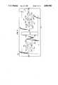
- FIG. 11illustrates a top view embodiment of the drug applicator having the end portions of the substrate folded downwardly and having a number of bottom batteries;
- FIG. 12is a cross-section taken through line 12--12 of FIG. 11;
- FIG. 13is an exploded perspective view of the drug applicator shown in FIG. 11 having fewer batteries with the elements shown in their order of assembly;
- FIG. 14is a sectional view analogous to the cross-sectional view illustrated in FIG. 12 with electrical connections between the batteries and the reservoirs extending upon a flat substrate;
- FIG. 15is a fragmented enlarged sectional view of the electrical connection shown in FIG. 14;
- FIG. 16is a sectional view of the electrical connection shown in FIG. 15 in the process of assembly;
- FIG. 17is an isolated top view of a first alternate embodiment of an electrical connection made through a substrate of the type shown in FIG. 14;
- FIG. 18is a view taken through line 18--18 in FIG. 17;
- FIG. 19is an isolated top view of a second alternate embodiment of an electrical connection made through a substrate of the type shown in FIG. 14
- FIG. 20is a view taken through line 20--20 in FIG. 19;
- FIG. 21is an isolated top view of a third alternate embodiment of an electrical connection made through a substrate of the type shown in FIG. 14;
- FIG. 22is a view taken through line 22--22 in FIG. 14.
- transdermal drug applicator 10which is adhered to the skin 11 comprising an outer cover 12 with a centrally raised portion 14 and a peripheral sealed area or lip portion 16.
- a transdermal drug applicatoris of the replaceable type having provision for connection to a reusable power supply 18 which may be, if desired, part of a wrist watch mounting having optionally a programmable control device such as more particularly described and claimed in said aforementioned earlier filed U.S. patent application, Ser. No. PCT/US85/01075, filed June 10, 1985.
- Power supply 18comprises a suitable disc battery 20 having electrodes or terminals on opposite sides thereof.
- One battery electrodeis electrically connected to current conditioning or electronic conditioning means 22 and by means of suitable snap-on or other type of mechanical connectors (silver-plated Velcro connections manufactured by Velcro Corporation of America) or by conductive and reusable adhesives; and the battery electrodes are in turn connected to conductors 24, 24' extending from drug reservoirs 26, 28, which are also indicated as reservoirs B and C, respectively.
- the conductors 24, 24'are flexible, suitably conductive surfaces or coatings on a flexible plastic substrate 30 which is non-conductive, impermeable, stable and otherwise compatible with drugs, adhesives, the skin and any other materials from which the device is fabricated.
- Each conductor 24, 24' with its substrate 30forms a seamless, one-piece, folded member.
- the plastic substrate 30 and conductive surfacesbring the electrical contacts 24, 24' to the top side of the drug applicator where the electrical connections are to be made with the reusable power supply 18.
- the adhesive coating 32 on the inside (and topside) of the plastic substrate 30secures together the mating surfaces as well as the overlapping edge or end 34 which is provided with a suitable slot or aperture 36 representing a nest or well area for receiving the power supply 18 and its electrical connectors.
- a small peripheral clearing 38 about the aperture 36represents an insulating guard area to preclude any possibility of shorting out.
- the lower electrode 40 and upper electrode 42 of the batterydirectly or indirectly make electrical contact with conductors 24, 24'.
- Suitable insulating material 44surrounds the current or electronic conditioning means 22 and suitable insulating material "A", which forms the dam separating the drug reservoirs 26, 28 and provides the end seals for not only the side of longitudinal edges but also for the transverse edges of the transdermal drug applicator.
- Conformable cover 12protects the entire device and may be suitably of a skin tone or color and the like appearance.
- the coverneed not be conductive as the lip portion merely acts as a peripheral seal and not a return electrode.
- the inventionis also applicable to drug applicators of the "matted" frame construction where the lip portion acts as the return or inactive electrode. In such case, then the conformable cover must also be conductive.
- Electro-kinetic mass transfer processesrequire an electric power source, and in the case of electrophoresis an ionized drug migrates from the drug applicator patch through the skin and into the blood stream, whereas in the case of electro-osmosis, a fluid carrier, such as water is likewise transported across the skin and into the blood stream carrying along with it any and all dissolved constituents (ionized drugs or otherwise). Either or both of these two physiochemical phenomena may jointly work together or independently in transdermally carrying a drug or drugs across the skin in a desired dosage release and/or relatively steady pattern.
- the application or an electric field across the skingreatly enhances the skin permeability to various drugs.
- a suitable release liner 48Prior to the attachment to the skin, a suitable release liner 48 is removed leaving the two drug reservoirs, insulating dam and peripheral seals free to adhere to the skin.
- the power supply 18is supported by a like plastic substrate 50 which is in turn suitably adhesively secured by adhesive 51 to a small conformal cover 52 which neatly covers over and seals off the apertured area where the electrical connections are made. This ensures that the device can be worn at all times; such as in the rain or in the shower or bath.
- the reusable power supply 18may be part of a wrist watch 54, as shown in FIG. 2A, having a programmable computer with concentric conductive adhesive connectors 40, 42, such as previously disclosed in said earlier patent filing with like electrical connections and mechanical securement being provided where needed to achieve such packaged construction
- the main difference between the disposable drug applicators shown in FIGS. 2 and 2Ais that the conformal cover means 12, of FIG. 2A is coated with an adhesive layer 13. Such adhesive layer 13 allows removal of the drug applicator and replacement same as adhesive 51 in FIG. 2.
- FIG. 3simply adds the feature of an optimal tab 56 for the release liner or paper 48, and the use of offset apertures 58 and 60 for mating with the conductive adhesive contacts at the bottom of battery 20 and the extended substrate 50 which may be offset in a manner to provide just side to side connection in lieu of concentric or symmetric connections
- the drug reservoirsmay be suitable gel layers which can be rolled or otherwise applied to webbed substrate 48, discussed previously, fed from endless rolled sheet material while being separated between reservoirs and about their extreme edges by applied occlusive adhesive dams.
- the damsare identified by the Letters A and the drug reservoirs are marked with the Letters B representing negative and C representing positive.
- the "quilt" type pattern where multiple drug reservoirs are employedcan be fabricated by repetitive operative steps using a silk screen printing or transfer process.
- the substrateis coated with a suitable release agent 49, such as silicone and when the sub-assembly is combined into a complete transdermal drug applicator or patch, the substrate in effect becomes the release liner.
- FIGS. 6-7illustrate the assembly of two drug applicator sub-assemblies.
- an optional reinforcing web or vail-like material (scrim) 62may be used to reinforce the gel "drug" reservoirs.
- One embodimentuses an open cell foam which is impregnated in different areas with gel drug reservoirs surrounded by occlusive adhesive dam penetrating the same open cell foam.
- Such a structureallows the construction of a thick replaceable drug reservoir in which the gel will maintain its integrity during manufacturing, the application to and removal from human skin, as well as to the replacement of exhausted drug reservoirs
- the open cell foam webmay be suitably attached to a release liner, then provided with occlusive adhesive dams which completely penetrate the full thickness of the open cell foam, thus forming or designating the drug reservoir areas which can be subsequently filled in with their respective drug/gel mixtures.
- FIG. 7simply differs in that a semi-permeable membrane 64 is provided between the two sub-assemblies so that upon assembly, drug reservoirs are formed with areas or zones of different drug concentration or composition.
- a semi-permeable membrane 64is provided between the two sub-assemblies so that upon assembly, drug reservoirs are formed with areas or zones of different drug concentration or composition.
- Such a type of drug reservoiris noted to have significant advantages during operation of the transdermal device.
- appropriate seals 47can be provided along the semi-permeable membranes at the edges where each reservoir ends by means of heat or by other means to collapse the voids and seal the semipermeable membrane in those areas 47 where the seals are necessary.
- silicone damscould also be used as seals between zones of semi-permeable materials.
- the semi-permeable materialsmay be preimpregnated with drugs or other chemicals which might be employed.
- the disposable drug applicator 70 shown in FIG. 8comprises an optionally replaceable drug reservoir sub-assembly 72 (any one of FIGS. 4-7) and a further sub-assembly 74 for the power means and electrical conditioning means which assemblies are secured together by suitable conductive adhesives.
- Sub-assembly 74comprised essentially of battery 20 and current conditioning means 22 and associated reservoir conductors 24, 24' as best shown in FIG. 2.
- the electrical circuit running between the drug reservoirs and through the skinis a loop similar to that of FIG. 2, the only difference being the permanent nature of the battery and current/electrical conditioning means in the applicator structure rather than the reusable nature of the FIG. 2 embodiment.
- the drug reservoir sub-assembly 72may be replaced where required.
- the cover means 76is suitably provided with window means, as is shown, which allows the status of the drug applicator to be observed
- window meanswhich allows the status of the drug applicator to be observed
- Such indicator means which is observed through the window meansis more particularly described in my earlier filed U.S. Pat. application, Ser. No. 660,192, filed Oct. 12, 1984.
- the indicator means 150is electrically in series with the current conditioning means 22 and conductive surface 90 which powers drug reservoir B.
- the connections of said indicator means 150 to the current conditioning means 90 and the conductive surfaceare achieved by means of a suitable flexible conductive adhesive, as is shown at the contact joints 152 and 154.
- FIG. 9represents a like kind of disposable drug applicator 80 having an optionally replaceable drug reservoir sub-assembly 72 as illustrated in FIGS. 8-8A, and a power source or flat layered battery, as well as electrical or current conditioning means 84 sub-assembly which are secured together by suitable conductive adhesives.
- the batteryembodies sheet electrodes such as carbon (-) reference number 86 and zinc(+), reference number 88 and the drug reservoir electrodes 90, 90' which also are thin and flat.
- the battery electrodes 86, 88are adhesively connected to a plastic substrate 30.
- the webbed material in productionis preferably folded along the illustrated longitudinal fold lines, 73, 73',73",73"' (and others may be required depending upon the required number of folds) cut transversely to a predetermined size
- One carbon electrode 86 which is connected to the drug reservoir electrode 90forms a battery with the large zinc electrode 88.
- the carbon electrode 86 which is connected to electrode 90could be made as one unitary element.
- This large zinc electrode 88is electrically connected to the other carbon electrode 86 by means of the conductive adhesive strip 87 (FIG. 10) at one end thereof, and thus forms a second battery, in series with the first battery, in conjunction with the small zinc electrode 88 which is likewise electrically connected to conductive surface 134 at 87' or simply with a conductive adhesive strip similar to 87.
- a suitable current or other electronic conditioning means 84is secured by a conductive adhesive 130 to one of the drug electrode conductive surfaces 90' having a flexible plastic substrate 30 and is also electrically connected to one of the battery electrodes, shown at 100 by means of an optional conductive indicator 150'.
- a window meanssuch as a transparent area 156 of the cover 12 or an opening in said cover allows the viewing of an optional indicator 150'. In such case, the indicator 150' replaces the conductive connector.
- the last battery electrode, shown at 88is electrically connected to the other drug electrode conductive surface 90 to form a complete electrical loop between the two drug reservoirs and through the skin.
- a suitable battery electrode element 131 impregnated with a gelled battery electrolyteis inserted between the carbon and zinc electrodes prior to folding, and the peripheries of the battery compartments are suitably sealed at 132 to prevent electrolyte leakage.
- the drug reservoirsare also optionally removable if desired, as was shown in FIGS. 8-8A.
- some adhesives employedmay also be conductive while in other instances it is inherent that the adhesive has no other function than to secure together objects so it need not necessarily be conductive and in some cases it must not be conductive or a short circuit would occur.
- the voltage of the batterywill determine the numbers of carbon and zinc electrodes required, and such voltage can vary depending upon the applications. Although only carbon/zinc batteries are illustrated, other type battery cells could be made in a similar manner.
- FIGS. 6 and 7describe the replaceable drug reservoir which is employed by the end user (patient, nurse or doctor) by peeling off the release liner 48, applying the drug reservoir to the area 90, 90' of power supply applicator construction which results in the device shown in FIG. 9 which then could be applied on the human skin after peeling off the release liner 48.
- the battery lifewill be sufficient for the use of the applicator of FIG. 9 with a predetermined number of "refills" (similar to FIGS. 6 or 7) when marketed together in kit form.
- the samewould hold true for all the other alternate constructions and embodiments of the invention.
- the power supply and the current regulating or electronic conditioning meansis designed to perform only for a predetermined number of "refills" so as to guarantee medical supervision for each set of treatments (kit).
- a current limiting resistorin series with the battery can be manufactured by controlling the resistance of the conductive surfaces.
- Such usewould make the device fail safe and could provide current regulation in addition to or instead of solid state conditioning means 22 of FIG. 8. Therefore, if the current conditioning means 22 of FIG. 8 short circuits this resistor will limit the current to a safe value or level.
- Drug applicator 200includes a pair of optionally replaceable drug reservoirs B and C, and a power source, such as twelve button batteries 202A-L, all enclosed by an outer cover 204, which is preferably aluminized.
- Button batteries 202A-Lare arranged in two units 206 and 208, each including five batteries, namely, batteries 202A-E and 202F-L, respectively.
- Battery unit 206is located proximately above reservoir B, which is negative in charge, and battery unit 206 is located proximately above reservoir C, which is positive in charge.
- Batteries 202A-Lcan vary in number and voltage in accordance with a particular design for a particular drug or drugs contained in the reservoirs. Each battery illustrated is typically 1.5 volts, but the system can include more or fewer batteries each having a lesser or greater voltage. Alternatively, flat batteries typically approximately 1.5 mm in thickness can be used in lieu of the button batteries. Button batteries 202A-L have vertically opposed terminals. The charges of the topside terminals of button batteries 202A-L are shown in FIG. 1.
- a flexible plastic substrate 210, such as "Mylar"has electroconductive coating 212, preferably an electroconductive graphite paint, applied to one side and an adhesive layer 214 applied to the opposite side.
- Substrate 210is non-conductive, impermeable, stable, and compatible with drugs, adhesives, the skin, and materials from which drug applicator 200 is fabricated.
- Substrate 210has end portions 216B and 216C which are each underfolded once in an outward, or downward, direction as viewed in FIG. 10, toward reservoirs B and C so that a topside and a bottomside portion is at each end with conductive paint 212 being in electrical contact with the inner side of reservoirs B and C at end portions 216B and 216C.
- Conductive paint 212covers two separate areas of substrate 210 each in contact with end portions 216B and 216C so that there is no direct electrical connection between reservoirs B and C by way of end portions 216B and 216C.
- Adhesive layer 214adheres to adhesive layer 214 at the end portions 216B and 216C.
- Conductive paint 212which covers the entire under-surface of end portions 216B and 216C of substrate 210, follows the folded contour of substrate 210 inwardly, or upwardly, so that paint 212 is on the top surface side of the main portion of substrate 210 so that paint 212 is in electrical contact with the bottomside terminals of batteries 202A-L.
- paint 212is configured as printed circuits 218B and 218C, shown in FIG. 11, joining the positive and negative bottomside terminals of the batteries.
- Printed circuits 220B and 220Cwhich connect in series the positive and negative topside terminals of batteries 202A-L at battery units 206 and 208, are placed on the underside of a stiff plastic sheet 222, which extends over all batteries 202A-L.
- a current conditioner 224is positioned proximate battery unit 208 is connected in series with batteries 202A-L by a printed circuit 226 on the undersurface of plastic sheet 222.
- Electroconductive adhesive paste drops 228are preferably used to ensure good electrical connections between the terminals of the batteries and printed circuits 218B and 218C and 220B and 220C. Electroconductive paste drops 228 are also used at the opposed sides of current conditioner 224. An electrical circuit thus exists between reservoirs B and C through the skin upon placement of applicator 200 upon the skin and through batteries 202A-L and current conditioner 224.
- a pair of perforated plastic liners 230A and 230Bare preferably placed on either side of batteries 202A-L primarily to inhibit any spreading of drops 228. Perforations in liners 230 provide access for drops 228.
- a spacersuch as foam spacer 232, is preferably positioned between the pair of liners 230A and 230B.
- a heat sealable plastic liner 234is positioned on the underside of applicator 200 and is connected to the periphery of cover 204.
- a skin adhesive 236is placed on the underside of liner 234.
- a removable release liner(not shown) is ordinarily placed on the underside of liner 234 and is removed prior to use of the applicator.
- Sealed edges in the form of sealed side walls 238are disposed about the periphery of reservoirs B and C in order to prevent passage of the drug or drugs from the reservoirs.
- the sealed side walls 238may be formed, if desired, by heat sealing through liner 234 and through the drug reservoir material to substrate 210. Alternately, walls 238 can be formed by using a suitable material such as a silicon adhesive to seal the peripheral reservoir edges and to affix liner 234 to drug reservoirs B and C.
- Drug applicator 200can be assembled in steps from the components described above. These components are illustrated in FIG. 13 in an exploded perspective view of a drug applicator 242 analogous to drug applicator 200.
- the assembly of applicator 242comprises the following steps:
- Short indentations 254 and 256 of conductive paint 212extend onto the left and right topside ends, respectively, of substrate 210 where batteries 246A and 246C are to be located.
- a printed circuit 258 of conductive paint, or ink, of the same material as conductive paint 212extends between the areas of placement of batteries 248B and 248C in order to connect the terminals of current conditioner 224.
- a pair of cutouts 240B that are part of breathing windows 240are formed in the center area of substrate 210;
- Liner 210Ahas three holes 262 for electroconductive drops 228 for batteries 248A-C and a hole 264 for the electroconductive drop 228 for one end of current conditioner 224 and a pair of cutouts 240C that are a part of breathing windows 240. Nesting holes 262 and 264 are aligned with electroconductive paste drops 228;
- a spacerpreferably a foam spacer 232, onto liner 230A.
- Foam spacer 232forms three nesting holes 268 for receiving batteries 248A-C, a nesting hole 270 for receiving current conditioner 224, and a pair of cutouts 240D that are a part of breathing windows 240. Holes 268 and 270 are placed into nesting alignment with the batteries and current conditioner;
- electroconductive adhesive paste drops 274onto the top side terminals of batteries 248A-C; and placing electroconductive adhesive paste drops 274 into electrical contact with the top side terminals of batteries 248A-C; alternatively, in lieu of paste drops 274 an electroconductive paste can be coated on liner 210 and the paste can be die cut with the coating removed before the assembly process so as to isolate electroconductive paste units such as disks, which may be employed in the practice of the invention;
- Liner 230Bforms three holes 278 for electromagnetic drops 274 for the topside terminals of batteries 248A-C, a hole 280 for the electromagnetic drop 274 for current conditioner 224, and a pair of cutouts 240E that are a part of breathing windows 240;
- Flat layered batteries such a batteries 86, 88 illustrated in FIGS. 9 and 10may be substituted for button batteries 202A-L illustrated in FIGS. 11 and 12 and button batteries 248A-C illustrated in FIG. 13.
- the production method illustrated in FIG. 10can be used for applicators 200 and 242.
- Reservoirs B and Care enclosed at their sides by heat-sealed walls 238. Either one or both reservoirs may be used, that is, a non-drug electrode may be substituted for either reservoir.
- a pair of breathing windows 240 that extend transversely through the entire drug applicator 242 between battery units 206 and 208provide a passage for evaporated sweat that may form on the skin.
- the two battery units 206 and 207 in FIGS. 11 and 12 and the two battery units 250 and 252 in FIG. 13may be one battery unit positioned on the side of either drug reservoir B or C.
- FIG. 14illustrates transdermal drug applicator 300 having the same arrangement of elements as described for dug applicator 200 described earlier in relation to FIG. 12 except for a flat, flexible substrate 302 made of a plastic such as "Mylar" or other similar material.
- Substrate 210is non-conductive, impermeable to the passage of liquid, stable, and compatible with drugs, adhesives, skin, and materials from which drug applicator 300 is fabricated.
- Substrate 302has top and bottom electroconductive coatings 304A and 306A applied to the top and bottom surfaces, respectively, of substrate 302 in the vicinity of reservoir B and further has top and bottom electroconductive coatings 304B and 306B applied to the top and bottom surfaces, respectively, of substrate 302 in the vicinity of reservoir C.
- Coatings 304A, 306A, 304B, and 306Bare preferably made of an electroconductive material such as carbon, preferably graphite.
- the graphitecan be in the form of a graphite paint.
- Top conductive coating 304Aextends to electrical connection with batteries 202A and 202F, but also is representative of top electrical conductive connections between all batteries 202A-F.
- top conductive coating 304Bextends to electrical connection with batteries 202A and 202F, but also is representative of top electrical conductive connections between all batteries 202G-K.
- Bottom coating 306Ais in electrical connection with reservoir B and bottom coating 306B is in electrical connection with reservoir C.
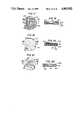
- FIG. 16illustrates an enlarged detail view of substrate 302 with top and bottom coatings 304A and 306A joined in electrical connection by top and bottom electroconductive joining strips 308 and 310, respectively.
- Top joining strip 308includes a flexible top substrate strip 312 made of the same material as substrate 302 and an electroconductive top coating strip 314 made of the same electroconductive material as coatings 304A and 306A.
- Top coating strip 314is in electrical connection with top conductive coating 304A.
- bottom joining strip 310includes a flexible bottom substrate strip 316 made of the same material as substrate 302 and an electroconductive bottom coating strip 318 made of the same electroconductive material as coatings 304A and 306A.
- Bottom coating strip 318is in electrical connection with bottom conductive coating 306A.
- Substrate 302defines a circular hole 320A, which extends transversely through substrate 302 and also through top and bottom conductive coatings 304A and 306A.
- Top and bottom joining strips 308 and 310are secured to the top and bottom coating strips 314 and 318, respectively, by top and bottom adhesives 322 and 324, respectively.
- Top and bottom joining strips 308 and 310extend into hole 320A where their respective top and bottom coating strips 314 and 318 are joined in electrical contact at a juncture preferably held together by an electrically conductive adhesive 326.
- Top and bottom joining strips 308 and 310 along with hole 320Aare the same for the electrical connection between top and bottom conductive coatings 304B and 306B at hole 320B illustrated in FIG. 14.
- FIG. 16illustrates the assembly of the electrical connection between top and bottom coating strips 312 and 314.
- Top and bottom joining strips 304 and 306are positioned spaced from top and bottom conductive coatings 304A and 306A of substrate 302 prior to the next steps of pressuring top and bottom joining strips into mutual electrical contact inside of hole 320A and into adhesive connection with top and bottom conductive coatings 304A and 306A.
- FIGS. 17 and 18illustrate another embodiment of a construction and arrangement for connecting top and bottom conductive coatings 304A and 306A into electrical contact.
- a mesh member 328is positioned over a hole 327 extending through substrate 302 and its top conductive coating 304A.
- Bottom conductive coating 306extends across hole 327.
- Mesh memberis pressed into adhesive contact with top conductive coating 304A around hole 320A and is further pressed into hole 320A into adhesive contact with bottom conductive coating 306A.
- Mesh member 328has a plurality of mesh holes which are filled with a conductive material 330, such a carbon, which can be graphite, for example.
- top and bottom conductive coatings 304A and 306Aare electrically connected by means of conductive material 330. Electrical connection of top and bottom conductive coatings 304B and 306B through hole 304B is of the same arrangement and construction described.
- FIGS. 19 and 20illustrate yet another embodiment of a construction and arrangement for connecting top and bottom conductive coatings 304A and 306A into electrical contact.
- substrate 302 and top conductive coating 304Aform a plurality of small transverse holes 332 over a cylindrical volume 334.
- Holes 332are filled with a conductive material 336, such as carbon, which can be graphite, which electrically connects top and bottom conductive coatings 304A and 306A.
- Electrical connection of top and bottom conductive coatings 304B and 306Bis of the same construction and arrangement described.
- FIGS. 21 and 22illustrate yet another embodiment of a construction and arrangement for connecting top and bottom conductive coatings 304A and 306A into electrical contact.
- substrate 302 and top conductive coating 304Aform a plurality of small transverse slots 338 over a cylindrical volume 340, with slots 338 being of different lateral dimensions so as to stay within the dimensions of volume 340.
- Slots 338are filled with a conductive material 342, such as carbon, which can be graphite, which electrically connects top and bottom conductive coatings 304A and 306A.
- Electrical connection of top and bottom conductive coatings 304B and 306Bis of the same construction and arrangement described.
Landscapes
- Health & Medical Sciences (AREA)
- Engineering & Computer Science (AREA)
- Life Sciences & Earth Sciences (AREA)
- Biomedical Technology (AREA)
- Nuclear Medicine, Radiotherapy & Molecular Imaging (AREA)
- Radiology & Medical Imaging (AREA)
- Bioinformatics & Cheminformatics (AREA)
- Animal Behavior & Ethology (AREA)
- General Health & Medical Sciences (AREA)
- Public Health (AREA)
- Veterinary Medicine (AREA)
- Electrotherapy Devices (AREA)
- Media Introduction/Drainage Providing Device (AREA)
- Medicinal Preparation (AREA)
Abstract
Description
______________________________________ 385,556 4,243,052 486,902 4,325,367 588,479 4,367,745 2,493,155 4,419,091 2,267,162 4,474,570 2,784,715 4,406,658 3,163,166 4,314,554 3,289,671 4,166,457 3,547,107 4,239,052 3,677,268 4,290,878 4,008,721 4,164,226 4,141,359 4,362,645 4,239,046 4,273,135 ______________________________________
Claims (11)
Priority Applications (13)
| Application Number | Priority Date | Filing Date | Title |
|---|---|---|---|
| US07/169,385US4865582A (en) | 1987-06-05 | 1988-03-17 | Disposable transdermal drug applicators |
| AU16550/88AAU618734B2 (en) | 1987-06-05 | 1988-05-24 | Disposable and/or replenishable transdermal drug applicators |
| AT88108838TATE176873T1 (en) | 1987-06-05 | 1988-06-02 | METHOD FOR PRODUCING APPLICATORS FOR TRANSDERMAL ADMINISTRATION OF MEDICATIONS |
| EP88108838AEP0293893B1 (en) | 1987-06-05 | 1988-06-02 | A method of manufactoring a transdermal drug applicator |
| ES88108838TES2131039T3 (en) | 1987-06-05 | 1988-06-02 | PROCEDURE FOR THE MANUFACTURE OF TRANSDERMIC DRUG APPLICATORS. |
| AR88311018AAR246025A1 (en) | 1987-06-05 | 1988-06-02 | Disposable and/or replenishable transdermal drug applicators and methods of manufacturing same |
| BR8802677ABR8802677A (en) | 1987-06-05 | 1988-06-02 | PERCUTANE MEDICINE APPLICATOR AND MANUFACTURING PROCESS |
| DE3856306TDE3856306T2 (en) | 1987-06-05 | 1988-06-02 | Process for the manufacture of applicators for the transdermal administration of medicaments |
| JP63137197AJP2632367B2 (en) | 1987-06-05 | 1988-06-03 | Transdermal drug delivery device |
| KR1019880006772AKR960011033B1 (en) | 1987-06-05 | 1988-06-04 | Disposable and / or supplemental transdermal drug applicator and preparation method thereof |
| CA000568748ACA1322921C (en) | 1987-06-05 | 1988-06-06 | Disposable and/or replenishable transdermal drug applicators and methods of manufacturing same |
| AU85713/91AAU633226B2 (en) | 1987-06-05 | 1991-10-10 | Disposable transdermal drug applicators |
| JP7322340AJPH08238325A (en) | 1987-06-05 | 1995-11-16 | Apparatus for endermic administration of chemical |
Applications Claiming Priority (2)
| Application Number | Priority Date | Filing Date | Title |
|---|---|---|---|
| US07/058,527US4883457A (en) | 1983-08-18 | 1987-06-05 | Disposable and/or replenishable transdermal drug applicators and methods of manufacturing same |
| US07/169,385US4865582A (en) | 1987-06-05 | 1988-03-17 | Disposable transdermal drug applicators |
Related Parent Applications (1)
| Application Number | Title | Priority Date | Filing Date |
|---|---|---|---|
| US07/058,527Continuation-In-PartUS4883457A (en) | 1983-08-18 | 1987-06-05 | Disposable and/or replenishable transdermal drug applicators and methods of manufacturing same |
Publications (1)
| Publication Number | Publication Date |
|---|---|
| US4865582Atrue US4865582A (en) | 1989-09-12 |
Family
ID=26737714
Family Applications (1)
| Application Number | Title | Priority Date | Filing Date |
|---|---|---|---|
| US07/169,385Expired - LifetimeUS4865582A (en) | 1987-06-05 | 1988-03-17 | Disposable transdermal drug applicators |
Country Status (10)
| Country | Link |
|---|---|
| US (1) | US4865582A (en) |
| EP (1) | EP0293893B1 (en) |
| JP (2) | JP2632367B2 (en) |
| AR (1) | AR246025A1 (en) |
| AT (1) | ATE176873T1 (en) |
| AU (1) | AU618734B2 (en) |
| BR (1) | BR8802677A (en) |
| CA (1) | CA1322921C (en) |
| DE (1) | DE3856306T2 (en) |
| ES (1) | ES2131039T3 (en) |
Cited By (48)
| Publication number | Priority date | Publication date | Assignee | Title |
|---|---|---|---|---|
| US5087241A (en)* | 1990-07-24 | 1992-02-11 | Empi, Inc. | Iontophoresis electrode with reservoir and injection site |
| US5125894A (en)* | 1990-03-30 | 1992-06-30 | Alza Corporation | Method and apparatus for controlled environment electrotransport |
| US5207752A (en)* | 1990-03-30 | 1993-05-04 | Alza Corporation | Iontophoretic drug delivery system with two-stage delivery profile |
| US5284471A (en)* | 1989-09-25 | 1994-02-08 | Becton, Dickinson And Company | Electrode and method used for iontophoresis |
| US5312326A (en)* | 1992-06-02 | 1994-05-17 | Alza Corporation | Iontophoretic drug delivery apparatus |
| US5314502A (en)* | 1990-03-30 | 1994-05-24 | Alza Corporation | Iontophoretic delivery device |
| WO1994016765A1 (en)* | 1993-01-28 | 1994-08-04 | Scientific Innovations Ltd. | Transcutaneous drug delivery applicator |
| WO1994027671A1 (en)* | 1993-05-28 | 1994-12-08 | Alza Corporation | Electrotransport agent delivery device |
| US5415629A (en)* | 1993-09-15 | 1995-05-16 | Henley; Julian L. | Programmable apparatus for the transdermal delivery of drugs and method |
| US5466217A (en)* | 1992-06-02 | 1995-11-14 | Alza Corporation | Iontophoretic drug delivery apparatus |
| US5498235A (en)* | 1994-09-30 | 1996-03-12 | Becton Dickinson And Company | Iontophoresis assembly including patch/controller attachment |
| US5573503A (en)* | 1984-10-29 | 1996-11-12 | Alza Corporation | Iontophoretic drug delivery |
| US5605536A (en)* | 1983-08-18 | 1997-02-25 | Drug Delivery Systems Inc. | Transdermal drug applicator and electrodes therefor |
| US5651768A (en)* | 1983-08-18 | 1997-07-29 | Drug Delivery Systems, Inc. | Transdermal drug applicator and electrodes therefor |
| US5746711A (en)* | 1987-01-05 | 1998-05-05 | Drug Delivery Systems, Inc. | Programmable control and mounting system for transdermal drug applicator |
| US5935598A (en)* | 1996-06-19 | 1999-08-10 | Becton Dickinson Research Center | Iontophoretic delivery of cell adhesion inhibitors |
| US5954685A (en)* | 1996-05-24 | 1999-09-21 | Cygnus, Inc. | Electrochemical sensor with dual purpose electrode |
| US5991655A (en)* | 1997-03-03 | 1999-11-23 | Drug Delivery Systems, Inc. | Iontophoretic drug delivery device and method of manufacturing the same |
| EP0783346B1 (en)* | 1994-09-30 | 1999-12-01 | Becton, Dickinson and Company | Improved iontophoretic drug delivery device |
| US6004309A (en)* | 1990-03-30 | 1999-12-21 | Alza Corporation | Method and apparatus for controlled environment electrotransport |
| US6169920B1 (en)* | 1992-06-02 | 2001-01-02 | Alza Corporation | Iontophoretic drug delivery apparatus |
| US6735470B2 (en) | 2000-05-31 | 2004-05-11 | Biophoretic Therapeutic Systems, Llc | Electrokinetic delivery of medicaments |
| US20040138646A1 (en)* | 2001-05-25 | 2004-07-15 | Thomas Walla | Device for administering a substance transdermally |
| US6792306B2 (en) | 2000-03-10 | 2004-09-14 | Biophoretic Therapeutic Systems, Llc | Finger-mounted electrokinetic delivery system for self-administration of medicaments and methods therefor |
| US6895271B2 (en) | 1998-09-15 | 2005-05-17 | Biophoretic Therapeutic Systems, Llc | Iontophoretic drug delivery electrodes and method |
| US6989275B2 (en) | 1986-04-18 | 2006-01-24 | Carnegie Mellon University | Cyanine dyes as labeling reagents for detection of biological and other materials by luminescence methods |
| US7127285B2 (en) | 1999-03-12 | 2006-10-24 | Transport Pharmaceuticals Inc. | Systems and methods for electrokinetic delivery of a substance |
| US20070129708A1 (en)* | 2005-02-01 | 2007-06-07 | Edwards Eric S | Devices, systems and methods for medicament delivery |
| US20070173913A1 (en)* | 2003-04-15 | 2007-07-26 | The General Hospital Corporation D/B/A Massachusetts General Hospital | Methods and devices for epithelial protection during photodynamic therapy |
| US20080033393A1 (en)* | 2005-02-01 | 2008-02-07 | Edwards Eric S | Devices, systems and methods for medicament delivery |
| US20080312579A1 (en)* | 2007-06-15 | 2008-12-18 | Transport Pharmaceuticals, Inc. | Method and system for mitigating current concentration in electrokinetic drug delivery |
| US20090186072A1 (en)* | 2008-01-18 | 2009-07-23 | Activa Tek, Inc. | Operational status for active transdermal medicament patch |
| US20100174223A1 (en)* | 2007-06-27 | 2010-07-08 | The General Hospital Corporation D/B/A Massachusetts General Hospital | Method and apparatus for optical inhibition of photodynamic therapy |
| US20110160640A1 (en)* | 2008-01-18 | 2011-06-30 | Yanaki Jamal S | Operation management of active transdermal medicament patch |
| US8197844B2 (en) | 2007-06-08 | 2012-06-12 | Activatek, Inc. | Active electrode for transdermal medicament administration |
| US8206360B2 (en) | 2005-02-01 | 2012-06-26 | Intelliject, Inc. | Devices, systems and methods for medicament delivery |
| US8226610B2 (en) | 2005-02-01 | 2012-07-24 | Intelliject, Inc. | Medical injector with compliance tracking and monitoring |
| US8231573B2 (en) | 2005-02-01 | 2012-07-31 | Intelliject, Inc. | Medicament delivery device having an electronic circuit system |
| US8361026B2 (en) | 2005-02-01 | 2013-01-29 | Intelliject, Inc. | Apparatus and methods for self-administration of vaccines and other medicaments |
| US20130098658A1 (en)* | 2011-10-19 | 2013-04-25 | Neuro Resource Group, Inc. | Electrode Apparatus and Method of Manufacturing Electrodes |
| US8932252B2 (en) | 2005-02-01 | 2015-01-13 | Kaleo, Inc. | Medical injector simulation device |
| WO2015187377A1 (en)* | 2014-06-02 | 2015-12-10 | Avery Dennison Corporation | Sensor patches |
| US9542826B2 (en) | 2012-12-27 | 2017-01-10 | Kaleo, Inc. | Devices, systems and methods for locating and interacting with medicament delivery systems |
| US10332623B2 (en) | 2017-01-17 | 2019-06-25 | Kaleo, Inc. | Medicament delivery devices with wireless connectivity and event detection |
| CN110548219A (en)* | 2018-06-01 | 2019-12-10 | 安徽舒源妇幼用品有限公司 | adult nursing pad and processing method thereof |
| US10765335B2 (en) | 2014-12-08 | 2020-09-08 | Prokidai Co., Ltd. | Biomedical electrode |
| USD994111S1 (en) | 2008-05-12 | 2023-08-01 | Kaleo, Inc. | Medicament delivery device cover |
| US11929160B2 (en) | 2018-07-16 | 2024-03-12 | Kaleo, Inc. | Medicament delivery devices with wireless connectivity and compliance detection |
Families Citing this family (17)
| Publication number | Priority date | Publication date | Assignee | Title |
|---|---|---|---|---|
| US5362307A (en) | 1989-01-24 | 1994-11-08 | The Regents Of The University Of California | Method for the iontophoretic non-invasive-determination of the in vivo concentration level of an inorganic or organic substance |
| WO1989006989A1 (en)* | 1988-01-29 | 1989-08-10 | The Regents Of The University Of California | Iontophoretic non-invasive sampling or delivery device |
| IL86076A (en)* | 1988-04-14 | 1992-12-01 | Inventor S Funding Corp Ltd | Transdermal drug delivery device |
| US5037381A (en)* | 1990-07-27 | 1991-08-06 | Bock C Randolph | Electrically assisted transdermal transport device and method for renewing the device |
| FR2709670B1 (en)* | 1993-09-10 | 1995-10-20 | Asulab Sa | Device in three modules for transdermal administration of drugs by electrophoresis or iontophoresis. |
| US5387189A (en)* | 1993-12-02 | 1995-02-07 | Alza Corporation | Electrotransport delivery device and method of making same |
| US5562607A (en)* | 1995-01-18 | 1996-10-08 | Alza Corporation | Electrotransport device having reusable controller power saver |
| IE970557A1 (en)* | 1996-12-26 | 1998-07-01 | Elan Med Tech | Device for the delivery of a substance to a subject and¹improved electrode assembly |
| US6078842A (en)* | 1997-04-08 | 2000-06-20 | Elan Corporation, Plc | Electrode and iontophoretic device and method |
| JPH11239621A (en)* | 1998-02-25 | 1999-09-07 | Hisamitsu Pharmaceut Co Inc | Iontophoresis device |
| FI106364B (en) | 1999-06-21 | 2001-01-31 | Lehtoluoto Eeva Liisa | Hudrengöringsapparat |
| CZ2004656A3 (en)* | 2001-10-31 | 2005-01-12 | Transcutaneous Technologies Inc. | Apparatus for iontophoresis |
| BRPI0616771A2 (en)* | 2005-09-30 | 2011-06-28 | Tti Ellebeau Inc | iontophoresis device to release multiple active agents for biological interfaces |
| JP5580042B2 (en) | 2006-04-13 | 2014-08-27 | ヌパス インコーポレイテッド | Transdermal method and system for delivery of anti-migraine compounds |
| CN101801445B (en) | 2007-08-14 | 2013-04-17 | 弗雷德哈钦森癌症研究中心 | Needle Array Assembly for Delivery of Therapeutic Drugs |
| SG10201508662SA (en) | 2011-10-28 | 2015-11-27 | Presage Biosciences Inc | Methods for drug delivery |
| FR3034017B1 (en)* | 2015-03-24 | 2018-11-02 | Feeligreen | ADHESIVE POLYMERIC MATRIX FOR IONTOPHORESIS AND DEVICE FOR IONTOPHORESIS COMPRISING SAID MATRIX |
Citations (4)
| Publication number | Priority date | Publication date | Assignee | Title |
|---|---|---|---|---|
| US4237886A (en)* | 1977-04-02 | 1980-12-09 | Sony Corporation | Electrode to be used in contact with a living body |
| US4267840A (en)* | 1979-01-08 | 1981-05-19 | Johnson & Johnson | Electrosurgical grounding pad |
| US4325367A (en)* | 1977-06-13 | 1982-04-20 | Robert Tapper | Iontophoretic treatment apparatus |
| US4474570A (en)* | 1981-07-10 | 1984-10-02 | Kabushikikaisya Advance Kaihatsu Kenkyujo | Iontophoresis device |
Family Cites Families (10)
| Publication number | Priority date | Publication date | Assignee | Title |
|---|---|---|---|---|
| US169385A (en)* | 1875-11-02 | Improvement in roofing compositions | ||
| FR2263792A1 (en)* | 1974-03-12 | 1975-10-10 | Bondivenne Jean | Ionotherapy current generator - comprises thin flexible bag giving percutaneous medicament penetration |
| EP0092015A1 (en)* | 1982-04-16 | 1983-10-26 | Roland Brodard | Ionizing device |
| US4731926A (en)* | 1985-02-19 | 1988-03-22 | Drug Delivery Systems Inc. | Method of manufacturing disposable and/or replenishable transdermal drug applicators |
| US4557723A (en)* | 1983-08-18 | 1985-12-10 | Drug Delivery Systems Inc. | Applicator for the non-invasive transcutaneous delivery of medicament |
| US4622031A (en)* | 1983-08-18 | 1986-11-11 | Drug Delivery Systems Inc. | Indicator for electrophoretic transcutaneous drug delivery device |
| JPH0239267B2 (en)* | 1984-06-12 | 1990-09-04 | Intaa Noba Kk | INIONCHUNYUSHIKICHIRYOSOCHI |
| JPH0716518B2 (en)* | 1985-06-10 | 1995-03-01 | ドラッグ デリバリー システムズ インコーポレイテッド | Transdermal drug applicator |
| US4725263A (en)* | 1986-07-31 | 1988-02-16 | Medtronic, Inc. | Programmable constant current source transdermal drug delivery system |
| JP3018604B2 (en)* | 1991-07-12 | 2000-03-13 | 松下電器産業株式会社 | Spot killer circuit |
- 1988
- 1988-03-17USUS07/169,385patent/US4865582A/ennot_activeExpired - Lifetime
- 1988-05-24AUAU16550/88Apatent/AU618734B2/ennot_activeCeased
- 1988-06-02ARAR88311018Apatent/AR246025A1/enactive
- 1988-06-02ATAT88108838Tpatent/ATE176873T1/enactive
- 1988-06-02BRBR8802677Apatent/BR8802677A/ennot_activeIP Right Cessation
- 1988-06-02ESES88108838Tpatent/ES2131039T3/ennot_activeExpired - Lifetime
- 1988-06-02EPEP88108838Apatent/EP0293893B1/ennot_activeExpired - Lifetime
- 1988-06-02DEDE3856306Tpatent/DE3856306T2/ennot_activeExpired - Fee Related
- 1988-06-03JPJP63137197Apatent/JP2632367B2/ennot_activeExpired - Lifetime
- 1988-06-06CACA000568748Apatent/CA1322921C/ennot_activeExpired - Fee Related
- 1995
- 1995-11-16JPJP7322340Apatent/JPH08238325A/enactivePending
Patent Citations (4)
| Publication number | Priority date | Publication date | Assignee | Title |
|---|---|---|---|---|
| US4237886A (en)* | 1977-04-02 | 1980-12-09 | Sony Corporation | Electrode to be used in contact with a living body |
| US4325367A (en)* | 1977-06-13 | 1982-04-20 | Robert Tapper | Iontophoretic treatment apparatus |
| US4267840A (en)* | 1979-01-08 | 1981-05-19 | Johnson & Johnson | Electrosurgical grounding pad |
| US4474570A (en)* | 1981-07-10 | 1984-10-02 | Kabushikikaisya Advance Kaihatsu Kenkyujo | Iontophoresis device |
Cited By (95)
| Publication number | Priority date | Publication date | Assignee | Title |
|---|---|---|---|---|
| US5651768A (en)* | 1983-08-18 | 1997-07-29 | Drug Delivery Systems, Inc. | Transdermal drug applicator and electrodes therefor |
| US5605536A (en)* | 1983-08-18 | 1997-02-25 | Drug Delivery Systems Inc. | Transdermal drug applicator and electrodes therefor |
| US5573503A (en)* | 1984-10-29 | 1996-11-12 | Alza Corporation | Iontophoretic drug delivery |
| US7008798B2 (en) | 1986-04-18 | 2006-03-07 | Carnegie Mellon University | Cyanine dyes as labeling reagents for detection of biological and other materials by luminescence methods |
| US6989275B2 (en) | 1986-04-18 | 2006-01-24 | Carnegie Mellon University | Cyanine dyes as labeling reagents for detection of biological and other materials by luminescence methods |
| US5746711A (en)* | 1987-01-05 | 1998-05-05 | Drug Delivery Systems, Inc. | Programmable control and mounting system for transdermal drug applicator |
| US5284471A (en)* | 1989-09-25 | 1994-02-08 | Becton, Dickinson And Company | Electrode and method used for iontophoresis |
| US5443442A (en)* | 1990-03-30 | 1995-08-22 | Alza Corporation | Method and apparatus for controlled environment electrotransport |
| US5314502A (en)* | 1990-03-30 | 1994-05-24 | Alza Corporation | Iontophoretic delivery device |
| US5125894A (en)* | 1990-03-30 | 1992-06-30 | Alza Corporation | Method and apparatus for controlled environment electrotransport |
| US6289241B1 (en) | 1990-03-30 | 2001-09-11 | Alza Corporation | Method and apparatus for controlled environment electrotransport |
| US6004309A (en)* | 1990-03-30 | 1999-12-21 | Alza Corporation | Method and apparatus for controlled environment electrotransport |
| US5207752A (en)* | 1990-03-30 | 1993-05-04 | Alza Corporation | Iontophoretic drug delivery system with two-stage delivery profile |
| US5622530A (en)* | 1990-03-30 | 1997-04-22 | Alza Corporation | Method and apparatus for controlled environment electrotransport |
| US5591124A (en)* | 1990-03-30 | 1997-01-07 | Alza Corporation | Method and apparatus for controlled environment electrotransport |
| US5087241A (en)* | 1990-07-24 | 1992-02-11 | Empi, Inc. | Iontophoresis electrode with reservoir and injection site |
| US5312326A (en)* | 1992-06-02 | 1994-05-17 | Alza Corporation | Iontophoretic drug delivery apparatus |
| US5466217A (en)* | 1992-06-02 | 1995-11-14 | Alza Corporation | Iontophoretic drug delivery apparatus |
| US6169920B1 (en)* | 1992-06-02 | 2001-01-02 | Alza Corporation | Iontophoretic drug delivery apparatus |
| US5380272A (en)* | 1993-01-28 | 1995-01-10 | Scientific Innovations Ltd. | Transcutaneous drug delivery applicator |
| WO1994016765A1 (en)* | 1993-01-28 | 1994-08-04 | Scientific Innovations Ltd. | Transcutaneous drug delivery applicator |
| WO1994027671A1 (en)* | 1993-05-28 | 1994-12-08 | Alza Corporation | Electrotransport agent delivery device |
| US5445609A (en)* | 1993-05-28 | 1995-08-29 | Alza Corporation | Electrotransport agent delivery device having a disposable component and a removable liner |
| JP3504269B2 (en) | 1993-05-28 | 2004-03-08 | アルザ・コーポレーション | Electrically driven agent delivery device |
| US5415629A (en)* | 1993-09-15 | 1995-05-16 | Henley; Julian L. | Programmable apparatus for the transdermal delivery of drugs and method |
| US5498235A (en)* | 1994-09-30 | 1996-03-12 | Becton Dickinson And Company | Iontophoresis assembly including patch/controller attachment |
| EP0783346B1 (en)* | 1994-09-30 | 1999-12-01 | Becton, Dickinson and Company | Improved iontophoretic drug delivery device |
| US5954685A (en)* | 1996-05-24 | 1999-09-21 | Cygnus, Inc. | Electrochemical sensor with dual purpose electrode |
| US5935598A (en)* | 1996-06-19 | 1999-08-10 | Becton Dickinson Research Center | Iontophoretic delivery of cell adhesion inhibitors |
| US5961483A (en)* | 1996-06-19 | 1999-10-05 | Sage; Burton H. | Iontophoretic delivery of cell adhesion inhibitors |
| US5991655A (en)* | 1997-03-03 | 1999-11-23 | Drug Delivery Systems, Inc. | Iontophoretic drug delivery device and method of manufacturing the same |
| US6895271B2 (en) | 1998-09-15 | 2005-05-17 | Biophoretic Therapeutic Systems, Llc | Iontophoretic drug delivery electrodes and method |
| US7127285B2 (en) | 1999-03-12 | 2006-10-24 | Transport Pharmaceuticals Inc. | Systems and methods for electrokinetic delivery of a substance |
| US8328788B2 (en) | 1999-03-12 | 2012-12-11 | Nitric Biotherapeutics, Inc. | Methods and systems for electrokinetic delivery of a substance |
| US6792306B2 (en) | 2000-03-10 | 2004-09-14 | Biophoretic Therapeutic Systems, Llc | Finger-mounted electrokinetic delivery system for self-administration of medicaments and methods therefor |
| US7016724B2 (en) | 2000-03-10 | 2006-03-21 | Transport Pharmaceuticals, Inc. | Electrokinetic delivery system for self-administration of medicaments and methods therefor |
| US8352024B2 (en) | 2000-03-10 | 2013-01-08 | Nitric Biotherapeutics, Inc. | Electrokinetic delivery system for self-administration of medicaments and methods therefor |
| US6735470B2 (en) | 2000-05-31 | 2004-05-11 | Biophoretic Therapeutic Systems, Llc | Electrokinetic delivery of medicaments |
| US7069073B2 (en) | 2000-05-31 | 2006-06-27 | Biophoretic Therapeutic Systems, Llc | Electrokinetic delivery of medicaments |
| US20040138646A1 (en)* | 2001-05-25 | 2004-07-15 | Thomas Walla | Device for administering a substance transdermally |
| US20070173913A1 (en)* | 2003-04-15 | 2007-07-26 | The General Hospital Corporation D/B/A Massachusetts General Hospital | Methods and devices for epithelial protection during photodynamic therapy |
| US9278182B2 (en) | 2005-02-01 | 2016-03-08 | Kaleo, Inc. | Devices, systems and methods for medicament delivery |
| US9278177B2 (en) | 2005-02-01 | 2016-03-08 | Kaleo, Inc. | Medical injector with compliance tracking and monitoring |
| US7731686B2 (en)* | 2005-02-01 | 2010-06-08 | Intelliject, Inc. | Devices, systems and methods for medicament delivery |
| US7749194B2 (en) | 2005-02-01 | 2010-07-06 | Intelliject, Inc. | Devices, systems, and methods for medicament delivery |
| US10960155B2 (en) | 2005-02-01 | 2021-03-30 | Kaleo, Inc. | Devices, systems and methods for medicament delivery |
| US10835673B2 (en) | 2005-02-01 | 2020-11-17 | Kaleo, Inc. | Devices, systems, and methods for medicament delivery |
| US8172082B2 (en) | 2005-02-01 | 2012-05-08 | Intelliject, Inc. | Devices, systems and methods for medicament delivery |
| US10796604B2 (en) | 2005-02-01 | 2020-10-06 | Kaleo, Inc. | Medical injector simulation device and containers for storing delivery devices |
| US8206360B2 (en) | 2005-02-01 | 2012-06-26 | Intelliject, Inc. | Devices, systems and methods for medicament delivery |
| US8226610B2 (en) | 2005-02-01 | 2012-07-24 | Intelliject, Inc. | Medical injector with compliance tracking and monitoring |
| US8231573B2 (en) | 2005-02-01 | 2012-07-31 | Intelliject, Inc. | Medicament delivery device having an electronic circuit system |
| US10105489B2 (en) | 2005-02-01 | 2018-10-23 | Kaleo, Inc. | Medical injector with compliance tracking and monitoring |
| US20080033393A1 (en)* | 2005-02-01 | 2008-02-07 | Edwards Eric S | Devices, systems and methods for medicament delivery |
| US8361026B2 (en) | 2005-02-01 | 2013-01-29 | Intelliject, Inc. | Apparatus and methods for self-administration of vaccines and other medicaments |
| US10099023B2 (en) | 2005-02-01 | 2018-10-16 | Kaleo, Inc. | Devices, systems and methods for medicament delivery |
| US8544645B2 (en) | 2005-02-01 | 2013-10-01 | Intelliject, Inc. | Devices, systems and methods for medicament delivery |
| US8690827B2 (en) | 2005-02-01 | 2014-04-08 | Kaleo, Inc. | Devices, systems, and methods for medicament delivery |
| US10076611B2 (en) | 2005-02-01 | 2018-09-18 | Kaleo, Inc. | Medicament delivery device having an electronic circuit system |
| US8899987B2 (en) | 2005-02-01 | 2014-12-02 | Kaleo, Inc. | Simulated medicament delivery device having an electronic circuit system |
| US8926594B2 (en) | 2005-02-01 | 2015-01-06 | Kaleo, Inc. | Devices, systems and methods for medicament delivery |
| US8932252B2 (en) | 2005-02-01 | 2015-01-13 | Kaleo, Inc. | Medical injector simulation device |
| US9805620B2 (en) | 2005-02-01 | 2017-10-31 | Kaleo, Inc. | Medical injector simulation device |
| US9022980B2 (en) | 2005-02-01 | 2015-05-05 | Kaleo, Inc. | Medical injector simulation device |
| US9724471B2 (en) | 2005-02-01 | 2017-08-08 | Kaleo, Inc. | Devices, systems, and methods for medicament delivery |
| US9327077B2 (en) | 2005-02-01 | 2016-05-03 | Kaleo, Inc. | Medical injector with compliance tracking and monitoring |
| US9238108B2 (en) | 2005-02-01 | 2016-01-19 | Kaleo, Inc. | Medicament delivery device having an electronic circuit system |
| US9259539B2 (en) | 2005-02-01 | 2016-02-16 | Kaleo, Inc. | Devices, systems and methods for medicament delivery |
| US20070129708A1 (en)* | 2005-02-01 | 2007-06-07 | Edwards Eric S | Devices, systems and methods for medicament delivery |
| US9555191B2 (en) | 2007-01-22 | 2017-01-31 | Kaleo, Inc. | Apparatus and methods for self-administration of vaccines and other medicaments |
| US10258735B2 (en) | 2007-02-05 | 2019-04-16 | Kaleo, Inc. | Apparatus and methods for self-administration of vaccines and other medicaments |
| US8197844B2 (en) | 2007-06-08 | 2012-06-12 | Activatek, Inc. | Active electrode for transdermal medicament administration |
| US20080312579A1 (en)* | 2007-06-15 | 2008-12-18 | Transport Pharmaceuticals, Inc. | Method and system for mitigating current concentration in electrokinetic drug delivery |
| US9108045B2 (en) | 2007-06-27 | 2015-08-18 | The General Hospital Corporation | Method and apparatus for optical inhibition of photodynamic therapy |
| US20100174223A1 (en)* | 2007-06-27 | 2010-07-08 | The General Hospital Corporation D/B/A Massachusetts General Hospital | Method and apparatus for optical inhibition of photodynamic therapy |
| US20090186072A1 (en)* | 2008-01-18 | 2009-07-23 | Activa Tek, Inc. | Operational status for active transdermal medicament patch |
| US20150025441A1 (en)* | 2008-01-18 | 2015-01-22 | Activatek, Inc. | Active Transdermal Medicament Patch and Circuit Board for Same |
| US9956403B2 (en)* | 2008-01-18 | 2018-05-01 | Activatek, Inc. | Active transdermal medicament patch and circuit board for same |
| US8862223B2 (en)* | 2008-01-18 | 2014-10-14 | Activatek, Inc. | Active transdermal medicament patch and circuit board for same |
| US20110160640A1 (en)* | 2008-01-18 | 2011-06-30 | Yanaki Jamal S | Operation management of active transdermal medicament patch |
| USD994111S1 (en) | 2008-05-12 | 2023-08-01 | Kaleo, Inc. | Medicament delivery device cover |
| USD1043972S1 (en) | 2008-05-12 | 2024-09-24 | Kaleo, Inc. | Medicament delivery device cover |
| US20130098658A1 (en)* | 2011-10-19 | 2013-04-25 | Neuro Resource Group, Inc. | Electrode Apparatus and Method of Manufacturing Electrodes |
| US9836948B2 (en) | 2012-12-27 | 2017-12-05 | Kaleo, Inc. | Devices, systems and methods for locating and interacting with medicament delivery systems |
| US10726701B2 (en) | 2012-12-27 | 2020-07-28 | Kaleo, Inc. | Devices, systems and methods for locating and interacting with medicament delivery systems |
| US10229578B2 (en) | 2012-12-27 | 2019-03-12 | Kaleo, Inc. | Devices, systems and methods for locating and interacting with medicament delivery systems |
| US10839669B2 (en) | 2012-12-27 | 2020-11-17 | Kaleo, Inc. | Devices, systems and methods for locating and interacting with medicament delivery systems |
| US9911308B2 (en) | 2012-12-27 | 2018-03-06 | Kaleo, Inc. | Devices, systems and methods for locating and interacting with medicament delivery systems |
| US9542826B2 (en) | 2012-12-27 | 2017-01-10 | Kaleo, Inc. | Devices, systems and methods for locating and interacting with medicament delivery systems |
| WO2015187377A1 (en)* | 2014-06-02 | 2015-12-10 | Avery Dennison Corporation | Sensor patches |
| US10765335B2 (en) | 2014-12-08 | 2020-09-08 | Prokidai Co., Ltd. | Biomedical electrode |
| US10332623B2 (en) | 2017-01-17 | 2019-06-25 | Kaleo, Inc. | Medicament delivery devices with wireless connectivity and event detection |
| US10937537B2 (en) | 2017-01-17 | 2021-03-02 | Kaleo, Inc. | Medicament delivery devices with wireless connectivity and event detection |
| CN110548219A (en)* | 2018-06-01 | 2019-12-10 | 安徽舒源妇幼用品有限公司 | adult nursing pad and processing method thereof |
| US11929160B2 (en) | 2018-07-16 | 2024-03-12 | Kaleo, Inc. | Medicament delivery devices with wireless connectivity and compliance detection |
Also Published As
| Publication number | Publication date |
|---|---|
| JP2632367B2 (en) | 1997-07-23 |
| AR246025A1 (en) | 1994-03-30 |
| ATE176873T1 (en) | 1999-03-15 |
| DE3856306D1 (en) | 1999-04-01 |
| ES2131039T3 (en) | 1999-07-16 |
| AU618734B2 (en) | 1992-01-09 |
| JPS63317162A (en) | 1988-12-26 |
| AU1655088A (en) | 1988-12-08 |
| EP0293893A2 (en) | 1988-12-07 |
| JPH08238325A (en) | 1996-09-17 |
| BR8802677A (en) | 1988-12-27 |
| DE3856306T2 (en) | 1999-09-30 |
| EP0293893A3 (en) | 1989-03-22 |
| EP0293893B1 (en) | 1999-02-24 |
| CA1322921C (en) | 1993-10-12 |
Similar Documents
| Publication | Publication Date | Title |
|---|---|---|
| US4865582A (en) | Disposable transdermal drug applicators | |
| US4883457A (en) | Disposable and/or replenishable transdermal drug applicators and methods of manufacturing same | |
| US5976101A (en) | Disposable and/or replenishable transdermal drug applicators and methods of manufacturing same | |
| US4731926A (en) | Method of manufacturing disposable and/or replenishable transdermal drug applicators | |
| US5167617A (en) | Disposable electralytic transdermal drug applicator | |
| US5387189A (en) | Electrotransport delivery device and method of making same | |
| CA1224993A (en) | Applicator for the non-invasive transcutaneous delivery of medicament | |
| US5605536A (en) | Transdermal drug applicator and electrodes therefor | |
| US5224928A (en) | Mounting system for transdermal drug applicator | |
| EP1324693B1 (en) | Floating electrode | |
| US6731977B2 (en) | Iontophoretic electrode with improved current distribution | |
| US5087240A (en) | Transdermal drug patch with conductive fibers | |
| US5651768A (en) | Transdermal drug applicator and electrodes therefor | |
| EP0240593B1 (en) | Improved transdermal drug applicator and electrodes therefor | |
| KR960011033B1 (en) | Disposable and / or supplemental transdermal drug applicator and preparation method thereof | |
| US5032110A (en) | Electrotherapeutical device | |
| US7668604B2 (en) | Packaging for medical pads and electrodes | |
| JP2818050B2 (en) | Interface for iontophoresis |
Legal Events
| Date | Code | Title | Description |
|---|---|---|---|
| AS | Assignment | Owner name:TOMY, INC., 818 SHINMACHI OHOKUMA-MACHI, FUTABA-GU Free format text:ASSIGNMENT OF ASSIGNORS INTEREST.;ASSIGNOR:KAWAGUCHI, KOZO;REEL/FRAME:004912/0330 Effective date:19880414 Owner name:TOMY, INC.,JAPAN Free format text:ASSIGNMENT OF ASSIGNORS INTEREST;ASSIGNOR:KAWAGUCHI, KOZO;REEL/FRAME:004912/0330 Effective date:19880414 | |
| AS | Assignment | Owner name:DRUG DELIVERY SYSTEMS INC., 292 MADISON AVE., NEW Free format text:ASSIGNMENT OF ASSIGNORS INTEREST.;ASSIGNOR:SIBALIS, DAN;REEL/FRAME:004918/0856 Effective date:19880316 | |
| STCF | Information on status: patent grant | Free format text:PATENTED CASE | |
| FEPP | Fee payment procedure | Free format text:PAT HLDR NO LONGER CLAIMS SMALL ENT STAT AS SMALL BUSINESS (ORIGINAL EVENT CODE: LSM2); ENTITY STATUS OF PATENT OWNER: LARGE ENTITY | |
| FPAY | Fee payment | Year of fee payment:4 | |
| FEPP | Fee payment procedure | Free format text:PAYOR NUMBER ASSIGNED (ORIGINAL EVENT CODE: ASPN); ENTITY STATUS OF PATENT OWNER: LARGE ENTITY | |
| FPAY | Fee payment | Year of fee payment:8 | |
| FPAY | Fee payment | Year of fee payment:12 | |
| FEPP | Fee payment procedure | Free format text:PAYER NUMBER DE-ASSIGNED (ORIGINAL EVENT CODE: RMPN); ENTITY STATUS OF PATENT OWNER: LARGE ENTITY Free format text:PAYOR NUMBER ASSIGNED (ORIGINAL EVENT CODE: ASPN); ENTITY STATUS OF PATENT OWNER: LARGE ENTITY |