US4864848A - Leak detection system - Google Patents
Leak detection systemDownload PDFInfo
- Publication number
- US4864848A US4864848AUS07/162,185US16218588AUS4864848AUS 4864848 AUS4864848 AUS 4864848AUS 16218588 AUS16218588 AUS 16218588AUS 4864848 AUS4864848 AUS 4864848A
- Authority
- US
- United States
- Prior art keywords
- containers
- container
- level
- detection system
- leak detection
- Prior art date
- Legal status (The legal status is an assumption and is not a legal conclusion. Google has not performed a legal analysis and makes no representation as to the accuracy of the status listed.)
- Expired - Lifetime
Links
Images


Classifications
- G—PHYSICS
- G01—MEASURING; TESTING
- G01M—TESTING STATIC OR DYNAMIC BALANCE OF MACHINES OR STRUCTURES; TESTING OF STRUCTURES OR APPARATUS, NOT OTHERWISE PROVIDED FOR
- G01M3/00—Investigating fluid-tightness of structures
- G01M3/02—Investigating fluid-tightness of structures by using fluid or vacuum
- G01M3/26—Investigating fluid-tightness of structures by using fluid or vacuum by measuring rate of loss or gain of fluid, e.g. by pressure-responsive devices, by flow detectors
- G01M3/32—Investigating fluid-tightness of structures by using fluid or vacuum by measuring rate of loss or gain of fluid, e.g. by pressure-responsive devices, by flow detectors for containers, e.g. radiators
- G01M3/3218—Investigating fluid-tightness of structures by using fluid or vacuum by measuring rate of loss or gain of fluid, e.g. by pressure-responsive devices, by flow detectors for containers, e.g. radiators for flexible or elastic containers
Definitions
- This inventionrelates to a leak detection system and process for detecting and ejecting defective containers. Particularly, this invention relates to a leak detection system for filled and sealed pliable containers.
- the leak detection system of this inventionis used to test filled and sealed containers or packages for leakage and to automatically eject any defective containers from the product stream.
- Leaks in plastic molded containers, such as plastic bottlescan result from impurities in the plastic materials or in the molding process of the containers.
- leakscan be large, to cause fluid or other product contents to pour from the containers, or the leaks can be small, to cause small quantities of air or product contents to be expelled from the container particularly when placed under pressure.
- the containersmay be stacked or otherwise grouped, and/or packaged, for example, in cardboard boxes. Leaking containers can cause sanitation problems and may cause contamination in the packaged containers. Any such leakage is not desirable, particularly in the food services and pharmaceutical industries. Moreover, leaking containers cause warehousing or storage problems in situations where containers, particularly those having liquid contents, are stacked in vertical layers. Thus, it is desirable to properly test any filled container prior to further packaging.
- the leak detection system of this inventionovercomes the shortcomings and limitations of these prior art devices. particularly, the leak detection system of this invention permits filled and sealed pliable containers to be tested in a continuous operation.
- the device of the present inventionis a leak detection system for filled and sealed pliable containers.
- the systemcomprises continuous squeezing means, conveyance means, high fill level container content detection means and low fill level container content detection means.
- the continuous squeezing meansmoves a stream of containers while placing a predetermined pressure on the containers through a predetermined distance as they are transported towards an outlet end.
- the conveyance meansis disposed adjacent the outlet end of the squeezing means.
- the conveyance meansis synchronized for receiving and transporting the stream of containers for subsequent packaging purposes.
- the high and low fill level detection meansdetect product fill level displacements caused by leaks in the containers.
- the high fill level detection meansis disposed adjacent the outlet end of the squeezing means.
- the low fill level detection meansis disposed adjacent the conveyance means at a predetermined distance downstream the squeezing means outlet end.
- the squeezing meansis comprised of opposing and revolving endless flexible belts or chains adjustably spaced at a predetermined distance so that as predetermined pressure is applied to the container stream.
- the predetermined spacing distanceis dependent upon the diameter and construction of the pliable containers.
- the squeezing meansis adjustable about three separate axis for alignment and to vary the predetermined pressure.
- the continuous squeezing meansis preferably constructed and arranged in an overhead configuration having vertical and horizontal sections.
- the flexible beltsare comprised of a plurality of interconnected links and further have a plurality of outwardly extending cleat members which grasp the containers.
- the squeezing meansmoves the containers at a predetermined speed and has a length sufficient to apply the predetermined pressure on the containers for a predetermined period of time at the predetermined speed.
- the conveyance meansis preferably a line conveyor.
- the leak detection systemfurther comprises synchronized drive means operative on the squeezing means and the conveyance means.
- the high fill level detection meansis preferably located adjacent the outlet end of the squeezing means.
- the high fill level and low fill level detection meanseach consist of a photo eye, proximity switch, electromagnetic beam detector, ultrasound detector or similar structures as known in the art, depending upon the particular container structure being tested as well as the nature of the product contents.
- the leak detection systemfurther comprises high fill level and low fill level container reject means disposed downstream from the high level and low level detection means, respectively.
- the reject meansare disposed adjacent the conveyance means for removing containers therefrom in response to signals from the high fill level and low fill level detection means.
- the high level and low level reject meanscomprise pneumatic cylinders mounted adjacent and perpendicular to the line of travel of the conveyance means.
- a container discharge chute and receptacleare preferably disposed adjacent the conveyance means and opposite the high level and low level reject means to guide and hold rejected containers.
- Also provided by this inventionare methods to detect product leakage in pliable containers in a continuous process.
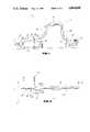
- FIG. 1is a schematic top plan view of the leak detection system of this invention shown in use with a continuous product processing operation;
- FIG. 2is a schematic lateral plan view of the leak detection system shown in FIG. 1;
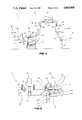
- FIG. 3is a schematic lateral plan view of the preferred embodiment of the leak detection system of this invention.
- FIG. 4is a close-up schematic lateral plan view of the embodiment of FIG. 3, showing the high level and low level container content detectors and the high and low level container rejectors;
- FIG. 5is a schematic top plan view of the leak detection system embodiment shown in FIG. 3;
- FIG. 6is a close-up schematic top plan view of the embodiment of FIG. 5 showing the low level container rejector and reject container chute;
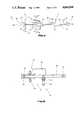
- FIG. 7is a frontal view of a container disposed in the continuous squeezing means of the leak detection system
- FIG. 8is a frontal view of the mainframe and drive system of the leak detection system.
- FIG. 9is a perspective view of the continuos flexible belts used in the squeezing means of this invention.
- FIGS. 1 and 2illustrate the leak detection system 10 which is designed to be incorporated in a continuous product processing operation.
- the leak detection system 10has a compressive transfer mechanism 12 and a take-away conveyor 14.
- the filled and sealed pliable containers 50enter the leak detection system 10 on an infeed conveyor 70 or other suitable conveyance means which is part of the processing operation and which transfers the individual containers 50 to the compressive transfer mechanism 12.
- the pliable containersare typically filled with liquid or fluid contents and which may or may not have a gas filled headspace.
- the containers 50are typically composed of plastic or a similarly pliable materials.
- the containersare transported by the compressive transfer mechanism 12 and subsequently placed onto the take-away or line conveyor 14.
- the line conveyor 14has a pair of high and low fill level detectors 35 and 36 placed adjacent thereto at predetermined locations.
- the detectors 35 and 36measure fill level displacements in the pliable containers or bottles 50 to detect any possible leaks.
- Working in conjunction with the detectors 35 and 36are a pair of rejectors 33 and 34, respectively, which are timed to push the rejected bottles out of the product flow stream.
- the high fill level detector 35is placed adjacent the compressive transfer mechanism 12, and preferably, within a range of its end.
- the low fill level detector 36is located downstream and adjacent the line conveyor 14.
- the high liquid level detector 35 and the low liquid level detector 36are of the gamma-ray type detection systems, as known in the art. Alternatively, they may be photo-eyes, proximity switches or some other suitable fill level detectors.
- the high and low level detectorsmeasure the product levels in the containers which have a desirable predetermined level range set by the manufacturer.
- the compressive transfer mechanism 12places a constant predetermined pressure on the exterior of the pliable containers.
- Containers with relatively small leakshave been found to discharge small amounts of air or liquid contents when squeezed by the compressive transfer mechanism 12. If air or a small quantity of contents are discharged, containers having a headspace will have a higher fill level while being subjected to the external pressure or immediately after the release of the external pressure. And, these high level containers will be detected and rejected by the high level mechanisms. The high level reject mechanisms are therefore desirable for use with containers having a headspace to detect small leaks.
- Containers with relatively large leakshave been found to discharge larger amounts of contents only or contents and air. If contents are discharged due to a large leak, the containers will have lower fill levels upon release of the external pressure and recovery to their approximate uncompressed shape due to air intake through the leak area. Any low level containers or bottles will be detected and rejected by the low level mechanisms.
- the compressive transfer mechanism 12is adjustable to permit variation of the compressive pressure so as to be operative on a variety of pliable container structures, compositions, and sizes having varying fluid or product contents. Additionally, the container may be completely filled or may have a headspace filled with air or purged with a gas.
- the construction of the compressive transfer mechanism 12is preferably a double-sided conveyor having endless belts of a molded rubber material or similar pliable structure, such as polyurethane.
- the beltspreferably have a number of cleat members spaced to engage the opposite sides of the bottles to grip and assist in squeezing the containers during the transfer operation.
- the compressive transfer mechanism 12has a support frame 24 preferably with vertical and horizontal sections 66 and 67 which provide an elevated configuration to permit the bottles to be subjected to external pressure for a specified period of time while maximizing line speed and travel distance without increasing required floor space.
- a support frame 24preferably with vertical and horizontal sections 66 and 67 which provide an elevated configuration to permit the bottles to be subjected to external pressure for a specified period of time while maximizing line speed and travel distance without increasing required floor space.
- Such an overhead configurationalso allows operator personnel to move about and inspect the detection system by enabling them to walk underneath it without crossovers or similar structures.
- the configurationmay be straight line and level.
- the support frame 24is supported at its inlet end by a support structure or legs 23, and at its outlet end by a frame 20.
- the system 10has a drive mechanism 15 for powering the compressive transfer mechanism 12, and a synchronized drive mechanism 29 for powering the line conveyor 14.
- the operation of the conveyors 12 and 14, the detectors 35 and 36, and the rejectors 33 and 34are synchronized for the particular type, size, speed and spacing of the containers.
- a reject container hopper 61is disposed adjacent the line conveyor 14 and opposite the rejectors 33 and 34.
- FIGS. 3 and 5show the preferred embodiment 71 of the leak detector system from a side and top view respectively.
- the system 71has a main frame and drive mechanism 11, a compressive transfer conveyor 12, and infeed section 13 and an outfeed section 14.
- the infeed section 13is communicatively connected to a continuous input of filled and sealed pliable containers.
- the compressive transfer conveyor 12is synchronized to receive containers at the inlet section 13 from an infeed conveyor (not shown) or the like.
- the compressive transfer conveyor 12then grasps and applies a predetermined pressure on the containers while moving them towards the outlet section 14.
- the conveyor 12is preferably run at a slightly faster speed than that of the infeed conveyor to more uniformly space or group the containers 50.
- the compressive transfer conveyor 12is preferably a Flex-Link, side transfer, materials handling conveyor manufactured by SKF Norden, Goteborg, Sweden.
- the conveyor 12has a support frame 24 and a pair of conveyor beams 22.
- the elevating frame 24provides adjustable support for the conveyor beams 22.
- the support frame 24is supported at the inlet section end 13 by a support leg 23 and at the outfeed section 14 by the mainframe and drive mechanism 11.
- the support frame 24is in an overhead configuration having both horizontal and vertical sections 67 and 66 to provide improved access by personnel and to maximize container transfer distance and, therefore, compression time, while minimizing production space.
- nozzle holders 32 having nozzles 31are disposed about the side transfer conveyor 12.
- the nozzles 30spray a fine mist of water or a suitable solvent on the transported containers for sanitation purposes.
- Leaky containersmay expel or drip product contents onto the side transfer conveyor 12 and adjoining containers while being compressed.
- the mist from nozzles 30keeps both the conveyor 12 and the containers 50 free from any such discharged product contents.
- the adjustable compressive conveyor 12further has a pair of revolving endless flexible conveyor chains or belts 72 and 73.
- the flexible chains 72 and 73are connected to and ride on slide rails or wearstrips 52 which are attached to the conveyor beams 22.
- the conveyor beams 22are rectilinear, elongated and curved at each end. Rotatable sprockets 21 and 55 having vertical axis are disposed at each curved end.
- the conveyor beams 22each have a top 80 and bottom 81 portion which are separated by a spacer block 51. The separation of the top 80 and bottom 81 portions creates a channel in the sides of the beams 22 in which the belts 72 and 73 travel.
- the beams 22are arranged in a side by side configuration.
- the spacing between the beams 22is adjustable and dependent upon the diameter and container composition, as well as the nature and amount of product contents.
- the flexible chains 72 and 73contact the sprockets 21 and 55 at the beam 22 ends and rotate around each beam 22 so that the opposing portions of each belt 72 and 73 travel in the same direction.
- a container 50 located between the beams 22is squeezingly transported by the rotating belts 72 and 73.
- the flexible conveyor chains or belts 72 and 73consists of plastic universal links 63 joined together by plastic pivots 65 and stainless steel pins 69.
- Each link 63consists of a generally flat and rectangular body portion 30 having opposing teeth portions 79 extending from its two long ends which mesh with adjacent links.
- a generally square knuckle 48is attached to the inwardly disposed side of each body portion 31 by the rotatable pivot 65.
- a pair of tangs 53are offset slightly and extend vertically from two sides of the knuckle 48.
- the pins 69extend axially through the tangs 53 and join the pivot 65 of the adjacent link in a perpendicular and moveable fashion to form two axis.
- the links 63 of each belt 72 or 73articulate about these two axis.
- the teeth of the sprockets 21 and 55engage the tangs 53 for rotating the belts 72 and 73.
- the conveyor chains 72 and 73further have cleats 47 which grasp and squeeze the containers 50 and aid in holding the containers, particularly for vertical movement.
- the cleats 47are disposed on the outwardly facing side of each body portion 30.
- the cleats 47are preferably of a configuration having several rows of flexible fingers.
- the cleats 47may also be of a solid and flexible configuration.
- FIGS. 7 and 8show a pliable, liquid filled container 50 disposed and held between the opposing flexible chains 72 and 73.
- the belts 72 and 73are adjustable via belt adjusters 64 mounted on the elevating frame 24 (shown in FIGS. 3 and 4) to accommodate various size containers and to vary the spacing between the belts to control the external pressure on the containers 50.
- Horizontal mounting brackets 58extend from two sides of the elevating frame 24.
- a vertical mounting bracket 45is connected to each horizontal mounting bracket 58.
- the connectionhas a vertical adjustment slot 59 and a horizontal adjustment slot 60 to provide lateral and vertical movement in response to the belt adjusters 64.
- a horizontal and slotted bracket adjuster 49is disposed at the connection of the vertical mounting bracket 45 to the bottom portion 81 of the beams 22 for adjustment in a second horizontal plane.
- the support frame 24additionally serves to support containers which may slip from the grasp of the belts 72 and 73, for example, when a container 50 has a large leak.
- a container guide 62is disposed on the mainframe and drive section 11 at the termination point of the support frame 24 to also deal with any dropped defective containers.
- the mainframe and drive mechanism 11is connected with a supplies driving power to the compressive transfer conveyor 12.
- the mainframe and drive mechanism 11also supports one end of the line conveyor 68.
- the line conveyor 68is driven by a separate, downstream power source (not shown) which is synchronized with the speed of the compressive transfer conveyor 12.
- the mainframe and drive section 11consists of a frame 20, a motor 15, and connection elements to convert power from the motor 15 to the compressive transfer conveyor 12.
- the motor 15is connected to a reducer and torque limiter assembly 16 which is connected via a drive chain 54 and sprocket 38 to a pair of gear assemblies 18.
- Each gear assembly 18has a drive shaft 19, a pair of U-joints 25, and a head shaft 26.
- the U-joints 25permit movement of the drive shafts 19 when the beams 22 are adjustably spaced.
- the drive shafts 19each have a drive sprocket 21 connected to its head shaft 26.
- the rotatable drive sprockets 21are connected to the conveyor beam 22 ends and engage the tangs 53 of the flexible conveyor chains 72 and 73 for rotation and movement.
- the outfeed section 14 of the system 71is extended from and aligned with the compressive transfer conveyor 12 and the mainframe and drive mechanism 11.
- the outfeed section 14has a high level container content detection system 35, a high level container rejector 33, a low level container content detection system 36, a low level container rejector 34, and the outlet line conveyor 68.
- the line conveyor 68has a flexible chain which rotates around a substantially horizontal axis.
- the line conveyor 68 chainis connected to a chain rail 28 which is supported by a conveyor side plate 27.
- the line conveyor 68engages a tail sprocket 39 which is mounted on an idler shaft 40.
- the line conveyor 68is driven by a separate, downstream drive mechanism (not shown).
- the outfeed section 14 elementsare synchronized and cooperate to receive, transport and analyze containers emerging from the compressive transfer conveyor 12.
- the container streamis transported onto the level and uniform top surface of the line conveyor 68, which provides a suitable environment for testing container content levels.
- the high level container content detector 35is comprised of a source of transmitter 75, a receiver 74 and a cross connector 76.
- the source 75is disposed on one side of the compressive transfer conveyor 12 and is located above the position of the belts 72 and 73.
- the source 75has a beam outlet 77.
- the receiver 74is located on a support structure 37 on the opposite side of the compressive transfer conveyor 12 and in alignment with the source 75.
- the receiver 74has a beam inlet portion 78. Both the source 75 and the receiver 74 are mounted on the mainframe and drive mechanism 11.
- the low level container content detector 36is comprised of the same elements as the high level container content detector 35.
- Its source and receiverare disposed on opposite sides of the line conveyor 68 so that the beam is transmitted across the path of travel of the containers 50.
- container content detectorsis the GAMMA 101P Fill Level Monitor manufactured by Peco Controls Corp. of Milpitaz, California.
- This leak detector embodimentoffers high sensitivity and high reliability particularly for use with opaque and/or pigmented plastic containers.
- other fill level detectors known in the artsuch as high intensity photo-eyes, infrared detectors, capacitive proximity switches, ultrasound detectors and microwave detectors, are usable with the leak detection system 71 depending upon the type of container to be tested as well as the nature of the product contents.
- the high level container content detector 35 and low level container content detector 36provide means for monitoring the fill level of the pliable containers as they are subjected to and released from the external pressure provided by the transfer conveyor 12.
- the high level container content detector 35is disposed on the sides of the compressive transfer conveyor 12 at a predetermined location proximate its outlet end. The detector 35 is located at a position where the containers 50 are still under pressure or at a position immediately following the release of the external pressure. Thus, the high level container content detector 35 is positioned at a location where the containers 50 are under pressure or immediately after the release of the external pressure and have been subjected to such external pressure by the compressive transfer conveyor 12 for a predetermined length of time.
- the high level container content detector 35detects elevated product content levels caused by the discharge of air and/or liquid contents through relatively small leaks while the container is under external pressure.
- the high level detector 35directs a beam through a bottle neck, for example, at a predetermined height above the normal content level of a filled and sealed container under pressure. An elevated liquid level disrupts the beam to detect a leak in the container.
- the low level container content detector 36is located adjacent the line conveyor 68 at a position downstream from the compressive transfer mechanism 12 outlet end. The detector 36 is operative at a predetermined point after the container 50 has been released from the external pressure. The distance between the detector 36 and the outlet of the compressive transfer conveyor 12 is dependent upon line speed and time required for the compressed containers to recover their uncompressed shape.
- the low level container content detector 36detects depressed content levels caused by the discharge of contents and subsequent intake of air through relatively larger leaks.
- the detector 36directs a beam through the bottle at a level which is a predetermined distance below the normal content levels of a filled container. The lack of liquid in the normal range due to a low level thus fails to disrupt the beam to detect a relatively larger leak in the container.
- the high and low level rejectors 33 and 34are synchronized with the respective fill level detectors 35 and 36.
- the rejectors 33 and 34comprise solenoid and air cylinder assemblies 46 which are mounted to the conveyor side plate 27 via mount structures 57 so that the rejectors operate perpendicularly to the direction of travel of the line conveyor 68.
- the air cylinders 46have pistons 56 with a pusher face to contact the containers while they are being transported on the line conveyor 68. Actuation of either rejector 33 or 34 moves the piston outward to eject the detected leaky container from the line conveyor 68.
- other actuation means known in the art, such as air blast rejectorsare usable with the leak detection system 71.
- the rejectors 33 and 34are synchronized by an internal logic and control system of the gamma-ray detectors 35 and 36.
- Other conventional timing or logic means known in the artmay be used to synchronize the rejectors 33 and 34 with the fill level detectors.
- the outfeed section 14further has reject container chutes and hoppers.
- One reject container chute 41is shown aligned with the high level rejector 33 and disposed on the opposite side of the line conveyor 68 to receive defective containers.
- a reject container chute 42is similarly aligned with the low level rejector 34.
- the reject container chutes 41 and 42are preferably downwardly angled plates which extend from the conveyor side plate 27.
- the chutes 41 and 42guide rejected containers to a reject container hopper or hoppers (not shown) for subsequent disposal or processing.
- Adjustable guide rails 43 and guide rail brackets 44are located adjacent the line conveyor 68 downstream of the rejectors 33 and 34.
- the guide rails 43serve to contain and guide the tested containers or bottles on the line conveyor 68.
- the leak detection system of this inventionprovides a process or method for detecting leaks in each of a plurality of moving, sealed, pliable, and filled containers.
- the systemapplies a continuous and predetermined squeezing force on each moving container for a predetermined period of time.
- the systemdetects for an increase in the fill level with respect to a predetermined norm of each moving container and then detects for a decrease in the fill level with respect to a predetermined norm of each moving container thereafter. Should any container leaks be detected, timed and cooperating ejectors are used to remove the defective containers from the moving container stream.
Landscapes
- Physics & Mathematics (AREA)
- General Physics & Mathematics (AREA)
- Examining Or Testing Airtightness (AREA)
Abstract
Description
Claims (19)
Priority Applications (1)
| Application Number | Priority Date | Filing Date | Title |
|---|---|---|---|
| US07/162,185US4864848A (en) | 1988-02-29 | 1988-02-29 | Leak detection system |
Applications Claiming Priority (1)
| Application Number | Priority Date | Filing Date | Title |
|---|---|---|---|
| US07/162,185US4864848A (en) | 1988-02-29 | 1988-02-29 | Leak detection system |
Publications (1)
| Publication Number | Publication Date |
|---|---|
| US4864848Atrue US4864848A (en) | 1989-09-12 |
Family
ID=22584531
Family Applications (1)
| Application Number | Title | Priority Date | Filing Date |
|---|---|---|---|
| US07/162,185Expired - LifetimeUS4864848A (en) | 1988-02-29 | 1988-02-29 | Leak detection system |
Country Status (1)
| Country | Link |
|---|---|
| US (1) | US4864848A (en) |
Cited By (20)
| Publication number | Priority date | Publication date | Assignee | Title |
|---|---|---|---|---|
| US5333492A (en)* | 1990-03-20 | 1994-08-02 | Product Suppliers Ag | Process and apparatus for leak-testing a package |
| US5767392A (en)* | 1996-08-28 | 1998-06-16 | The Clorox Company | Method and apparatus for leak testing containers having a flexible side wall structure |
| US5918270A (en)* | 1995-07-07 | 1999-06-29 | Heuft Systemtechnik Gmbh | Process and device for testing deformable containers for tightness |
| US5929337A (en)* | 1994-11-11 | 1999-07-27 | M & A Packaging Services Limited | Non-mechanical contact ultrasound system for monitoring contents of a moving container |
| US6234023B1 (en)* | 1995-11-09 | 2001-05-22 | M & A Packaging Services Limited | Ultrasonic monitoring technique for containers and apparatus to carry it out |
| US6358471B1 (en)* | 1998-07-31 | 2002-03-19 | Tosoh Corporation | Automatic measuring apparatus |
| US6427524B1 (en)* | 1999-10-19 | 2002-08-06 | Benthos, Inc. | Multiple sensor in-line container inspection apparatus and method |
| US6711939B2 (en)* | 2001-12-07 | 2004-03-30 | Lockheed Martin Corporation | Method and system for expelling test-sample volumes from luggage/packages |
| US20040129081A1 (en)* | 2003-01-08 | 2004-07-08 | Packaging Technologies & Inspection Llc | Method and apparatus for airborne ultrasonic testing of package and container seals |
| US20050039544A1 (en)* | 2003-08-22 | 2005-02-24 | Jones Richard T. | Flow meter using an expanded tube section and sensitive differential pressure measurement |
| WO2004072587A3 (en)* | 2003-02-05 | 2005-09-29 | Benthos Inc | Indirect contact container measurement |
| US20050268700A1 (en)* | 2004-06-04 | 2005-12-08 | Edward James Strand | Container leak detection apparatus and method |
| US20060042357A1 (en)* | 2004-08-26 | 2006-03-02 | Holzer Francis J | Carrier line oriented spin high voltage leak detection system and method |
| JP2007276854A (en)* | 2006-04-10 | 2007-10-25 | Kao Corp | Dirt detection apparatus |
| US20080264182A1 (en)* | 2003-08-22 | 2008-10-30 | Jones Richard T | Flow meter using sensitive differential pressure measurement |
| US20090211206A1 (en)* | 2006-07-20 | 2009-08-27 | Crown Packaging Technology, Inc. | Method for testing can ends |
| US20130118233A1 (en)* | 2009-12-29 | 2013-05-16 | Nestec S.A. | Seal integrity evaluation device and method of use thereof |
| US9200993B2 (en) | 2011-11-01 | 2015-12-01 | Teledyne Instruments, Inc. | Flexible container inspection |
| CN113275268A (en)* | 2021-06-25 | 2021-08-20 | 济南茂通检测设备有限公司 | Air leakage detection device and detection method for bagged product |
| US20230173547A1 (en)* | 2020-08-18 | 2023-06-08 | G.D S.P.A. | Support for transporting containers in a microwave inspection device and a device and method of inspection of containers using the support |
Citations (17)
| Publication number | Priority date | Publication date | Assignee | Title |
|---|---|---|---|---|
| US2999591A (en)* | 1958-10-23 | 1961-09-12 | Industrial Nucleonics Corp | Container inspection system |
| US3038606A (en)* | 1957-04-18 | 1962-06-12 | Electronic Associates Ltd | Automatic level inspector |
| US3094213A (en)* | 1960-06-30 | 1963-06-18 | Industrial Automation Corp | Fill-height inspection device for fluid in bottles |
| US3133638A (en)* | 1960-06-20 | 1964-05-19 | Industrial Dynamics Co | Inspection apparatus |
| US3225191A (en)* | 1962-06-01 | 1965-12-21 | Industrial Dynamics Co | Infrared liquid level inspection system |
| US3232429A (en)* | 1963-05-31 | 1966-02-01 | Industrial Nucleonics Corp | Fill level detector |
| US3509996A (en)* | 1967-11-24 | 1970-05-05 | Continental Can Co | Defective package detector |
| US3683677A (en)* | 1970-06-22 | 1972-08-15 | David S Harris | Leak detector |
| US3805593A (en)* | 1968-10-23 | 1974-04-23 | Owens Illinois Inc | Leak detector |
| US3835698A (en)* | 1972-07-17 | 1974-09-17 | A Zappia | Tester head |
| US4019370A (en)* | 1975-10-24 | 1977-04-26 | Farm Stores, Inc. | Leak testing device and method for plastic bottles |
| US4024956A (en)* | 1975-11-20 | 1977-05-24 | American Brands, Inc. | Method and apparatus for detecting leaks |
| US4055252A (en)* | 1976-03-25 | 1977-10-25 | Barry-Wehmiller Company | Container liquid level detector apparatus |
| US4390782A (en)* | 1980-11-17 | 1983-06-28 | Justus Technik Gmbh Industrie-Anlagen | Method and apparatus for measuring the liquid level of containers |
| EP0230367A2 (en)* | 1986-01-13 | 1987-07-29 | Daiwa Can Company, Limited | Apparatus for judging inner pressure of filled can |
| US4697452A (en)* | 1985-05-09 | 1987-10-06 | Bouwe Prakken | Apparatus for testing the leaktightness of filled, closed packages of flexible material |
| US4756184A (en)* | 1987-03-12 | 1988-07-12 | General Mills, Inc. | Apparatus and method for seal testing flexible containers |
- 1988
- 1988-02-29USUS07/162,185patent/US4864848A/ennot_activeExpired - Lifetime
Patent Citations (17)
| Publication number | Priority date | Publication date | Assignee | Title |
|---|---|---|---|---|
| US3038606A (en)* | 1957-04-18 | 1962-06-12 | Electronic Associates Ltd | Automatic level inspector |
| US2999591A (en)* | 1958-10-23 | 1961-09-12 | Industrial Nucleonics Corp | Container inspection system |
| US3133638A (en)* | 1960-06-20 | 1964-05-19 | Industrial Dynamics Co | Inspection apparatus |
| US3094213A (en)* | 1960-06-30 | 1963-06-18 | Industrial Automation Corp | Fill-height inspection device for fluid in bottles |
| US3225191A (en)* | 1962-06-01 | 1965-12-21 | Industrial Dynamics Co | Infrared liquid level inspection system |
| US3232429A (en)* | 1963-05-31 | 1966-02-01 | Industrial Nucleonics Corp | Fill level detector |
| US3509996A (en)* | 1967-11-24 | 1970-05-05 | Continental Can Co | Defective package detector |
| US3805593A (en)* | 1968-10-23 | 1974-04-23 | Owens Illinois Inc | Leak detector |
| US3683677A (en)* | 1970-06-22 | 1972-08-15 | David S Harris | Leak detector |
| US3835698A (en)* | 1972-07-17 | 1974-09-17 | A Zappia | Tester head |
| US4019370A (en)* | 1975-10-24 | 1977-04-26 | Farm Stores, Inc. | Leak testing device and method for plastic bottles |
| US4024956A (en)* | 1975-11-20 | 1977-05-24 | American Brands, Inc. | Method and apparatus for detecting leaks |
| US4055252A (en)* | 1976-03-25 | 1977-10-25 | Barry-Wehmiller Company | Container liquid level detector apparatus |
| US4390782A (en)* | 1980-11-17 | 1983-06-28 | Justus Technik Gmbh Industrie-Anlagen | Method and apparatus for measuring the liquid level of containers |
| US4697452A (en)* | 1985-05-09 | 1987-10-06 | Bouwe Prakken | Apparatus for testing the leaktightness of filled, closed packages of flexible material |
| EP0230367A2 (en)* | 1986-01-13 | 1987-07-29 | Daiwa Can Company, Limited | Apparatus for judging inner pressure of filled can |
| US4756184A (en)* | 1987-03-12 | 1988-07-12 | General Mills, Inc. | Apparatus and method for seal testing flexible containers |
Non-Patent Citations (2)
| Title |
|---|
| SKF Norden, Flex Link Brochure 3527U, 1985.* |
| SKF Norden, Flex-Link Brochure 3527U, 1985. |
Cited By (35)
| Publication number | Priority date | Publication date | Assignee | Title |
|---|---|---|---|---|
| US5333492A (en)* | 1990-03-20 | 1994-08-02 | Product Suppliers Ag | Process and apparatus for leak-testing a package |
| US5929337A (en)* | 1994-11-11 | 1999-07-27 | M & A Packaging Services Limited | Non-mechanical contact ultrasound system for monitoring contents of a moving container |
| US5918270A (en)* | 1995-07-07 | 1999-06-29 | Heuft Systemtechnik Gmbh | Process and device for testing deformable containers for tightness |
| US6234023B1 (en)* | 1995-11-09 | 2001-05-22 | M & A Packaging Services Limited | Ultrasonic monitoring technique for containers and apparatus to carry it out |
| US5767392A (en)* | 1996-08-28 | 1998-06-16 | The Clorox Company | Method and apparatus for leak testing containers having a flexible side wall structure |
| US6358471B1 (en)* | 1998-07-31 | 2002-03-19 | Tosoh Corporation | Automatic measuring apparatus |
| US6427524B1 (en)* | 1999-10-19 | 2002-08-06 | Benthos, Inc. | Multiple sensor in-line container inspection apparatus and method |
| EP1222449A4 (en)* | 1999-10-19 | 2006-07-05 | Benthos Inc | Multiple sensor in-line container inspection |
| US6711939B2 (en)* | 2001-12-07 | 2004-03-30 | Lockheed Martin Corporation | Method and system for expelling test-sample volumes from luggage/packages |
| US20040129081A1 (en)* | 2003-01-08 | 2004-07-08 | Packaging Technologies & Inspection Llc | Method and apparatus for airborne ultrasonic testing of package and container seals |
| US6840108B2 (en) | 2003-01-08 | 2005-01-11 | Packaging Technologies & Inspection Llc | Method and apparatus for airborne ultrasonic testing of package and container seals |
| US20050115324A1 (en)* | 2003-01-08 | 2005-06-02 | Anton Stauffer | Systems and apparatus for airborne ultrasonic testing of package and container seals |
| US6920793B2 (en) | 2003-01-08 | 2005-07-26 | Packaging Technologies & Inspection Llc | Systems and apparatus for airborne ultrasonic testing of package and container seals |
| WO2004072587A3 (en)* | 2003-02-05 | 2005-09-29 | Benthos Inc | Indirect contact container measurement |
| US20080178686A1 (en)* | 2003-08-22 | 2008-07-31 | Jones Richard T | Flow meter using an expanded tube section and sensitive differential pressure measurement |
| US20070272033A9 (en)* | 2003-08-22 | 2007-11-29 | Jones Richard T | Flow meter using an expanded tube section and sensitive differential pressure measurement |
| US7658117B2 (en) | 2003-08-22 | 2010-02-09 | Weatherford/Lamb, Inc. | Flow meter using an expanded tube section and sensitive differential pressure measurement |
| US20080264182A1 (en)* | 2003-08-22 | 2008-10-30 | Jones Richard T | Flow meter using sensitive differential pressure measurement |
| US6910388B2 (en) | 2003-08-22 | 2005-06-28 | Weatherford/Lamb, Inc. | Flow meter using an expanded tube section and sensitive differential pressure measurement |
| US20070062307A1 (en)* | 2003-08-22 | 2007-03-22 | Jones Richard T | Flow meter using an expanded tube section and sensitive differential pressure measurement |
| US20050039544A1 (en)* | 2003-08-22 | 2005-02-24 | Jones Richard T. | Flow meter using an expanded tube section and sensitive differential pressure measurement |
| US7320252B2 (en) | 2003-08-22 | 2008-01-22 | Weatherford/Lamb, Inc. | Flow meter using an expanded tube section and sensitive differential pressure measurement |
| US7266993B2 (en) | 2004-06-04 | 2007-09-11 | Air Logic Power Systems, Inc. | Container leak detection apparatus and method |
| US20050268700A1 (en)* | 2004-06-04 | 2005-12-08 | Edward James Strand | Container leak detection apparatus and method |
| US7038464B2 (en)* | 2004-08-26 | 2006-05-02 | Diamond Machine Werks, Inc. | Carrier line oriented spin high voltage leak detection system and method |
| US20060042357A1 (en)* | 2004-08-26 | 2006-03-02 | Holzer Francis J | Carrier line oriented spin high voltage leak detection system and method |
| JP2007276854A (en)* | 2006-04-10 | 2007-10-25 | Kao Corp | Dirt detection apparatus |
| US20090211206A1 (en)* | 2006-07-20 | 2009-08-27 | Crown Packaging Technology, Inc. | Method for testing can ends |
| US7673491B2 (en)* | 2006-07-20 | 2010-03-09 | Crown Packaging Technology, Inc. | Method for testing can ends |
| US20130118233A1 (en)* | 2009-12-29 | 2013-05-16 | Nestec S.A. | Seal integrity evaluation device and method of use thereof |
| US8973425B2 (en)* | 2009-12-29 | 2015-03-10 | Nestec S.A. | Seal integrity evaluation device and method of use thereof |
| US9200993B2 (en) | 2011-11-01 | 2015-12-01 | Teledyne Instruments, Inc. | Flexible container inspection |
| US20230173547A1 (en)* | 2020-08-18 | 2023-06-08 | G.D S.P.A. | Support for transporting containers in a microwave inspection device and a device and method of inspection of containers using the support |
| US12226804B2 (en)* | 2020-08-18 | 2025-02-18 | G.D S.P.A. | Support for transporting containers in a microwave inspection device and a device and method of inspection of containers using the support |
| CN113275268A (en)* | 2021-06-25 | 2021-08-20 | 济南茂通检测设备有限公司 | Air leakage detection device and detection method for bagged product |
Similar Documents
| Publication | Publication Date | Title |
|---|---|---|
| US4864848A (en) | Leak detection system | |
| US4024956A (en) | Method and apparatus for detecting leaks | |
| US4517827A (en) | Apparatus and method for testing for leakages in hermetically-sealed packages | |
| US5505312A (en) | Inspection machine for bottles or the like | |
| US5057055A (en) | Sausage link handling and packaging machine | |
| US3924732A (en) | Apparatus for unscrambling and orienting overcaps | |
| US4862732A (en) | Leak testing | |
| US5802803A (en) | Case packer | |
| US8578760B2 (en) | Container inspection utilizing linear force actuator | |
| JPH0513681Y2 (en) | ||
| US20210354933A1 (en) | Method and assembly for transferring products | |
| JP2529721Y2 (en) | Packaging machine | |
| US4457420A (en) | Apparatus for diverting objects from a main conveyor path | |
| US5072797A (en) | Checkweighing method and apparatus | |
| US4044891A (en) | Can testing conveyor | |
| JP3408755B2 (en) | Bottle sorting device | |
| US6164436A (en) | Conveyor | |
| EP0540148A1 (en) | Bag seal tester | |
| JP3614326B2 (en) | Inspection equipment for hollow molded products | |
| JP6348294B2 (en) | Tube container inspection equipment | |
| EP0456155B1 (en) | Sausage link handling and packaging machine | |
| US5533315A (en) | Closure checking apparatus for bagged goods | |
| US5570567A (en) | Packing of cylindrical articles | |
| US3877199A (en) | Frankfurter packaging machine | |
| EP0137662A1 (en) | Method and apparatus for checking packages |
Legal Events
| Date | Code | Title | Description |
|---|---|---|---|
| AS | Assignment | Owner name:MINNESOTA AUTOMATION, INC., FIRST STREET SOUTHWEST Free format text:ASSIGNMENT OF ASSIGNORS INTEREST.;ASSIGNOR:IRVINE, GERALD O.;REEL/FRAME:004942/0298 Effective date:19880825 Owner name:MINNESOTA AUTOMATION, INC., A CORP. OF MINNESOTA,M Free format text:ASSIGNMENT OF ASSIGNORS INTEREST;ASSIGNOR:IRVINE, GERALD O.;REEL/FRAME:004942/0298 Effective date:19880825 | |
| STCF | Information on status: patent grant | Free format text:PATENTED CASE | |
| FEPP | Fee payment procedure | Free format text:PAT HLDR NO LONGER CLAIMS SMALL ENT STAT AS SMALL BUSINESS (ORIGINAL EVENT CODE: LSM2); ENTITY STATUS OF PATENT OWNER: LARGE ENTITY Free format text:PAYOR NUMBER ASSIGNED (ORIGINAL EVENT CODE: ASPN); ENTITY STATUS OF PATENT OWNER: LARGE ENTITY | |
| REMI | Maintenance fee reminder mailed | ||
| FPAY | Fee payment | Year of fee payment:4 | |
| SULP | Surcharge for late payment | ||
| AS | Assignment | Owner name:CHEMICAL BANK, AS ADMINISTRATIVE AGENT, NEW YORK Free format text:SECURITY INTEREST;ASSIGNOR:RIVERWOOD INTERNATIONAL USA, INC.;REEL/FRAME:007961/0164 Effective date:19960328 Owner name:RIVERWOOD INTERNATIONAL USA, INC., GEORGIA Free format text:ASSIGNMENT OF ASSIGNORS INTEREST;ASSIGNOR:RIVERWOOD INTERNATIONAL CORPORATION;REEL/FRAME:007927/0768 Effective date:19960328 | |
| FPAY | Fee payment | Year of fee payment:8 | |
| FPAY | Fee payment | Year of fee payment:12 | |
| AS | Assignment | Owner name:THE CHASE MANHATTAN BANK, AS ADMINISTRATIVE AGENT, Free format text:SECURITY INTEREST;ASSIGNOR:RIVERWOOD INTERNATIONAL CORPORATION (DE CORPORATION);REEL/FRAME:012243/0374 Effective date:20010827 | |
| AS | Assignment | Owner name:RIVERWOOD INTERNATIONAL CORPORATION, GEORGIA Free format text:TERMINATION AND RELEASE OF SECURITY INTEREST IN PATENTS;ASSIGNOR:JPMORGAN CHASE BANK, AS ADMINISTRATIVE AGENT;REEL/FRAME:014363/0613 Effective date:20030808 | |
| AS | Assignment | Owner name:GRAPHIC PACKAGING INTERNATIONAL, INC., GEORGIA Free format text:MERGER AND CHANGE OF NAME;ASSIGNORS:GRAPHIC PACKAGING INTERNATIONAL, INC.;RIVERWOOD INTERNATIONAL CORPORATION;REEL/FRAME:014409/0295 Effective date:20030808 | |
| AS | Assignment | Owner name:JPMORGAN CHASE BANK, AS ADMINISTRATIVE AGENT, TEXAS Free format text:SECURITY INTEREST;ASSIGNOR:GRAPHIC PACKAGING INTERNATIONAL, INC.;REEL/FRAME:014074/0162 Effective date:20030808 Owner name:JPMORGAN CHASE BANK, AS ADMINISTRATIVE AGENT, TEXAS Free format text:INVALID RECORDING. PLEASE SEE RECORDING AT REEL 014074, FRAME 0162;ASSIGNOR:GRAPHIC PACKAGING INTERNATIONAL, INC. (DE CORPORATION);REEL/FRAME:014066/0194 Effective date:20030808 Owner name:JPMORGAN CHASE BANK, AS ADMINISTRATIVE AGENT, TEXA Free format text:INVALID RECORDING. PLEASE;ASSIGNOR:GRAPHIC PACKAGING INTERNATIONAL, INC. (DE CORPORATION);REEL/FRAME:014066/0194 Effective date:20030808 Owner name:JPMORGAN CHASE BANK, AS ADMINISTRATIVE AGENT, TEXA Free format text:SECURITY INTEREST;ASSIGNOR:GRAPHIC PACKAGING INTERNATIONAL, INC.;REEL/FRAME:014074/0162 Effective date:20030808 Owner name:JPMORGAN CHASE BANK, AS ADMINISTRATIVE AGENT, TEXA Free format text:INVALID RECORDING. PLEASE SEE RECORDING AT REEL 014074, FRAME 0162;ASSIGNOR:GRAPHIC PACKAGING INTERNATIONAL, INC. (DE CORPORATION);REEL/FRAME:014066/0194 Effective date:20030808 | |
| AS | Assignment | Owner name:BANK OF AMERICA, N.A., AS ADMINISTRATIVE AGENT,ILL Free format text:SECURITY INTEREST;ASSIGNOR:GRAPHIC PACKAGING INTERNATIONAL, INC.;REEL/FRAME:019458/0437 Effective date:20070516 Owner name:BANK OF AMERICA, N.A., AS ADMINISTRATIVE AGENT, IL Free format text:SECURITY INTEREST;ASSIGNOR:GRAPHIC PACKAGING INTERNATIONAL, INC.;REEL/FRAME:019458/0437 Effective date:20070516 Owner name:GRAPHIC PACKAGING INTERNATIONAL, INC., GEORGIA Free format text:TERMINATION OF SECURITY INTEREST;ASSIGNOR:JPMORGAN CHASE BANK, N.A., A NATIONAL BANKING ASSOCIATION;REEL/FRAME:019341/0940 Effective date:20070516 | |
| AS | Assignment | Owner name:GRAPHIC PACKAGING INTERNATIONAL, LLC, GEORGIA Free format text:CERTIFICATE OF CONVERSION;ASSIGNOR:GRAPHIC PACKAGING INTERNATIONAL, INC.;REEL/FRAME:045182/0983 Effective date:20171215 |