US4860936A - Method and structure for attaching adjustable backpack straps - Google Patents
Method and structure for attaching adjustable backpack strapsDownload PDFInfo
- Publication number
- US4860936A US4860936AUS07/011,250US1125087AUS4860936AUS 4860936 AUS4860936 AUS 4860936AUS 1125087 AUS1125087 AUS 1125087AUS 4860936 AUS4860936 AUS 4860936A
- Authority
- US
- United States
- Prior art keywords
- movable member
- track
- movable
- set forth
- base
- Prior art date
- Legal status (The legal status is an assumption and is not a legal conclusion. Google has not performed a legal analysis and makes no representation as to the accuracy of the status listed.)
- Expired - Lifetime
Links
- 238000000034methodMethods0.000titleclaimsdescription6
- 241000282472Canis lupus familiarisSpecies0.000claimsdescription11
- 239000000463materialSubstances0.000description7
- 238000009958sewingMethods0.000description4
- 238000013459approachMethods0.000description2
- 239000004033plasticSubstances0.000description2
- 229920003023plasticPolymers0.000description2
- 239000004753textileSubstances0.000description2
- 229920004943Delrin®Polymers0.000description1
- JOYRKODLDBILNP-UHFFFAOYSA-NEthyl urethaneChemical compoundCCOC(N)=OJOYRKODLDBILNP-UHFFFAOYSA-N0.000description1
- 230000003466anti-cipated effectEffects0.000description1
- 230000002457bidirectional effectEffects0.000description1
- 230000000295complement effectEffects0.000description1
- 230000006835compressionEffects0.000description1
- 238000007906compressionMethods0.000description1
- 230000001419dependent effectEffects0.000description1
- 230000000881depressing effectEffects0.000description1
- 238000006073displacement reactionMethods0.000description1
- 230000000694effectsEffects0.000description1
- 238000004519manufacturing processMethods0.000description1
- 239000002184metalSubstances0.000description1
- 238000012986modificationMethods0.000description1
- 230000004048modificationEffects0.000description1
- 239000004417polycarbonateSubstances0.000description1
- 229920000515polycarbonatePolymers0.000description1
- 229920000642polymerPolymers0.000description1
- 229920002635polyurethanePolymers0.000description1
- 239000004814polyurethaneSubstances0.000description1
Images


Classifications
- A—HUMAN NECESSITIES
- A45—HAND OR TRAVELLING ARTICLES
- A45F—TRAVELLING OR CAMP EQUIPMENT: SACKS OR PACKS CARRIED ON THE BODY
- A45F3/00—Travelling or camp articles; Sacks or packs carried on the body
- A45F3/04—Sacks or packs carried on the body by means of two straps passing over the two shoulders
- A45F3/047—Sacks or packs carried on the body by means of two straps passing over the two shoulders with adjustable fastenings for the shoulder straps or waist belts
Definitions
- This inventionrelates generally to the attachment and adjustment of straps to backpacks or rucksacks, and more particularly pertains to an assembly including a base member adapted to be secured to the backpack and including preferably a pair of parallel track members, a movable member adapted to ride the track members in a slidable attached but nonencircling manner through an adjacent unobstructed volume and to carry the backpack straps, and a locking structure to secure the movable member at selected positions along the track members.
- the attachment portionsinclude shoulder straps, a lower back pad, and often a waist belt.
- the strap portionshave been made adjustable by providing a plurality of redundant attachment points or a single attachment point with a plurality of guides to position the effective attachment of the shoulder strap to the backpack.
- Such redundant attachment pointsare cumbersome and expensive, and usually require a good deal of effort to change the particular adjustment.
- Such prior approacheshave generally involved substantial labor to provide individual positioning of and sewing of the multiple attachment points.
- Carried on the lightweight base memberis at least one, but preferably two rail or track members extending in a parallel relationship in the direction in which adjustment of the straps is desired.
- the base membermay be formed by attaching a length of webbing to the backpack inboard of the edges of the webbing such that the edges of the webbing form track members.
- a movable member including an arrangement, usually slots, adapted to receive the strapsis configured to engage and move along the track members in such a fashion as to provide a strong, partially encircling interface with easy and convenient relocation.
- encirclingdenotes enclosure but not necessarily enclosure equidistant from a point.
- An unobstructed volume adjacent the track membersis provided for free movement of the movable member even at points of attachment of the base member to the backpack.
- a releasable locking structureis provided between the base member and movable member to secure the movable member at any of a plurality of positions relative to the base member.
- the backpack strapsmay be conveniently positioned on the base member at selected points by sliding the movable member on the track members, and thus adjusted and secured by means of the releasable locking structure.
- the fasteners attaching the base member to the backpackare positioned to permit movement of the movable member through the unobstructed volume along the length of the track member free of interference by the fastening means.
- an object of the present inventionis to provide a new and improved method and structure for securing and positioning straps and similar items bearing against a wearer to a backpack.
- Another object of the present inventionis to provide a new and improved method of structure for providing for adjustment of straps attached to a backpack.
- Yet another object of the present inventionis to provide a new and improved method and structure for attaching an adjustable strap securing means to a backpack proper in a manner that permits movement free of interference by the attachment points of the structure to a backpack as a result of a nonencircling interface between the fixed and movable portions of the structure.
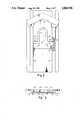
- FIG. 1is a perspective view of a typical backpack arrangement including a shoulder strap attachment means in accord with the instant invention
- FIG. 2is a front view of the shoulder strap adjustment means of FIG. 1 which is in part cut away;
- FIG. 3is a top view of the structure set forth in FIG. 2;
- FIG. 4is a front view of a structure similar to that of FIG. 2, but illustrating a different locking structure
- FIG. 5is a front view of yet another variation of an adjustable shoulder strap attachment means according to the instant invention.
- FIG. 6is a section view along section line VI--VI illustrating the engagement and locking structure of FIG. 5;
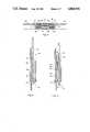
- FIG. 7is a perspective view similar to that of FIG. 1, but illustrating another embodiment of a shoulder strap attachment means in accord with the instant inventions;
- FIG. 8is an exploded view of the movable member shown in FIG. 7;
- FIG. 9is a lateral cross-section along section line IX--IX of the assembled base member and movable member shown in FIG. 7;
- FIG. 10is a longitudinal cross-section along section line XI--XI of the assembled base member and movable member shown in FIG. 7;
- FIG. 11is a cross-sectional view as shown in FIG. 9 with the movable member components in the "release" position;
- FIG. 12is a perspective view similar to that of FIG. 7 but illustrating a waist belt embodiment of the attachment means in accord with the instant invention.
- Adjustable shoulder strap attachment assembly 12includes a base member 14 typically attached by stitches 16 to backpack 10.
- a pair of parallel undercut rail members 18are defined on base member 14 and include a plurality of opposed openings 20 defined therein as will be discussed in more detail below.
- Movable member 24is configured to engage and slide within rail members 18 but to not fully encircle rail members 18, as is illustrated in more detail in FIGS. 2 and 3.
- a pair of openings 26are defined through movable member 24 and adapted to receive backpack shoulder straps 28.
- Locking assembly 30which is attached to movable member 24 by enclosures 32 defined thereon, includes a U-shaped distendable member 34 carrying a pair of outward facing dogs 35 on either side thereof. Dogs 35 are arranged to engage a pair of opposed openings 20. Accordingly, movable member 24 may be conveniently slid along rails 18 by depressing U-shaped member 32 to disengage dogs 35, and thereafter secured in place by releasing the pressure on U-shaped member 34 to allow dogs 35 to engage the adjacent opposed openings 20. In actual practice, openings 20 may be closely spaced to provide for finer adjustment. However, for purposes of illustration, FIG. 1 is believed to convey the principle to those skilled in the art.
- movable member 24is configured to engage and fit under the undercut portions of opposed rail members 18 thereby movably attaching movable member 24 to base member 14 in a partially but not fully encircling fashion. Unless otherwise secured, movable member 24 will readily slide along rail members 18. However, as is shown in FIG. 2, openings 20 defined in rails 18 are configured to receive dogs 35 and thus prevent movement of movable member 24. By compressing U-shaped member 34, dogs 35 may be retracted from openings 20 thereby permitting positioning of movable member 24 to the desired location, whereupon dogs 35 can again engage an opposed pair of openings 20.
- openings 20may be defined closely adjacent one another to provide for fine adjustment of movable member 24 relative to base member 14.
- FIGS. 1 through 3, and the other figures of this descriptionparticularly pertain to adjustable attachment assembly 12 configured to receive shoulder straps 28, it will be readily recognized to those skilled in the art that a similar assembly could readily be configured to carry a backpack attachment, or a backpad, etc.
- a polymeric base member 14, molded of, for instance, urethane plasticwill have sufficient flexibility to facilitate attachment by sewing and provide adequate conformity to the somewhat pliable back pack 10 while still having sufficient rigidity to permit movable member 24 to slide therealong.
- a modified backpack attachment assembly 12'is illustrated.
- base member 14'is essentially identical to that illustrated in FIG. 1 except that the opposed holes 20 of FIG. 1 are omitted.
- Movable member 24'also is essentially as shown in FIG. 1 except that camming locking structure 40 is utilized.
- locking structure 40includes a pair of member 42 having notched, arcuate camming surfaces 44 on opposed ends thereof. Members 42 are attached one to the other and to movable member 24' by pivot 45 such that camming surfaces 44 can effectively be retracted by grasping members 42 and rotating around pivot 45 in a scissor fashion. However, when released, spring 46 urges the notched camming surfaces 44 into engagement with adjacent rails 18'.
- camming locking structure 40is quite effective for this particular purpose.
- locking assembly 30 of FIG. 1is more positive, though two opposed camming locking means could also be used.
- FIG. 5illustrated yet another configuration of the invention.
- adjustable backpack attachment assembly 12"includes all of the functional features of the previous embodiment, though in a different configuration.
- base member 12"again includes a pair of opposed rails 18", but the rails are more closely spaced to define an undercut slot therebetween.
- movable member 24"again engages but does not encircle undercut rails 18", though the locking assembly differs.
- FIG. 6which is a sectional view along section line VI--VI, the section view illustrates the manner in which movable member 24" rides on the outer portions of opposed rail members 18".
- screws 50extend through movable member 24" and are threadedly engaged by plate 52 which extends beneath the undercut portions of rail members 18".
- movable member 24"may be slid along rails 18" in an apparent manner with screws 50 moving along the slot defined by rails 18".
- screws 50may again be tightened thus providing for a clamping of plate 52 bearing upon the underside of undercut rail members 18" and also a clamping of movable member 24" to base member 14".
- either base member 14" or movable member 24"may be viewed as partially encircling the other.
- FIG. 7A similar but simpler arrangement is illustrated in FIG. 7 wherein straps 28 are again shown as adjustably attached to backpack 10.
- base member 60is formed of conventional web material 61, i.e., conventional textile webbing, attached at the central portion thereof to backpack 10 by stitching 62 which defines a pair of outboard pliant tracks 64.
- Movable member 66which carries straps 28, is releasably attached to and slidable along tracks 64.
- an unobstructed volumedefined by the greatest cross-section of movable member 66 taken orthogonal to tracks 64, with the cross-section extended in the direction of tracks 64 at least twice, and preferably several times the length of movable member 66.
- This volumemust be unobstructed at the attachment points, i.e., stitching 62 of base member 60 to permit useful range of adjustment to movable member 66.
- Such unobstructed movementis the result of the partial (i.e., greater than 180°) but less than full encirclement of one of the base member 60 and the movable member 66 by the other at the slidable interface therebetween.
- FIGS. 8 through 11illustrate in more detail the structure and operation of base member 60 in conjunction with movable member 66.
- Movable member 66includes sleeve structure 68, spring 75, plate structure 80 and wedge member 90.
- Sleeve structure 68defines internal opening 70 except at the portion thereof that slot surfaces 72 define a longitudinal slot. Abutments 73 are positioned at opposite sides of sleeve structure 68.
- Plate structure 80is configured to receive sleeve structure 68 at the rectilinear opening defined by side surfaces 82 with abutments 73 bearing on the portions of plate structure 80 adjacent side surfaces 82 as shown at FIG. 9.
- a pair of adjacent inclined surfaces 85are defined at the underside of plate structure 80.
- Wedge member 90is also positioned within and extending through sleeve structure 68.
- Wedge inclined planes 92are formed on wedge member 90 to contact and slide on inclined surfaces 85 as is illustrated in FIGS. 10 and 11.
- Groove projections 93are also defined on wedge member 90 and oriented to engage pliant track 64, shown in a ghosted manner in FIGS. 10 and 11.
- Spring 75is captured between plate structure 80 and wedge member 90, i.e. by projection 87 and in slot 88 of the former, and by spring receiver 94 at the terminus of spring groove 95 of the latter. Stops 97 are provided on wedge member 90 to limit movement of wedge member 90 to less than the full extension travel of spring 75 and to prevent the inclined planes 92 and inclined surfaces 85 from movement passed the ramp relationship. Opening 99 through wedge member 90 facilitates manual displacement of wedge member 90 relative to plate structure 80 as will be described below.
- spring 75biases wedge member 90 to the position shown in FIG. 10.
- wedge inclined-planes 92ride along inclined surfaces 85 to urge projections 93 into nonslip contact with track 64 thereby locking movable member 66, i.e. the assembly of sleeve structure 68, plate structure 80 and wedge member 90 with attached straps 28, to base member 60.
- projections 93are withdrawn as wedge inclined planes 92 seat upon complementary inclined-surfaces 85. This allows movable member 66 to be repositioned on base member 62.
- release of wedge member 90allows spring 75 to again expand to again lock movable member 66 in the new position on tracks 64.
- FIG. 12is functionally identical to that of FIG. 7 with the exception of the configuration of movable member 66'.
- plate structure 80'is formed with the lateral portion thereof enlarged and including slots 26" adapted to receive a waistbelt (not shown).
- the embodiment of FIG. 12illustrates another configuration, i.e., a waistbelt arrangement, otherwise the same as that of FIG. 7.
- FIGS. 1-3that of FIG. 4, that of FIGS. 5 and 6, that of FIGS. 7-11, and that of FIG. 12 all contain common elements, i.e. a base member adapted to be secured to a backpack, a movable member adapted to engage rails or tracks defined on the base member with a nonencircling interface to slide therealong through an unobstructed volume, and locking means to releasably secure the movable member to the base member.
- a base memberadapted to be secured to a backpack
- a movable memberadapted to engage rails or tracks defined on the base member with a nonencircling interface to slide therealong through an unobstructed volume
- locking meansto releasably secure the movable member to the base member.
- numerous materialsmay be employed depending upon a particular nature of the backpack, i.e.
- the locking memberis usually of a more rigid plastic such as a polycarbonate or Delrin polymeric material, or may also be made of metal.
- a polycarbonate or Delrin polymeric materialor may also be made of metal.
- the materials mentionedare merely those currently preferred and not critical choices. It is expected that many other choices will serve adequately.
- the adjustable backpack strap attachment assembly disclosed and discussed hereinhas the advantage of simplicity, lightness and strength. As will be apparent, all of the forces transferred from the assembly to a backpack will be spread over the entire attachment of the base member rather than through indirect attachment. In many prior art arrangements, a selected attachment point bears all of the load and other alternative attachment points are essentially load free. Further, rapid and convenient adjustment over a substantial range is provided the user of the assembly.
- a particular backpackmay be produced by merely attaching the base member, which is amenable to machine sewing or other mechanized attachment means, to a backpack in a straight forward, economical manner. In this fashion, economy and manufacturing case are achieved as well as enhanced performance provided to the user. The nonencircling interface facilitates all of these substantial advantages.
Landscapes
- Portable Outdoor Equipment (AREA)
Abstract
Description
Claims (17)
Priority Applications (1)
| Application Number | Priority Date | Filing Date | Title |
|---|---|---|---|
| US07/011,250US4860936A (en) | 1984-01-13 | 1987-02-05 | Method and structure for attaching adjustable backpack straps |
Applications Claiming Priority (2)
| Application Number | Priority Date | Filing Date | Title |
|---|---|---|---|
| US57066284A | 1984-01-13 | 1984-01-13 | |
| US07/011,250US4860936A (en) | 1984-01-13 | 1987-02-05 | Method and structure for attaching adjustable backpack straps |
Related Parent Applications (1)
| Application Number | Title | Priority Date | Filing Date |
|---|---|---|---|
| US57066284AContinuation-In-Part | 1984-01-13 | 1984-01-13 |
Publications (1)
| Publication Number | Publication Date |
|---|---|
| US4860936Atrue US4860936A (en) | 1989-08-29 |
Family
ID=26682165
Family Applications (1)
| Application Number | Title | Priority Date | Filing Date |
|---|---|---|---|
| US07/011,250Expired - LifetimeUS4860936A (en) | 1984-01-13 | 1987-02-05 | Method and structure for attaching adjustable backpack straps |
Country Status (1)
| Country | Link |
|---|---|
| US (1) | US4860936A (en) |
Cited By (23)
| Publication number | Priority date | Publication date | Assignee | Title |
|---|---|---|---|---|
| US5004135A (en)* | 1988-07-11 | 1991-04-02 | Societe Anonyme Dite: Millet | Adjustable frame for backpack |
| US5086948A (en)* | 1990-12-04 | 1992-02-11 | Slusarz Bennet A | Tennis ball pack dispensing and retrieving apparatus |
| US5346419A (en)* | 1993-05-14 | 1994-09-13 | International Divers Inc. | Buoyancy compensator device with backpack and adjustable harness |
| US5449102A (en)* | 1993-06-10 | 1995-09-12 | Modan Industries (1983) Ltd. | Backpack |
| AU687208B2 (en)* | 1994-06-09 | 1998-02-19 | Michael Sacks | A connector for supporting an object along an elongated track |
| US6364729B1 (en) | 2000-08-11 | 2002-04-02 | Extrasport, Inc. | Personal flotation device with front portion central pull system |
| USD457215S1 (en) | 2001-03-19 | 2002-05-14 | Extrasport, Inc. | Personal flotation device back panel |
| US6421833B2 (en) | 2000-05-24 | 2002-07-23 | Extrasport, Inc. | Apparel having side-adjustable shoulder supports |
| US20040000570A1 (en)* | 2002-06-27 | 2004-01-01 | Forsman Barley A. | Strap management system, packs and hydration systems incorporating the same |
| US20040045991A1 (en)* | 2000-06-19 | 2004-03-11 | Peter Kling | Support frame for a respiratory air container |
| US20050045686A1 (en)* | 2003-08-26 | 2005-03-03 | Chien-Te Yeh | Adjusting device for straps of a knapsack |
| US6871766B2 (en)* | 2002-02-28 | 2005-03-29 | Trg Accessories, L.L.C. | Pivoting shoulder strap for a backpack |
| US20050082330A1 (en)* | 2003-10-20 | 2005-04-21 | Fehlberg Eric O. | Pack support with frictional load transfer |
| WO2006059014A1 (en)* | 2004-12-02 | 2006-06-08 | Eider | Knapsack with adjustable frame |
| EP1808092A1 (en)* | 2006-01-12 | 2007-07-18 | Vaude Sport GmbH & Co. KG | Rucksack with two straps |
| US20090071990A1 (en)* | 2007-09-19 | 2009-03-19 | Kacey Jardine | Apparatus and system for attaching a container to a harness |
| US20120085803A1 (en)* | 2010-10-12 | 2012-04-12 | Paik Ji Sook | Backpack with shoulder strap height adjustment unit |
| US20140361058A1 (en)* | 2013-06-06 | 2014-12-11 | Source Vagabond Systems Ltd. | Adjustable load carrier device |
| WO2017024246A1 (en)* | 2015-08-05 | 2017-02-09 | Granite Gear Llc | Adjustable backpack |
| US20180352939A1 (en)* | 2017-06-09 | 2018-12-13 | Deuter Sport Gmbh | Backpack |
| US20200113317A1 (en)* | 2018-10-11 | 2020-04-16 | Makita Corporation | Backpack type device |
| WO2020154369A1 (en)* | 2019-01-22 | 2020-07-30 | Filip Postolek | Load rail for a backpack |
| US10849410B2 (en)* | 2017-09-22 | 2020-12-01 | Pak To Petto Ng | Pressure-relieving back pack |
Citations (13)
| Publication number | Priority date | Publication date | Assignee | Title |
|---|---|---|---|---|
| US347271A (en)* | 1886-03-04 | 1886-08-10 | Manufacture of watch-balances | |
| US990837A (en)* | 1910-05-19 | 1911-05-02 | Axel W Carlson | Tourist's harness or pack-bag. |
| US1251192A (en)* | 1917-05-07 | 1917-12-25 | Abraham E Drummond | Ladder extension. |
| US1977725A (en)* | 1933-07-14 | 1934-10-23 | Jay A Heidbrink | Holder for gas administering tanks |
| US3512380A (en)* | 1967-11-21 | 1970-05-19 | Charles A Winter | Shaft lock and key for the same |
| US3921867A (en)* | 1972-09-14 | 1975-11-25 | Frederick A Farnbach | Pack frame strap connection means |
| US4015759A (en)* | 1975-05-27 | 1977-04-05 | Dreissigacker Peter D | Backpack frame having shoulder and hip supports with flexible connection to hip support |
| US4020769A (en)* | 1975-04-17 | 1977-05-03 | Donald James Keir | Cargo tie-down gripping anchor assembly |
| US4168793A (en)* | 1975-11-07 | 1979-09-25 | Knight William E | Apparatus for carrying loads through the use of backpack frames |
| US4270681A (en)* | 1977-09-27 | 1981-06-02 | Four Star Corporation | Slidable bracket for article carrier |
| US4298149A (en)* | 1978-01-17 | 1981-11-03 | Panavision, Incorporated | Body harness for cinematographer |
| US4616771A (en)* | 1979-10-29 | 1986-10-14 | Amco Manufacturing Corporation | Modular luggage rack with accessories |
| US4660751A (en)* | 1984-08-28 | 1987-04-28 | Dewitz Alvrecht Von | Device to secure shoulder straps of a rucksack |
- 1987
- 1987-02-05USUS07/011,250patent/US4860936A/ennot_activeExpired - Lifetime
Patent Citations (13)
| Publication number | Priority date | Publication date | Assignee | Title |
|---|---|---|---|---|
| US347271A (en)* | 1886-03-04 | 1886-08-10 | Manufacture of watch-balances | |
| US990837A (en)* | 1910-05-19 | 1911-05-02 | Axel W Carlson | Tourist's harness or pack-bag. |
| US1251192A (en)* | 1917-05-07 | 1917-12-25 | Abraham E Drummond | Ladder extension. |
| US1977725A (en)* | 1933-07-14 | 1934-10-23 | Jay A Heidbrink | Holder for gas administering tanks |
| US3512380A (en)* | 1967-11-21 | 1970-05-19 | Charles A Winter | Shaft lock and key for the same |
| US3921867A (en)* | 1972-09-14 | 1975-11-25 | Frederick A Farnbach | Pack frame strap connection means |
| US4020769A (en)* | 1975-04-17 | 1977-05-03 | Donald James Keir | Cargo tie-down gripping anchor assembly |
| US4015759A (en)* | 1975-05-27 | 1977-04-05 | Dreissigacker Peter D | Backpack frame having shoulder and hip supports with flexible connection to hip support |
| US4168793A (en)* | 1975-11-07 | 1979-09-25 | Knight William E | Apparatus for carrying loads through the use of backpack frames |
| US4270681A (en)* | 1977-09-27 | 1981-06-02 | Four Star Corporation | Slidable bracket for article carrier |
| US4298149A (en)* | 1978-01-17 | 1981-11-03 | Panavision, Incorporated | Body harness for cinematographer |
| US4616771A (en)* | 1979-10-29 | 1986-10-14 | Amco Manufacturing Corporation | Modular luggage rack with accessories |
| US4660751A (en)* | 1984-08-28 | 1987-04-28 | Dewitz Alvrecht Von | Device to secure shoulder straps of a rucksack |
Cited By (30)
| Publication number | Priority date | Publication date | Assignee | Title |
|---|---|---|---|---|
| US5004135A (en)* | 1988-07-11 | 1991-04-02 | Societe Anonyme Dite: Millet | Adjustable frame for backpack |
| US5086948A (en)* | 1990-12-04 | 1992-02-11 | Slusarz Bennet A | Tennis ball pack dispensing and retrieving apparatus |
| US5346419A (en)* | 1993-05-14 | 1994-09-13 | International Divers Inc. | Buoyancy compensator device with backpack and adjustable harness |
| US5449102A (en)* | 1993-06-10 | 1995-09-12 | Modan Industries (1983) Ltd. | Backpack |
| AU687208B2 (en)* | 1994-06-09 | 1998-02-19 | Michael Sacks | A connector for supporting an object along an elongated track |
| US6421833B2 (en) | 2000-05-24 | 2002-07-23 | Extrasport, Inc. | Apparel having side-adjustable shoulder supports |
| US20040045991A1 (en)* | 2000-06-19 | 2004-03-11 | Peter Kling | Support frame for a respiratory air container |
| US7198186B2 (en)* | 2000-06-19 | 2007-04-03 | Msa Auer Gmbh | Support frame for a respiratory air container |
| US6364729B1 (en) | 2000-08-11 | 2002-04-02 | Extrasport, Inc. | Personal flotation device with front portion central pull system |
| USD457215S1 (en) | 2001-03-19 | 2002-05-14 | Extrasport, Inc. | Personal flotation device back panel |
| US6871766B2 (en)* | 2002-02-28 | 2005-03-29 | Trg Accessories, L.L.C. | Pivoting shoulder strap for a backpack |
| US20040000570A1 (en)* | 2002-06-27 | 2004-01-01 | Forsman Barley A. | Strap management system, packs and hydration systems incorporating the same |
| US20050045686A1 (en)* | 2003-08-26 | 2005-03-03 | Chien-Te Yeh | Adjusting device for straps of a knapsack |
| US20050082330A1 (en)* | 2003-10-20 | 2005-04-21 | Fehlberg Eric O. | Pack support with frictional load transfer |
| FR2878701A1 (en)* | 2004-12-02 | 2006-06-09 | Eider Soc Par Actions Simplifi | BACKPACK WITH ADJUSTABLE FRAME |
| WO2006059014A1 (en)* | 2004-12-02 | 2006-06-08 | Eider | Knapsack with adjustable frame |
| EP1808092A1 (en)* | 2006-01-12 | 2007-07-18 | Vaude Sport GmbH & Co. KG | Rucksack with two straps |
| US20090071990A1 (en)* | 2007-09-19 | 2009-03-19 | Kacey Jardine | Apparatus and system for attaching a container to a harness |
| US20120085803A1 (en)* | 2010-10-12 | 2012-04-12 | Paik Ji Sook | Backpack with shoulder strap height adjustment unit |
| US8544709B2 (en)* | 2010-10-12 | 2013-10-01 | Ji Sook PAIK | Backpack with shoulder strap height adjustment unit |
| US9545144B2 (en)* | 2013-06-06 | 2017-01-17 | Source Vagabond Systems Ltd. | Adjustable load carrier device |
| US20140361058A1 (en)* | 2013-06-06 | 2014-12-11 | Source Vagabond Systems Ltd. | Adjustable load carrier device |
| US9668567B2 (en) | 2013-06-06 | 2017-06-06 | Source Vagabond Systems Ltd. | Adjustable load carrier device |
| WO2017024246A1 (en)* | 2015-08-05 | 2017-02-09 | Granite Gear Llc | Adjustable backpack |
| US20180352939A1 (en)* | 2017-06-09 | 2018-12-13 | Deuter Sport Gmbh | Backpack |
| US11399619B2 (en)* | 2017-06-09 | 2022-08-02 | Deuter Sport Gmbh | Backpack |
| US10849410B2 (en)* | 2017-09-22 | 2020-12-01 | Pak To Petto Ng | Pressure-relieving back pack |
| US20200113317A1 (en)* | 2018-10-11 | 2020-04-16 | Makita Corporation | Backpack type device |
| WO2020154369A1 (en)* | 2019-01-22 | 2020-07-30 | Filip Postolek | Load rail for a backpack |
| US11369187B2 (en) | 2019-01-22 | 2022-06-28 | Filip Postolek | Load rail for a backpack |
Similar Documents
| Publication | Publication Date | Title |
|---|---|---|
| US4860936A (en) | Method and structure for attaching adjustable backpack straps | |
| CA1247568A (en) | Method and structure for attaching adjustable backpack straps | |
| CA1319225C (en) | Weightlifting belt | |
| US6837409B2 (en) | Backpack system | |
| US5971244A (en) | Backpack | |
| US5941438A (en) | Utility belt | |
| US5615811A (en) | Retractable carrying device | |
| AU656293B2 (en) | Back bag | |
| US5647522A (en) | Load carrying system with friction-enhanced load carrying embrasure | |
| US6336908B1 (en) | Detachable back support, apron and method | |
| US5143266A (en) | Harness | |
| US4976388A (en) | Shoulder strap assembly having limited stretchability | |
| JPH02194288A (en) | Supporting frame of rucksack | |
| EP1412222B1 (en) | Securing strap arrangement and tensioner therefor | |
| US5236113A (en) | Attachment of security straps to handgun holster | |
| EP0628265A1 (en) | Backpack | |
| US4932104A (en) | Separable buckle | |
| EP0619103A1 (en) | Support Stay | |
| CA1105243A (en) | Lockable buckle for belts, straps and the like | |
| US7950072B1 (en) | Reversible belt with slide buckle | |
| EP0209381A2 (en) | Back-packs | |
| US4819303A (en) | Belt loop stay | |
| JP3527995B2 (en) | Shoulder strap belt fixture | |
| CN222622332U (en) | Slide fastener and connecting structure thereof | |
| US11369187B2 (en) | Load rail for a backpack |
Legal Events
| Date | Code | Title | Description |
|---|---|---|---|
| STCF | Information on status: patent grant | Free format text:PATENTED CASE | |
| AS | Assignment | Owner name:LOWE ALPINE SYSTEMS, INC., Free format text:NUNC PRO TUNC ASSIGNMENT;ASSIGNOR:MCO LEISURE LTD.;REEL/FRAME:005678/0199 Effective date:19910314 Owner name:ILLINOIS TOOL WORKS INC., Free format text:ASSIGNMENT OF ASSIGNORS INTEREST.;ASSIGNOR:LOWE ALPINE SYSTEMS INC.,;REEL/FRAME:005678/0197 | |
| FEPP | Fee payment procedure | Free format text:PAT HLDR NO LONGER CLAIMS SMALL ENT STAT AS INDIV INVENTOR (ORIGINAL EVENT CODE: LSM1); ENTITY STATUS OF PATENT OWNER: LARGE ENTITY Free format text:PAYOR NUMBER ASSIGNED (ORIGINAL EVENT CODE: ASPN); ENTITY STATUS OF PATENT OWNER: LARGE ENTITY | |
| FPAY | Fee payment | Year of fee payment:4 | |
| FEPP | Fee payment procedure | Free format text:PAYER NUMBER DE-ASSIGNED (ORIGINAL EVENT CODE: RMPN); ENTITY STATUS OF PATENT OWNER: LARGE ENTITY Free format text:PAYOR NUMBER ASSIGNED (ORIGINAL EVENT CODE: ASPN); ENTITY STATUS OF PATENT OWNER: LARGE ENTITY | |
| FPAY | Fee payment | Year of fee payment:8 | |
| FPAY | Fee payment | Year of fee payment:12 |