US4860172A - Lamp-based laser simulator - Google Patents
Lamp-based laser simulatorDownload PDFInfo
- Publication number
- US4860172A US4860172AUS07/145,460US14546088AUS4860172AUS 4860172 AUS4860172 AUS 4860172AUS 14546088 AUS14546088 AUS 14546088AUS 4860172 AUS4860172 AUS 4860172A
- Authority
- US
- United States
- Prior art keywords
- light
- cone
- coupling cone
- laser
- laser simulator
- Prior art date
- Legal status (The legal status is an assumption and is not a legal conclusion. Google has not performed a legal analysis and makes no representation as to the accuracy of the status listed.)
- Expired - Fee Related
Links
- 230000008878couplingEffects0.000claimsabstractdescription32
- 238000010168coupling processMethods0.000claimsabstractdescription32
- 238000005859coupling reactionMethods0.000claimsabstractdescription32
- 239000000835fiberSubstances0.000claimsabstractdescription27
- 239000013307optical fiberSubstances0.000claimsabstractdescription20
- 230000003287optical effectEffects0.000claimsabstractdescription16
- 239000005304optical glassSubstances0.000claimsdescription3
- 238000002834transmittanceMethods0.000claimsdescription3
- WFKWXMTUELFFGS-UHFFFAOYSA-NtungstenChemical compound[W]WFKWXMTUELFFGS-UHFFFAOYSA-N0.000claimsdescription3
- 229910052721tungstenInorganic materials0.000claimsdescription3
- 239000010937tungstenSubstances0.000claimsdescription3
- 229910052724xenonInorganic materials0.000claimsdescription2
- FHNFHKCVQCLJFQ-UHFFFAOYSA-Nxenon atomChemical compound[Xe]FHNFHKCVQCLJFQ-UHFFFAOYSA-N0.000claimsdescription2
- 238000001356surgical procedureMethods0.000claims1
- 230000005540biological transmissionEffects0.000description11
- 238000005286illuminationMethods0.000description5
- 238000001914filtrationMethods0.000description3
- 239000000463materialSubstances0.000description3
- 238000004088simulationMethods0.000description3
- 230000003595spectral effectEffects0.000description3
- 238000010521absorption reactionMethods0.000description2
- 238000005253claddingMethods0.000description2
- 239000012141concentrateSubstances0.000description2
- 239000011521glassSubstances0.000description2
- XLYOFNOQVPJJNP-UHFFFAOYSA-NwaterSubstancesOXLYOFNOQVPJJNP-UHFFFAOYSA-N0.000description2
- 230000005465channelingEffects0.000description1
- 238000010276constructionMethods0.000description1
- 239000005548dental materialSubstances0.000description1
- 238000002682general surgeryMethods0.000description1
- 238000004519manufacturing processMethods0.000description1
- 238000013021overheatingMethods0.000description1
- 238000000016photochemical curingMethods0.000description1
- 238000002310reflectometryMethods0.000description1
- 230000001225therapeutic effectEffects0.000description1
Images
Classifications
- G—PHYSICS
- G02—OPTICS
- G02B—OPTICAL ELEMENTS, SYSTEMS OR APPARATUS
- G02B6/00—Light guides; Structural details of arrangements comprising light guides and other optical elements, e.g. couplings
- G02B6/0001—Light guides; Structural details of arrangements comprising light guides and other optical elements, e.g. couplings specially adapted for lighting devices or systems
- G02B6/0005—Light guides; Structural details of arrangements comprising light guides and other optical elements, e.g. couplings specially adapted for lighting devices or systems the light guides being of the fibre type
- G02B6/0006—Coupling light into the fibre
- G—PHYSICS
- G02—OPTICS
- G02B—OPTICAL ELEMENTS, SYSTEMS OR APPARATUS
- G02B6/00—Light guides; Structural details of arrangements comprising light guides and other optical elements, e.g. couplings
- G02B6/24—Coupling light guides
- G02B6/42—Coupling light guides with opto-electronic elements
- G02B6/4298—Coupling light guides with opto-electronic elements coupling with non-coherent light sources and/or radiation detectors, e.g. lamps, incandescent bulbs, scintillation chambers
- A—HUMAN NECESSITIES
- A61—MEDICAL OR VETERINARY SCIENCE; HYGIENE
- A61B—DIAGNOSIS; SURGERY; IDENTIFICATION
- A61B18/00—Surgical instruments, devices or methods for transferring non-mechanical forms of energy to or from the body
- A61B18/18—Surgical instruments, devices or methods for transferring non-mechanical forms of energy to or from the body by applying electromagnetic radiation, e.g. microwaves
- A61B18/20—Surgical instruments, devices or methods for transferring non-mechanical forms of energy to or from the body by applying electromagnetic radiation, e.g. microwaves using laser
- A61B18/203—Surgical instruments, devices or methods for transferring non-mechanical forms of energy to or from the body by applying electromagnetic radiation, e.g. microwaves using laser applying laser energy to the outside of the body
- A—HUMAN NECESSITIES
- A61—MEDICAL OR VETERINARY SCIENCE; HYGIENE
- A61B—DIAGNOSIS; SURGERY; IDENTIFICATION
- A61B18/00—Surgical instruments, devices or methods for transferring non-mechanical forms of energy to or from the body
- A61B2018/00315—Surgical instruments, devices or methods for transferring non-mechanical forms of energy to or from the body for treatment of particular body parts
- A61B2018/00452—Skin
- A—HUMAN NECESSITIES
- A61—MEDICAL OR VETERINARY SCIENCE; HYGIENE
- A61B—DIAGNOSIS; SURGERY; IDENTIFICATION
- A61B18/00—Surgical instruments, devices or methods for transferring non-mechanical forms of energy to or from the body
- A61B18/18—Surgical instruments, devices or methods for transferring non-mechanical forms of energy to or from the body by applying electromagnetic radiation, e.g. microwaves
- A61B2018/1807—Surgical instruments, devices or methods for transferring non-mechanical forms of energy to or from the body by applying electromagnetic radiation, e.g. microwaves using light other than laser radiation
- Y—GENERAL TAGGING OF NEW TECHNOLOGICAL DEVELOPMENTS; GENERAL TAGGING OF CROSS-SECTIONAL TECHNOLOGIES SPANNING OVER SEVERAL SECTIONS OF THE IPC; TECHNICAL SUBJECTS COVERED BY FORMER USPC CROSS-REFERENCE ART COLLECTIONS [XRACs] AND DIGESTS
- Y10—TECHNICAL SUBJECTS COVERED BY FORMER USPC
- Y10S—TECHNICAL SUBJECTS COVERED BY FORMER USPC CROSS-REFERENCE ART COLLECTIONS [XRACs] AND DIGESTS
- Y10S385/00—Optical waveguides
- Y10S385/901—Illuminating or display apparatus
Definitions
- the present inventionrelates to an apparatus for producing an intensely bright, highly focused beam of light from a conventional incoherent lamp source. More particularly, the invention is directed, to an apparatus which simulates the brightness, chromatic and focal properties of a laser and is particularly suited for certain medical applications as a substitute for a laser.
- Lasersare broadly applied in a wide range of scientific, industrial, military and medical applications. Depending on the application, use is made of one or more of the unique characteristics of laser light, such as its monochromatic and coherence properties, great beam intensity, and the ability to focus on a very small area. For most medical treatment applications, brightness and narrow focus of laser light are the properties of primary interest. In such applications, the highly directional collimated laser beam is most important because the energy can be easily collected and focused with intense brightness in a small area. The narrow collimated beam can also be easily launched into a fiber optic system.
- lasersare expensive to manufacture and use, and certain types of lasers useful in medical applications cannot be used in fiber optic systems. Nevertheless, lasers are broadly used in many medical applications from general surgery to more specialized uses in cardiology, dermatology, otolaryngology and dentistry.
- wavelength band selectionis particularly important, and this property of certain types of lasers dictates their choice.
- a tunable dye laserpermits wavelength selection required in certain applications.
- Conventional lamp-based lighting systemsare, of course, also known and widely used in medical applications. However, because of the inability to generate an intensely bright, highly focused beam with a conventional lamp-based system, such systems have generally been relegated to use for illumination or more limited areas of medical treatment not requiring the intensity and collimation which are characteristic of lasers. Conventional lamp-based systems have also utilized fiber optics to enhance the flexibility of illumination systems or to concentrate and improve the intensity of illumination.
- U.S. Pat. No. 4,281,366discloses a medical examination or surgical lighting apparatus in which reflected tungsten lamp light is focused into a fiber optic bundle for transmission to the site to be illuminated.
- the optical fiber bundleis merely a light transmission medium and provides no increase or enhancement in the power density of the light.
- U.S. Pat. No. 4,562,832discloses a medical illumination apparatus in which conventional lamp light is transmitted through a relatively large diameter monofilament optical guide.
- the guideis enclosed to enhance its internal reflectivity and light transmission efficiency and to minimize losses.
- This deviceis, however, simply a light transmission apparatus concerned primarily with transmitting large amounts of light for illumination.
- U.S. Pat. No. 4,385,344describes the optical fiber transmission of reflected lamp light focused directly into the optical fibers.
- the reflectorconcentrated lightis first directed through an optical bandpass filter to produce light for the fiber optic transmission in a range suitable for photo curing dental materials.
- relatively large diameter optical fibersare utilized to maximize the amount of light transmitted.
- U.S Pat. Nos. 2,981,826 and 4,411,490disclose tapered light pipes used to concentrate light, either lamp-based or natural, into more narrowly channeled beams. However, neither of the disclosed devices is directed at creating high power density light or to channeling the concentrated light into small diameter fiber optic cables.
- the present inventionis directed to an apparatus useful in converting conventional omnidirectional light from lamp-based sources into a narrowly focused highly intense beam similar to certain types of laser beams.
- a lamp-based laser simulatormay be substituted for a laser in many medical applications, particularly where a fiber optic cable is used to deliver the power.
- the laser simulator systemcomprises a conventional lamp-based light source mounted in an ellipsoidal reflector which collects the omnidirectional light energy and focuses the light into the entrance face of a light pipe or coupling cone which is tapered to converge in the direction of transmission.
- a small optical fiberis coupled to the exit face of the coupling cone to receive the concentrated narrow beam and transmit it to the distal end of the optical fiber.
- An appropriate optical lens system or other optical terminator at the end of the fibercollects the divergent light output and refocusses it to a spot with the required intensity to provide the power necessary for medical applications.
- Spectral selection of the desired wavelength of lightis made with an optical filter.
- the coupling coneis used to collect the light and condense it for "launching" into the optical fiber.
- the conecomprises a high transmittance optical glass rod of frustoconical or other tapered configuration which is covered circumferentially with a material having a low index of refraction to optimize internal reflection of the light within the coupling cone.
- the concentration of light within the coneincreases the power per unit area from the entrance face of the cone to its exit face and, thus, into the optical fiber by approximately the ratio of the entrance to exit face areas.
- the increase in poweris approximately one order of magnitude.
- the beammay be tuned to selected wavelengths through the use of optical bandpass filters placed between the lamp and the cone entrance face and/or through selection of the light source lamp.
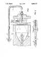
- FIG. 1is a general arrangement of a lamp-based laser simulator of the present invention.
- FIG. 2is an enlarged view of the coupling cone and connection to the fiber optic cable.
- a lamp-based laser simulator 10includes a conventional lamp 11 which may comprise an incandescent filament lamp, an arc lamp or a flash lamp.
- the light producing arc 12 in the arc lamp shownshould be relatively small, a size in the range of 0.5 to 3 millimeters generally being suitable.
- the lamp 11is positioned within an ellipsoidal reflector 13 which collects the light from the arc or filament source 12 and focuses it onto a distant point.
- the collection efficiency of the ellipsoidal reflector 13is about 50%.
- the light rays 14are focused on a distant point at an incidence angle A.
- a coupling cone 16is selected and positioned with its planar entrance face 17 at the focal point of the light.
- the coupling coneis preferably made of high transmittance optical glass with a circumferential cladding 18 of material having a low index of refraction to optimize internal reflection of light within the glass.
- the cone 16has a circular cross-section and is tapered to converge in the direction of light transmission and may have a frustoconical shape. However, the taper of the cone may be non-linear as well.
- the narrow opposite end of the coupling cone 16terminates in a planar exit face 20 which is parallel to the entrance face 17.
- the coupling cone 16functions to collect and condense the light into a narrow, intense beam to be launched into a fiber optic cable 21 coupled to the exit face 20 of the cone.
- the fiber optic cable 21may be coupled to the cone 16 with a number of suitable alternate connections.
- the choice and manner of making the connectionis, however, important because most losses in the system occur as a result of coupling efficiency.
- the exit face 20 of the conemay be attached in direct abutment to the adjacent face of the cable 21 with a suitable mechanical connector 15.
- Alternate connectionsmay be made by using an index matching solution or a coupling lens if the adjacent faces are spaced, or fusing the glass components together.
- the optical indices of the cone and cladding materialsdetermine the cone acceptance angle which should be equal to or larger than the angle of incidence A of the light.
- An angle of 30°is typical.
- the nature of the focused beam of lightshould be that it does not exceed the acceptance angle of the cone and does not magnify the source image of the arc 12 significantly.
- the gradual taper of the coupling cone 16is necessary to minimize losses.
- the light collected and condensed in the coneincreases the power per unit area available to be launched into the optical fiber 21 by approximately the ratio of the entrance to exit face areas.
- a 3 millimeter arc image from the lamp 11 directed into a coupling cone 16 with an entrance face 17 having a 3 millimeter diameter and an exit face 20 having a 1 millimeter diameterwill result in an increase in the light power of approximately one order of magnitude directed into a 1 millimeter diameter optical fiber 21.
- the final output of the system 10must be a focused beam of intense light carried by the small core fiber optic cable.
- Lamp light collected by the coupling cone 16 and channeled into the optical fiber 21will exhibit significant divergence as it exits the end of the fiber.
- the exit divergenceis greater than the acceptance angle by a factor proportional to the ratio of the entrance to exit face areas. Collimation is preserved through the use of special beam processing optics at the distal end of the fiber optic cable 21.
- a typical optical collimatorcomprises a lens system 22 which reduces light beam divergence and provides the required brightness at the target site.
- the lens system 22may comprises a collimating/converging lens pair 25 which may be conveniently mounted in a wand 26 for directing the output beam to the treatment site.
- the present inventionallows the simulation of a number of different types of lasers, depending on lamp choice and by the utilization of optical filtering.
- the tunable dye laseris used in many medical applications requiring wavelength selection in the ultraviolet-visible-near infrared spectral regions.
- an interference bandpass filter 23may be inserted into the system in front of the coupling cone 16.
- the filtermay conveniently consist of stack of several separate filters, such as a long pass filter and a short pass filter to define the bandwidth and a heat absorbing filter, preferably located nearest the lamp 11, to assist in preventing overheating of the other filters and the fiber optic components.
- a dye laser simulatorproviding therapeutic power of 1 to 2 watts at the fiber optic cable termination can be provided in a 1 mm or smaller diameter core fiber.
- the power densityexceeds that attainable in dye lasers currently in use.
- the apparatusmay include a shutter 24 disposed in front of the entrance face 17 of the coupling cone to permit selective transmission of light. Transmission may have to be prevented in order to control dosage or to comply with safety restrictions.
- CO 2 lasersare also widely used in medical applications, particularly in surgical applications requiring a cutting or burning action.
- One disadvantage of a CO 2 laser in such applicationsis the practical inability to utilize optical fiber transmission of the beam. Not only is the laser itself inherently expensive, but exotic waveguides or beam steering arms must be used with it in typical applications.
- Simulation of a CO 2 lasercan be attained through the use of a voltage-derated tungsten lamp with a peak output in the 2.8 to 3.2 micron wavelength band.
- a monochromatic CO 2 laser beamoperating at a wavelength of 10.6 microns, relies on the high absorption coefficient of water for its sharp cutting action.
- the absorption coefficient of wateris an order of magnitude greater at a wavelength of 2.6 microns than it is at 10.6 microns.
- a lower power CO 2 laser simulatorcan be more effective than a higher power CO 2 laser.
- a 2.5 watt laser simulatorwould be approximately equivalent to a 25 watt CO 2 laser.
- the laser simulatorutilizes the fiber optic link, making it much more flexible and less costly in its applications.
- Both the coupling cone 16 and optical fiber 21 previously describedmay be of monofilament construction. However, it is also possible to use multifilament bundles of smaller diameter fibers in either the cone or the fiber optic cable. Also, in lieu of the lens pair 25, used as the optical terminator at the end of the fiber optic cable, a graded index rod may be used. A graded index rod can provide the necessary collimation of the light exiting the optical fiber, but its use is somewhat limited at present because of high cost and lower power density rating.
- the lamp lightis collected and focused by the ellipsoidal reflector 13 with an efficiency of about 50%.
- the coupling cone 16condenses and channels the light into the fiber optic cable 21 with an efficiency of about 40%.
- the lamp-based laser simulator of the invention described herein, utilizing a fiber optic light delivery system,can provide a light intensity equivalent to a laser.
- the cost of a laser simulation systemis, however, much lower and it is more reliable in operation and is easier to use.
- the systemprovides an adjustable wavelength capability.
Landscapes
- Physics & Mathematics (AREA)
- General Physics & Mathematics (AREA)
- Optics & Photonics (AREA)
- Optical Couplings Of Light Guides (AREA)
Abstract
Description
Claims (14)
Priority Applications (1)
| Application Number | Priority Date | Filing Date | Title |
|---|---|---|---|
| US07/145,460US4860172A (en) | 1988-01-19 | 1988-01-19 | Lamp-based laser simulator |
Applications Claiming Priority (1)
| Application Number | Priority Date | Filing Date | Title |
|---|---|---|---|
| US07/145,460US4860172A (en) | 1988-01-19 | 1988-01-19 | Lamp-based laser simulator |
Publications (1)
| Publication Number | Publication Date |
|---|---|
| US4860172Atrue US4860172A (en) | 1989-08-22 |
Family
ID=22513230
Family Applications (1)
| Application Number | Title | Priority Date | Filing Date |
|---|---|---|---|
| US07/145,460Expired - Fee RelatedUS4860172A (en) | 1988-01-19 | 1988-01-19 | Lamp-based laser simulator |
Country Status (1)
| Country | Link |
|---|---|
| US (1) | US4860172A (en) |
Cited By (79)
| Publication number | Priority date | Publication date | Assignee | Title |
|---|---|---|---|---|
| US5006965A (en)* | 1990-03-09 | 1991-04-09 | Karl Storz Endoscopy-America, Inc. | Dimmer for fiber optic light transmission systems |
| US5060119A (en)* | 1988-11-10 | 1991-10-22 | Parthasarathy Mellapalayam R | Light pipe for decorative illumination |
| US5117312A (en)* | 1991-01-04 | 1992-05-26 | Fusion Systems Corporation | Apparatus including concave reflectors and a line of optical fibers |
| GB2250354A (en)* | 1990-08-18 | 1992-06-03 | Tbl Fibre Optics Limited | Light reflector |
| WO1993000551A1 (en)* | 1991-06-26 | 1993-01-07 | Shahriar Ghaffari | Lights-pumped high power medical system |
| US5178617A (en)* | 1991-07-09 | 1993-01-12 | Laserscope | System for controlled distribution of laser dosage |
| US5192279A (en)* | 1989-08-08 | 1993-03-09 | Samuels Mark A | Dental tissue cutting, drilling and fusing system |
| US5228109A (en)* | 1990-08-24 | 1993-07-13 | Matsushita Electric Industrial Co., Ltd. | Light beam heating apparatus and method utilizing a fiber optic cable with random fiber array |
| US5237634A (en)* | 1992-01-06 | 1993-08-17 | Follis Charles R | Fiber laser light projection system |
| EP0565331A2 (en) | 1992-04-09 | 1993-10-13 | ESC Medical Systems Ltd. | Therapeutic electromagnetic treatment |
| US5295052A (en)* | 1992-10-09 | 1994-03-15 | Luxtec Corporation | Light source assembly |
| FR2698972A1 (en)* | 1992-12-04 | 1994-06-10 | Chazallet Frederic | Apparatus for producing a monochromatic light beam |
| US5320618A (en)* | 1990-04-09 | 1994-06-14 | Morgan Gustafsson | Device for treatment of undesired skin disfigurements |
| FR2700201A1 (en)* | 1993-01-07 | 1994-07-08 | Croix Verte Ste Civile | Fiber optic distributor and light concentrator for supplying such an optical distributor. |
| US5335309A (en)* | 1991-08-29 | 1994-08-02 | Matsushita Electric Industrial Co., Ltd. | Light-beam heating apparatus |
| EP0610033A1 (en)* | 1993-02-01 | 1994-08-10 | General Electric Company | Collection optics for high brightness discharge light source |
| US5514126A (en)* | 1993-10-12 | 1996-05-07 | Prescott; Marvin | Fiber optic assembly for laser treatment system |
| AT401966B (en)* | 1994-11-17 | 1997-01-27 | Photonic Optische Geraete Gmbh | LIGHTING DEVICE |
| WO1997039277A1 (en)* | 1996-04-17 | 1997-10-23 | Dicon A/S | Method and apparatus for controlling light |
| ES2109156A1 (en)* | 1995-03-31 | 1998-01-01 | Julia Fernandez Rafael | Chromatic diffusion therapy equipment |
| US5760362A (en)* | 1993-09-08 | 1998-06-02 | Commissariat A L'energie Atomique | Apparatus for treating a material having a miniaturized photoionic head |
| US5769844A (en)* | 1991-06-26 | 1998-06-23 | Ghaffari; Shahriar | Conventional light-pumped high power system for medical applications |
| US5860723A (en)* | 1997-04-14 | 1999-01-19 | Transmatic, Inc. | Light engine with ellipsoidal reflector |
| US5885272A (en)* | 1990-10-30 | 1999-03-23 | Aita; Michael | System and method for percutaneous myocardial revascularization |
| EP0762809A3 (en)* | 1995-09-12 | 1999-10-13 | Denso Corporation | Discharge lamp device |
| WO2000044294A1 (en)* | 1999-01-29 | 2000-08-03 | Welch Allyn, Inc. | Apparatus and method of photo-specific tissue treatment |
| US6171332B1 (en) | 1992-10-23 | 2001-01-09 | Photo Therapeutics Limited | Light source |
| WO2000063731A3 (en)* | 1999-04-21 | 2001-02-08 | Cogent Light Tech | Method and apparatus for improving light power handling capabilities of polymer fibers |
| US6195477B1 (en)* | 1998-11-12 | 2001-02-27 | Delphi Technologies, Inc. | Hybrid fiber optic lighting distribution system |
| US6287300B1 (en) | 1996-12-09 | 2001-09-11 | Tokyo Iken Co., Ltd. | Optical fiber unit for medical examination and treatment and arm device for the optical fiber |
| US6375343B1 (en)* | 1998-08-17 | 2002-04-23 | Ushiodenki Kabushiki Kaisha | Light source device using optical fibers |
| US6413268B1 (en) | 2000-08-11 | 2002-07-02 | Raymond A. Hartman | Apparatus and method for targeted UV phototherapy of skin disorders |
| US20020091377A1 (en)* | 2000-01-25 | 2002-07-11 | Anderson R. Rox | Method and apparatus for medical treatment utilizing long duration electromagnetic radiation |
| US6454791B1 (en) | 1994-03-21 | 2002-09-24 | Marvin A. Prescott | Laser therapy for foot conditions |
| US20020161357A1 (en)* | 2000-12-28 | 2002-10-31 | Anderson R. Rox | Method and apparatus for EMR treatment |
| US6508813B1 (en) | 1996-12-02 | 2003-01-21 | Palomar Medical Technologies, Inc. | System for electromagnetic radiation dermatology and head for use therewith |
| US6511475B1 (en) | 1997-05-15 | 2003-01-28 | The General Hospital Corporation | Heads for dermatology treatment |
| US6514243B1 (en) | 1992-10-20 | 2003-02-04 | Lumenis Ltd. | Method and apparatus for electromagnetic treatment of the skin, including hair depilation |
| US6517532B1 (en) | 1997-05-15 | 2003-02-11 | Palomar Medical Technologies, Inc. | Light energy delivery head |
| US6605080B1 (en) | 1998-03-27 | 2003-08-12 | The General Hospital Corporation | Method and apparatus for the selective targeting of lipid-rich tissues |
| US6653618B2 (en) | 2000-04-28 | 2003-11-25 | Palomar Medical Technologies, Inc. | Contact detecting method and apparatus for an optical radiation handpiece |
| US20040015156A1 (en)* | 1998-12-03 | 2004-01-22 | Vasily David B. | Method and apparatus for laser removal of hair |
| US20040034319A1 (en)* | 2002-03-12 | 2004-02-19 | Palomar Medical Technologies, Inc. | Method and apparatus for hair growth management |
| US20040073079A1 (en)* | 2002-06-19 | 2004-04-15 | Palomar Medical Technologies, Inc. | Method and apparatus for treatment of cutaneous and subcutaneous conditions |
| US6723090B2 (en) | 2001-07-02 | 2004-04-20 | Palomar Medical Technologies, Inc. | Fiber laser device for medical/cosmetic procedures |
| US20040082941A1 (en)* | 1999-03-15 | 2004-04-29 | Connors Kevin P. | Tissue treatment device and method |
| US20040162596A1 (en)* | 2002-10-07 | 2004-08-19 | Palomar Medical Technologies, Inc. | Methods and apparatus for performing photobiostimulation |
| US20040162549A1 (en)* | 2002-11-12 | 2004-08-19 | Palomar Medical Technologies, Inc. | Method and apparatus for performing optical dermatology |
| WO2004110557A1 (en)* | 2003-06-16 | 2004-12-23 | National University Of Singapore | Apparatus and method for photothermal and photochemical medical treatments with incoherent light |
| US20050049658A1 (en)* | 2003-08-25 | 2005-03-03 | Connors Kevin P. | System and method for heating skin using light to provide tissue treatment |
| US20050137655A1 (en)* | 2003-12-22 | 2005-06-23 | Macfarland Dean A. | System and method for flexible architecture for dermatologic treatments utilizing multiple light sources |
| US7135033B2 (en) | 2002-05-23 | 2006-11-14 | Palomar Medical Technologies, Inc. | Phototreatment device for use with coolants and topical substances |
| US20060256544A1 (en)* | 2005-05-11 | 2006-11-16 | Irion Klaus M | Light system for photodynamic diagnosis and/or therapy |
| US20070038206A1 (en)* | 2004-12-09 | 2007-02-15 | Palomar Medical Technologies, Inc. | Photocosmetic device |
| US7204832B2 (en) | 1996-12-02 | 2007-04-17 | Pálomar Medical Technologies, Inc. | Cooling system for a photo cosmetic device |
| US7220254B2 (en) | 2003-12-31 | 2007-05-22 | Palomar Medical Technologies, Inc. | Dermatological treatment with visualization |
| US7274155B2 (en) | 2001-03-01 | 2007-09-25 | Palomar Medical Technologies, Inc. | Flash lamp drive circuit |
| US7291140B2 (en) | 2003-07-18 | 2007-11-06 | Cutera, Inc. | System and method for low average power dermatologic light treatment device |
| US7351252B2 (en) | 2002-06-19 | 2008-04-01 | Palomar Medical Technologies, Inc. | Method and apparatus for photothermal treatment of tissue at depth |
| US20080308753A1 (en)* | 2007-06-15 | 2008-12-18 | Stuba Robert M | Flexible infrared delivery apparatus and method |
| US7540869B2 (en) | 2001-12-27 | 2009-06-02 | Palomar Medical Technologies, Inc. | Method and apparatus for improved vascular related treatment |
| US20090248004A1 (en)* | 2008-02-28 | 2009-10-01 | Palomar Medical Technologies, Inc. | Systems and methods for treatment of soft tissue |
| US20090254076A1 (en)* | 2008-03-17 | 2009-10-08 | Palomar Medical Corporation | Method and apparatus for fractional deformation and treatment of tissue |
| US7722600B2 (en) | 2003-08-25 | 2010-05-25 | Cutera, Inc. | System and method for heating skin using light to provide tissue treatment |
| US20100145321A1 (en)* | 2000-12-28 | 2010-06-10 | Palomar Medical Technologies, Inc. | Methods and products for producing lattices of emr-treated islets in tissues, and uses therefor |
| US20100286673A1 (en)* | 2008-03-17 | 2010-11-11 | Palomar Medical Technologies, Inc. | Method and apparatus for treatment of tissue |
| US20100298744A1 (en)* | 2009-04-30 | 2010-11-25 | Palomar Medical Technologies, Inc. | System and method of treating tissue with ultrasound energy |
| US20110046523A1 (en)* | 2009-07-23 | 2011-02-24 | Palomar Medical Technologies, Inc. | Method for improvement of cellulite appearance |
| US8182473B2 (en) | 1999-01-08 | 2012-05-22 | Palomar Medical Technologies | Cooling system for a photocosmetic device |
| US8226696B1 (en) | 1997-06-16 | 2012-07-24 | Ellipse A/S | Light pulse generating apparatus and cosmetic and therapeutic phototreatment |
| US8268332B2 (en) | 2004-04-01 | 2012-09-18 | The General Hospital Corporation | Method for dermatological treatment using chromophores |
| US8346347B2 (en) | 2005-09-15 | 2013-01-01 | Palomar Medical Technologies, Inc. | Skin optical characterization device |
| US8915906B2 (en) | 2003-08-25 | 2014-12-23 | Cutera, Inc. | Method for treatment of post-partum abdominal skin redundancy or laxity |
| US9028536B2 (en) | 2006-08-02 | 2015-05-12 | Cynosure, Inc. | Picosecond laser apparatus and methods for its operation and use |
| US20160334071A1 (en)* | 2015-05-13 | 2016-11-17 | Stanley Electric Co., Ltd. | Light emitting apparatus and vehicle lighting fixture |
| US9780518B2 (en) | 2012-04-18 | 2017-10-03 | Cynosure, Inc. | Picosecond laser apparatus and methods for treating target tissues with same |
| US10245107B2 (en) | 2013-03-15 | 2019-04-02 | Cynosure, Inc. | Picosecond optical radiation systems and methods of use |
| US10434324B2 (en) | 2005-04-22 | 2019-10-08 | Cynosure, Llc | Methods and systems for laser treatment using non-uniform output beam |
| US11418000B2 (en) | 2018-02-26 | 2022-08-16 | Cynosure, Llc | Q-switched cavity dumped sub-nanosecond laser |
Citations (18)
| Publication number | Priority date | Publication date | Assignee | Title |
|---|---|---|---|---|
| US2981826A (en)* | 1959-10-27 | 1961-04-25 | Mattern John | Light equalizing device |
| US3327712A (en)* | 1961-09-15 | 1967-06-27 | Ira H Kaufman | Photocoagulation type fiber optical surgical device |
| US3432766A (en)* | 1963-02-01 | 1969-03-11 | Nat Res Dev | Apparatus for producing stimulated emission of radiation |
| US3516001A (en)* | 1966-12-01 | 1970-06-02 | American Optical Corp | Light-amplifying laser structures and the like |
| US3779628A (en)* | 1972-03-30 | 1973-12-18 | Corning Glass Works | Optical waveguide light source coupler |
| US3930504A (en)* | 1973-12-12 | 1976-01-06 | Clinitex, Inc. | Portable light coagulator |
| US4233493A (en)* | 1974-05-21 | 1980-11-11 | Nath Guenther | Apparatus for applying intense light radiation to a limited area |
| US4385344A (en)* | 1980-08-29 | 1983-05-24 | Dentsply Research & Development Corp. | Visible light apparatus for curing photo-curable compositions |
| US4411490A (en)* | 1980-08-18 | 1983-10-25 | Maurice Daniel | Apparatus for collecting, distributing and utilizing solar radiation |
| US4476519A (en)* | 1981-08-13 | 1984-10-09 | Olympus Optical Co., Ltd. | Annular illumination device |
| US4556875A (en)* | 1981-12-15 | 1985-12-03 | Matsushita Electric Industrial Co., Ltd. | Irradiated power monitoring system for optical fiber |
| US4576435A (en)* | 1982-08-05 | 1986-03-18 | Olympus Optical Co., Ltd. | Endoscope including a reflector related by an inequality for uniform light distribution |
| US4616899A (en)* | 1984-08-31 | 1986-10-14 | Gte Laboratories Incorporated | Methods of and apparatus for coupling an optoelectronic component to an optical fiber |
| US4627068A (en)* | 1984-06-13 | 1986-12-02 | The United States Of America As Represented By The Department Of Energy | Fiber optics interface for a dye laser oscillator and method |
| US4628416A (en)* | 1985-05-03 | 1986-12-09 | Coopervision, Inc. | Variable spot size illuminator with constant convergence angle |
| US4681396A (en)* | 1984-10-09 | 1987-07-21 | General Electric Company | High power laser energy delivery system |
| US4729621A (en)* | 1985-03-11 | 1988-03-08 | Shiley Inc. | Integral optical fiber coupler |
| US4807954A (en)* | 1985-02-16 | 1989-02-28 | Nippon Hoso Kyokai | Optical coupling device |
- 1988
- 1988-01-19USUS07/145,460patent/US4860172A/ennot_activeExpired - Fee Related
Patent Citations (18)
| Publication number | Priority date | Publication date | Assignee | Title |
|---|---|---|---|---|
| US2981826A (en)* | 1959-10-27 | 1961-04-25 | Mattern John | Light equalizing device |
| US3327712A (en)* | 1961-09-15 | 1967-06-27 | Ira H Kaufman | Photocoagulation type fiber optical surgical device |
| US3432766A (en)* | 1963-02-01 | 1969-03-11 | Nat Res Dev | Apparatus for producing stimulated emission of radiation |
| US3516001A (en)* | 1966-12-01 | 1970-06-02 | American Optical Corp | Light-amplifying laser structures and the like |
| US3779628A (en)* | 1972-03-30 | 1973-12-18 | Corning Glass Works | Optical waveguide light source coupler |
| US3930504A (en)* | 1973-12-12 | 1976-01-06 | Clinitex, Inc. | Portable light coagulator |
| US4233493A (en)* | 1974-05-21 | 1980-11-11 | Nath Guenther | Apparatus for applying intense light radiation to a limited area |
| US4411490A (en)* | 1980-08-18 | 1983-10-25 | Maurice Daniel | Apparatus for collecting, distributing and utilizing solar radiation |
| US4385344A (en)* | 1980-08-29 | 1983-05-24 | Dentsply Research & Development Corp. | Visible light apparatus for curing photo-curable compositions |
| US4476519A (en)* | 1981-08-13 | 1984-10-09 | Olympus Optical Co., Ltd. | Annular illumination device |
| US4556875A (en)* | 1981-12-15 | 1985-12-03 | Matsushita Electric Industrial Co., Ltd. | Irradiated power monitoring system for optical fiber |
| US4576435A (en)* | 1982-08-05 | 1986-03-18 | Olympus Optical Co., Ltd. | Endoscope including a reflector related by an inequality for uniform light distribution |
| US4627068A (en)* | 1984-06-13 | 1986-12-02 | The United States Of America As Represented By The Department Of Energy | Fiber optics interface for a dye laser oscillator and method |
| US4616899A (en)* | 1984-08-31 | 1986-10-14 | Gte Laboratories Incorporated | Methods of and apparatus for coupling an optoelectronic component to an optical fiber |
| US4681396A (en)* | 1984-10-09 | 1987-07-21 | General Electric Company | High power laser energy delivery system |
| US4807954A (en)* | 1985-02-16 | 1989-02-28 | Nippon Hoso Kyokai | Optical coupling device |
| US4729621A (en)* | 1985-03-11 | 1988-03-08 | Shiley Inc. | Integral optical fiber coupler |
| US4628416A (en)* | 1985-05-03 | 1986-12-09 | Coopervision, Inc. | Variable spot size illuminator with constant convergence angle |
Cited By (150)
| Publication number | Priority date | Publication date | Assignee | Title |
|---|---|---|---|---|
| US5060119A (en)* | 1988-11-10 | 1991-10-22 | Parthasarathy Mellapalayam R | Light pipe for decorative illumination |
| US5192279A (en)* | 1989-08-08 | 1993-03-09 | Samuels Mark A | Dental tissue cutting, drilling and fusing system |
| US5006965A (en)* | 1990-03-09 | 1991-04-09 | Karl Storz Endoscopy-America, Inc. | Dimmer for fiber optic light transmission systems |
| US5320618A (en)* | 1990-04-09 | 1994-06-14 | Morgan Gustafsson | Device for treatment of undesired skin disfigurements |
| GB2250354A (en)* | 1990-08-18 | 1992-06-03 | Tbl Fibre Optics Limited | Light reflector |
| US5228109A (en)* | 1990-08-24 | 1993-07-13 | Matsushita Electric Industrial Co., Ltd. | Light beam heating apparatus and method utilizing a fiber optic cable with random fiber array |
| US5885272A (en)* | 1990-10-30 | 1999-03-23 | Aita; Michael | System and method for percutaneous myocardial revascularization |
| US5117312A (en)* | 1991-01-04 | 1992-05-26 | Fusion Systems Corporation | Apparatus including concave reflectors and a line of optical fibers |
| WO1993000551A1 (en)* | 1991-06-26 | 1993-01-07 | Shahriar Ghaffari | Lights-pumped high power medical system |
| AU673982B2 (en)* | 1991-06-26 | 1996-12-05 | Shahriar Ghaffari | Lights-pumped high power medical system |
| US5769844A (en)* | 1991-06-26 | 1998-06-23 | Ghaffari; Shahriar | Conventional light-pumped high power system for medical applications |
| US5178617A (en)* | 1991-07-09 | 1993-01-12 | Laserscope | System for controlled distribution of laser dosage |
| US5335309A (en)* | 1991-08-29 | 1994-08-02 | Matsushita Electric Industrial Co., Ltd. | Light-beam heating apparatus |
| US5237634A (en)* | 1992-01-06 | 1993-08-17 | Follis Charles R | Fiber laser light projection system |
| EP0565331A2 (en) | 1992-04-09 | 1993-10-13 | ESC Medical Systems Ltd. | Therapeutic electromagnetic treatment |
| EP1078605A3 (en)* | 1992-04-09 | 2001-08-08 | ESC Medical Systems Ltd. | Device for therapeutic electromagnetic treatment |
| EP1078604A3 (en)* | 1992-04-09 | 2001-08-08 | ESC Medical Systems Ltd. | Device for therapeutic electromagnetic treatment |
| EP0565331B1 (en)* | 1992-04-09 | 2001-01-24 | ESC Medical Systems Ltd. | Device for therapeutic electromagnetic treatment |
| US5295052A (en)* | 1992-10-09 | 1994-03-15 | Luxtec Corporation | Light source assembly |
| US20030069567A1 (en)* | 1992-10-20 | 2003-04-10 | Shimon Eckhouse | Method and apparatus for electromagnetic treatment of the skin, including hair depilation |
| US6514243B1 (en) | 1992-10-20 | 2003-02-04 | Lumenis Ltd. | Method and apparatus for electromagnetic treatment of the skin, including hair depilation |
| US7108689B2 (en) | 1992-10-20 | 2006-09-19 | Lumenis Ltd | Method and apparatus for electromagnetic treatment of the skin, including hair depilation |
| US6461866B1 (en) | 1992-10-23 | 2002-10-08 | Photo Therapeutics Limited | In vitro photodynamic therapy using non laser light |
| US6171332B1 (en) | 1992-10-23 | 2001-01-09 | Photo Therapeutics Limited | Light source |
| FR2698972A1 (en)* | 1992-12-04 | 1994-06-10 | Chazallet Frederic | Apparatus for producing a monochromatic light beam |
| EP0601946A1 (en)* | 1992-12-04 | 1994-06-15 | Frédéric Chazallet | Device for producing a monochromatic light beam |
| US5453883A (en)* | 1992-12-04 | 1995-09-26 | Chazallet; Frederic | Apparatus for producing a monochromatic light beam |
| FR2700201A1 (en)* | 1993-01-07 | 1994-07-08 | Croix Verte Ste Civile | Fiber optic distributor and light concentrator for supplying such an optical distributor. |
| EP0610033A1 (en)* | 1993-02-01 | 1994-08-10 | General Electric Company | Collection optics for high brightness discharge light source |
| US5760362A (en)* | 1993-09-08 | 1998-06-02 | Commissariat A L'energie Atomique | Apparatus for treating a material having a miniaturized photoionic head |
| US5514126A (en)* | 1993-10-12 | 1996-05-07 | Prescott; Marvin | Fiber optic assembly for laser treatment system |
| US6454791B1 (en) | 1994-03-21 | 2002-09-24 | Marvin A. Prescott | Laser therapy for foot conditions |
| AT401966B (en)* | 1994-11-17 | 1997-01-27 | Photonic Optische Geraete Gmbh | LIGHTING DEVICE |
| ES2109156A1 (en)* | 1995-03-31 | 1998-01-01 | Julia Fernandez Rafael | Chromatic diffusion therapy equipment |
| EP0762809A3 (en)* | 1995-09-12 | 1999-10-13 | Denso Corporation | Discharge lamp device |
| WO1997039277A1 (en)* | 1996-04-17 | 1997-10-23 | Dicon A/S | Method and apparatus for controlling light |
| US6296383B1 (en)* | 1996-04-17 | 2001-10-02 | Dicon A/S | Method and apparatus for controlling light |
| EP1338846A3 (en)* | 1996-04-17 | 2004-03-03 | Dicon A/S | Method and apparatus for controlling light |
| US20090137995A1 (en)* | 1996-12-02 | 2009-05-28 | Palomar Medical Technologies, Inc. | System For Electromagnetic Radiation Dermatology And Head For Use Therewith |
| US8328794B2 (en) | 1996-12-02 | 2012-12-11 | Palomar Medical Technologies, Inc. | System for electromagnetic radiation dermatology and head for use therewith |
| US7431719B2 (en) | 1996-12-02 | 2008-10-07 | Palomar Medical Technologies, Inc. | System for electromagnetic radiation dermatology and head for use therewith |
| US7204832B2 (en) | 1996-12-02 | 2007-04-17 | Pálomar Medical Technologies, Inc. | Cooling system for a photo cosmetic device |
| US6878144B2 (en) | 1996-12-02 | 2005-04-12 | Palomar Medical Technologies, Inc. | System for electromagnetic radiation dermatology and head for use therewith |
| US6508813B1 (en) | 1996-12-02 | 2003-01-21 | Palomar Medical Technologies, Inc. | System for electromagnetic radiation dermatology and head for use therewith |
| US6287300B1 (en) | 1996-12-09 | 2001-09-11 | Tokyo Iken Co., Ltd. | Optical fiber unit for medical examination and treatment and arm device for the optical fiber |
| US6496620B1 (en) | 1997-03-27 | 2002-12-17 | Wavien, Inc. | Method and apparatus for improving power handling capabilities of polymer fibers |
| US5860723A (en)* | 1997-04-14 | 1999-01-19 | Transmatic, Inc. | Light engine with ellipsoidal reflector |
| US8002768B1 (en) | 1997-05-15 | 2011-08-23 | Palomar Medical Technologies, Inc. | Light energy delivery head |
| US6974451B2 (en) | 1997-05-15 | 2005-12-13 | Palomar Medical Technologies, Inc. | Light energy delivery head |
| US6976985B2 (en) | 1997-05-15 | 2005-12-20 | Palomar Medical Technologies, Inc. | Light energy delivery head |
| US7763016B2 (en) | 1997-05-15 | 2010-07-27 | Palomar Medical Technologies, Inc. | Light energy delivery head |
| US20030195494A1 (en)* | 1997-05-15 | 2003-10-16 | Altshuler Gregory B. | Light energy delivery head |
| US7077840B2 (en) | 1997-05-15 | 2006-07-18 | Palomar Medical Technologies, Inc. | Heads for dermatology treatment |
| US8109924B2 (en) | 1997-05-15 | 2012-02-07 | Palomar Medical Technologies, Inc. | Heads for dermatology treatment |
| US6663620B2 (en) | 1997-05-15 | 2003-12-16 | Palomar Medical Technologies, Inc. | Light energy delivery head |
| US6517532B1 (en) | 1997-05-15 | 2003-02-11 | Palomar Medical Technologies, Inc. | Light energy delivery head |
| US8328796B2 (en) | 1997-05-15 | 2012-12-11 | Palomar Medical Technologies, Inc. | Light energy delivery head |
| US6511475B1 (en) | 1997-05-15 | 2003-01-28 | The General Hospital Corporation | Heads for dermatology treatment |
| US7935107B2 (en) | 1997-05-15 | 2011-05-03 | Palomar Medical Technologies, Inc. | Heads for dermatology treatment |
| US20030055414A1 (en)* | 1997-05-15 | 2003-03-20 | Altshuler Gregory B. | Heads for dermatology treatment |
| US7758621B2 (en) | 1997-05-15 | 2010-07-20 | Palomar Medical Technologies, Inc. | Method and apparatus for therapeutic EMR treatment on the skin |
| US8226696B1 (en) | 1997-06-16 | 2012-07-24 | Ellipse A/S | Light pulse generating apparatus and cosmetic and therapeutic phototreatment |
| US20040034341A1 (en)* | 1998-03-27 | 2004-02-19 | Palomar Medical Technologies, Inc. | Method and apparatus for the selective targeting of lipid-rich tissues |
| US20030199859A1 (en)* | 1998-03-27 | 2003-10-23 | Altshuler Gregory B. | Method and apparatus for the selective targeting of lipid-rich tissues |
| US6605080B1 (en) | 1998-03-27 | 2003-08-12 | The General Hospital Corporation | Method and apparatus for the selective targeting of lipid-rich tissues |
| US7060061B2 (en) | 1998-03-27 | 2006-06-13 | Palomar Medical Technologies, Inc. | Method and apparatus for the selective targeting of lipid-rich tissues |
| US6375343B1 (en)* | 1998-08-17 | 2002-04-23 | Ushiodenki Kabushiki Kaisha | Light source device using optical fibers |
| US6195477B1 (en)* | 1998-11-12 | 2001-02-27 | Delphi Technologies, Inc. | Hybrid fiber optic lighting distribution system |
| US20040015156A1 (en)* | 1998-12-03 | 2004-01-22 | Vasily David B. | Method and apparatus for laser removal of hair |
| US7029469B2 (en) | 1998-12-03 | 2006-04-18 | Palomar Medical Technologies, Inc. | Method and apparatus for laser removal of hair |
| US8182473B2 (en) | 1999-01-08 | 2012-05-22 | Palomar Medical Technologies | Cooling system for a photocosmetic device |
| WO2000044294A1 (en)* | 1999-01-29 | 2000-08-03 | Welch Allyn, Inc. | Apparatus and method of photo-specific tissue treatment |
| US20060122585A1 (en)* | 1999-03-15 | 2006-06-08 | Acme Medical, Inc. | Tissue treatment system |
| US7465307B2 (en) | 1999-03-15 | 2008-12-16 | Cutera, Inc. | Tissue treatment system |
| US7041094B2 (en) | 1999-03-15 | 2006-05-09 | Cutera, Inc. | Tissue treatment device and method |
| US20040082941A1 (en)* | 1999-03-15 | 2004-04-29 | Connors Kevin P. | Tissue treatment device and method |
| US20070208326A1 (en)* | 1999-03-15 | 2007-09-06 | Connors Kevin P | Tissue treatment system |
| US7618414B2 (en) | 1999-03-15 | 2009-11-17 | Cutera, Inc. | Tissue treatment system |
| WO2000063731A3 (en)* | 1999-04-21 | 2001-02-08 | Cogent Light Tech | Method and apparatus for improving light power handling capabilities of polymer fibers |
| US20020091377A1 (en)* | 2000-01-25 | 2002-07-11 | Anderson R. Rox | Method and apparatus for medical treatment utilizing long duration electromagnetic radiation |
| US6653618B2 (en) | 2000-04-28 | 2003-11-25 | Palomar Medical Technologies, Inc. | Contact detecting method and apparatus for an optical radiation handpiece |
| US6413268B1 (en) | 2000-08-11 | 2002-07-02 | Raymond A. Hartman | Apparatus and method for targeted UV phototherapy of skin disorders |
| US20020161357A1 (en)* | 2000-12-28 | 2002-10-31 | Anderson R. Rox | Method and apparatus for EMR treatment |
| US20100145321A1 (en)* | 2000-12-28 | 2010-06-10 | Palomar Medical Technologies, Inc. | Methods and products for producing lattices of emr-treated islets in tissues, and uses therefor |
| US6997923B2 (en) | 2000-12-28 | 2006-02-14 | Palomar Medical Technologies, Inc. | Method and apparatus for EMR treatment |
| US7274155B2 (en) | 2001-03-01 | 2007-09-25 | Palomar Medical Technologies, Inc. | Flash lamp drive circuit |
| US7531967B2 (en) | 2001-03-01 | 2009-05-12 | Palomar Medical Technologies, Inc. | Flashlamp drive circuit |
| US6723090B2 (en) | 2001-07-02 | 2004-04-20 | Palomar Medical Technologies, Inc. | Fiber laser device for medical/cosmetic procedures |
| US20090149844A1 (en)* | 2001-12-27 | 2009-06-11 | Palomar Medical Technologies, Inc. | Method And Apparatus For Improved Vascular Related Treatment |
| US7540869B2 (en) | 2001-12-27 | 2009-06-02 | Palomar Medical Technologies, Inc. | Method and apparatus for improved vascular related treatment |
| US7044959B2 (en) | 2002-03-12 | 2006-05-16 | Palomar Medical Technologies, Inc. | Method and apparatus for hair growth management |
| US20040034319A1 (en)* | 2002-03-12 | 2004-02-19 | Palomar Medical Technologies, Inc. | Method and apparatus for hair growth management |
| US20110184334A1 (en)* | 2002-05-23 | 2011-07-28 | Palomar Medical Technologies, Inc. | Phototreatment device for use with coolants and topical substances |
| US7942916B2 (en) | 2002-05-23 | 2011-05-17 | Palomar Medical Technologies, Inc. | Phototreatment device for use with coolants and topical substances |
| US7942915B2 (en) | 2002-05-23 | 2011-05-17 | Palomar Medical Technologies, Inc. | Phototreatment device for use with coolants |
| US7135033B2 (en) | 2002-05-23 | 2006-11-14 | Palomar Medical Technologies, Inc. | Phototreatment device for use with coolants and topical substances |
| US10556123B2 (en) | 2002-06-19 | 2020-02-11 | Palomar Medical Technologies, Llc | Method and apparatus for treatment of cutaneous and subcutaneous conditions |
| US8915948B2 (en) | 2002-06-19 | 2014-12-23 | Palomar Medical Technologies, Llc | Method and apparatus for photothermal treatment of tissue at depth |
| US10500413B2 (en) | 2002-06-19 | 2019-12-10 | Palomar Medical Technologies, Llc | Method and apparatus for treatment of cutaneous and subcutaneous conditions |
| US7351252B2 (en) | 2002-06-19 | 2008-04-01 | Palomar Medical Technologies, Inc. | Method and apparatus for photothermal treatment of tissue at depth |
| US7276058B2 (en) | 2002-06-19 | 2007-10-02 | Palomar Medical Technologies, Inc. | Method and apparatus for treatment of cutaneous and subcutaneous conditions |
| US20040073079A1 (en)* | 2002-06-19 | 2004-04-15 | Palomar Medical Technologies, Inc. | Method and apparatus for treatment of cutaneous and subcutaneous conditions |
| US20040162596A1 (en)* | 2002-10-07 | 2004-08-19 | Palomar Medical Technologies, Inc. | Methods and apparatus for performing photobiostimulation |
| US20040162549A1 (en)* | 2002-11-12 | 2004-08-19 | Palomar Medical Technologies, Inc. | Method and apparatus for performing optical dermatology |
| WO2004110557A1 (en)* | 2003-06-16 | 2004-12-23 | National University Of Singapore | Apparatus and method for photothermal and photochemical medical treatments with incoherent light |
| US7291140B2 (en) | 2003-07-18 | 2007-11-06 | Cutera, Inc. | System and method for low average power dermatologic light treatment device |
| US7722600B2 (en) | 2003-08-25 | 2010-05-25 | Cutera, Inc. | System and method for heating skin using light to provide tissue treatment |
| US8915906B2 (en) | 2003-08-25 | 2014-12-23 | Cutera, Inc. | Method for treatment of post-partum abdominal skin redundancy or laxity |
| US8870856B2 (en) | 2003-08-25 | 2014-10-28 | Cutera, Inc. | Method for heating skin using light to provide tissue treatment |
| US20050049658A1 (en)* | 2003-08-25 | 2005-03-03 | Connors Kevin P. | System and method for heating skin using light to provide tissue treatment |
| US7326199B2 (en) | 2003-12-22 | 2008-02-05 | Cutera, Inc. | System and method for flexible architecture for dermatologic treatments utilizing multiple light sources |
| US7780652B2 (en) | 2003-12-22 | 2010-08-24 | Cutera, Inc. | System and method for flexible architecture for dermatologic treatments utilizing multiple light sources |
| US20050137655A1 (en)* | 2003-12-22 | 2005-06-23 | Macfarland Dean A. | System and method for flexible architecture for dermatologic treatments utilizing multiple light sources |
| US7220254B2 (en) | 2003-12-31 | 2007-05-22 | Palomar Medical Technologies, Inc. | Dermatological treatment with visualization |
| US7309335B2 (en) | 2003-12-31 | 2007-12-18 | Palomar Medical Technologies, Inc. | Dermatological treatment with visualization |
| US9452013B2 (en) | 2004-04-01 | 2016-09-27 | The General Hospital Corporation | Apparatus for dermatological treatment using chromophores |
| US8268332B2 (en) | 2004-04-01 | 2012-09-18 | The General Hospital Corporation | Method for dermatological treatment using chromophores |
| US20070038206A1 (en)* | 2004-12-09 | 2007-02-15 | Palomar Medical Technologies, Inc. | Photocosmetic device |
| US10434324B2 (en) | 2005-04-22 | 2019-10-08 | Cynosure, Llc | Methods and systems for laser treatment using non-uniform output beam |
| US8657862B2 (en)* | 2005-05-11 | 2014-02-25 | Karl Storz Gmbh & Co. Kg | Light system for photodynamic diagnosis and/or therapy |
| US20060256544A1 (en)* | 2005-05-11 | 2006-11-16 | Irion Klaus M | Light system for photodynamic diagnosis and/or therapy |
| US8346347B2 (en) | 2005-09-15 | 2013-01-01 | Palomar Medical Technologies, Inc. | Skin optical characterization device |
| US11712299B2 (en) | 2006-08-02 | 2023-08-01 | Cynosure, LLC. | Picosecond laser apparatus and methods for its operation and use |
| US10849687B2 (en) | 2006-08-02 | 2020-12-01 | Cynosure, Llc | Picosecond laser apparatus and methods for its operation and use |
| US10966785B2 (en) | 2006-08-02 | 2021-04-06 | Cynosure, Llc | Picosecond laser apparatus and methods for its operation and use |
| US9028536B2 (en) | 2006-08-02 | 2015-05-12 | Cynosure, Inc. | Picosecond laser apparatus and methods for its operation and use |
| US7977658B2 (en)* | 2007-06-15 | 2011-07-12 | Precision Endoscopic Technologies | Flexible infrared delivery apparatus and method |
| US20080308753A1 (en)* | 2007-06-15 | 2008-12-18 | Stuba Robert M | Flexible infrared delivery apparatus and method |
| US20090248004A1 (en)* | 2008-02-28 | 2009-10-01 | Palomar Medical Technologies, Inc. | Systems and methods for treatment of soft tissue |
| US20100286673A1 (en)* | 2008-03-17 | 2010-11-11 | Palomar Medical Technologies, Inc. | Method and apparatus for treatment of tissue |
| US20090254076A1 (en)* | 2008-03-17 | 2009-10-08 | Palomar Medical Corporation | Method and apparatus for fractional deformation and treatment of tissue |
| US20100298744A1 (en)* | 2009-04-30 | 2010-11-25 | Palomar Medical Technologies, Inc. | System and method of treating tissue with ultrasound energy |
| US20110046523A1 (en)* | 2009-07-23 | 2011-02-24 | Palomar Medical Technologies, Inc. | Method for improvement of cellulite appearance |
| US9919168B2 (en) | 2009-07-23 | 2018-03-20 | Palomar Medical Technologies, Inc. | Method for improvement of cellulite appearance |
| US11095087B2 (en) | 2012-04-18 | 2021-08-17 | Cynosure, Llc | Picosecond laser apparatus and methods for treating target tissues with same |
| US11664637B2 (en) | 2012-04-18 | 2023-05-30 | Cynosure, Llc | Picosecond laser apparatus and methods for treating target tissues with same |
| US12431683B2 (en) | 2012-04-18 | 2025-09-30 | Cynosure, Llc | Picosecond laser apparatus and methods for treating target tissues with same |
| US10581217B2 (en) | 2012-04-18 | 2020-03-03 | Cynosure, Llc | Picosecond laser apparatus and methods for treating target tissues with same |
| US12068571B2 (en) | 2012-04-18 | 2024-08-20 | Cynosure, Llc | Picosecond laser apparatus and methods for treating target tissues with same |
| US10305244B2 (en) | 2012-04-18 | 2019-05-28 | Cynosure, Llc | Picosecond laser apparatus and methods for treating target tissues with same |
| US9780518B2 (en) | 2012-04-18 | 2017-10-03 | Cynosure, Inc. | Picosecond laser apparatus and methods for treating target tissues with same |
| US11446086B2 (en) | 2013-03-15 | 2022-09-20 | Cynosure, Llc | Picosecond optical radiation systems and methods of use |
| US10245107B2 (en) | 2013-03-15 | 2019-04-02 | Cynosure, Inc. | Picosecond optical radiation systems and methods of use |
| US10765478B2 (en) | 2013-03-15 | 2020-09-08 | Cynosurce, Llc | Picosecond optical radiation systems and methods of use |
| US12193734B2 (en) | 2013-03-15 | 2025-01-14 | Cynosure, Llc | Picosecond optical radiation systems and methods of use |
| US10285757B2 (en) | 2013-03-15 | 2019-05-14 | Cynosure, Llc | Picosecond optical radiation systems and methods of use |
| US9897273B2 (en)* | 2015-05-13 | 2018-02-20 | Stanley Electric Co., Ltd. | Light emitting apparatus and vehicle lighting fixture |
| US20160334071A1 (en)* | 2015-05-13 | 2016-11-17 | Stanley Electric Co., Ltd. | Light emitting apparatus and vehicle lighting fixture |
| US11418000B2 (en) | 2018-02-26 | 2022-08-16 | Cynosure, Llc | Q-switched cavity dumped sub-nanosecond laser |
| US11791603B2 (en) | 2018-02-26 | 2023-10-17 | Cynosure, LLC. | Q-switched cavity dumped sub-nanosecond laser |
Similar Documents
| Publication | Publication Date | Title |
|---|---|---|
| US4860172A (en) | Lamp-based laser simulator | |
| US5461692A (en) | Multimode optical fiber coupling apparatus and method of transmitting laser radiation using same | |
| US6385371B1 (en) | Optical system including coupling for transmitting light between a single fiber light guide and multiple single fiber light guides | |
| US5179610A (en) | Connector for coupling of laser energy | |
| US6246817B1 (en) | Optical fiber with numerical aperture compression | |
| JPH04288510A (en) | Structure of optical waveguide having bragg diffraction grating provided therein for changing optical direction | |
| JPH02150806A (en) | Optical fiber bundle for high-illuminance electromagnetic ray transmission | |
| US4054364A (en) | Apparatus for transmitting light through Cassegrain optics | |
| JP3070405B2 (en) | Endoscope light guide connector | |
| US20060233492A1 (en) | Optical beam combiner/concentrator | |
| US11635604B2 (en) | Luminous flux collector for directing light into a light-diffusing fiber | |
| KR20030068132A (en) | Light condensing and collecting systems using lensed light pipes | |
| EP0978748B1 (en) | Multiple light source unit and optical system using the same | |
| KR20020012555A (en) | Improved coupling of light from a small arc lamp to a larger target | |
| JPH06511594A (en) | Optical pump type high output medical system | |
| WO1992008427A3 (en) | Laser surgical probe | |
| Ward | Molding of laser energy by shaped optic fiber tips | |
| JPH0256504A (en) | How to assemble a flexible guide for infrared energy | |
| WO2023058700A1 (en) | Beam shaping lens, beam shaping element, light source device for endoscope, and endoscope | |
| EP1215520B1 (en) | Optical arrangement for the collection of light | |
| US6318885B1 (en) | Method and apparatus for coupling light and producing magnified images using an asymmetrical ellipsoid reflective surface | |
| RU2803715C1 (en) | Device for input of incoherent radiation into light guide | |
| JPH0722601B2 (en) | Laser equipment | |
| JPH05345039A (en) | Laser probe | |
| WO2000077446A2 (en) | Optical apparatus |
Legal Events
| Date | Code | Title | Description |
|---|---|---|---|
| AS | Assignment | Owner name:BIOTRONICS ASSOCIATES, INC., WAUWATOSA, WI A CORP. Free format text:ASSIGNMENT OF ASSIGNORS INTEREST.;ASSIGNORS:SCHLAGER, KENNETH J.;GORSKI, STEPHEN H.;REEL/FRAME:004836/0072 Effective date:19880111 Owner name:BIOTRONICS ASSOCIATES, INC., A CORP. OF WI, WISCON Free format text:ASSIGNMENT OF ASSIGNORS INTEREST;ASSIGNORS:SCHLAGER, KENNETH J.;GORSKI, STEPHEN H.;REEL/FRAME:004836/0072 Effective date:19880111 | |
| AS | Assignment | Owner name:BIOTRONICS TECHNOLOGIES, INC., 12020 WEST RIPLEY A Free format text:ASSIGNMENT OF ASSIGNORS INTEREST.;ASSIGNOR:BIOTRONICS ASSOCIATES, INC.;REEL/FRAME:005145/0288 Effective date:19890712 | |
| AS | Assignment | Owner name:Z.L. COMMERCIAL SERVICES, INC., A CORP. OF WI Free format text:SECURITY INTEREST;ASSIGNOR:BIOTRONICS ASSOCIATES, INC.,;REEL/FRAME:005134/0812 Effective date:19890712 | |
| REMI | Maintenance fee reminder mailed | ||
| FPAY | Fee payment | Year of fee payment:4 | |
| SULP | Surcharge for late payment | ||
| AS | Assignment | Owner name:TERRIZZI, CHARLES G. Free format text:COLLATERAL ASSIGNMENT;ASSIGNOR:BIOTRONICS TECHNOLOGIES, INC.;REEL/FRAME:007317/0479 Effective date:19950111 Owner name:TERRIZZI, JAN M. Free format text:COLLATERAL ASSIGNMENT;ASSIGNOR:BIOTRONICS TECHNOLOGIES, INC.;REEL/FRAME:007317/0479 Effective date:19950111 | |
| FEPP | Fee payment procedure | Free format text:PAYOR NUMBER ASSIGNED (ORIGINAL EVENT CODE: ASPN); ENTITY STATUS OF PATENT OWNER: SMALL ENTITY | |
| FPAY | Fee payment | Year of fee payment:8 | |
| REMI | Maintenance fee reminder mailed | ||
| LAPS | Lapse for failure to pay maintenance fees | ||
| FP | Lapsed due to failure to pay maintenance fee | Effective date:20010822 | |
| STCH | Information on status: patent discontinuation | Free format text:PATENT EXPIRED DUE TO NONPAYMENT OF MAINTENANCE FEES UNDER 37 CFR 1.362 |