US4859806A - Discretionary interconnect - Google Patents
Discretionary interconnectDownload PDFInfo
- Publication number
- US4859806A US4859806AUS07/194,666US19466688AUS4859806AUS 4859806 AUS4859806 AUS 4859806AUS 19466688 AUS19466688 AUS 19466688AUS 4859806 AUS4859806 AUS 4859806A
- Authority
- US
- United States
- Prior art keywords
- wires
- interconnect
- vias
- discretionary
- trace
- Prior art date
- Legal status (The legal status is an assumption and is not a legal conclusion. Google has not performed a legal analysis and makes no representation as to the accuracy of the status listed.)
- Expired - Lifetime
Links
- 238000000034methodMethods0.000claimsabstractdescription34
- 230000008569processEffects0.000claimsabstractdescription14
- 238000005304joiningMethods0.000claimsdescription11
- 239000004020conductorSubstances0.000abstractdescription29
- 238000003491arrayMethods0.000abstractdescription8
- 239000000758substrateSubstances0.000description23
- 238000013461designMethods0.000description15
- 239000000463materialSubstances0.000description15
- RYGMFSIKBFXOCR-UHFFFAOYSA-NCopperChemical compound[Cu]RYGMFSIKBFXOCR-UHFFFAOYSA-N0.000description10
- 239000004593EpoxySubstances0.000description10
- 229910052802copperInorganic materials0.000description10
- 239000010949copperSubstances0.000description10
- 229910000679solderInorganic materials0.000description10
- 238000004519manufacturing processMethods0.000description9
- 239000004642PolyimideSubstances0.000description8
- 230000005540biological transmissionEffects0.000description8
- 229920001721polyimidePolymers0.000description8
- 238000005516engineering processMethods0.000description7
- 238000009413insulationMethods0.000description7
- 238000010276constructionMethods0.000description6
- 229910000497AmalgamInorganic materials0.000description4
- 238000013459approachMethods0.000description4
- 230000003993interactionEffects0.000description4
- 229910052751metalInorganic materials0.000description4
- 239000002184metalSubstances0.000description4
- 238000007747platingMethods0.000description4
- 239000000126substanceSubstances0.000description4
- 230000008901benefitEffects0.000description3
- 230000008859changeEffects0.000description3
- 125000003700epoxy groupChemical group0.000description3
- 239000011888foilSubstances0.000description3
- -1for examplePolymers0.000description3
- 229920000647polyepoxidePolymers0.000description3
- 238000012545processingMethods0.000description3
- 230000005855radiationEffects0.000description3
- 235000012431wafersNutrition0.000description3
- BQCADISMDOOEFD-UHFFFAOYSA-NSilverChemical compound[Ag]BQCADISMDOOEFD-UHFFFAOYSA-N0.000description2
- 229910052782aluminiumInorganic materials0.000description2
- XAGFODPZIPBFFR-UHFFFAOYSA-NaluminiumChemical compound[Al]XAGFODPZIPBFFR-UHFFFAOYSA-N0.000description2
- 238000005520cutting processMethods0.000description2
- 238000010586diagramMethods0.000description2
- 239000003989dielectric materialSubstances0.000description2
- 230000000694effectsEffects0.000description2
- 238000005530etchingMethods0.000description2
- 230000008020evaporationEffects0.000description2
- 238000001704evaporationMethods0.000description2
- PCHJSUWPFVWCPO-UHFFFAOYSA-NgoldChemical compound[Au]PCHJSUWPFVWCPO-UHFFFAOYSA-N0.000description2
- 229910052737goldInorganic materials0.000description2
- 239000010931goldSubstances0.000description2
- 238000010438heat treatmentMethods0.000description2
- 238000003754machiningMethods0.000description2
- 238000004080punchingMethods0.000description2
- 238000000926separation methodMethods0.000description2
- 229910052710siliconInorganic materials0.000description2
- 239000010703siliconSubstances0.000description2
- 229910052709silverInorganic materials0.000description2
- 239000004332silverSubstances0.000description2
- 238000005476solderingMethods0.000description2
- 238000004544sputter depositionMethods0.000description2
- 238000003466weldingMethods0.000description2
- 229910000906BronzeInorganic materials0.000description1
- CYTYCFOTNPOANT-UHFFFAOYSA-NPerchloroethyleneChemical compoundClC(Cl)=C(Cl)ClCYTYCFOTNPOANT-UHFFFAOYSA-N0.000description1
- 239000004698PolyethyleneSubstances0.000description1
- 238000010521absorption reactionMethods0.000description1
- 239000000654additiveSubstances0.000description1
- 230000000996additive effectEffects0.000description1
- 238000004026adhesive bondingMethods0.000description1
- 229910045601alloyInorganic materials0.000description1
- 239000000956alloySubstances0.000description1
- 230000004075alterationEffects0.000description1
- DMFGNRRURHSENX-UHFFFAOYSA-Nberyllium copperChemical compound[Be].[Cu]DMFGNRRURHSENX-UHFFFAOYSA-N0.000description1
- 230000015572biosynthetic processEffects0.000description1
- 239000010974bronzeSubstances0.000description1
- 239000003990capacitorSubstances0.000description1
- 239000000919ceramicSubstances0.000description1
- 239000011248coating agentSubstances0.000description1
- 238000000576coating methodMethods0.000description1
- 239000002131composite materialSubstances0.000description1
- 230000007423decreaseEffects0.000description1
- 230000001419dependent effectEffects0.000description1
- 238000001514detection methodMethods0.000description1
- 238000006073displacement reactionMethods0.000description1
- 230000009977dual effectEffects0.000description1
- 230000005489elastic deformationEffects0.000description1
- 230000005684electric fieldEffects0.000description1
- 238000005323electroformingMethods0.000description1
- 230000005672electromagnetic fieldEffects0.000description1
- 239000011521glassSubstances0.000description1
- 229910052738indiumInorganic materials0.000description1
- APFVFJFRJDLVQX-UHFFFAOYSA-Nindium atomChemical compound[In]APFVFJFRJDLVQX-UHFFFAOYSA-N0.000description1
- 239000011810insulating materialSubstances0.000description1
- 239000012774insulation materialSubstances0.000description1
- 238000007737ion beam depositionMethods0.000description1
- LQBJWKCYZGMFEV-UHFFFAOYSA-Nlead tinChemical compound[Sn].[Pb]LQBJWKCYZGMFEV-UHFFFAOYSA-N0.000description1
- 239000011159matrix materialSubstances0.000description1
- 229910001092metal group alloyInorganic materials0.000description1
- 230000004048modificationEffects0.000description1
- 238000012986modificationMethods0.000description1
- 229920000620organic polymerPolymers0.000description1
- 229920000573polyethylenePolymers0.000description1
- 229920000642polymerPolymers0.000description1
- 229920006254polymer filmPolymers0.000description1
- 229920001343polytetrafluoroethylenePolymers0.000description1
- 239000004810polytetrafluoroethyleneSubstances0.000description1
- 229920000915polyvinyl chloridePolymers0.000description1
- 239000004800polyvinyl chlorideSubstances0.000description1
- 238000012805post-processingMethods0.000description1
- 230000000644propagated effectEffects0.000description1
- 230000009467reductionEffects0.000description1
- 238000012552reviewMethods0.000description1
- 229910001285shape-memory alloyInorganic materials0.000description1
- 230000007704transitionEffects0.000description1
- XLYOFNOQVPJJNP-UHFFFAOYSA-NwaterSubstancesOXLYOFNOQVPJJNP-UHFFFAOYSA-N0.000description1
- 238000010618wire wrapMethods0.000description1
Images


Classifications
- H—ELECTRICITY
- H05—ELECTRIC TECHNIQUES NOT OTHERWISE PROVIDED FOR
- H05K—PRINTED CIRCUITS; CASINGS OR CONSTRUCTIONAL DETAILS OF ELECTRIC APPARATUS; MANUFACTURE OF ASSEMBLAGES OF ELECTRICAL COMPONENTS
- H05K3/00—Apparatus or processes for manufacturing printed circuits
- H05K3/22—Secondary treatment of printed circuits
- H05K3/222—Completing of printed circuits by adding non-printed jumper connections
- H—ELECTRICITY
- H01—ELECTRIC ELEMENTS
- H01R—ELECTRICALLY-CONDUCTIVE CONNECTIONS; STRUCTURAL ASSOCIATIONS OF A PLURALITY OF MUTUALLY-INSULATED ELECTRICAL CONNECTING ELEMENTS; COUPLING DEVICES; CURRENT COLLECTORS
- H01R12/00—Structural associations of a plurality of mutually-insulated electrical connecting elements, specially adapted for printed circuits, e.g. printed circuit boards [PCB], flat or ribbon cables, or like generally planar structures, e.g. terminal strips, terminal blocks; Coupling devices specially adapted for printed circuits, flat or ribbon cables, or like generally planar structures; Terminals specially adapted for contact with, or insertion into, printed circuits, flat or ribbon cables, or like generally planar structures
- H01R12/50—Fixed connections
- H01R12/51—Fixed connections for rigid printed circuits or like structures
- H01R12/52—Fixed connections for rigid printed circuits or like structures connecting to other rigid printed circuits or like structures
- H01R12/523—Fixed connections for rigid printed circuits or like structures connecting to other rigid printed circuits or like structures by an interconnection through aligned holes in the boards or multilayer board
- H—ELECTRICITY
- H05—ELECTRIC TECHNIQUES NOT OTHERWISE PROVIDED FOR
- H05K—PRINTED CIRCUITS; CASINGS OR CONSTRUCTIONAL DETAILS OF ELECTRIC APPARATUS; MANUFACTURE OF ASSEMBLAGES OF ELECTRICAL COMPONENTS
- H05K1/00—Printed circuits
- H05K1/02—Details
- H05K1/0286—Programmable, customizable or modifiable circuits
- H05K1/0287—Programmable, customizable or modifiable circuits having an universal lay-out, e.g. pad or land grid patterns or mesh patterns
- H05K1/0289—Programmable, customizable or modifiable circuits having an universal lay-out, e.g. pad or land grid patterns or mesh patterns having a matrix lay-out, i.e. having selectively interconnectable sets of X-conductors and Y-conductors in different planes
- H—ELECTRICITY
- H01—ELECTRIC ELEMENTS
- H01R—ELECTRICALLY-CONDUCTIVE CONNECTIONS; STRUCTURAL ASSOCIATIONS OF A PLURALITY OF MUTUALLY-INSULATED ELECTRICAL CONNECTING ELEMENTS; COUPLING DEVICES; CURRENT COLLECTORS
- H01R9/00—Structural associations of a plurality of mutually-insulated electrical connecting elements, e.g. terminal strips or terminal blocks; Terminals or binding posts mounted upon a base or in a case; Bases therefor
- H01R9/22—Bases, e.g. strip, block, panel
- H01R9/28—Terminal boards
- H—ELECTRICITY
- H05—ELECTRIC TECHNIQUES NOT OTHERWISE PROVIDED FOR
- H05K—PRINTED CIRCUITS; CASINGS OR CONSTRUCTIONAL DETAILS OF ELECTRIC APPARATUS; MANUFACTURE OF ASSEMBLAGES OF ELECTRICAL COMPONENTS
- H05K1/00—Printed circuits
- H05K1/02—Details
- H05K1/0213—Electrical arrangements not otherwise provided for
- H05K1/0216—Reduction of cross-talk, noise or electromagnetic interference
- H05K1/0218—Reduction of cross-talk, noise or electromagnetic interference by printed shielding conductors, ground planes or power plane
- H—ELECTRICITY
- H05—ELECTRIC TECHNIQUES NOT OTHERWISE PROVIDED FOR
- H05K—PRINTED CIRCUITS; CASINGS OR CONSTRUCTIONAL DETAILS OF ELECTRIC APPARATUS; MANUFACTURE OF ASSEMBLAGES OF ELECTRICAL COMPONENTS
- H05K1/00—Printed circuits
- H05K1/02—Details
- H05K1/0286—Programmable, customizable or modifiable circuits
- H05K1/0287—Programmable, customizable or modifiable circuits having an universal lay-out, e.g. pad or land grid patterns or mesh patterns
- H—ELECTRICITY
- H05—ELECTRIC TECHNIQUES NOT OTHERWISE PROVIDED FOR
- H05K—PRINTED CIRCUITS; CASINGS OR CONSTRUCTIONAL DETAILS OF ELECTRIC APPARATUS; MANUFACTURE OF ASSEMBLAGES OF ELECTRICAL COMPONENTS
- H05K1/00—Printed circuits
- H05K1/02—Details
- H05K1/0286—Programmable, customizable or modifiable circuits
- H05K1/0292—Programmable, customizable or modifiable circuits having a modifiable lay-out, i.e. adapted for engineering changes or repair
- H—ELECTRICITY
- H05—ELECTRIC TECHNIQUES NOT OTHERWISE PROVIDED FOR
- H05K—PRINTED CIRCUITS; CASINGS OR CONSTRUCTIONAL DETAILS OF ELECTRIC APPARATUS; MANUFACTURE OF ASSEMBLAGES OF ELECTRICAL COMPONENTS
- H05K2201/00—Indexing scheme relating to printed circuits covered by H05K1/00
- H05K2201/07—Electric details
- H05K2201/0707—Shielding
- H05K2201/0715—Shielding provided by an outer layer of PCB
- H—ELECTRICITY
- H05—ELECTRIC TECHNIQUES NOT OTHERWISE PROVIDED FOR
- H05K—PRINTED CIRCUITS; CASINGS OR CONSTRUCTIONAL DETAILS OF ELECTRIC APPARATUS; MANUFACTURE OF ASSEMBLAGES OF ELECTRICAL COMPONENTS
- H05K2201/00—Indexing scheme relating to printed circuits covered by H05K1/00
- H05K2201/10—Details of components or other objects attached to or integrated in a printed circuit board
- H05K2201/10227—Other objects, e.g. metallic pieces
- H05K2201/10287—Metal wires as connectors or conductors
- H—ELECTRICITY
- H05—ELECTRIC TECHNIQUES NOT OTHERWISE PROVIDED FOR
- H05K—PRINTED CIRCUITS; CASINGS OR CONSTRUCTIONAL DETAILS OF ELECTRIC APPARATUS; MANUFACTURE OF ASSEMBLAGES OF ELECTRICAL COMPONENTS
- H05K2203/00—Indexing scheme relating to apparatus or processes for manufacturing printed circuits covered by H05K3/00
- H05K2203/17—Post-manufacturing processes
- H05K2203/175—Configurations of connections suitable for easy deletion, e.g. modifiable circuits or temporary conductors for electroplating; Processes for deleting connections
- Y—GENERAL TAGGING OF NEW TECHNOLOGICAL DEVELOPMENTS; GENERAL TAGGING OF CROSS-SECTIONAL TECHNOLOGIES SPANNING OVER SEVERAL SECTIONS OF THE IPC; TECHNICAL SUBJECTS COVERED BY FORMER USPC CROSS-REFERENCE ART COLLECTIONS [XRACs] AND DIGESTS
- Y10—TECHNICAL SUBJECTS COVERED BY FORMER USPC
- Y10T—TECHNICAL SUBJECTS COVERED BY FORMER US CLASSIFICATION
- Y10T29/00—Metal working
- Y10T29/49—Method of mechanical manufacture
- Y10T29/49002—Electrical device making
- Y10T29/49117—Conductor or circuit manufacturing
- Y10T29/49124—On flat or curved insulated base, e.g., printed circuit, etc.
- Y10T29/49155—Manufacturing circuit on or in base
- Y10T29/49156—Manufacturing circuit on or in base with selective destruction of conductive paths
Definitions
- the present inventionrelates to a discretionary interconnect and, specifically, to an interconnect which can be programmed or wired through the selective connection and disconnection of the underlying transmission wires at vias selectively placed about the interconnect.
- Interconnectsas building blocks for electronic circuitry and microcircuitry, typically receive and support further electrical devices, for example, substrates, i.e., smaller scale interconnects, integrated circuit chips, capacitors, resistors, and so forth, which can be electrically connected to one another to produce larger, more complex electrical structures.
- substratesi.e., smaller scale interconnects, integrated circuit chips, capacitors, resistors, and so forth
- the interconnectstypically have a sandwich-type structure through which a series of wires extend. The wires connect the electrical devices attached to the interconnect according to a plan specified by the interconnect user.
- interconnectsare used in a multiplicity of designs, each requiring unique electrical circuitry.
- the wiring planis fixed at an early stage of manufacture. In other words, the manufacturer lays down the interconnect wiring according to a specific, predetermined plan.
- Such interconnectswill be referred to as "design specific”. As is readily apparent, design specific interconnects cannot be mass produced, except for high volume applications and are, therefore, time and cost intensive.
- interconnect designwhich can be mass produced in an unspecified manner and, thereafter, programmed to produce whatever wiring plan is required by the user.
- Such interconnectswill be referred to as “discretionary interconnects” and the final step of imposing the wiring plan on the interconnect will be referred to as "customization.”
- a particular problem incurred by this type of designis the control of characteristic impedance.
- conductive or ground planesare placed on either side of the x-y wiring structure to achieve a controlled impedance.
- the ground planescannot be continuous. As the access area increases, the ability of the ground planes to control impedance diminishes.
- U.S. Pat. No. 4,560,962discloses an interconnect structure which is designed to control impedance; however, the structure is very burdensome.
- the designis not discretionary, but instead, the via, or points of wiring modification as will be described below, must be custom fabricated to suit each application. The design, therefore, offers limited capability to program the structure to the particular application.
- U.S. Pat. No. 2,019,625discloses a discretionary apparatus having a grid of wires buried in a support structure with access points at select areas of wire overlap.
- this apparatusdoes not have ground planes and is not concerned with controlled impedance.
- the disclosurerelates to the assembly of radio sets (pre-WW II) with a universal wiring pattern.
- the structureis adequate for that purpose where low to moderate signal frequencies (less than 10 MHz) are involved.
- the signal rise time(longer than 30 nanoseconds) is significantly longer than the transit time through the circuit (if 1 foot dimensions prevail, the signal will transit in about 2-3 nanoseconds) and therefore impedance controlled circuitry, such as would be provided by ground planes and microstrip, is not required.
- Another object of the present inventionis to provide a discretionary interconnect which is easy to customize during fabrication or at a later stage.
- Yet another object of the present inventionis to provide an improved method for customizing a discretionary interconnect.
- Still another object of the inventionis to provide a discretionary interconnect with advantageous controlled impedance.
- a discretionary interconnectwhich includes a first set of essentially parallel, coplanar electrically conductive wires, a second set of essentially parallel, coplanar electrically conductive wires which are orthogonal to the first set of wires, first and second conductive planes positioned on either side of the wires, a first set of vias accessing the first set of wires, and a second set of vias accessing the second set of wires.
- the viasare preferably in a face-centered configuration.
- a third set of viasare provided. These vias are positioned at the areas of x-y wire overlap.
- the joining meanscan be in many forms.
- a wire tracecan be used having a conductive material on one side.
- the traceextends between two wires to be joined, with an insulating layer positioned between the trace and the adjacent ground plane.
- the joining meanscan be in the form of an insulated wire with uninsulated end segments.
- the trace or insulated wirecan be joined to the underlying wiring structure by soldering, gluing, mechanical connectors and other means.
- a process for customizing an interconnectcomprising the steps of producing an interconnect of the type above, selectively removing sections of the wires at the vias, and selectively interconnecting the wires at the vias.
- the removal stepcan be performed mechanically, chemically or electrochemically.
- the present inventionprovides an easy-to-program interconnect which provides advantageous impedance control.
- FIG. 1is an isometric view of a prior art electrical apparatus.
- FIG. 2is a cross-sectional isometric view of another prior art device.
- FIG. 3is a cross-sectional isometric view of an interconnect according to the present invention.
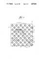
- FIG. 4is a plan view of the interconnect of the present invention.
- FIG. 5is a cross-sectional view of an interconnect according to the present invention illustrating a x--x wire bond along lines 5--5 of FIG. 4.
- FIG. 6is a cross-sectional view of an interconnect according to the present invention illustrating an y--y wire bond along lines 6--6 of FIG. 4.
- FIG. 7is a cross-sectional view of an interconnect according to the present invention illustrating an x-y wire bond along lines 7--7 of FIG. 4.
- FIG. 8is a cross-sectional view of an interconnect according to the present invention illustrating the disconnection of an x-wire along lines 8--8 of FIG. 4.
- FIG. 9is a schematic view of an x-y wire diagram.
- FIG. 9Ais an enlarged sectional view of the area 9A of the diagram of FIG. 9.
- FIGS. 10-13are cross-sectional views illustrating means for joining wires according to the present invention.
- FIG. 14is an exploded isometric bottom view of an interconnect structure according to the present invention.
- FIG. 15is a plan view of another embodiment of an interconnect according to the present invention.
- FIGS. 16-18are cross-sectional views illustrating means for joining overlapping wires in the embodiment of FIG. 15.
- FIG. 1illustrates an early design of an electrical apparatus 10.
- the wiringis shown in the form of a series of x- and y-wires 12 and 14, respectively.
- the x-wiresare positioned in the substrate 16 in a plane below the y-wires.
- the wiresare joined at select areas of overlap 17 by bumps formed in the wires.
- the x-wiresare raised and the y-wires are lowered into contact with one another.
- the overlap areas 17have an opening 18 which provides access to the wires to be joined.
- the apparatus of FIG. 1does not include ground planes and is not concerned with controlling impedance. This is because the invention addresses the need for assembly of radio sets by a universal wiring pattern scheme for detection of signals of low to moderate frequency. Signal frequencies are not addressed in this patent; the concern is with arrangement and connection of the various components of a circuit. In the era that the cited invention was conceived (1930's), the applications involved the processing of signals with frequencies equal to or less than about 10 MHz (AM radio through international short wave band). These frequencies require the circuit to conduct a signal with a risetime as short as 30 nanoseconds.
- the rate of change of a signal(as characterized by its risetime) is such that the signal does not change appreciably in time as it progresses through the circuit, i.e., the propagation time through the circuit is significantly shorter than the rise time of the signal, a controlled impedance environment in the circuitry is not required.
- the dimensions of the "radio set" circuitryare of the order of one foot, the associated circuitry propagation times would be of the order of 2-3 nanoseconds, considerably shorter than the risetime of the signal being propagated.
- the cited patentis suitable for that application, but not for the application conceived by the present invention where sub-nanosecond rise times are the rule, but the overall dimensions of the circuit are still about the same (one foot).
- the present inventionaddresses the application regime where the signal risetime is now shorter than its propagation time.
- FIG. 2is a recently designed structure which provides vias through the substrate. More specifically, FIG. 2 describes the invention of a 100 ohm controlled impedance multilayer printed circuit board.
- the boardconsists of six planar layers of conductor, each separated by dielectric. Proceeding through the structure, the top or component side 20 contains upper external signal traces 22 followed by internal upper signal traces 24, ground plane 26, power plane 28, internal lower signal traces 30 and the lower external signal traces 32 which are located on the lower "solder" side 34.
- the regular array of plated-through holes or vias 36is provided in order to make connection from any of the signal planes to the top layer, ground plane, or voltage plane as appropriate.
- the via connectionsare determined in the design of the board and accomplished in the fabrication process by a plating technique.
- the geometry of the signal trace width, thickness, and separation from the ground and power planesare so chosen to create a microstrip environment with the desired 100 ohm characteristic impedance.
- the signal trace dimensionsIn order to achieve identical impedances, the signal trace dimensions must vary according to their placement within the structure due to the surrounding electric field environment.
- FIG. 2does not provide for discretionary alteration of the finished structure by the ultimate user for a particular application.
- the via connectionsmust be accomplished during the fabrication of the circuit board. There is no provision for arbitrary circuit race interruption or arbitrary connection to another circuit race by the user as described by the present invention.
- the interconnect 40includes, from bottom to top, a first ground plane 42. Immediately above the ground plane is a dielectric material 44. Embedded within the dielectric is an orthogonal matrix of x- and y-transmission wires 46 and 48, respectively. These transmission wires, after they are interconnected, form the wiring structure which electrically connects the various electrical devices to be attached to the interconnect. A second ground plane 50 is placed on top of the interconnect structure.
- interconnect designAs previously discussed, it is the goal of much present-day interconnect design to construct an interconnect which can be mass-produced in a non-customized manner and, subsequently, interconnected or "customized" to a user-specific need.
- the objectis to move away from the construction of customized interconnects which require the laying down of wiring in a certain order and with certain specified connections.
- the present designlays down the wires in a grid. Once the interconnect is constructed, the end-user can specify the particular wiring scheme he or she needs and the wires are then connected or disconnected as necessary. The latter step is referred to as the customization step.
- the interconnect of FIG. 3has a number of vias 52 which provide access to the wires.
- vias 52To connect wires, a wire trace or other structure to be described in more detail below is extended between the vias of the selected wires.
- the wireTo disconnect a wire, the wire is chemically, electrochemically or mechanically cut at the select via.
- the via locationis of particular importance in the present invention due to the need for controlled impedance.
- the presence of a viaimplies a disruption of the ground plane. This disruption will affect the constancy of the impedance value along a circuit trace as it passes in the vicinity of a via.
- a balance of requirements(dependent upon the application) must be maintained between accessibility, in the form of the number and size of vias, and the need for an ideal transmission line environment for the conducted signals.
- the vias of the present interconnectare positioned in a geometrically controlled manner. Furthermore, the size of the vias are controlled so that they are large enough to be workable, yet small enough to avoid loss of control of the characteristic impedance. Because the via geometry is controlled, all of the conductors are equally spaced from like ground planes.
- the end-userhas an additional option in controlling impedance by closing unused via openings by foil overlayment to maintain a more ideal microstrip environment for critical applications.
- the vias according to this embodimentare shown to have a lip 54.
- the lip or offsetdecreases the likelihood that the naked wire of the connector extending from the via will contact the conductive ground plane 50.
- FIG. 4shows the interconnect 40 from above.
- the vias 52are arranged in a face-centered configuration. The figure illustrates many of the structures discussed above.
- the lip 54 of the viais shown.
- three wire traces 56are shown.
- the traces 56extend between wires to be connected. As shown, the connection can be between x-wires, between y-wires, or between an x- and a y-wire.
- the wire traceincludes the wire lead itself 58 and an insulative material 60.
- the insulation 60extends between the vias along the majority of the trace's length. The insulation is positioned between the ground plane and the trace to prevent shorting.
- FIG. 4also illustrates a cut or disconnected wire 62.
- the series of connections and disconnectionsresults in the customization of the interconnect.
- the customization, both connection and disconnection,can be performed in any number of ways.
- FIGS. 5-7 and 10-13show some examples.
- FIGS. 5-7illustrate one means for attaching wires of the interconnect, i.e., a wire trace.
- the trace 56extends between two x-wires 64 (see lines 5--5 of FIG. 4).
- the trace 56is formed by the lead 58 and an insulation layer 60.
- the insulationextends into the two vias 52 and isolates the lead 58 from the ground plane 50.
- the dielectric 44Also illustrated in FIG. 5 is the dielectric 44.
- the y-wire 70is shown in horizontal broken lines.
- the tracecan be enclosed in insulation, except for its attachment ends. Such a design avoids any problems which may arise with the trace of FIG. 5 caused by incorrect alignment of the trace.
- FIG. 5also illustrates that the trace could extend from the other direction, i.e., down and over the lower ground plane, due to the symmetry of the interconnect geometry.
- the alternative traceis shown by broken lines 68.
- FIG. 6illustrates the attachment of y-wires 70 (see lines 6--6 of FIG. 4) in a manner identical to FIG. 5.
- Like structureis labelled with like reference numbers.
- FIG. 7depicts a wire trace for attaching the transmission wires of the non-committed interconnect.
- a connectionis made between x-wire 64 and y-wire 70.
- the x-y connectionis shown along lines 7--7 of FIG. 4.
- Another method for performing the interconnectioninvolves the use of an insulated wire, as previously mentioned. Analogous to wire-wrap techniques, the insulation is removed from the ends of the insulated wire jumper and the ends are inserted between via sidewall and substrate conductor and held by friction. Alternatively, a small amount of conductive epoxy or an amalgam can be used to enhance the contact.
- Yet another methodcombines the use of the via sidewall and the conductive plane.
- the structurescan be activated by selective laser radiation to form conductive paths in a subsequent post-processing step.
- the wire trace or insulated wire jumpercan be formed from a variety of conductive materials having reasonable electrical conductivity. Suggested materials for the wire lead are copper, silver, gold and aluminum. Particularly preferred is copper.
- the insulation materialcan also be selected from a variety of materials. Examples of such materials are organic polymers, for example, polytetrafluoroethylene, polyethylene, polyimide and polyvinyl chloride. Also, ceramics and silicon are suggested non-flexible materials. Polyimide is a preferred choice.
- the form of the insulated jumpercould have the circular cross-section of an insulated wire or, alternatively, a rectangular metal trace supported on an insulating tape.
- Other cross-sectionsare envisioned, with the above simply being by way of example.
- FIG. 8illustrates the removal of a wire section of x-wire 64.
- the removalcan be accomplished by a variety of means, mechanical, electrochemical and chemical, such as, mechanically cutting or punching, cutting with a laser beam or chemical treatment.
- the most straight-forward approach to this operationis mechanical.
- a punchthe operation of which can be under software control, can remove conductor at the x- or y-conductor access vias where interruption is needed.
- An analogous chemical approachcan utilize a dispensing nozzle or pipet, positioned as in the punch example, which places a controlled amount of etchant on the conductors at the desired location. After the interruption is complete a neutralizer or water is dispensed in the same fashion to remove excess etchant and spent material.
- a third techniqueuses a laser machining process.
- a personalized maskexposing only the vias containing conductors to be interrupted, is used with a continuous raster scanned beam.
- a controlled rastered or vectored beam driven by softwarecan be utilized to address the specific via locations.
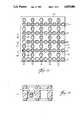
- FIG. 9summarizes the geometry or configuration of the x- and y-conductor interruptions and interconnections.
- the figureshows an illustration of connections to all I/O of an 18*18 (324 pad) 50 mil center area array package.
- FIG. 9Aschematically shows a wire trace interconnection between an x-and y-wire. In order to avoid complexity in the schematic, FIG. 9 shows every fifth via since these are the points for external connections.
- the wire tracecan be physically attached to the transmission wire, or conductor, by a variety of methods.
- FIG. 10shows the use of a mechanical connector.
- the connector 72is in an H or double-U configuration.
- the top-Ureceives the end of the wire trace 56 or insulated wire jumper.
- the lower-Uengages and receives the transmission line 64.
- the U-shaped areasshould be dimensioned to provide interference fits with the trace and conductor.
- the connector 72can be formed from a variety of materials, particularly, springy material with a large elastic behavior region. Alloys such as phosphor-bronze and beryllium-copper are suggested. Alternatively, shape memory alloys can be used. These materials change dimension on traversing a temperature transition and return to a predetermined shape.
- FIG. 11illustrates a solder connection 74 between trace 56 and wire 64.
- the connection of FIG. 5can also be a solder connection.
- a conductive epoxycan be used to make the conductive connection between trace and conductor.
- the via sidewalls 78serve as dams to control placement of the epoxy or solder.
- Suggested epoxiesinclude thermally activated and silver loaded room temperature setting materials.
- Suggested soldersinclude various lead-tin and indium based materials, as well as other metal alloy systems such as amalgams. Particularly preferred are conductive epoxies and low temperature solders commonly employed by the hybrid circuits industry.
- FIG. 12shows yet another means for attaching the trace 56 to wire 74.
- Thisis referred to as single point bonding.
- a stationary anvil 80projects into the selected via 52 from the backside of the substrate and supports the conductor 74 to be interconnected.
- the thermode or ultrasonic-coupled bond tool 82(depending on whether thermocompression or thermosonic methods are used) position the connector, e.g., wire trace or insulated bonding wire, through the via on the front side of the interconnect to effect a bond. The same procedure is used on the opposing end of the interconnect wire.
- Another method, shown in FIG. 13, for interconnecting the conductorsis to fill the vias with a conductive material 84 to which the trace 56 can be bonded.
- the viacan be filled, for example, by sputtering, evaporation, or ion beam deposition.
- the filled viaprovides for bottom and top trace or wire attachment.
- the interconnectcan be manufactured by producing symmetric wafers of ground plane 86--dielectric 88--conductor 90. The wafers are arranged so that the conductors are turned orthogonal to each other, as shown. A dielectric 92 is then positioned between the two wafers so as to align the vias. Though not shown, the dielectric 92 can have channels to accommodate the conductors 90.
- the interconnectcan be fabricated by a variety of known processes according to the feature size of the via and microstrip traces.
- a 50 mil gridis the requirement for a discretionary wiring scheme (implying 20 mil diameter vias and 10 mil wide traces with a dielectric thickness between each conductor layer of 5 mils if the design is scaled)
- an epoxy glass circuit board processing techniquecould be employed.
- the required via grid dimensionmight be 5 mils (or less) and the medium film substrate process on silicon can be employed.
- a flexible substrate fabrication processmay be employed.
- An example of the latteris a fabrication process utilizing plating of photodefined metal layers and alternate coating of photodefined polymer layers starting with either a metal foil or polymer film.
- An alternative approach to the flexible substrate constructionis to employ punched metal films and laminated dielectrics in an alternate layered construction.
- the present inventionis scaleable depending upon application.
- the fabrication processdepends, accordingly, on the application of the substrate.
- Via profilescan be made, for example, by etching polyimide with a CO 2 laser using the previously etched via pattern in the conductor plane as a mask. CO 2 radiation is absorbed by polyimide, reflected from copper.
- the above production methodis useful, for example, in the smaller scale, substrate technology.
- the H-shaped and U-shaped connectors discussed abovemay not be practical as a technique for joining the wire traces or jumpers to the underlying conductors.
- an advantage of the present inventionis that it is scaleable.
- the envisioned scaledepends on the application.
- the inventionis applicable in the TAB (tape automated bonding) tape or flexible circuit process using a polyimide/copper or similar multilayer composite construction.
- Appropriate dimensionsare 2 mil circuit trace widths and 0.7 mil thickness (NEMA 1/2 ounce copper), 4 mil via diameters, and 10 mil face centered via arrays as described in FIG. 4.
- layer thickness of 1 mil between trace and ground planeis appropriate; this configuration would yield a characteristic impedance of about 50 ohms.
- the DIPis interconnected to the substrate by the via filling attachment means or by the designing of a mechanical contact or clip to attach to the individual package leads.
- mechanical means of programming the interconnectssuch as mechanically punching out the undesired connections and pressure contact to the desired connections via devices such as 72 are feasible.
- the trace widthscould be 1 mils or thinner and of 1/4 ounce copper or less. Trace spacing is 5 mils or less with a via diameter of 2 mils and the dielectric thickness scales to 1/2 mil for a 50 ohm impedance.
- One means of accomplishing thiswould be to attach a wire (gold or aluminum) to the desired connection in the appropriate via by means of the epoxy, solder, or amalgam techniques outlined for the flexcircuit case, or by means of laser welding or soldering. This step is accomplished prior to or after bonding the other end of the wire to the connection pads of the chip.
- Another exampleinvolves the use of more complex chips which have previously had a TAB tape interconnect attached.
- the outer lead bond sitesare attached to selected substrate via connection sites by the described method above. It is desirable to design the outer lead bond sites of the tape to connect directly with the grid pattern (or integral multiple thereof) for optimum connection capability. For example, if the medium film substrate is in the form of 5 mil face centered layout, the TAB tape outer lead bond sites should be on 5 or 10 mil centers for optimum utilization of the routing capability of the substrate.
- FIG. 15Another embodiment of the present interconnect structure is shown in FIG. 15.
- the vias providing access to the x- and y-wiresindividually 94 and 96 respectively, there are provided vias 98 in the areas of x-y overlap. Accordingly, there are fifty percent more vias per unit substrate surface area compared to the embodiment of FIG. 4.
- the x-y interconnectionsusing the methods outlined in the preceding paragraphs, are made within these additional vias. With this arrangement, one possibility is to make x-y connections only at these additional vias 98.
- the x- and y-vias 94 and 96can be used solely for conductor interruption. Accordingly, while the figure shows a lip 100 in the vias, the edges of the conductive plane may be flush with the via edges, since no interconnects are made over the conductive plane surface.
- the required hole sizemay force substrate configurations to be fabricated with x- and y-arrays on 12 mils or greater centers, for the same trace width and dielectric thickness, thus causing a reduction in interconnect density.
- the shielding effect provided by the outer conductive planesis omitted where it is most necessary to reduce interaction between the orthogonal arrays--in the vicinity of the x-y crossovers.
- the interaction between x- and y-wires in unused vias 98can be substantially reduced by restoration of the outer conductive plane. This may be done by closing unused via openings by foil overlayment to maintain a more ideal microstrip environment.
- FIGS. 16-18illustrate various means for interconnecting the x- and y-wires at vias 98.
- FIG. 16illustrates a mechanical clip 102 which frictionally engages x-wire 104 and y-wire 106. As can be seen by reference to FIG. 15, the clip is placed diagonally across the x-wire.
- FIGS. 16A-Care cross-sectional views of the clip along various axes to more specifically illustrate the clip structure.
- FIG. 16illustrates the use of mechanical devices, similar to those used in insulation displacement connectors which are believed to involve the formation of gas-tight microwelds between the sliding interface surfaces, as the connection is made, due to the high pressures generated by the elastic deformation of the device.
- This use of a mechanically generated connectionis only appropriate at the largest scale of the invention, for vias and traces of at least 10 and 20 mils size, respectively, in order for the interconnection device to be of reasonable size and durability.
- FIG. 17depicts a via filling technique.
- This techniquecan be used at any scale but is most appropriate for the smaller feature sizes (via size 10 mils or less).
- This processis analogous to plating-up or electroforming but is more conveniently accomplished by the end user by filling with an amalgam, epoxy or solder particle-in-flux solution (as in hybrid circuit technology) which can be dispensed manually (or in an automated process) from a pipet and subsequently cured (or reflowed).
- the curing or reflow stepcan be accomplished by heating the entire substrate or by the selective heating by an appropriate radiation source such as by a laser beam of the proper wavelength for energy absorption by the via fill material.
- FIG. 18depicts a direct x- to y-bond 110.
- a bond between individual members of the x-y arraycan be accomplished as described immediately above.
- a wide variety of materials and technologycan be utilized to construct the discretionary interconnect of the present invention.
- a preferred technologyis the copper/polyimide technology, such as used in the manufacture of beam lead tape or flexible circuitry.
- the individual conductorsare of about 1/2 ounce copper, about 2 mils in width, on about 10 mils centers, and spaced about 1 mils from the nearer conducting plane.
- the orthogonal conductor arraysare separated by about 1 to 3 mils of dielectric.
- the individual x- and y- conductorspossess approximately 50 ohm characteristic impedance, with respect to outer conducting planes.
- the viasare formed on a faced-centered interdigited arrangement of about 10 mil center square arrays of about 6 mil diameter vias.
Landscapes
- Engineering & Computer Science (AREA)
- Microelectronics & Electronic Packaging (AREA)
- Manufacturing & Machinery (AREA)
- Printing Elements For Providing Electric Connections Between Printed Circuits (AREA)
Abstract
Description
Claims (12)
Priority Applications (1)
| Application Number | Priority Date | Filing Date | Title |
|---|---|---|---|
| US07/194,666US4859806A (en) | 1988-05-17 | 1988-05-17 | Discretionary interconnect |
Applications Claiming Priority (1)
| Application Number | Priority Date | Filing Date | Title |
|---|---|---|---|
| US07/194,666US4859806A (en) | 1988-05-17 | 1988-05-17 | Discretionary interconnect |
Publications (1)
| Publication Number | Publication Date |
|---|---|
| US4859806Atrue US4859806A (en) | 1989-08-22 |
Family
ID=22718451
Family Applications (1)
| Application Number | Title | Priority Date | Filing Date |
|---|---|---|---|
| US07/194,666Expired - LifetimeUS4859806A (en) | 1988-05-17 | 1988-05-17 | Discretionary interconnect |
Country Status (1)
| Country | Link |
|---|---|
| US (1) | US4859806A (en) |
Cited By (71)
| Publication number | Priority date | Publication date | Assignee | Title |
|---|---|---|---|---|
| WO1990010370A1 (en)* | 1989-02-27 | 1990-09-07 | Fmtt, Inc. | Matrix capacitor |
| US5013249A (en)* | 1986-06-19 | 1991-05-07 | Labinal Components And Systems, Inc. | Electrical connectors |
| US5038252A (en)* | 1989-01-26 | 1991-08-06 | Teradyne, Inc. | Printed circuit boards with improved electrical current control |
| US5040996A (en)* | 1987-12-31 | 1991-08-20 | Franz Kirsten Elektrotechnische Spezialfabrik | Central circuit arrangement for motor vehicles |
| US5102352A (en)* | 1990-01-18 | 1992-04-07 | Kel Corporation | High frequency electrical connector comprising multilayer circuit board |
| US5133669A (en)* | 1990-07-23 | 1992-07-28 | Northern Telecom Limited | Circuit board pins |
| US5187431A (en)* | 1990-06-19 | 1993-02-16 | Sgs-Thomson Microelectronics S.R.L. | Universal multicontact connection between an ews probe card and a test card of a "test-on-wafer" station |
| US5213521A (en)* | 1991-01-22 | 1993-05-25 | Kel Corporation | High frequency electrical connector assembly |
| US5270491A (en)* | 1990-10-09 | 1993-12-14 | Eastman Kodak Company | Hermetically sealed microelectronic package |
| WO1994003036A1 (en)* | 1992-07-24 | 1994-02-03 | Tessera, Inc. | Semiconductor connection components and methods with releasable lead support |
| US5285018A (en)* | 1992-10-02 | 1994-02-08 | International Business Machines Corporation | Power and signal distribution in electronic packaging |
| US5491302A (en)* | 1994-09-19 | 1996-02-13 | Tessera, Inc. | Microelectronic bonding with lead motion |
| US5496971A (en)* | 1993-09-29 | 1996-03-05 | Fujitsu Limited | Circuit arrangement for multilayer printed circuit board |
| US5508938A (en)* | 1992-08-13 | 1996-04-16 | Fujitsu Limited | Special interconnect layer employing offset trace layout for advanced multi-chip module packages |
| US5518426A (en)* | 1994-03-07 | 1996-05-21 | Burndy Corporation | Electrical connector and method of assembling an electrical connector with rows of interspaced contacts |
| US5597313A (en)* | 1986-06-19 | 1997-01-28 | Labinal Components And Systems, Inc. | Electrical connectors |
| US5600100A (en)* | 1991-11-15 | 1997-02-04 | Itt Automotive Europe Gmbh | Electrical device, in particular steering column switch for automotive vehicles |
| US5612511A (en)* | 1995-09-25 | 1997-03-18 | Hewlett-Packard Company | Double-sided electrical interconnect flexible circuit for ink-jet hard copy systems |
| US5637834A (en)* | 1995-02-03 | 1997-06-10 | Motorola, Inc. | Multilayer circuit substrate and method for forming same |
| US5638598A (en)* | 1993-06-17 | 1997-06-17 | Hitachi Chemical Company, Ltd. | Process for producing a printed wiring board |
| US5672062A (en)* | 1991-01-30 | 1997-09-30 | Labinal Components And Systems, Inc. | Electrical connectors |
| FR2749982A1 (en)* | 1996-06-17 | 1997-12-19 | Le Port Joel | DEVICE FOR MAKING ELECTRIC WIRING CONNECTIONS |
| US5723823A (en)* | 1994-06-09 | 1998-03-03 | Dell Usa, L.P. | Circuit board with enhanced rework configuration |
| US5727231A (en)* | 1994-07-15 | 1998-03-10 | International Business Machines Corporation | Method for personalizing integrated circuit devices |
| WO1998025301A1 (en)* | 1996-12-02 | 1998-06-11 | Minnesota Mining And Manufacturing Company | Tab tape ball grid array package with vias laterally offset from solder ball bond sites |
| US5886309A (en)* | 1995-11-02 | 1999-03-23 | Fujitsu Limited | Matrix switch board, connection pin, and method of fabricating them |
| US5937276A (en)* | 1996-12-13 | 1999-08-10 | Tessera, Inc. | Bonding lead structure with enhanced encapsulation |
| US5977618A (en)* | 1992-07-24 | 1999-11-02 | Tessera, Inc. | Semiconductor connection components and methods with releasable lead support |
| US6054756A (en)* | 1992-07-24 | 2000-04-25 | Tessera, Inc. | Connection components with frangible leads and bus |
| US6081035A (en)* | 1996-10-24 | 2000-06-27 | Tessera, Inc. | Microelectronic bond ribbon design |
| US6081999A (en)* | 1994-01-25 | 2000-07-04 | Yazaki Corporation | Wire-circuit sheet manufacturing method |
| US6093933A (en)* | 1998-03-16 | 2000-07-25 | Micron Technology, Inc. | Method and apparatus for fabricating electronic device |
| US6143990A (en)* | 1996-06-25 | 2000-11-07 | Fuji Xerox Co., Ltd. | Printed wiring board with two ground planes connected by resistor |
| US6181219B1 (en) | 1998-12-02 | 2001-01-30 | Teradyne, Inc. | Printed circuit board and method for fabricating such board |
| US6184477B1 (en)* | 1998-12-02 | 2001-02-06 | Kyocera Corporation | Multi-layer circuit substrate having orthogonal grid ground and power planes |
| US6255600B1 (en) | 1993-03-01 | 2001-07-03 | The Board Of Trustees Of The University Of Arkansas | Electronic interconnection medium having offset electrical mesh plane |
| US20010008313A1 (en)* | 1999-09-02 | 2001-07-19 | Intel Corporation | Chip package with degassing holes |
| US6303871B1 (en)* | 1999-06-11 | 2001-10-16 | Intel Corporation | Degassing hole design for olga trace impedance |
| US6329607B1 (en) | 1995-09-18 | 2001-12-11 | Tessera, Inc. | Microelectronic lead structures with dielectric layers |
| US6386887B2 (en)* | 2000-03-14 | 2002-05-14 | Framatome Connectors International | Connector provided with configurable contacts |
| US6415504B1 (en)* | 1996-02-28 | 2002-07-09 | Fujitsu Limited | Altering method of circuit pattern of printed-circuit board |
| US6443737B2 (en)* | 2000-01-19 | 2002-09-03 | Sumitomo Wiring Systems, Ltd. | Circuit board, electrical connection box having the circuit board and method of making the circuit board |
| US20020151111A1 (en)* | 1995-05-08 | 2002-10-17 | Tessera, Inc. | P-connection components with frangible leads and bus |
| US6528757B2 (en)* | 2000-06-02 | 2003-03-04 | Nec Corporation | Apparatus processing a gate portion in a semiconductor manufacturing apparatus, which remove a gate correspondence portion from a semiconductor package connected to a lead frame, and a resin burr deposited on a lead portion associated with the semiconductor package |
| US6528735B1 (en)* | 2001-09-07 | 2003-03-04 | International Business Machines Corporation | Substrate design of a chip using a generic substrate design |
| US20030161121A1 (en)* | 2000-06-09 | 2003-08-28 | Olli Salmela | Trimming of embedded structures |
| US6613988B2 (en)* | 2001-08-23 | 2003-09-02 | Dirk Powers | Circuit board system with raised interconnects of conductive circuit traces |
| US20040261263A1 (en)* | 2003-06-30 | 2004-12-30 | Stephen Nelson | Systems and methods for fabricating printed circuit boards |
| US20040264153A1 (en)* | 2003-06-24 | 2004-12-30 | Payne Jason J. | Printed circuit board for high speed, high density electrical connector with improved cross-talk minimization, attenuation and impedance mismatch characteristics |
| US20050241852A1 (en)* | 2004-05-03 | 2005-11-03 | Labinal | Cross-connecting by permutations using configurable printed circuits |
| US7638715B2 (en)* | 2005-07-22 | 2009-12-29 | Fujitsu Component Limited | Printed circuit board and manufacturing method therefor |
| US20100084178A1 (en)* | 2008-10-08 | 2010-04-08 | Sun Microsystems, Inc. | bond strength and interconnection in a via |
| US20100277882A1 (en)* | 2009-04-29 | 2010-11-04 | Hong Fu Jin Precision Industry (Shenzhen) Co., Ltd. | Motherboard and motherboard layout method |
| US7999192B2 (en) | 2007-03-14 | 2011-08-16 | Amphenol Corporation | Adjacent plated through holes with staggered couplings for crosstalk reduction in high speed printed circuit boards |
| US20170170592A1 (en)* | 2011-06-06 | 2017-06-15 | Nuvotronics, Inc. | Batch fabricated microconnectors |
| US20170219746A1 (en)* | 2014-08-29 | 2017-08-03 | National Institute For Materials Science | Electromagnetic Wave Absorbing/Radiating Material, Method of Manufacturing Same, and Infrared Source |
| US9888600B2 (en) | 2013-03-15 | 2018-02-06 | Nuvotronics, Inc | Substrate-free interconnected electronic mechanical structural systems |
| US9993982B2 (en) | 2011-07-13 | 2018-06-12 | Nuvotronics, Inc. | Methods of fabricating electronic and mechanical structures |
| US10002818B2 (en) | 2007-03-20 | 2018-06-19 | Nuvotronics, Inc. | Integrated electronic components and methods of formation thereof |
| US10074885B2 (en) | 2003-03-04 | 2018-09-11 | Nuvotronics, Inc | Coaxial waveguide microstructures having conductors formed by plural conductive layers |
| US10076042B2 (en) | 2011-06-05 | 2018-09-11 | Nuvotronics, Inc | Devices and methods for solder flow control in three-dimensional microstructures |
| US10135109B2 (en) | 2007-03-20 | 2018-11-20 | Nuvotronics, Inc | Method of forming a coaxial line microstructure having an enlarged region on a substrate and removing the coaxial line microstructure from the substrate for mounting on a mounting substrate |
| US10193203B2 (en) | 2013-03-15 | 2019-01-29 | Nuvotronics, Inc | Structures and methods for interconnects and associated alignment and assembly mechanisms for and between chips, components, and 3D systems |
| US10310009B2 (en) | 2014-01-17 | 2019-06-04 | Nuvotronics, Inc | Wafer scale test interface unit and contactors |
| US10319654B1 (en) | 2017-12-01 | 2019-06-11 | Cubic Corporation | Integrated chip scale packages |
| US10497511B2 (en) | 2009-11-23 | 2019-12-03 | Cubic Corporation | Multilayer build processes and devices thereof |
| US10511073B2 (en) | 2014-12-03 | 2019-12-17 | Cubic Corporation | Systems and methods for manufacturing stacked circuits and transmission lines |
| US10847469B2 (en) | 2016-04-26 | 2020-11-24 | Cubic Corporation | CTE compensation for wafer-level and chip-scale packages and assemblies |
| US20210057835A1 (en)* | 2019-08-20 | 2021-02-25 | Seagate Technology Llc | Electrical connector with flexible circuit and stiffener |
| US20220369468A1 (en)* | 2014-11-06 | 2022-11-17 | Semiconductor Components Industries, Llc | Substrate structures and methods of manufacture |
| US20240057253A1 (en)* | 2020-12-16 | 2024-02-15 | Lg Innotek Co., Ltd. | Circuit board |
Citations (35)
| Publication number | Priority date | Publication date | Assignee | Title |
|---|---|---|---|---|
| US2019625A (en)* | 1934-03-30 | 1935-11-05 | Rca Corp | Electrical apparatus |
| US2914706A (en)* | 1956-03-05 | 1959-11-24 | Librascope Inc | General purpose connector card |
| US3128332A (en)* | 1960-03-30 | 1964-04-07 | Hughes Aircraft Co | Electrical interconnection grid and method of making same |
| US3137534A (en)* | 1961-10-12 | 1964-06-16 | William J Schafer | Pre-wired criss-cross control panel |
| US3142112A (en)* | 1960-03-30 | 1964-07-28 | Hughes Aircraft Co | Method of making an electrical interconnection grid |
| US3148438A (en)* | 1959-05-25 | 1964-09-15 | Vero Prec Engineering Ltd | Method of making wiring boards |
| US3177405A (en)* | 1959-12-23 | 1965-04-06 | Sippican Corp | Modular electrical assembly |
| US3189978A (en)* | 1962-04-27 | 1965-06-22 | Rca Corp | Method of making multilayer circuits |
| US3312871A (en)* | 1964-12-23 | 1967-04-04 | Ibm | Interconnection arrangement for integrated circuits |
| US3478425A (en)* | 1966-01-31 | 1969-11-18 | Int Standard Electric Corp | Method of making an electrical assembly |
| US3485934A (en)* | 1968-10-31 | 1969-12-23 | Xerox Corp | Circuit board |
| US3535780A (en)* | 1967-10-04 | 1970-10-27 | Ralph Berger | Continuous process for the production of electrical circuits |
| US3564115A (en)* | 1967-12-08 | 1971-02-16 | Ferranti Ltd | Electrical interconnection grids |
| US3573708A (en)* | 1969-07-22 | 1971-04-06 | Ite Imperial Corp | Tap block assembly |
| GB1233844A (en)* | 1969-05-05 | 1971-06-03 | ||
| US3621116A (en)* | 1969-12-29 | 1971-11-16 | Bertram C Adams | Printed circuit board |
| US3702025A (en)* | 1969-05-12 | 1972-11-07 | Honeywell Inc | Discretionary interconnection process |
| US3711627A (en)* | 1969-12-12 | 1973-01-16 | K Maringulov | Device for electrical connection of electric and electronic components and method of its manufacture |
| US3718936A (en)* | 1971-06-16 | 1973-02-27 | American Express Invest | Electrostatic matrix head construction |
| DE2234033A1 (en)* | 1972-07-11 | 1974-01-31 | Peter Kammermeier | BASE PLATE FOR SOLDERLESS CONSTRUCTION OF ELECTRONIC CIRCUITS |
| US3824433A (en)* | 1973-03-05 | 1974-07-16 | Thunderco Inc | Universal circuit board |
| US3838317A (en)* | 1973-07-12 | 1974-09-24 | Bell Telephone Labor Inc | Cross connect switch |
| US4064357A (en)* | 1975-12-02 | 1977-12-20 | Teledyne Electro-Mechanisms | Interconnected printed circuits and method of connecting them |
| US4254445A (en)* | 1979-05-07 | 1981-03-03 | International Business Machines Corporation | Discretionary fly wire chip interconnection |
| US4434321A (en)* | 1981-02-09 | 1984-02-28 | International Computers Limited | Multilayer printed circuit boards |
| US4458297A (en)* | 1981-01-16 | 1984-07-03 | Mosaic Systems, Inc. | Universal interconnection substrate |
| US4467400A (en)* | 1981-01-16 | 1984-08-21 | Burroughs Corporation | Wafer scale integrated circuit |
| US4486705A (en)* | 1981-01-16 | 1984-12-04 | Burroughs Corporation | Method of testing networks on a wafer having grounding points on its periphery |
| US4521262A (en)* | 1983-01-10 | 1985-06-04 | Pellegrino Peter P | Method for mass producing printed circuit boards |
| US4524239A (en)* | 1981-09-02 | 1985-06-18 | Francois Rouge | Multi-layer electric circuit board and blanks therefor |
| US4560962A (en)* | 1983-08-30 | 1985-12-24 | Burroughs Corporation | Multilayered printed circuit board with controlled 100 ohm impedance |
| US4636919A (en)* | 1985-03-20 | 1987-01-13 | Hitachi, Ltd. | Multilayer printed circuit board |
| US4679321A (en)* | 1985-10-18 | 1987-07-14 | Kollmorgen Technologies Corporation | Method for making coaxial interconnection boards |
| US4743710A (en)* | 1985-10-18 | 1988-05-10 | Kollmorgen Technologies Corporation | Coaxial interconnection boards |
| US4764644A (en)* | 1985-09-30 | 1988-08-16 | Microelectronics Center Of North Carolina | Microelectronics apparatus |
- 1988
- 1988-05-17USUS07/194,666patent/US4859806A/ennot_activeExpired - Lifetime
Patent Citations (35)
| Publication number | Priority date | Publication date | Assignee | Title |
|---|---|---|---|---|
| US2019625A (en)* | 1934-03-30 | 1935-11-05 | Rca Corp | Electrical apparatus |
| US2914706A (en)* | 1956-03-05 | 1959-11-24 | Librascope Inc | General purpose connector card |
| US3148438A (en)* | 1959-05-25 | 1964-09-15 | Vero Prec Engineering Ltd | Method of making wiring boards |
| US3177405A (en)* | 1959-12-23 | 1965-04-06 | Sippican Corp | Modular electrical assembly |
| US3128332A (en)* | 1960-03-30 | 1964-04-07 | Hughes Aircraft Co | Electrical interconnection grid and method of making same |
| US3142112A (en)* | 1960-03-30 | 1964-07-28 | Hughes Aircraft Co | Method of making an electrical interconnection grid |
| US3137534A (en)* | 1961-10-12 | 1964-06-16 | William J Schafer | Pre-wired criss-cross control panel |
| US3189978A (en)* | 1962-04-27 | 1965-06-22 | Rca Corp | Method of making multilayer circuits |
| US3312871A (en)* | 1964-12-23 | 1967-04-04 | Ibm | Interconnection arrangement for integrated circuits |
| US3478425A (en)* | 1966-01-31 | 1969-11-18 | Int Standard Electric Corp | Method of making an electrical assembly |
| US3535780A (en)* | 1967-10-04 | 1970-10-27 | Ralph Berger | Continuous process for the production of electrical circuits |
| US3564115A (en)* | 1967-12-08 | 1971-02-16 | Ferranti Ltd | Electrical interconnection grids |
| US3485934A (en)* | 1968-10-31 | 1969-12-23 | Xerox Corp | Circuit board |
| GB1233844A (en)* | 1969-05-05 | 1971-06-03 | ||
| US3702025A (en)* | 1969-05-12 | 1972-11-07 | Honeywell Inc | Discretionary interconnection process |
| US3573708A (en)* | 1969-07-22 | 1971-04-06 | Ite Imperial Corp | Tap block assembly |
| US3711627A (en)* | 1969-12-12 | 1973-01-16 | K Maringulov | Device for electrical connection of electric and electronic components and method of its manufacture |
| US3621116A (en)* | 1969-12-29 | 1971-11-16 | Bertram C Adams | Printed circuit board |
| US3718936A (en)* | 1971-06-16 | 1973-02-27 | American Express Invest | Electrostatic matrix head construction |
| DE2234033A1 (en)* | 1972-07-11 | 1974-01-31 | Peter Kammermeier | BASE PLATE FOR SOLDERLESS CONSTRUCTION OF ELECTRONIC CIRCUITS |
| US3824433A (en)* | 1973-03-05 | 1974-07-16 | Thunderco Inc | Universal circuit board |
| US3838317A (en)* | 1973-07-12 | 1974-09-24 | Bell Telephone Labor Inc | Cross connect switch |
| US4064357A (en)* | 1975-12-02 | 1977-12-20 | Teledyne Electro-Mechanisms | Interconnected printed circuits and method of connecting them |
| US4254445A (en)* | 1979-05-07 | 1981-03-03 | International Business Machines Corporation | Discretionary fly wire chip interconnection |
| US4458297A (en)* | 1981-01-16 | 1984-07-03 | Mosaic Systems, Inc. | Universal interconnection substrate |
| US4467400A (en)* | 1981-01-16 | 1984-08-21 | Burroughs Corporation | Wafer scale integrated circuit |
| US4486705A (en)* | 1981-01-16 | 1984-12-04 | Burroughs Corporation | Method of testing networks on a wafer having grounding points on its periphery |
| US4434321A (en)* | 1981-02-09 | 1984-02-28 | International Computers Limited | Multilayer printed circuit boards |
| US4524239A (en)* | 1981-09-02 | 1985-06-18 | Francois Rouge | Multi-layer electric circuit board and blanks therefor |
| US4521262A (en)* | 1983-01-10 | 1985-06-04 | Pellegrino Peter P | Method for mass producing printed circuit boards |
| US4560962A (en)* | 1983-08-30 | 1985-12-24 | Burroughs Corporation | Multilayered printed circuit board with controlled 100 ohm impedance |
| US4636919A (en)* | 1985-03-20 | 1987-01-13 | Hitachi, Ltd. | Multilayer printed circuit board |
| US4764644A (en)* | 1985-09-30 | 1988-08-16 | Microelectronics Center Of North Carolina | Microelectronics apparatus |
| US4679321A (en)* | 1985-10-18 | 1987-07-14 | Kollmorgen Technologies Corporation | Method for making coaxial interconnection boards |
| US4743710A (en)* | 1985-10-18 | 1988-05-10 | Kollmorgen Technologies Corporation | Coaxial interconnection boards |
Non-Patent Citations (2)
| Title |
|---|
| Anderson, P. C. et al; Josephson Package Repair; IBM Technical Disclosure Bulletin; vol. 26, No. 12; May 84; pg. 6244.* |
| Flexmark Brochure (N date).* |
Cited By (124)
| Publication number | Priority date | Publication date | Assignee | Title |
|---|---|---|---|---|
| US5597313A (en)* | 1986-06-19 | 1997-01-28 | Labinal Components And Systems, Inc. | Electrical connectors |
| US5013249A (en)* | 1986-06-19 | 1991-05-07 | Labinal Components And Systems, Inc. | Electrical connectors |
| US5040996A (en)* | 1987-12-31 | 1991-08-20 | Franz Kirsten Elektrotechnische Spezialfabrik | Central circuit arrangement for motor vehicles |
| US5038252A (en)* | 1989-01-26 | 1991-08-06 | Teradyne, Inc. | Printed circuit boards with improved electrical current control |
| WO1990010370A1 (en)* | 1989-02-27 | 1990-09-07 | Fmtt, Inc. | Matrix capacitor |
| US5102352A (en)* | 1990-01-18 | 1992-04-07 | Kel Corporation | High frequency electrical connector comprising multilayer circuit board |
| US5187431A (en)* | 1990-06-19 | 1993-02-16 | Sgs-Thomson Microelectronics S.R.L. | Universal multicontact connection between an ews probe card and a test card of a "test-on-wafer" station |
| US5133669A (en)* | 1990-07-23 | 1992-07-28 | Northern Telecom Limited | Circuit board pins |
| US5270491A (en)* | 1990-10-09 | 1993-12-14 | Eastman Kodak Company | Hermetically sealed microelectronic package |
| US5213521A (en)* | 1991-01-22 | 1993-05-25 | Kel Corporation | High frequency electrical connector assembly |
| US5704795A (en)* | 1991-01-30 | 1998-01-06 | Labinal Components And Systems, Inc. | Electrical connectors |
| US5672062A (en)* | 1991-01-30 | 1997-09-30 | Labinal Components And Systems, Inc. | Electrical connectors |
| US5600100A (en)* | 1991-11-15 | 1997-02-04 | Itt Automotive Europe Gmbh | Electrical device, in particular steering column switch for automotive vehicles |
| US5977618A (en)* | 1992-07-24 | 1999-11-02 | Tessera, Inc. | Semiconductor connection components and methods with releasable lead support |
| US6054756A (en)* | 1992-07-24 | 2000-04-25 | Tessera, Inc. | Connection components with frangible leads and bus |
| US5787581A (en)* | 1992-07-24 | 1998-08-04 | Tessera, Inc. | Methods of making semiconductor connection components with releasable load support |
| US6359236B1 (en) | 1992-07-24 | 2002-03-19 | Tessera, Inc. | Mounting component with leads having polymeric strips |
| US5536909A (en)* | 1992-07-24 | 1996-07-16 | Tessera, Inc. | Semiconductor connection components and methods with releasable lead support |
| US6272744B1 (en) | 1992-07-24 | 2001-08-14 | Tessera, Inc. | Semiconductor connection components and methods with releasable lead support |
| WO1994003036A1 (en)* | 1992-07-24 | 1994-02-03 | Tessera, Inc. | Semiconductor connection components and methods with releasable lead support |
| US5915752A (en)* | 1992-07-24 | 1999-06-29 | Tessera, Inc. | Method of making connections to a semiconductor chip assembly |
| US5489749A (en)* | 1992-07-24 | 1996-02-06 | Tessera, Inc. | Semiconductor connection components and method with releasable lead support |
| US6888229B2 (en) | 1992-07-24 | 2005-05-03 | Tessera, Inc. | Connection components with frangible leads and bus |
| US5508938A (en)* | 1992-08-13 | 1996-04-16 | Fujitsu Limited | Special interconnect layer employing offset trace layout for advanced multi-chip module packages |
| US5285018A (en)* | 1992-10-02 | 1994-02-08 | International Business Machines Corporation | Power and signal distribution in electronic packaging |
| US6388200B2 (en) | 1993-03-01 | 2002-05-14 | The Board Of Trustees Of The University Of Arkansas | Electronic interconnection medium having offset electrical mesh plane |
| US6297460B1 (en)* | 1993-03-01 | 2001-10-02 | The Board Of Trustees Of The University Of Arkansas | Multichip module and method of forming same |
| US6255600B1 (en) | 1993-03-01 | 2001-07-03 | The Board Of Trustees Of The University Of Arkansas | Electronic interconnection medium having offset electrical mesh plane |
| US5638598A (en)* | 1993-06-17 | 1997-06-17 | Hitachi Chemical Company, Ltd. | Process for producing a printed wiring board |
| US5496971A (en)* | 1993-09-29 | 1996-03-05 | Fujitsu Limited | Circuit arrangement for multilayer printed circuit board |
| US6137054A (en)* | 1994-01-25 | 2000-10-24 | Yazaki Corporation | Wire-circuit sheet and electric junction box thereof |
| US6081999A (en)* | 1994-01-25 | 2000-07-04 | Yazaki Corporation | Wire-circuit sheet manufacturing method |
| US5518426A (en)* | 1994-03-07 | 1996-05-21 | Burndy Corporation | Electrical connector and method of assembling an electrical connector with rows of interspaced contacts |
| US5723823A (en)* | 1994-06-09 | 1998-03-03 | Dell Usa, L.P. | Circuit board with enhanced rework configuration |
| US5806178A (en)* | 1994-06-09 | 1998-09-15 | Dell U.S.A., L.P. | Circuit board with enhanced rework configuration |
| US5727231A (en)* | 1994-07-15 | 1998-03-10 | International Business Machines Corporation | Method for personalizing integrated circuit devices |
| US5491302A (en)* | 1994-09-19 | 1996-02-13 | Tessera, Inc. | Microelectronic bonding with lead motion |
| WO1996009745A1 (en)* | 1994-09-19 | 1996-03-28 | Tessera, Inc. | Microelectronic bonding with lead motion |
| US5637834A (en)* | 1995-02-03 | 1997-06-10 | Motorola, Inc. | Multilayer circuit substrate and method for forming same |
| US20020151111A1 (en)* | 1995-05-08 | 2002-10-17 | Tessera, Inc. | P-connection components with frangible leads and bus |
| US5844168A (en)* | 1995-08-01 | 1998-12-01 | Minnesota Mining And Manufacturing Company | Multi-layer interconnect sutructure for ball grid arrays |
| US6329607B1 (en) | 1995-09-18 | 2001-12-11 | Tessera, Inc. | Microelectronic lead structures with dielectric layers |
| US5612511A (en)* | 1995-09-25 | 1997-03-18 | Hewlett-Packard Company | Double-sided electrical interconnect flexible circuit for ink-jet hard copy systems |
| US5937494A (en)* | 1995-09-25 | 1999-08-17 | Hewlett-Packard Company | Method for assembling an ink-jet pen having a double-sided electrical interconnect flexible circuit |
| US6116912A (en)* | 1995-11-02 | 2000-09-12 | Fujitsu Limited | Matrix switch board used to connect/disconnect switching system-and subscriber-side line |
| US6216342B1 (en) | 1995-11-02 | 2001-04-17 | Fujitsu Limited | Method for fabricating a matrix switchboard and connection pin |
| US5886309A (en)* | 1995-11-02 | 1999-03-23 | Fujitsu Limited | Matrix switch board, connection pin, and method of fabricating them |
| US20020138979A1 (en)* | 1996-02-28 | 2002-10-03 | Fujitsu Limited | Altering method of circuit pattern of printed-circuit board, cutting method of circuit pattern of printed-circuit board and printed-circuit board having altered circuit pattern |
| US6909065B2 (en) | 1996-02-28 | 2005-06-21 | Fujitsu Limited | Altering method of circuit pattern of printed-circuit board, cutting method of circuit pattern of printed-circuit board and printed-circuit board having altered circuit pattern |
| US6415504B1 (en)* | 1996-02-28 | 2002-07-09 | Fujitsu Limited | Altering method of circuit pattern of printed-circuit board |
| FR2749982A1 (en)* | 1996-06-17 | 1997-12-19 | Le Port Joel | DEVICE FOR MAKING ELECTRIC WIRING CONNECTIONS |
| WO1997049144A1 (en)* | 1996-06-17 | 1997-12-24 | Le Port Joel | Device for effecting electrical wiring system connections |
| US6143990A (en)* | 1996-06-25 | 2000-11-07 | Fuji Xerox Co., Ltd. | Printed wiring board with two ground planes connected by resistor |
| US6081035A (en)* | 1996-10-24 | 2000-06-27 | Tessera, Inc. | Microelectronic bond ribbon design |
| WO1998025301A1 (en)* | 1996-12-02 | 1998-06-11 | Minnesota Mining And Manufacturing Company | Tab tape ball grid array package with vias laterally offset from solder ball bond sites |
| US5937276A (en)* | 1996-12-13 | 1999-08-10 | Tessera, Inc. | Bonding lead structure with enhanced encapsulation |
| US6191473B1 (en) | 1996-12-13 | 2001-02-20 | Tessera, Inc. | Bonding lead structure with enhanced encapsulation |
| US6093933A (en)* | 1998-03-16 | 2000-07-25 | Micron Technology, Inc. | Method and apparatus for fabricating electronic device |
| US6326245B1 (en) | 1998-03-16 | 2001-12-04 | Micron Technology, Inc. | Method and apparatus for fabricating electronic device |
| US6797545B2 (en) | 1998-03-16 | 2004-09-28 | Micron Technology, Inc. | Method and apparatus for fabricating electronic device |
| US6531345B2 (en) | 1998-03-16 | 2003-03-11 | Micron Technology, Inc. | Method and apparatus for fabricating electronic device |
| US6181219B1 (en) | 1998-12-02 | 2001-01-30 | Teradyne, Inc. | Printed circuit board and method for fabricating such board |
| US6184477B1 (en)* | 1998-12-02 | 2001-02-06 | Kyocera Corporation | Multi-layer circuit substrate having orthogonal grid ground and power planes |
| US6303871B1 (en)* | 1999-06-11 | 2001-10-16 | Intel Corporation | Degassing hole design for olga trace impedance |
| US20050077077A1 (en)* | 1999-09-02 | 2005-04-14 | Intel Corporation | Chip package with degassing holes |
| US20010008313A1 (en)* | 1999-09-02 | 2001-07-19 | Intel Corporation | Chip package with degassing holes |
| US7243423B2 (en) | 1999-09-02 | 2007-07-17 | Intel Corporation | Chip package with degassing holes |
| US6831233B2 (en)* | 1999-09-02 | 2004-12-14 | Intel Corporation | Chip package with degassing holes |
| US6443737B2 (en)* | 2000-01-19 | 2002-09-03 | Sumitomo Wiring Systems, Ltd. | Circuit board, electrical connection box having the circuit board and method of making the circuit board |
| US6386887B2 (en)* | 2000-03-14 | 2002-05-14 | Framatome Connectors International | Connector provided with configurable contacts |
| US6528757B2 (en)* | 2000-06-02 | 2003-03-04 | Nec Corporation | Apparatus processing a gate portion in a semiconductor manufacturing apparatus, which remove a gate correspondence portion from a semiconductor package connected to a lead frame, and a resin burr deposited on a lead portion associated with the semiconductor package |
| US20030161121A1 (en)* | 2000-06-09 | 2003-08-28 | Olli Salmela | Trimming of embedded structures |
| US7531755B2 (en) | 2000-06-09 | 2009-05-12 | Nokia Corporation | Trimming of embedded structures |
| US6921868B2 (en)* | 2000-06-09 | 2005-07-26 | Nokia Corporation | Trimming of embedded structures |
| US20050230349A1 (en)* | 2000-06-09 | 2005-10-20 | Broadcom Corporation | Trimming of embedded structures |
| US6613988B2 (en)* | 2001-08-23 | 2003-09-02 | Dirk Powers | Circuit board system with raised interconnects of conductive circuit traces |
| US6528735B1 (en)* | 2001-09-07 | 2003-03-04 | International Business Machines Corporation | Substrate design of a chip using a generic substrate design |
| US10074885B2 (en) | 2003-03-04 | 2018-09-11 | Nuvotronics, Inc | Coaxial waveguide microstructures having conductors formed by plural conductive layers |
| US7508681B2 (en)* | 2003-06-24 | 2009-03-24 | Amphenol Corporation | Printed circuit board for high speed, high density electrical connector with improved cross-talk minimization attenuation and impedance mismatch characteristics |
| US20040264153A1 (en)* | 2003-06-24 | 2004-12-30 | Payne Jason J. | Printed circuit board for high speed, high density electrical connector with improved cross-talk minimization, attenuation and impedance mismatch characteristics |
| US7242592B2 (en)* | 2003-06-24 | 2007-07-10 | Amphenol Corporation | Printed circuit board for high speed, high density electrical connector with improved cross-talk minimization, attenuation and impedance mismatch characteristics |
| US20080030970A1 (en)* | 2003-06-24 | 2008-02-07 | Payne Jason J | Printed circuit board for high speed, high density electrical connector with improved cross-talk minimization, attenuation and impedance mismatch characteristics |
| US7020960B2 (en)* | 2003-06-30 | 2006-04-04 | Finisar Corporation | Systems and methods for fabricating printed circuit boards |
| US20060118331A1 (en)* | 2003-06-30 | 2006-06-08 | Stephen Nelson | Printed circuit boards for use in optical transceivers |
| US20040261263A1 (en)* | 2003-06-30 | 2004-12-30 | Stephen Nelson | Systems and methods for fabricating printed circuit boards |
| US7663890B2 (en) | 2003-06-30 | 2010-02-16 | Finisar Corporation | Printed circuit boards for use in optical transceivers |
| FR2869731A1 (en)* | 2004-05-03 | 2005-11-04 | Labinal Sa | PERMUTATION BREWING USING CONFIGURABLE PRINTED CIRCUITS |
| US20050241852A1 (en)* | 2004-05-03 | 2005-11-03 | Labinal | Cross-connecting by permutations using configurable printed circuits |
| US7473851B2 (en)* | 2004-05-03 | 2009-01-06 | Labinal | Cross-connecting by permutations using configurable printed circuits |
| EP1596640A1 (en)* | 2004-05-03 | 2005-11-16 | Labinal | Cross-connection by permutations using configurable printed circuit boards |
| US7638715B2 (en)* | 2005-07-22 | 2009-12-29 | Fujitsu Component Limited | Printed circuit board and manufacturing method therefor |
| US20100051336A1 (en)* | 2005-07-22 | 2010-03-04 | Fujitsu Component Limited | Printed circuit board and manufacturing method therefor |
| US8288661B2 (en) | 2005-07-22 | 2012-10-16 | Fujitsu Component Limited | Printed circuit board and manufacturing method therefor |
| US7999192B2 (en) | 2007-03-14 | 2011-08-16 | Amphenol Corporation | Adjacent plated through holes with staggered couplings for crosstalk reduction in high speed printed circuit boards |
| US8481866B2 (en) | 2007-03-14 | 2013-07-09 | Amphenol Corporation | Adjacent plated through holes with staggered couplings for crosstalk reduction in high speed printed circuit boards |
| US10431521B2 (en) | 2007-03-20 | 2019-10-01 | Cubic Corporation | Integrated electronic components and methods of formation thereof |
| US10002818B2 (en) | 2007-03-20 | 2018-06-19 | Nuvotronics, Inc. | Integrated electronic components and methods of formation thereof |
| US10135109B2 (en) | 2007-03-20 | 2018-11-20 | Nuvotronics, Inc | Method of forming a coaxial line microstructure having an enlarged region on a substrate and removing the coaxial line microstructure from the substrate for mounting on a mounting substrate |
| US20100084178A1 (en)* | 2008-10-08 | 2010-04-08 | Sun Microsystems, Inc. | bond strength and interconnection in a via |
| US8431831B2 (en)* | 2008-10-08 | 2013-04-30 | Oracle America, Inc. | Bond strength and interconnection in a via |
| US8247704B2 (en)* | 2009-04-29 | 2012-08-21 | Hong Fu Jin Precision Industry (Shenzhen) Co., Ltd. | Motherboard interconnection device |
| US20100277882A1 (en)* | 2009-04-29 | 2010-11-04 | Hong Fu Jin Precision Industry (Shenzhen) Co., Ltd. | Motherboard and motherboard layout method |
| US10497511B2 (en) | 2009-11-23 | 2019-12-03 | Cubic Corporation | Multilayer build processes and devices thereof |
| US10076042B2 (en) | 2011-06-05 | 2018-09-11 | Nuvotronics, Inc | Devices and methods for solder flow control in three-dimensional microstructures |
| US20170170592A1 (en)* | 2011-06-06 | 2017-06-15 | Nuvotronics, Inc. | Batch fabricated microconnectors |
| US9993982B2 (en) | 2011-07-13 | 2018-06-12 | Nuvotronics, Inc. | Methods of fabricating electronic and mechanical structures |
| US10193203B2 (en) | 2013-03-15 | 2019-01-29 | Nuvotronics, Inc | Structures and methods for interconnects and associated alignment and assembly mechanisms for and between chips, components, and 3D systems |
| US10257951B2 (en) | 2013-03-15 | 2019-04-09 | Nuvotronics, Inc | Substrate-free interconnected electronic mechanical structural systems |
| US10361471B2 (en) | 2013-03-15 | 2019-07-23 | Nuvotronics, Inc | Structures and methods for interconnects and associated alignment and assembly mechanisms for and between chips, components, and 3D systems |
| US9888600B2 (en) | 2013-03-15 | 2018-02-06 | Nuvotronics, Inc | Substrate-free interconnected electronic mechanical structural systems |
| US10310009B2 (en) | 2014-01-17 | 2019-06-04 | Nuvotronics, Inc | Wafer scale test interface unit and contactors |
| US10067270B2 (en)* | 2014-08-29 | 2018-09-04 | National Institute For Materials Science | Electromagnetic wave absorbing/radiating material, method of manufacturing same, and infrared source |
| US20170219746A1 (en)* | 2014-08-29 | 2017-08-03 | National Institute For Materials Science | Electromagnetic Wave Absorbing/Radiating Material, Method of Manufacturing Same, and Infrared Source |
| US20220369468A1 (en)* | 2014-11-06 | 2022-11-17 | Semiconductor Components Industries, Llc | Substrate structures and methods of manufacture |
| US12414238B2 (en)* | 2014-11-06 | 2025-09-09 | Semiconductor Components Industries, Llc | Substrate structures and methods of manufacture |
| US10511073B2 (en) | 2014-12-03 | 2019-12-17 | Cubic Corporation | Systems and methods for manufacturing stacked circuits and transmission lines |
| US10847469B2 (en) | 2016-04-26 | 2020-11-24 | Cubic Corporation | CTE compensation for wafer-level and chip-scale packages and assemblies |
| US10319654B1 (en) | 2017-12-01 | 2019-06-11 | Cubic Corporation | Integrated chip scale packages |
| US10553511B2 (en) | 2017-12-01 | 2020-02-04 | Cubic Corporation | Integrated chip scale packages |
| CN112423466A (en)* | 2019-08-20 | 2021-02-26 | 希捷科技有限公司 | Electrical connector with flexible circuit and stiffener |
| US11121489B2 (en)* | 2019-08-20 | 2021-09-14 | Seagate Technology Llc | Electrical connector with flexible circuit and stiffener |
| US20210057835A1 (en)* | 2019-08-20 | 2021-02-25 | Seagate Technology Llc | Electrical connector with flexible circuit and stiffener |
| CN112423466B (en)* | 2019-08-20 | 2024-12-20 | 希捷科技有限公司 | Electrical connector with flexible circuit and reinforcement |
| US20240057253A1 (en)* | 2020-12-16 | 2024-02-15 | Lg Innotek Co., Ltd. | Circuit board |
Similar Documents
| Publication | Publication Date | Title |
|---|---|---|
| US4859806A (en) | Discretionary interconnect | |
| US6236115B1 (en) | High density integrated circuit packaging with chip stacking and via interconnections | |
| CN101095380B (en) | Multilayer printed circuit boards including through connections for high frequency applications | |
| EP0817267B1 (en) | Semiconductor package including a multilayer substrate | |
| US4926241A (en) | Flip substrate for chip mount | |
| US5471090A (en) | Electronic structures having a joining geometry providing reduced capacitive loading | |
| US6400573B1 (en) | Multi-chip integrated circuit module | |
| US8981579B2 (en) | Impedance controlled packages with metal sheet or 2-layer rdl | |
| EP0680082A1 (en) | Structure and method for mounting semiconductor device and liquid crystal display device | |
| US20040135243A1 (en) | Semiconductor device, its manufacturing method and electronic device | |
| KR20010072971A (en) | Through hole bump contact | |
| US10159154B2 (en) | Fusion bonded liquid crystal polymer circuit structure | |
| JP2000164765A (en) | Crosstalk noise-reduced high-density signal insert having power and ground wrap, and method of manufacturing insert | |
| US4772864A (en) | Multilayer circuit prototyping board | |
| US6596620B2 (en) | BGA substrate via structure | |
| US7773388B2 (en) | Printed wiring board with component mounting pin and electronic device using the same | |
| US20110147058A1 (en) | Electronic device and method of manufacturing electronic device | |
| EP1344435B1 (en) | Parallel plane substrate | |
| US9629249B2 (en) | Component-embedded substrate and communication module | |
| US20030159282A1 (en) | Wiring board and method of fabricating the same, semiconductor device, and electronic instrument | |
| US20250031313A1 (en) | Flexible circuit board and method of fabricating the same | |
| JP2876789B2 (en) | Semiconductor module | |
| US6541853B1 (en) | Electrically conductive path through a dielectric material | |
| CA1311854C (en) | Apparatus and method for high density interconnection substrates using stacked modules | |
| JPH06326475A (en) | Multilayer circuit board with protruding contact and its connection method |
Legal Events
| Date | Code | Title | Description |
|---|---|---|---|
| AS | Assignment | Owner name:MICROELECTRONICS AND COMPUTER TECHNOLOGY CORPORATI Free format text:ASSIGNMENT OF ASSIGNORS INTEREST.;ASSIGNOR:SMITH, ROBERT T.;REEL/FRAME:004892/0790 Effective date:19880505 Owner name:MICROELECTRONICS AND COMPUTER TECHNOLOGY CORPORATI Free format text:ASSIGNMENT OF ASSIGNORS INTEREST;ASSIGNOR:SMITH, ROBERT T.;REEL/FRAME:004892/0790 Effective date:19880505 | |
| STCF | Information on status: patent grant | Free format text:PATENTED CASE | |
| FEPP | Fee payment procedure | Free format text:PAYOR NUMBER ASSIGNED (ORIGINAL EVENT CODE: ASPN); ENTITY STATUS OF PATENT OWNER: LARGE ENTITY | |
| FPAY | Fee payment | Year of fee payment:4 | |
| FPAY | Fee payment | Year of fee payment:8 | |
| FPAY | Fee payment | Year of fee payment:12 | |
| AS | Assignment | Owner name:STOVOKOR TECHNOLOGY LLC, CALIFORNIA Free format text:ASSIGNMENT OF ASSIGNORS INTEREST;ASSIGNOR:MICROLECTRONICS AND COMPUTER TECHNOLOGY CORPORATION;REEL/FRAME:014892/0165 Effective date:20040128 | |
| FEPP | Fee payment procedure | Free format text:PAYER NUMBER DE-ASSIGNED (ORIGINAL EVENT CODE: RMPN); ENTITY STATUS OF PATENT OWNER: LARGE ENTITY Free format text:PAYOR NUMBER ASSIGNED (ORIGINAL EVENT CODE: ASPN); ENTITY STATUS OF PATENT OWNER: LARGE ENTITY |