US4859064A - Diffuse reflectance spectroscopy system and method - Google Patents
Diffuse reflectance spectroscopy system and methodDownload PDFInfo
- Publication number
- US4859064A US4859064AUS07/191,980US19198088AUS4859064AUS 4859064 AUS4859064 AUS 4859064AUS 19198088 AUS19198088 AUS 19198088AUS 4859064 AUS4859064 AUS 4859064A
- Authority
- US
- United States
- Prior art keywords
- sample
- energy
- filter
- plane
- reflected
- Prior art date
- Legal status (The legal status is an assumption and is not a legal conclusion. Google has not performed a legal analysis and makes no representation as to the accuracy of the status listed.)
- Expired - Lifetime
Links
- 238000001055reflectance spectroscopyMethods0.000titleclaimsdescription14
- 238000000034methodMethods0.000titleclaimsdescription6
- 230000003287optical effectEffects0.000claimsabstractdescription48
- 238000000985reflectance spectrumMethods0.000claimsabstractdescription17
- 238000005070samplingMethods0.000claimsdescription7
- 230000000295complement effectEffects0.000claimsdescription2
- 230000000873masking effectEffects0.000claims1
- 238000001228spectrumMethods0.000abstractdescription11
- 238000004611spectroscopical analysisMethods0.000abstractdescription5
- 239000000523sampleSubstances0.000description134
- 239000000463materialSubstances0.000description11
- 238000012546transferMethods0.000description8
- 239000011159matrix materialSubstances0.000description6
- 230000000694effectsEffects0.000description5
- 230000007717exclusionEffects0.000description5
- 238000004458analytical methodMethods0.000description3
- 239000000470constituentSubstances0.000description3
- 239000008187granular materialSubstances0.000description3
- 230000035515penetrationEffects0.000description3
- 238000003908quality control methodMethods0.000description3
- 238000000926separation methodMethods0.000description3
- 230000008859changeEffects0.000description2
- 230000001788irregularEffects0.000description2
- 239000000203mixtureSubstances0.000description2
- 238000000411transmission spectrumMethods0.000description2
- 238000005033Fourier transform infrared spectroscopyMethods0.000description1
- 230000002596correlated effectEffects0.000description1
- 230000000875corresponding effectEffects0.000description1
- 230000001186cumulative effectEffects0.000description1
- 238000013461designMethods0.000description1
- 230000004069differentiationEffects0.000description1
- 238000002474experimental methodMethods0.000description1
- 238000001914filtrationMethods0.000description1
- 238000005286illuminationMethods0.000description1
- 238000003384imaging methodMethods0.000description1
- 230000003993interactionEffects0.000description1
- 238000005259measurementMethods0.000description1
- 239000000843powderSubstances0.000description1
- 230000004044responseEffects0.000description1
- 239000000126substanceSubstances0.000description1
- 238000012360testing methodMethods0.000description1
- 230000000007visual effectEffects0.000description1
Images


Classifications
- G—PHYSICS
- G01—MEASURING; TESTING
- G01N—INVESTIGATING OR ANALYSING MATERIALS BY DETERMINING THEIR CHEMICAL OR PHYSICAL PROPERTIES
- G01N21/00—Investigating or analysing materials by the use of optical means, i.e. using sub-millimetre waves, infrared, visible or ultraviolet light
- G01N21/17—Systems in which incident light is modified in accordance with the properties of the material investigated
- G01N21/47—Scattering, i.e. diffuse reflection
- G01N21/4738—Diffuse reflection, e.g. also for testing fluids, fibrous materials
- G01N21/474—Details of optical heads therefor, e.g. using optical fibres
- G—PHYSICS
- G01—MEASURING; TESTING
- G01N—INVESTIGATING OR ANALYSING MATERIALS BY DETERMINING THEIR CHEMICAL OR PHYSICAL PROPERTIES
- G01N21/00—Investigating or analysing materials by the use of optical means, i.e. using sub-millimetre waves, infrared, visible or ultraviolet light
- G01N21/17—Systems in which incident light is modified in accordance with the properties of the material investigated
- G01N21/25—Colour; Spectral properties, i.e. comparison of effect of material on the light at two or more different wavelengths or wavelength bands
- G01N21/31—Investigating relative effect of material at wavelengths characteristic of specific elements or molecules, e.g. atomic absorption spectrometry
- G01N21/35—Investigating relative effect of material at wavelengths characteristic of specific elements or molecules, e.g. atomic absorption spectrometry using infrared light
- G01N2021/3595—Investigating relative effect of material at wavelengths characteristic of specific elements or molecules, e.g. atomic absorption spectrometry using infrared light using FTIR
- G—PHYSICS
- G01—MEASURING; TESTING
- G01N—INVESTIGATING OR ANALYSING MATERIALS BY DETERMINING THEIR CHEMICAL OR PHYSICAL PROPERTIES
- G01N21/00—Investigating or analysing materials by the use of optical means, i.e. using sub-millimetre waves, infrared, visible or ultraviolet light
- G01N21/17—Systems in which incident light is modified in accordance with the properties of the material investigated
- G01N21/47—Scattering, i.e. diffuse reflection
- G01N21/4738—Diffuse reflection, e.g. also for testing fluids, fibrous materials
- G01N2021/4764—Special kinds of physical applications
- G01N2021/4769—Fluid samples, e.g. slurries, granulates; Compressible powdery of fibrous samples
Definitions
- the present inventionrelates to the field of spectroscopy, and particularly to the field of diffuse reflectance infrared Fourier transform (DRIFT) spectroscopy.
- DRIFTdiffuse reflectance infrared Fourier transform
- a reflectance spectrum of a powdered, granular material or a ground material in a matrixtypically consists of two different spectroscopic components which correspond to energy that is specularly reflected from the surface of the sample and energy that is diffusely reflected from within the sample.
- Specularly reflected energycontains spectroscopic features that are derived from the surface of the sample, these features often change in response to any change at the surface.
- specular reflectance spectracannot be easily compared to a specular reflectance reference spectrum to identify a sample material.
- diffusely reflected energyenters the sample and/or sample matrix before reflecting.
- the spectroscopic features of a diffuse reflectance spectrumlike the features of a transmittance spectrum, are unique to a particular material.
- the reference spectrum of a materialcan be established for diffuse reflectance and compared against a known diffuse reflectance spectrum to identify the composition of the sample, including its components and the concentration percentages of those components. Sample identification and/or sample component concentrations therefore require obtaining the spectrum of diffusely reflected energy separate from the spectrum of specularly reflected energy.
- the aperture exclusion principleworks only so long as the sample behaves like a mirror. Many materials, however, have a granular surface.
- the incident radiant energy specularlyreflects from each grain according to its particular orientation and size relative to the wave length of the incident energy.
- specular scatterThe cumulative effect of specular reflection from all the grains in an illumination area is a phenomenon that is called specular scatter. Specular scatter can disperse specularly reflected energy over all angles of reflection. Some materials exhibit so much specular scatter that specularly reflected energy is distributed somewhat evenly over all angles of reflection and the specular component of the reflectance spectrum is thus inseparable from the diffuse component at the aperture of the collecting mirror.
- An alternative to aperture exclusioninvolves placing a blocker device on or closely adjacent to the surface of the sample to block out specularly reflected energy, as is shown, for example, in U.S. Pat. No. 4,661,706 owned by the assignee of the present invention.
- a beam of incident energyis incident to the sample on one side of the blocker and diffusely reflected energy is collected from the other side of the blocker.
- the incident energymust penetrate into the sample to get under the blocker and reach the detector.
- the detectorreceives only diffusely reflected energy.
- the blocker deviceremoves essentially all specularly reflected energy from a reflectance spectrum.
- the blocker devicehas some limitations.
- the incident side of the blockershould diffusely reflect more energy since it has more total energy.
- the blockerthus prevents a majority of the diffusely reflected energy from reaching the detector.
- a common reason for taking a reflectance spectrumin preference to a conventional transmittance spectrum, is that the sample is opaque to the source energy.
- diffuse reflectionusually only occurs from regions of the sample that are near the surface.
- the blocker devicetherefore has the unintended effect of limiting the sample area to a region that is adjacent to the blocker.
- the relatively low throughput efficiency and limited sample size obtained using the blocker deviceare undesirable attributes in some applications, such as quality control that involve sampling macroscopic samples without regard to microscopic inhomogeneities.
- the present inventioncontemplates a diffuse reflectance system that uses a new principle of focal plane differentiation to extract the diffuse reflectance component of a reflectance spectrum.
- Many samples that exhibit substantial amounts of specular scatterhave a well defined surface with many small grains of specularly reflecting material.
- specular reflection and specular scatteroccur at a well defined plane, such as the surface of a sample, and that diffuse reflection occurs from within the sample or sample/matrix combination.
- specular reflection and specular scatter components of the reflectance spectrumare filtered at a remote field stop plane that corresponds to a sample image plane.
- Diffuse energy in the sample reflection spectrum which appears to emanate from areas not excluded by the image of the filteris directed to a detector of a spectrometer, such as a conventional FT-IR spectrophotometer.
- a spectrometersuch as a conventional FT-IR spectrophotometer.
- the effectiveness of the image plane filter at eliminating specular scatterdepends upon the extent to which specular scatter is confined to a well defined optical plane at the surface of the sample, the extent to which the energy penetrates the sample or sample matrix, the numerical aperture of the observing system, and the imaging quality of the observing system.
- the sampleis placed at a focal plane of an optical system.
- the optical systemforms an image on the surface of the sample that includes optical information about a remote field stop filter or splitter.
- the optical systemthen images the surface of the sample onto the remote field stop. Specularly reflected energy from the surface of the sample is in focus and therefore retains the image information about the image of the filter.
- energy that is diffusely reflected from within the sampleis out of focus and spread across the field stop. Assuming that the energy from the surface of the sample is specularly reflected and the energy from within the sample is diffusely reflected, the specular component of the reflectance spectrum is spatially confined to certain select areas or bands where it is excluded, for example, by reflecting it back to the source. Part of the diffusely reflected energy not confined to those select areas is directed by the field stop filter to the detector.
- the field stop filtermay comprise a reflective area beam splitter having an array of reflective surfaces with reflective "islands", including, for example, a grid of reflective flat wires or reflective faces.
- the reflective surfaces that receive the incident energy from the sourceneed have no particular symmetry relative to the optical axis of the optical system.
- the optical systemimages the incident reflective areas of the filter onto the sample and images energy reflected from the sample onto the filter. Radiant energy specularly reflected from the surface of the sample is in focus and reflects back onto the incident reflective areas of the filter to be discarded from the system. Some of the radiant energy diffusely reflected from within the sample is out of focus. Thus, part of this defocused, diffusely reflected energy fills areas between the incident reflective areas of the filter.
- the spatial separation of the components of the reflection spectrum at the field stop filterpermits the defocused, diffusely reflected energy to be directed to a detector.
- the optical systemmay also include a first field stop grid filter, a refractive beam splitter and a second grid filter.
- the first grid filteris the negative of the second field stop grid filter, meaning that energy going through the first filter and remaining in focus through the rest of the optical system will be blocked by the second filter.
- the optical systemforms an image on the surface of the sample that includes optical information about the first grid filter.
- the optical systemthen images the surface of the sample onto the second grid filter. Specularly reflected energy from the sample is in focus and is thus blocked by the second filter while diffusely reflected energy from the sample passes though the second grid filter to a detector.
- the incident reflective areas or incident grid transmissive areasare spaced close together to better define a flat sample image plane.
- the spacing between incident reflective areas or grid areasmust be larger than X where ##EQU1##
- LRSis the least resolvable separation
- ⁇is the wavelength of the energy
- NAis the numerical aperture of the optical system.
- the relative size and spacing of the reflective areasmay increase with the granularity of the sample to partially compensate for the rougher surface of a granular sample by still being able to eliminate most specular scatter from the system by back reflection off the larger incident reflective areas.
- the present inventionhas eliminated the effect of the morphalogy or microscopic geography of the sample or sample matrix.
- the present inventiondoes not require the sample to be heated, mixed, stirred or treated in any manner for the spectroscopic analysis to be made.
- the present inventionfurther contemplates large scale area sampling to reduce the effects of localized heterogeneity and to improve the signal to noise ratio of the resulting spectrum.
- the scalingis most simply accomplished by increasing the focus area on the surface of the sample.
- a focus area diameter of between 1 mm and 25 mmis thought to have particular utility for infrared measurement of substances in a quality control environment.
- the present inventionis not limited to this focus area diameter and has been used in conjunction with an IR microscope accessory.
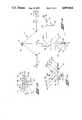
- FIG. 1aschematically illustrates a diffuse reflectance optical system that uses a faceted splitter at a field stop to filter out the specular component of a diffuse reflectance spectrum
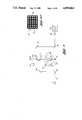
- FIG. 1bis an enlarged detail view of the faceted splitter of FIG. 1a illustrating the energy input to, energy output from and reflectance patterns of the saw tooth reflective surface of the faceted splitter;
- FIG. 1cis a greatly magnified, detail elevation of a sample area having an irregular granular surface at the sample plane of the optical system, the elevation schematically illustrating some input energy that is specularly reflected, some input energy that is specularly scattered and some input energy that is diffusely reflected from the sample;
- FIG. 2is an alternate embodiment of the system shown in FIG. 1 that includes a simplified optics system for macrosampling purposes;
- FIG. 3is an alternate embodiment of the diffuse reflectance optical system shown in FIG. 2 wherein the faceted splitter is replaced with a reflective area beam splitter;
- FIG. 3ais an elevation of a wire grid used as the filter at the field stop plane in the FIG. 3 embodiment.
- FIG. 4is an alternate embodiment of the system shown in FIG. 1 including first and second remote field stop filters and a refractive beam splitter.
- FIG. 1ashows an embodiment of a diffuse reflectance spectroscopy system, indicated generally at 1, that uses a filter or mask at a field stop.
- the system 1includes an energy source 2 directing a beam of energy 3 through the system.
- energy or energy beam as used hereinencompass energies of different wavelengths from visible light through the radiant energy spectrum, with infrared energy being preferred.
- Energy beam 3is reflected from a concave transfer mirror 4 to a focus at a field stop plane 5.
- a filterindicated generally at 6, is positioned at field stop plane 5.
- the filter 6is preferably a faceted beam splitter having input faces reflecting the incident energy in spaced bands in a normal direction from the field stop plane.
- a condensing lens mirror system 8focuses the spatially banded energy at a remote image plane mask 9.
- the energy emanating from the remote image plane mask 9enters a Cassegranian lens, indicated generally at 10.
- the Cassegranian lens 10includes a secondary mirror 12 and a primary mirror 13 operative to focus the incident energy onto a sample area 14 on sample plane 15.
- the sample 14comprises a granulated powder material or a ground material in a matrix.
- the samplemay be a single material or may be comprised of a number of constituent or component materials.
- the sampledoes not have to be specially treated or mixed, but instead can be placed on the sample plane in its untreated state for analysis.
- the filter 6reflects focused, specularly reflected energy back to mirror 4, while directing defocused, primarily diffusely reflected energy to detector 16 by way of concave transfer mirror 17.
- the detector 16receives the diffusely reflected energy and converts the same into spectroscopic data about the sample area, the data being available to the researcher for analysis at the data terminal 18. From this diffuse reflectance data, the researcher can identify the composition of the sample and its constituents, including the concentration percentages of those constituents.
- the image of the incident reflective face of faceted splitter or filter 6 at field stop plane 5is spatially defined or imaged at remote image plane mask 9 before being imaged onto sample 14 at sample plane 15.
- the energyforms an odd number of image planes so that energy that is specularly reflected from sample 14 returns to the incident face of the faceted splitter from which it was originally reflected.
- the focused energy returned from the sample areais thus reflected by the faceted splitter 6 back to source 2.
- Some defocused energy returned from sample 14is contained in bands between the incident or input faces of the faceted beam splitter and thus strikes other output faces of the faceted splitter 6 for reflection of this defocused energy to output detector 16.
- FIG. 1baids in understanding the structure and operation of faceted splitter 6.
- the faceted splitter 6includes a body 20 having a saw tooth edge or cross section forming a plurality of parallel input faces 21 and a plurality of parallel output faces 22.
- the input faces 21are inclined at an angle ⁇ 1 relative to a normal to the field stop plane output faces 22 are oppositely inclined at an angle ⁇ 2 relative to the normal.
- the incoming incident energyforms an angle ⁇ with respect to the field stop plane 5.
- the incident energy beam from source 2impinges upon the reflective surfaces on each individual input face 21 in the beam's path.
- the angle of the incident energy ⁇ and input face angle ⁇ 1are chosen such that the radiant energy reflects from the input faces 21 in a direction along the optical path of the system. Since the incident energy is striking a plurality of spaced parallel input faces 21, the normally reflected energy leaves the faceted splitter in a pattern of generally parallel energy bands, schematically illustrated in shaded band areas 23.
- the bands of energy 23are separated by bands 24 without energy from the source, the bands 24 being aligned with output faces 22 which do not reflect energy from the source because of their orientation.
- the image of faceted splitter 6is projected by the banded incident energy 23 onto sample 14 of sample plane 15.
- the splitter imagecomprises a series of energy bands corresponding to the incident reflective surfaces of each incident input face 21 of the faceted splitter.
- FIG. 1caids in understanding the interaction of the radiant energy with the sample surface area of a diffusely reflecting sample which exhibits specular scatter.
- a granular sample surface having an irregular surface contour 25is shown of the type typically encountered with diffusely reflecting material.
- Incident energy bands 23a-dwould be specularly reflected, as though from a mirror, at the sample focal plane to form beams 23a'-d' but for the presence of surface discontinuities or irregularities introduced by the granular nature of the sample.
- the incident energy beamspartially scatter by reason of being irregularly reflected off the contoured surface of each grain near the focal plane as emplified by beams 23a"-d".
- the specularly scattered reflections 23a"-d" off the granulesnormally occur fairly close to the sample focal plane.
- the specularly reflected energy 23a"-dis still mainly in focus with the optic system.
- the specular reflective energy 23a'-d' and specular scattered energy 23"-d"by being in focus retain the information about the image of the splitter at the sample and thus return to the splitter in bands 23a-d to strike the same input faces 21 of the splitter.
- the specular reflections returning from the surface of sample 14are reflected by input faces 21 back toward the source 2 to effectively be discarded or filtered from the system.
- Some of the incident energy 23a-dmay penetrate the surface of sample 14 and invade that sample before being diffusely reflected back out of the sample as schematically illustrated at 23a"'-d"'.
- the diffuse reflectance energy 23a"'-d"'is spread across the entire optical path as it returns through the optical system to the faceted beam splitter for filtering.
- some of the diffusely reflected energy from the sample areawill return to faceted splitter 6 in the bands 24 between the focused energy bands 23.
- This defocused diffusely reflected energy in bands 24appears to emanate from surface areas not excluded by the image of the filter at the sample.
- This defocused or filtered energywill strike output faces 22 on the faceted splitter and be directed to the detector 16.
- faceted splitter 6separates or filters the energy by where the energy emanates from relative to the focused image of the faceted splitter at sample plane 15, so that only the defocused, presumably diffusely reflected radiant energy is reflected to detector 16.
- the relative efficiency of the present invention in separating the specular and diffuse components of the reflective spectrum from the sampledepends on the spacing of the faces 21 and 22 on faceted splitter 6 relative to the depth of penetration of the energy at the sample area compared to the focused image of the splitter at sample plane 15.
- a sample area having shallow depth of energy penetrationrequires that the faces 21 and 22 on faceted splitter 6 be placed closely together so that the surface of the sample area is almost uniformly energized.
- a sample area, which has a large depth of energy penetrationshould have larger faces 21 and 22 separated by larger distances.
- the upper limit of the spacing of the faces of the faceted splitter 6is determined by design and sampling considerations. For example, the size and separation of the faces 21 and 22 of splitter 6 should be correlated to the wave length of the incident energy. In addition, the faces 21 and 22 should be separated by a sufficient distance that the faceted splitter 6 does not produce significant diffraction effects.
- the location of the sampleis particularly critical in that the sample surface must be located at a good quality optical focus.
- One method of positioning the sample at a good focusis to direct visible light along part of the same optical path as the sampling energy and to use the visual observation system shown in FIG. 1a to focus that visible light at the sample plane 15.
- a portion of a beam of visible light 27 from lamp 28reflects off refractive beam splitter 29 to a pivotable mirror 30. If pivotal mirror 30 is arcuately moved into the optical path of the energy as illustrated by the dotted line 30a, the energy from source 1 is blocked and visible light from lamp 28 is reflected off mirror 29. This reflected visible light is focused at remote image plane mask 9 so that secondary mirror 12 and primary mirror 13 focus the visible light onto the same sample plane that the radiant energy is focused upon in the sampling mode. Part of the reflected light passes through refractive beam splitter 29 to mirror 31 where it may be observed with eyepiece 32. In the visible light viewing mode, the user can adjust the mask 9 to vary the size of the opening at the remote image plane to control the size of the surface area being sampled and can vertically adjust the sample plane to bring the optical system into proper focus for subsequent radiant energy sample testing.
- optical system shown in FIG. 1amay comprise either a low magnification sampling system or a high magnification microscope.
- FIG. 2illustrates a simplified version of the system shown in FIG. 1 that is particularly well adapted to macrosampling of sample surface areas for quality control purposes.
- the structural elements in the FIG. 2 embodiment that are common with the structural elements of the FIG. 1 embodimentare identified by the same reference numerals.
- the diffuse reflectance spectroscopy system 1A of FIG. 2is very similar to the FIG. 1 embodiment except that the remote image plane mask and associated lenses are eliminated and the visible viewing system simplified.
- concave transfer mirror 4focuses energy from source 1 onto input faces of faceted splitter 6.
- Secondary mirror 12directs the energy reflected from faceted splitter 6 to primary mirror 13.
- Mirror 13forms an image of faceted splitter 6 on sample 14 at sample plane 15.
- Primary mirror 13collects the energy reflected from sample 14 so that it is returned to faceted splitter 6 by secondary mirror 12.
- the faceted splitter 6separates specularly reflected energy from sample 14 from energy that is diffusely reflected from within the sample area surface as explained above.
- the input faces 21 of the faceted splitterreturn focused energy specularly reflected from the sample to the source while the output faces 22 of the faceted splitter direct unfocused energy diffusely reflected from the sample to the detector 16 by way of concave transfer mirror 17.
- the macrosampling system shown in FIG. 2can also comprise means for automatically positioning a plurality of samples 14 at the focus of primary mirror 13. For example, samples 14 may be sequentially moved into position on an endless track or conveyor including a plurality of sample holders.
- the optical system of the macrosampling apparatus shown in FIG. 2may be focused in a visible light viewing mode.
- the visible light viewing systemincludes a lamp 28 producing a visible light beam 27, which is reflected along the optical path of the radiant energy by refractive beam splitter 29.
- the eyepiece 32is positioned in axial alignment with that optical path.
- Sample plane 15may be visually observed by pivoting or sliding faceted splitter 6 out of the optical path of eyepiece 32.
- Visible light beam 27reflects off refractive beam splitter 29 to sample plane 15 and returns through refractive beam splitter 29 to eyepiece 32.
- the source of visible lightmay be placed between the primary mirror and the sample so that eyepiece 32 receives a "dark field" view of sample image plane 15.
- Aligned eyepiece 32permits aligning and focusing sample plane 15 and the sample 14 thereon at the focus of primary mirror 13.
- FIG. 3shows an alternate embodiment of the diffuse reflectance spectrometer apparatus shown in FIG. 2 utilizing a different type of filter or mask at the field stop plane.
- Transfer mirrors 35 and 36direct radiant energy 3 from source 2 to a focus at a filter 37, such as an "island" splitter or wire grid.
- the filter 37may take numerous forms having different patterns of reflective surfaces or different patterns of reflective surface areas coupled with transmissive surface areas or open areas. As shown for example in FIG. 3a, the filter 37 may have a crossing grid of reflective wires 38 defining a pattern of open transmissive areas 39.
- the reflective wires 38are analogous to input faces 21 on splitter 6 while open transmissive areas 39 are analogous to output faces 22.
- the incident energy reflected in patterned bands from filter 37enter secondary mirror 12 and primary mirror 13 of Cassegranian lens 10 to focus the diverging beam of banded radiant energy at sample plane 15.
- a focused image of the filter 37is formed at the sample plane 15 by the energy striking the sample 14.
- Incident radiant energy that is specularly reflected from the sample 14 at sample plane 15is imaged onto the reflective regions of filter 37 so as to be lost from the system by being reflected back toward source 2. As described above, some of the incident radiant energy that is diffusely reflected from the sample is out of focus and passes between the reflective regions of filter 37 to mirror 40. Transfer mirrors 41 and 42 direct the diffusely reflected radiant energy from mirror 40 to detector 16. Reflective area splitter or filter 37 thus functions in much the same manner as the reflective faceted splitter 6 of FIG. 1a except that the diffusely reflected radiant energy passes between the reflective areas rather than reflecting off output faces having reflective surfaces.
- FIG. 3also has a visible light viewing and focusing system as described in conjunction with FIG. 2 including lamp 28, refractive beam splitter 29 and eyepiece 32 axially aligned with the optical path.
- lamp 28refractive beam splitter 29 and eyepiece 32 axially aligned with the optical path.
- mirror 40 and splitter 37are slid or pivoted out of the way, visible light is focused on the sample 14 by Cassegranian lens 10, with the sample image being viewed in eyepiece 32 to allow adjustment of sample plane 15 to bring the optical system into focus.
- FIG. 4shows alternate embodiment of the diffuse reflectance spectrometer apparatus shown in FIGS. 1 through 3 utilizing two filters at two discrete field stop planes and a refractive beam splitter.
- Transfer mirrors 44 and 45direct radiant energy 3 from source 2 to a focus at a first remote field stop plane 47.
- a first filter 48is positioned in the field stop plane in the optical path of the system.
- First filter 48comprises a grid having crossed reflective wires 38 defining open transmissive areas 39 therebetween as illustrated in FIG. 3A.
- first grid filter 48The radiant energy striking the reflective wire grids is discarded from the system.
- the energy passing through the open or transmissive areas 39 in first grid filter 48is directed in discrete energy bands toward refractive beam splitter 50.
- the incident energy bands reflected from refractive beam splitter 50enter secondary mirror 12 and primary mirror 13 of Cassegranian lens 10 to focus the banded radiant energy at the sample 14 on sample plane 15.
- a focused image of the first grid filter 48is formed at the sample plane 15 by the energy striking the sample 14.
- Primary mirror 13collects the energy reflected from sample 14 so that it is returned to refractive beam splitter 50 by secondary mirror 12. Some of the energy reflected from sample 14 passes through the refractive beam splitter 50 to a second wire grid filter 50 positioned at a second remote field stop plane 51.
- the second wire grid filter 50is positioned the same distance from refractive beam splitter 50 as is the first grid filter 48.
- the second grid filter 50is a negative to or a complement of the first grid filter 48 meaning that energy going through the first filter and remaining in focus through the rest of the optical system will be blocked by the reflective wires of the second grid filter 50.
- the specularly scattered and specularly reflected energy from sample 14will remain in focus and will be discarded from the system by being reflected from the wire grids 38 of second filter 50.
- the diffusely reflected energy from sample 14will be spread across the entire reflectance spectrum, with that diffusely reflected energy positioned between the bands of focused energy passing through the open or transmissive areas 39 of second filter 50 to pivotal mirror 52.
- Transfer mirrors 54 and 55direct the diffusely reflected radiant energy from pivotal mirror 52 to detector 16.
- FIG. 4also has a visible light viewing and focusing system as described in conjunction with FIGS. 2 and 3.
- This visible light systemincludes lamp 28, refractive beam splitter 29 and eyepiece 32 axially aligned with the optical path.
- lamp 28refractive beam splitter 29
- eyepiece 32axially aligned with the optical path.
Landscapes
- Physics & Mathematics (AREA)
- Health & Medical Sciences (AREA)
- Life Sciences & Earth Sciences (AREA)
- Chemical & Material Sciences (AREA)
- Analytical Chemistry (AREA)
- Biochemistry (AREA)
- General Health & Medical Sciences (AREA)
- General Physics & Mathematics (AREA)
- Immunology (AREA)
- Pathology (AREA)
- Investigating Or Analysing Materials By Optical Means (AREA)
- Spectrometry And Color Measurement (AREA)
Abstract
Description
Claims (15)
Priority Applications (4)
| Application Number | Priority Date | Filing Date | Title |
|---|---|---|---|
| US07/191,980US4859064A (en) | 1988-05-09 | 1988-05-09 | Diffuse reflectance spectroscopy system and method |
| GB8908422AGB2218535B (en) | 1988-05-09 | 1989-04-13 | Diffuse reflectance spectroscopy system and method |
| DE3913228ADE3913228C2 (en) | 1988-05-09 | 1989-04-21 | Diffuse reflection spectroscopy system and method for obtaining a diffuse reflection spectrum |
| JP1106087AJPH0217427A (en) | 1988-05-09 | 1989-04-27 | Diffusive reflection spectroscopic system |
Applications Claiming Priority (1)
| Application Number | Priority Date | Filing Date | Title |
|---|---|---|---|
| US07/191,980US4859064A (en) | 1988-05-09 | 1988-05-09 | Diffuse reflectance spectroscopy system and method |
Publications (1)
| Publication Number | Publication Date |
|---|---|
| US4859064Atrue US4859064A (en) | 1989-08-22 |
Family
ID=22707719
Family Applications (1)
| Application Number | Title | Priority Date | Filing Date |
|---|---|---|---|
| US07/191,980Expired - LifetimeUS4859064A (en) | 1988-05-09 | 1988-05-09 | Diffuse reflectance spectroscopy system and method |
Country Status (4)
| Country | Link |
|---|---|
| US (1) | US4859064A (en) |
| JP (1) | JPH0217427A (en) |
| DE (1) | DE3913228C2 (en) |
| GB (1) | GB2218535B (en) |
Cited By (59)
| Publication number | Priority date | Publication date | Assignee | Title |
|---|---|---|---|---|
| US5021662A (en)* | 1989-05-19 | 1991-06-04 | Texas Instruments Incorporated | Method and apparatus for real-time in-line material monitoring |
| US5058982A (en)* | 1989-06-21 | 1991-10-22 | Orbot Systems Ltd. | Illumination system and inspection apparatus including same |
| US5120966A (en)* | 1988-07-12 | 1992-06-09 | Dainippon Screen Mfg. Co., Ltd. | Method of and apparatus for measuring film thickness |
| US5262646A (en)* | 1990-07-27 | 1993-11-16 | Booker Graham R | Infra-red scanning microscopy |
| US5518689A (en)* | 1995-09-05 | 1996-05-21 | Bayer Corporation | Diffused light reflectance readhead |
| EP0845103A4 (en)* | 1995-08-09 | 1999-12-15 | Rio Grande Medical Tech Inc | Improved diffuse reflectance monitoring apparatus |
| US6157041A (en)* | 1998-10-13 | 2000-12-05 | Rio Grande Medical Technologies, Inc. | Methods and apparatus for tailoring spectroscopic calibration models |
| US6240306B1 (en) | 1995-08-09 | 2001-05-29 | Rio Grande Medical Technologies, Inc. | Method and apparatus for non-invasive blood analyte measurement with fluid compartment equilibration |
| US6437312B1 (en) | 1999-08-05 | 2002-08-20 | Orbotech, Ltd. | Illumination for inspecting surfaces of articles |
| US6441388B1 (en) | 1998-10-13 | 2002-08-27 | Rio Grande Medical Technologies, Inc. | Methods and apparatus for spectroscopic calibration model transfer |
| US20020171834A1 (en)* | 2001-04-11 | 2002-11-21 | Rowe Robert K. | Encoded variable filter spectrometer |
| US6560352B2 (en) | 1999-10-08 | 2003-05-06 | Lumidigm, Inc. | Apparatus and method of biometric identification or verification of individuals using optical spectroscopy |
| US6574490B2 (en) | 2001-04-11 | 2003-06-03 | Rio Grande Medical Technologies, Inc. | System for non-invasive measurement of glucose in humans |
| US6628809B1 (en) | 1999-10-08 | 2003-09-30 | Lumidigm, Inc. | Apparatus and method for identification of individuals by near-infrared spectrum |
| US6654125B2 (en) | 2002-04-04 | 2003-11-25 | Inlight Solutions, Inc | Method and apparatus for optical spectroscopy incorporating a vertical cavity surface emitting laser (VCSEL) as an interferometer reference |
| US20040033618A1 (en)* | 1998-10-13 | 2004-02-19 | Haass Michael J. | Accommodating subject and instrument variations in spectroscopic determinations |
| US20040092822A1 (en)* | 2002-11-12 | 2004-05-13 | Robinson M. Ries | Diffuse reflectance spectroscopy |
| US6816605B2 (en) | 1999-10-08 | 2004-11-09 | Lumidigm, Inc. | Methods and systems for biometric identification of individuals using linear optical spectroscopy |
| US6847442B1 (en) | 1998-06-16 | 2005-01-25 | Orbotech, Ltd. | Illuminator for inspecting substantially flat surfaces |
| US6862091B2 (en) | 2001-04-11 | 2005-03-01 | Inlight Solutions, Inc. | Illumination device and method for spectroscopic analysis |
| US6865408B1 (en) | 2001-04-11 | 2005-03-08 | Inlight Solutions, Inc. | System for non-invasive measurement of glucose in humans |
| US20050073690A1 (en)* | 2003-10-03 | 2005-04-07 | Abbink Russell E. | Optical spectroscopy incorporating a vertical cavity surface emitting laser (VCSEL) |
| US6983176B2 (en) | 2001-04-11 | 2006-01-03 | Rio Grande Medical Technologies, Inc. | Optically similar reference samples and related methods for multivariate calibration models used in optical spectroscopy |
| US20060002597A1 (en)* | 2003-04-04 | 2006-01-05 | Lumidigm, Inc. | Liveness sensor |
| US7027848B2 (en) | 2002-04-04 | 2006-04-11 | Inlight Solutions, Inc. | Apparatus and method for non-invasive spectroscopic measurement of analytes in tissue using a matched reference analyte |
| US7043288B2 (en) | 2002-04-04 | 2006-05-09 | Inlight Solutions, Inc. | Apparatus and method for spectroscopic analysis of tissue to detect diabetes in an individual |
| US20060211928A1 (en)* | 2002-04-04 | 2006-09-21 | Hull Edward L | Determination of a measure of a glycation end-product or disease state using tissue fluorescence preferentially from the dermis |
| US20060244947A1 (en)* | 2005-04-27 | 2006-11-02 | Lumidigm, Inc. | Multispectral Biometric Sensors |
| US7263213B2 (en) | 2003-12-11 | 2007-08-28 | Lumidigm, Inc. | Methods and systems for estimation of personal characteristics from biometric measurements |
| US20070265532A1 (en)* | 2002-04-04 | 2007-11-15 | Maynard John D | Determination of a Measure of a Glycation End-Product or Disease State Using a Flexible Probe to Determine Tissue Fluorescence of Various Sites |
| US20070276199A1 (en)* | 2002-04-04 | 2007-11-29 | Ediger Marwood N | Determination of a Measure of a Glycation End-Product or Disease State Using Tissue Fluorescence |
| US7347365B2 (en) | 2003-04-04 | 2008-03-25 | Lumidigm, Inc. | Combined total-internal-reflectance and tissue imaging systems and methods |
| US7394919B2 (en) | 2004-06-01 | 2008-07-01 | Lumidigm, Inc. | Multispectral biometric imaging |
| US7460696B2 (en) | 2004-06-01 | 2008-12-02 | Lumidigm, Inc. | Multispectral imaging biometrics |
| US7508965B2 (en) | 2004-06-01 | 2009-03-24 | Lumidigm, Inc. | System and method for robust fingerprint acquisition |
| US7539330B2 (en) | 2004-06-01 | 2009-05-26 | Lumidigm, Inc. | Multispectral liveness determination |
| US7545963B2 (en) | 2003-04-04 | 2009-06-09 | Lumidigm, Inc. | Texture-biometrics sensor |
| US7613504B2 (en) | 2001-06-05 | 2009-11-03 | Lumidigm, Inc. | Spectroscopic cross-channel method and apparatus for improved optical measurements of tissue |
| US7620212B1 (en) | 2002-08-13 | 2009-11-17 | Lumidigm, Inc. | Electro-optical sensor |
| US7627151B2 (en) | 2003-04-04 | 2009-12-01 | Lumidigm, Inc. | Systems and methods for improved biometric feature definition |
| US7668350B2 (en) | 2003-04-04 | 2010-02-23 | Lumidigm, Inc. | Comparative texture analysis of tissue for biometric spoof detection |
| US7671985B1 (en)* | 2006-03-13 | 2010-03-02 | Milan Milosevic | Device for small spot analysis using fiber optic interfaced spectrometers |
| US7751594B2 (en) | 2003-04-04 | 2010-07-06 | Lumidigm, Inc. | White-light spectral biometric sensors |
| US7801339B2 (en) | 2006-07-31 | 2010-09-21 | Lumidigm, Inc. | Biometrics with spatiospectral spoof detection |
| US7804984B2 (en) | 2006-07-31 | 2010-09-28 | Lumidigm, Inc. | Spatial-spectral fingerprint spoof detection |
| US7899217B2 (en) | 2006-07-19 | 2011-03-01 | Lumidign, Inc. | Multibiometric multispectral imager |
| US20110163163A1 (en)* | 2004-06-01 | 2011-07-07 | Lumidigm, Inc. | Multispectral barcode imaging |
| US7995808B2 (en) | 2006-07-19 | 2011-08-09 | Lumidigm, Inc. | Contactless multispectral biometric capture |
| US8131332B2 (en) | 2002-04-04 | 2012-03-06 | Veralight, Inc. | Determination of a measure of a glycation end-product or disease state using tissue fluorescence of various sites |
| US8175346B2 (en) | 2006-07-19 | 2012-05-08 | Lumidigm, Inc. | Whole-hand multispectral biometric imaging |
| RU2449771C2 (en)* | 2004-06-09 | 2012-05-10 | Смитклайн Бичам Корпорейшн | Device and method of pharmaceutical production |
| US8229185B2 (en) | 2004-06-01 | 2012-07-24 | Lumidigm, Inc. | Hygienic biometric sensors |
| US8285010B2 (en) | 2007-03-21 | 2012-10-09 | Lumidigm, Inc. | Biometrics based on locally consistent features |
| US8355545B2 (en) | 2007-04-10 | 2013-01-15 | Lumidigm, Inc. | Biometric detection using spatial, temporal, and/or spectral techniques |
| US8570149B2 (en) | 2010-03-16 | 2013-10-29 | Lumidigm, Inc. | Biometric imaging using an optical adaptive interface |
| US8576402B2 (en) | 2010-07-22 | 2013-11-05 | Avago Technologies General Ip (Singapore) Pte. Ltd. | Optical navigation with specular reflection blocking |
| US8731250B2 (en) | 2009-08-26 | 2014-05-20 | Lumidigm, Inc. | Multiplexed biometric imaging |
| US8787630B2 (en) | 2004-08-11 | 2014-07-22 | Lumidigm, Inc. | Multispectral barcode imaging |
| CN108333147A (en)* | 2017-12-14 | 2018-07-27 | 中国科学院西安光学精密机械研究所 | Near back scattering optical measurement system |
Families Citing this family (3)
| Publication number | Priority date | Publication date | Assignee | Title |
|---|---|---|---|---|
| JPH0445231U (en)* | 1990-08-20 | 1992-04-16 | ||
| DE10210436A1 (en)* | 2002-03-09 | 2003-10-02 | Michael Licht | Determining the concentration of an analyte comprises irradiating a sample with polarized light through a magnetic field and measuring reflected/scattered light absorption as a function of polarization angle |
| CN107966277B (en)* | 2017-12-14 | 2023-12-08 | 中国科学院西安光学精密机械研究所 | Near back scattered light time measurement system based on ellipsoidal diffuse reflection whiteboard |
Citations (4)
| Publication number | Priority date | Publication date | Assignee | Title |
|---|---|---|---|---|
| US3229564A (en)* | 1961-05-12 | 1966-01-18 | Bausch & Lomb | Reflectometer |
| US4360275A (en)* | 1980-08-11 | 1982-11-23 | Litton Systems Inc. | Device for measurement of optical scattering |
| US4464050A (en)* | 1981-02-07 | 1984-08-07 | Olympus Optical Co., Ltd. | Apparatus for detecting optically defects |
| US4661706A (en)* | 1985-02-25 | 1987-04-28 | Spectra-Tech Inc. | Blocker device for eliminating specular reflectance from a diffuse reflection spectrum |
Family Cites Families (4)
| Publication number | Priority date | Publication date | Assignee | Title |
|---|---|---|---|---|
| JPS6089732A (en)* | 1983-10-21 | 1985-05-20 | Mitsubishi Heavy Ind Ltd | Automatic sample feeder of diffuse reflection device |
| DE3338967A1 (en)* | 1983-10-27 | 1985-05-09 | M.A.N. Maschinenfabrik Augsburg-Nürnberg AG, 8000 München | Beam splitter |
| JPS6260075A (en)* | 1985-09-10 | 1987-03-16 | Hitachi Ltd | Shape recognizing device |
| DD259453A1 (en)* | 1987-04-06 | 1988-08-24 | Akad Wissenschaften Ddr | MEASURING DEVICE FOR DIFFUSE REFLECTION SPECTROSCOPY IN THE IR-SPECTRAL AREA |
- 1988
- 1988-05-09USUS07/191,980patent/US4859064A/ennot_activeExpired - Lifetime
- 1989
- 1989-04-13GBGB8908422Apatent/GB2218535B/ennot_activeExpired - Fee Related
- 1989-04-21DEDE3913228Apatent/DE3913228C2/ennot_activeExpired - Fee Related
- 1989-04-27JPJP1106087Apatent/JPH0217427A/enactivePending
Patent Citations (4)
| Publication number | Priority date | Publication date | Assignee | Title |
|---|---|---|---|---|
| US3229564A (en)* | 1961-05-12 | 1966-01-18 | Bausch & Lomb | Reflectometer |
| US4360275A (en)* | 1980-08-11 | 1982-11-23 | Litton Systems Inc. | Device for measurement of optical scattering |
| US4464050A (en)* | 1981-02-07 | 1984-08-07 | Olympus Optical Co., Ltd. | Apparatus for detecting optically defects |
| US4661706A (en)* | 1985-02-25 | 1987-04-28 | Spectra-Tech Inc. | Blocker device for eliminating specular reflectance from a diffuse reflection spectrum |
Cited By (91)
| Publication number | Priority date | Publication date | Assignee | Title |
|---|---|---|---|---|
| US5120966A (en)* | 1988-07-12 | 1992-06-09 | Dainippon Screen Mfg. Co., Ltd. | Method of and apparatus for measuring film thickness |
| US5021662A (en)* | 1989-05-19 | 1991-06-04 | Texas Instruments Incorporated | Method and apparatus for real-time in-line material monitoring |
| US5058982A (en)* | 1989-06-21 | 1991-10-22 | Orbot Systems Ltd. | Illumination system and inspection apparatus including same |
| US5262646A (en)* | 1990-07-27 | 1993-11-16 | Booker Graham R | Infra-red scanning microscopy |
| EP0845103A4 (en)* | 1995-08-09 | 1999-12-15 | Rio Grande Medical Tech Inc | Improved diffuse reflectance monitoring apparatus |
| US6622033B2 (en) | 1995-08-09 | 2003-09-16 | Inlight Solutions, Inc. | Diffuse reflectance monitoring apparatus |
| US6230034B1 (en) | 1995-08-09 | 2001-05-08 | Rio Grande Medical Technologies, Inc. | Diffuse reflectance monitoring apparatus |
| US6240306B1 (en) | 1995-08-09 | 2001-05-29 | Rio Grande Medical Technologies, Inc. | Method and apparatus for non-invasive blood analyte measurement with fluid compartment equilibration |
| US6718189B2 (en) | 1995-08-09 | 2004-04-06 | Rio Grande Medical Technologies, Inc. | Method and apparatus for non-invasive blood analyte measurement with fluid compartment equilibration |
| US5518689A (en)* | 1995-09-05 | 1996-05-21 | Bayer Corporation | Diffused light reflectance readhead |
| US9487398B2 (en) | 1997-06-09 | 2016-11-08 | Hid Global Corporation | Apparatus and method of biometric determination using specialized optical spectroscopy systems |
| US20060152728A1 (en)* | 1998-06-16 | 2006-07-13 | Orbotech Ltd. | Illuminator for inspecting substantially flat surfaces |
| US6847442B1 (en) | 1998-06-16 | 2005-01-25 | Orbotech, Ltd. | Illuminator for inspecting substantially flat surfaces |
| US7215417B2 (en) | 1998-06-16 | 2007-05-08 | Orbotech Ltd. | Illuminator for inspecting substantially flat surfaces |
| US6528809B1 (en) | 1998-10-13 | 2003-03-04 | Rio Grande Medical Technologies, Inc. | Methods and apparatus for tailoring spectroscopic calibration models |
| US20040033618A1 (en)* | 1998-10-13 | 2004-02-19 | Haass Michael J. | Accommodating subject and instrument variations in spectroscopic determinations |
| US6441388B1 (en) | 1998-10-13 | 2002-08-27 | Rio Grande Medical Technologies, Inc. | Methods and apparatus for spectroscopic calibration model transfer |
| US7098037B2 (en) | 1998-10-13 | 2006-08-29 | Inlight Solutions, Inc. | Accommodating subject and instrument variations in spectroscopic determinations |
| US6157041A (en)* | 1998-10-13 | 2000-12-05 | Rio Grande Medical Technologies, Inc. | Methods and apparatus for tailoring spectroscopic calibration models |
| US6832843B2 (en) | 1999-08-05 | 2004-12-21 | Orbotech, Ltd. | Illumination for inspecting surfaces of articles |
| US6437312B1 (en) | 1999-08-05 | 2002-08-20 | Orbotech, Ltd. | Illumination for inspecting surfaces of articles |
| US6560352B2 (en) | 1999-10-08 | 2003-05-06 | Lumidigm, Inc. | Apparatus and method of biometric identification or verification of individuals using optical spectroscopy |
| US6628809B1 (en) | 1999-10-08 | 2003-09-30 | Lumidigm, Inc. | Apparatus and method for identification of individuals by near-infrared spectrum |
| US7203345B2 (en) | 1999-10-08 | 2007-04-10 | Lumidigm, Inc. | Apparatus and method for identification of individuals by near-infrared spectrum |
| US6816605B2 (en) | 1999-10-08 | 2004-11-09 | Lumidigm, Inc. | Methods and systems for biometric identification of individuals using linear optical spectroscopy |
| US20020171834A1 (en)* | 2001-04-11 | 2002-11-21 | Rowe Robert K. | Encoded variable filter spectrometer |
| US7126682B2 (en) | 2001-04-11 | 2006-10-24 | Rio Grande Medical Technologies, Inc. | Encoded variable filter spectrometer |
| US6983176B2 (en) | 2001-04-11 | 2006-01-03 | Rio Grande Medical Technologies, Inc. | Optically similar reference samples and related methods for multivariate calibration models used in optical spectroscopy |
| US6574490B2 (en) | 2001-04-11 | 2003-06-03 | Rio Grande Medical Technologies, Inc. | System for non-invasive measurement of glucose in humans |
| US6862091B2 (en) | 2001-04-11 | 2005-03-01 | Inlight Solutions, Inc. | Illumination device and method for spectroscopic analysis |
| US6865408B1 (en) | 2001-04-11 | 2005-03-08 | Inlight Solutions, Inc. | System for non-invasive measurement of glucose in humans |
| US7613504B2 (en) | 2001-06-05 | 2009-11-03 | Lumidigm, Inc. | Spectroscopic cross-channel method and apparatus for improved optical measurements of tissue |
| US7890158B2 (en) | 2001-06-05 | 2011-02-15 | Lumidigm, Inc. | Apparatus and method of biometric determination using specialized optical spectroscopy systems |
| US8121671B2 (en) | 2002-04-04 | 2012-02-21 | Veralight, Inc. | Determination of a measure of a glycation end-product or disease state using tissue fluorescence preferentially from the dermis |
| US8078243B2 (en) | 2002-04-04 | 2011-12-13 | Veralight, Inc. | Determination of a measure of a glycation end-product or disease state using tissue fluorescence |
| US8131332B2 (en) | 2002-04-04 | 2012-03-06 | Veralight, Inc. | Determination of a measure of a glycation end-product or disease state using tissue fluorescence of various sites |
| US8140147B2 (en) | 2002-04-04 | 2012-03-20 | Veralight, Inc. | Determination of a measure of a glycation end-product or disease state using a flexible probe to determine tissue fluorescence of various sites |
| US6654125B2 (en) | 2002-04-04 | 2003-11-25 | Inlight Solutions, Inc | Method and apparatus for optical spectroscopy incorporating a vertical cavity surface emitting laser (VCSEL) as an interferometer reference |
| US20070088205A1 (en)* | 2002-04-04 | 2007-04-19 | Hull Edward L | Determination of a Measure of a Glycation End-Product or Disease State Using Tissue Fluorescence |
| US7043288B2 (en) | 2002-04-04 | 2006-05-09 | Inlight Solutions, Inc. | Apparatus and method for spectroscopic analysis of tissue to detect diabetes in an individual |
| US20060211928A1 (en)* | 2002-04-04 | 2006-09-21 | Hull Edward L | Determination of a measure of a glycation end-product or disease state using tissue fluorescence preferentially from the dermis |
| US20070265532A1 (en)* | 2002-04-04 | 2007-11-15 | Maynard John D | Determination of a Measure of a Glycation End-Product or Disease State Using a Flexible Probe to Determine Tissue Fluorescence of Various Sites |
| US20070276199A1 (en)* | 2002-04-04 | 2007-11-29 | Ediger Marwood N | Determination of a Measure of a Glycation End-Product or Disease State Using Tissue Fluorescence |
| US7027848B2 (en) | 2002-04-04 | 2006-04-11 | Inlight Solutions, Inc. | Apparatus and method for non-invasive spectroscopic measurement of analytes in tissue using a matched reference analyte |
| US7620212B1 (en) | 2002-08-13 | 2009-11-17 | Lumidigm, Inc. | Electro-optical sensor |
| US20040092822A1 (en)* | 2002-11-12 | 2004-05-13 | Robinson M. Ries | Diffuse reflectance spectroscopy |
| US7623906B2 (en) | 2002-11-12 | 2009-11-24 | Inlight Solutions, Inc | Diffuse reflectance spectroscopy |
| US7386152B2 (en) | 2003-04-04 | 2008-06-10 | Lumidigm, Inc. | Noninvasive alcohol sensor |
| US7819311B2 (en) | 2003-04-04 | 2010-10-26 | Lumidigm, Inc. | Multispectral biometric sensor |
| US20060002597A1 (en)* | 2003-04-04 | 2006-01-05 | Lumidigm, Inc. | Liveness sensor |
| US7545963B2 (en) | 2003-04-04 | 2009-06-09 | Lumidigm, Inc. | Texture-biometrics sensor |
| US7147153B2 (en) | 2003-04-04 | 2006-12-12 | Lumidigm, Inc. | Multispectral biometric sensor |
| US7440597B2 (en) | 2003-04-04 | 2008-10-21 | Rowe Robert K | Liveness sensor |
| US7347365B2 (en) | 2003-04-04 | 2008-03-25 | Lumidigm, Inc. | Combined total-internal-reflectance and tissue imaging systems and methods |
| US7627151B2 (en) | 2003-04-04 | 2009-12-01 | Lumidigm, Inc. | Systems and methods for improved biometric feature definition |
| US7668350B2 (en) | 2003-04-04 | 2010-02-23 | Lumidigm, Inc. | Comparative texture analysis of tissue for biometric spoof detection |
| US8184873B2 (en) | 2003-04-04 | 2012-05-22 | Lumidigm, Inc. | White-light spectral biometric sensors |
| US7735729B2 (en) | 2003-04-04 | 2010-06-15 | Lumidigm, Inc. | Biometric sensor |
| US7751594B2 (en) | 2003-04-04 | 2010-07-06 | Lumidigm, Inc. | White-light spectral biometric sensors |
| US20050073690A1 (en)* | 2003-10-03 | 2005-04-07 | Abbink Russell E. | Optical spectroscopy incorporating a vertical cavity surface emitting laser (VCSEL) |
| US7263213B2 (en) | 2003-12-11 | 2007-08-28 | Lumidigm, Inc. | Methods and systems for estimation of personal characteristics from biometric measurements |
| US20110163163A1 (en)* | 2004-06-01 | 2011-07-07 | Lumidigm, Inc. | Multispectral barcode imaging |
| US7508965B2 (en) | 2004-06-01 | 2009-03-24 | Lumidigm, Inc. | System and method for robust fingerprint acquisition |
| US7831072B2 (en) | 2004-06-01 | 2010-11-09 | Lumidigm, Inc. | Multispectral imaging biometrics |
| US7835554B2 (en) | 2004-06-01 | 2010-11-16 | Lumidigm, Inc. | Multispectral imaging biometrics |
| US7394919B2 (en) | 2004-06-01 | 2008-07-01 | Lumidigm, Inc. | Multispectral biometric imaging |
| US8229185B2 (en) | 2004-06-01 | 2012-07-24 | Lumidigm, Inc. | Hygienic biometric sensors |
| US8913800B2 (en) | 2004-06-01 | 2014-12-16 | Lumidigm, Inc. | Optical biometrics imaging with films |
| US8165357B2 (en) | 2004-06-01 | 2012-04-24 | Lumidigm, Inc. | Two camera biometric imaging |
| US7539330B2 (en) | 2004-06-01 | 2009-05-26 | Lumidigm, Inc. | Multispectral liveness determination |
| US7460696B2 (en) | 2004-06-01 | 2008-12-02 | Lumidigm, Inc. | Multispectral imaging biometrics |
| RU2449771C2 (en)* | 2004-06-09 | 2012-05-10 | Смитклайн Бичам Корпорейшн | Device and method of pharmaceutical production |
| US8787630B2 (en) | 2004-08-11 | 2014-07-22 | Lumidigm, Inc. | Multispectral barcode imaging |
| US20060244947A1 (en)* | 2005-04-27 | 2006-11-02 | Lumidigm, Inc. | Multispectral Biometric Sensors |
| US7801338B2 (en) | 2005-04-27 | 2010-09-21 | Lumidigm, Inc. | Multispectral biometric sensors |
| US7671985B1 (en)* | 2006-03-13 | 2010-03-02 | Milan Milosevic | Device for small spot analysis using fiber optic interfaced spectrometers |
| US7995808B2 (en) | 2006-07-19 | 2011-08-09 | Lumidigm, Inc. | Contactless multispectral biometric capture |
| US8831297B2 (en) | 2006-07-19 | 2014-09-09 | Lumidigm, Inc. | Contactless multispectral biometric capture |
| US8175346B2 (en) | 2006-07-19 | 2012-05-08 | Lumidigm, Inc. | Whole-hand multispectral biometric imaging |
| US8781181B2 (en) | 2006-07-19 | 2014-07-15 | Lumidigm, Inc. | Contactless multispectral biometric capture |
| US7899217B2 (en) | 2006-07-19 | 2011-03-01 | Lumidign, Inc. | Multibiometric multispectral imager |
| US7801339B2 (en) | 2006-07-31 | 2010-09-21 | Lumidigm, Inc. | Biometrics with spatiospectral spoof detection |
| US7804984B2 (en) | 2006-07-31 | 2010-09-28 | Lumidigm, Inc. | Spatial-spectral fingerprint spoof detection |
| US8285010B2 (en) | 2007-03-21 | 2012-10-09 | Lumidigm, Inc. | Biometrics based on locally consistent features |
| US8355545B2 (en) | 2007-04-10 | 2013-01-15 | Lumidigm, Inc. | Biometric detection using spatial, temporal, and/or spectral techniques |
| US8872908B2 (en) | 2009-08-26 | 2014-10-28 | Lumidigm, Inc | Dual-imager biometric sensor |
| US8731250B2 (en) | 2009-08-26 | 2014-05-20 | Lumidigm, Inc. | Multiplexed biometric imaging |
| US8570149B2 (en) | 2010-03-16 | 2013-10-29 | Lumidigm, Inc. | Biometric imaging using an optical adaptive interface |
| US8576402B2 (en) | 2010-07-22 | 2013-11-05 | Avago Technologies General Ip (Singapore) Pte. Ltd. | Optical navigation with specular reflection blocking |
| CN108333147A (en)* | 2017-12-14 | 2018-07-27 | 中国科学院西安光学精密机械研究所 | Near back scattering optical measurement system |
| CN108333147B (en)* | 2017-12-14 | 2024-04-12 | 中国科学院西安光学精密机械研究所 | Near back scattering optical measurement system |
Also Published As
| Publication number | Publication date |
|---|---|
| JPH0217427A (en) | 1990-01-22 |
| GB8908422D0 (en) | 1989-06-01 |
| DE3913228C2 (en) | 1998-04-09 |
| DE3913228A1 (en) | 1989-11-23 |
| GB2218535A (en) | 1989-11-15 |
| GB2218535B (en) | 1991-11-13 |
Similar Documents
| Publication | Publication Date | Title |
|---|---|---|
| US4859064A (en) | Diffuse reflectance spectroscopy system and method | |
| US5604585A (en) | Particle detection system employing a subsystem for collecting scattered light from the particles | |
| US6686602B2 (en) | Patterned wafer inspection using spatial filtering | |
| US7304735B2 (en) | Broadband wavelength selective filter | |
| US5241369A (en) | Two-dimensional optical scatterometer apparatus and process | |
| US5805278A (en) | Particle detection method and apparatus | |
| US5623342A (en) | Raman microscope | |
| WO1996030747A9 (en) | Particle detection system employing a subsystem for collecting scattered light from the particles | |
| EP2160591B1 (en) | Imaging optical inspection device with a pinhole camera | |
| US4810077A (en) | Grazing angle microscope | |
| JPS61212733A (en) | Method of orienting beam and reflected-beam spectral device | |
| JPH06129979A (en) | Radiant energy spectrometer | |
| JPH04171415A (en) | Long-focus depth high-resolution irradiating optical system | |
| US6879391B1 (en) | Particle detection method and apparatus | |
| DE19828547C2 (en) | Arrangement for the detection of biomolecular reactions and interactions | |
| US20050146719A1 (en) | Method and apparatus for illuminating a substrate during inspection | |
| US7274445B1 (en) | Confocal scatterometer and method for single-sided detection of particles and defects on a transparent wafer or disk | |
| KR100829658B1 (en) | Wafer inspection system for irradiation at variable angles | |
| US3806257A (en) | Operator viewing optics for a slide classification system | |
| US4351611A (en) | Monitoring of a detection zone utilizing zero order radiation from a concave reflecting grating | |
| EP0327499B1 (en) | Measuring head | |
| JPH063625A (en) | Inspection device | |
| CA2200446A1 (en) | Method and apparatus for image plane modulation pattern recognition | |
| US20040196460A1 (en) | Scatterometric measuring arrangement and measuring method | |
| JPH07198620A (en) | Inspection device |
Legal Events
| Date | Code | Title | Description |
|---|---|---|---|
| AS | Assignment | Owner name:SPECTRA-TECH, INC., 652 GLENBROOK, P.O. BOX 2190, Free format text:ASSIGNMENT OF ASSIGNORS INTEREST.;ASSIGNORS:MESSERSCHMIDT, ROBERT G.;STING, DONALD W.;REEL/FRAME:004889/0130 Effective date:19880506 Owner name:SPECTRA-TECH, INC., A CORP. OF DE., CONNECTICUT Free format text:ASSIGNMENT OF ASSIGNORS INTEREST;ASSIGNORS:MESSERSCHMIDT, ROBERT G.;STING, DONALD W.;REEL/FRAME:004889/0130 Effective date:19880506 | |
| STCF | Information on status: patent grant | Free format text:PATENTED CASE | |
| FEPP | Fee payment procedure | Free format text:PAT HLDR NO LONGER CLAIMS SMALL ENT STAT AS SMALL BUSINESS (ORIGINAL EVENT CODE: LSM2); ENTITY STATUS OF PATENT OWNER: LARGE ENTITY | |
| FEPP | Fee payment procedure | Free format text:PAYER NUMBER DE-ASSIGNED (ORIGINAL EVENT CODE: RMPN); ENTITY STATUS OF PATENT OWNER: LARGE ENTITY Free format text:PAYOR NUMBER ASSIGNED (ORIGINAL EVENT CODE: ASPN); ENTITY STATUS OF PATENT OWNER: LARGE ENTITY | |
| FPAY | Fee payment | Year of fee payment:4 | |
| FEPP | Fee payment procedure | Free format text:PAT HOLDER CLAIMS SMALL ENTITY STATUS - SMALL BUSINESS (ORIGINAL EVENT CODE: SM02); ENTITY STATUS OF PATENT OWNER: LARGE ENTITY Free format text:PAYOR NUMBER ASSIGNED (ORIGINAL EVENT CODE: ASPN); ENTITY STATUS OF PATENT OWNER: LARGE ENTITY | |
| FPAY | Fee payment | Year of fee payment:8 | |
| FEPP | Fee payment procedure | Free format text:PAT HLDR NO LONGER CLAIMS SMALL ENT STAT AS SMALL BUSINESS (ORIGINAL EVENT CODE: LSM2); ENTITY STATUS OF PATENT OWNER: LARGE ENTITY | |
| FPAY | Fee payment | Year of fee payment:12 | |
| DD | Disclaimer and dedication filed | Free format text:20010615 |