US4858967A - High pressure hose fitting and method for sealing high pressure hoses to fittings - Google Patents
High pressure hose fitting and method for sealing high pressure hoses to fittingsDownload PDFInfo
- Publication number
- US4858967A US4858967AUS07/180,546US18054688AUS4858967AUS 4858967 AUS4858967 AUS 4858967AUS 18054688 AUS18054688 AUS 18054688AUS 4858967 AUS4858967 AUS 4858967A
- Authority
- US
- United States
- Prior art keywords
- liner
- hose
- flange
- protruding
- reinforcement layer
- Prior art date
- Legal status (The legal status is an assumption and is not a legal conclusion. Google has not performed a legal analysis and makes no representation as to the accuracy of the status listed.)
- Expired - Fee Related
Links
- 238000000034methodMethods0.000titleclaimsabstractdescription8
- 238000007789sealingMethods0.000titleabstractdescription8
- 230000002787reinforcementEffects0.000claimsabstractdescription31
- 239000012530fluidSubstances0.000claimsdescription13
- 230000008878couplingEffects0.000claimsdescription5
- 238000010168coupling processMethods0.000claimsdescription5
- 238000005859coupling reactionMethods0.000claimsdescription5
- 230000003014reinforcing effectEffects0.000claimsdescription4
- 239000010410layerSubstances0.000claims12
- 239000011241protective layerSubstances0.000claims3
- 230000004888barrier functionEffects0.000claims2
- 239000000463materialSubstances0.000description7
- XLYOFNOQVPJJNP-UHFFFAOYSA-NwaterSubstancesOXLYOFNOQVPJJNP-UHFFFAOYSA-N0.000description4
- 239000002184metalSubstances0.000description3
- 229910000851Alloy steelInorganic materials0.000description2
- 238000004891communicationMethods0.000description2
- 229920001971elastomerPolymers0.000description2
- 239000000806elastomerSubstances0.000description2
- 239000004677NylonSubstances0.000description1
- 239000004809TeflonSubstances0.000description1
- 229920006362Teflon®Polymers0.000description1
- 230000007547defectEffects0.000description1
- 238000013461designMethods0.000description1
- 230000000694effectsEffects0.000description1
- 238000003780insertionMethods0.000description1
- 230000037431insertionEffects0.000description1
- 238000012986modificationMethods0.000description1
- 230000004048modificationEffects0.000description1
- 210000002445nippleAnatomy0.000description1
- 229920001778nylonPolymers0.000description1
- 229920000642polymerPolymers0.000description1
Images
Classifications
- F—MECHANICAL ENGINEERING; LIGHTING; HEATING; WEAPONS; BLASTING
- F16—ENGINEERING ELEMENTS AND UNITS; GENERAL MEASURES FOR PRODUCING AND MAINTAINING EFFECTIVE FUNCTIONING OF MACHINES OR INSTALLATIONS; THERMAL INSULATION IN GENERAL
- F16L—PIPES; JOINTS OR FITTINGS FOR PIPES; SUPPORTS FOR PIPES, CABLES OR PROTECTIVE TUBING; MEANS FOR THERMAL INSULATION IN GENERAL
- F16L33/00—Arrangements for connecting hoses to rigid members; Rigid hose-connectors, i.e. single members engaging both hoses
- F16L33/20—Undivided rings, sleeves, or like members contracted on the hose or expanded inside the hose by means of tools; Arrangements using such members
- F16L33/207—Undivided rings, sleeves, or like members contracted on the hose or expanded inside the hose by means of tools; Arrangements using such members only a sleeve being contracted on the hose
- F16L33/2071—Undivided rings, sleeves, or like members contracted on the hose or expanded inside the hose by means of tools; Arrangements using such members only a sleeve being contracted on the hose the sleeve being a separate connecting member
- F16L33/2073—Undivided rings, sleeves, or like members contracted on the hose or expanded inside the hose by means of tools; Arrangements using such members only a sleeve being contracted on the hose the sleeve being a separate connecting member directly connected to the rigid member
- F16L33/2076—Undivided rings, sleeves, or like members contracted on the hose or expanded inside the hose by means of tools; Arrangements using such members only a sleeve being contracted on the hose the sleeve being a separate connecting member directly connected to the rigid member by plastic deformation
Definitions
- This inventionrelates to tubular conduits and specifically to the end structures thereof. More specifically, this invention relates to an end fitting for use with high pressure hoses and to a method for sealing high pressure hoses to fittings.
- high pressureis used to denote pressures in excess of 20,000 psi. Pressures in excess of 20,000 psi are experienced in a number of technical areas including, but not limited to, high pressure water jet cutting. Although this particular application will be used as an example throughout this specification, it should be understood that the described invention is not so limited.
- High pressure water jet cutting systemstypically compress water, or other convenient fluid, to working pressures in excess of 20,000 psi. Some of the systems, such as those manufactured by Flow Systems, Inc., in Kent Washington, operate at working pressures in the range of 40,000 to 60,000 psi. Although the highest burst pressure dealt with in SAE specifications for hoses is in SAE 100R11 for a 3/16 inch I.D. hose, hoses capable of carrying the pressurized fluid in a water jet cutting system should preferably have burst pressures in the range of 100,000-110,000 psi.
- the high pressure hoses of the type described abovecomprise an axially-extending liner of generally annular cross-section generally circumventing the hoses' passageway, and an axially extending reinforcement layer generally circumventing the liner.
- the lineris typically formed from an elastomer or polymer.
- the reinforcement layeris typically formed by as many as eight wraps of wire, each of which circumvent the exterior of the liner at a different angle to the hose axis than the others.
- the hoseis coupled to the source or destination of the conducted fluid by means of a generally tubular end fitting whose internal passageway is in fluid communication with the hose's passageway.
- the end fittingwhich is typically formed from a metal, has a leading end portion inserted within the end of the hose.
- a metal sleeveis typically used.
- the sleevecircumvents the end of the hose, and is swaged radially inwardly to form the seal.
- U.S. Pat. No. 4,106,526is directed to a high temperature end fitting wherein the inserted end of the end fitting is provided with a series of radially outward projections.
- the swaged sleeveis provided with a corresponding plurality of radially inward projections which cooperated with the outward projections to grip the hose between the projections, compressing the elastomer liner into cells defined by the corresponding inward and outward projections.
- U.S. Pat. No. 3,008,736discloses a hose coupling which is described as a high pressure coupling without any specificity concerning the magnitude of pressure involved.
- the couplingcomprises a guide member which is inserted into the hose, and a tubular connector member circumventing the hose.
- a sharp leading edge of the connector memberseparates the reinforcing layer from the hose liner as the insert and connector are twisted onto the hose.
- the reinforcement layeris thereafter crimped between the connector and an externally mounted ferrule, while the liner is forced by an externally mounted spring into grooves formed on the insert to effect a seal.
- U.S. Pat. No. 2,731,279is directed to a hose coupling wherein a tubular insert fits within the end portion of the hose.
- the tubular insertincludes an externally threaded flange having a sharp-edged, wedge-shaped, axially extending, annular leading edge which is separated from the main body of the insert by a close-ended slot. As the insert is forced into the hose, the annular leading edge cuts into the liner of the hose, creating an annular flap of the liner material which enters the close-ended slot.
- the exterior portion of the liner, overlying the flap, together with the reinforcement layer overlying said exterior portion,is gripped between the sleeve and an externally threaded socket which is tightened onto the flange of the insert.
- the interior of the hoseis described as being sealed by the enclosure of the flap by the opposing walls of the slot.
- the thickness of the reinforcement layermay be sufficiently thin to permit a sufficiently thick liner to be cut by a wedge-shaped member to form a sealable flap.
- a typical hosehas a liner approximately 0.032 inches thick, and a reinforcement layer approximately 0.100 thick.
- the seal described in the patentis ineffective at high pressures of the type to which the present invention is directed.
- the invention hereinprovides a hose end unit comprising an axially extending hose having an inner axially extending passageway, an axially extending liner of generally annular cross-section generally circumventing said passageway, and an axially extending reinforcement layer generally circumventing the liner.
- the hosehas an end portion where the liner extends axially beyond the reinforcing layer, terminating in a protruding end region adjacent said end portion.
- a generally tubular end fittinghas a leading end portion inserted within the end region of the liner.
- the leading portionincludes means for enveloping at least a portion of the protruding end region of the liner.
- a sleeve circumventing the end portion of the hoseis swaged radially inwardly to clamp the liner within the enveloping means of the tubular end fitting. Sealing is thereafter effectuated by the expansion of the liner against the enveloping means in response to fluid pressure within the hose.
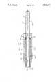
- FIGUREis a longitudinal sectional view, in schematic, of a hose end unit constructed in accordance with the invention.
- the FIGUREis a longitudinal sectional view, in schematic, of a hose end unit constructed in accordance with the invention.
- the illustrated unitcomprises the end portion of a high pressure hose formed from a generally cylindrical liner 30 which generally circumvents the passageway 14 of the hose, and a reinforcement layer 40 which generally circumvents the liner.
- the hoseis illustrated as being disposed about an axis 12.
- the liner 30extends approximately 0.08 inches beyond the end of the reinforcement layer to terminate in a protruding end region 32 axially adjacent the end portion of the hose.
- the linermay be exposed by cutting the reinforcement layer back or by pulling the liner out beyond the end of the hose.
- the lineris preferably formed from a relatively stiff, but stretchable, material such as nylon or teflon and is not bonded to the reinforcement layer.
- the reinforcement layer 40preferably comprises a plurality of layers of helically wound metal wires formed from a high strength steel alloy. Each of the wire layers is preferably wound about the liner at a uniquely different angle, so that the combined multiplicity of angles maximizes the burst strength of the hose.
- a generally tubular end fitting 20has a leading end portion 22 inserted within the end region of the liner
- the end fittingwhich is made of a high strength steel alloy, includes an internal passageway 24 in fluid communication with the hose's passageway 14 after insertion.
- the leading portion of the end fitting 20includes a flange 26 having a generally circumferential liner-receiving groove 50 for receiving and enveloping the protruding end portion 32 of the liner. Specifically the liner is received between the radially inner and outer walls of the groove 50, so that the walls of the groove respectively engage the radially inner and outer surfaces of the liner when the end unit is swaged, as described below.
- the groove 50terminates in a generally concave manner so that the liner end nests against the end of the groove. It is understood that a suitable shaped flange of generally concave shape may instead be provided without departing from the spirit of the invention.
- An annular washer 60is axially positioned at the end region of the hose between the reinforcement layer 40 and the grooved flange 26 of the end fitting 20.
- the internal diameter of the washer 60is sufficiently large to provide a close sliding fit about the liner's protruding end 32.
- the outside diameter of the washer 60is larger than the crimped outside diameter of the reinforcement layer after swaging.
- the washeris, therefore, itself swaged to a smaller diameter on both its inside diameter and outside diameter, thus assuring intimate contact with the outside diameter of the protruding liner end 32.
- a washer having a thickness of 0.030 incheshas been used with satisfactory results.
- the depth of the grooveis preferably sufficient to accommodate the entire portion of the protruding liner which extends from the I.D. of the washer 60. Accordingly, the groove is approximately 0.05 inches deep when the washer and protruding portion 32 of the liner have the aforedescribed dimensions.
- a tubular sleeve 10circumvents the end portion of the hose. After the aforedescribed components have been assembled in the illustrated manner, the sleeve 10 is swaged radially inwardly to clamp the leading portion of the end fitting to the liner, and to clamp the hose nipple and sleeve together.
- the closed-ended groove 50wraps around the end of the liner 30 and seals the liner on its outside diameter.
- the aforedescribed unitutilizes the pressure of the conducted fluid to expand the liner and seal it against the outside diameter of the groove 50. Accordingly, it is desirable that the outer surface of the protruding liner be free of defects which inhibit sealing contact by the groove wall, and some degree of surface smoothening may be performed as required.
- the washer 60prevents the fluidized liner material from extruding into any gap between the reinforcement layer 40 and the flange 26 of the end fitting 20, and pushing the inner layers of the helically wound wires back from the groove. Under such circumstances, the outer surface of the protruding liner material becomes unsupported, resulting in ineffective sealing and consequential failure of the unit.
- the washerdisperses any such fluidic force among all the layers of the reinforcement layer, and adds support to the protruding liner material.
- the aforedescribed embodimentprovides a high pressure hose end unit particularly suitable for applications in which the working pressure of the conducted fluid exceeds the yield stress of the liner material, causing the liner material to flow plastically.
Landscapes
- Engineering & Computer Science (AREA)
- General Engineering & Computer Science (AREA)
- Mechanical Engineering (AREA)
- Joints That Cut Off Fluids, And Hose Joints (AREA)
Abstract
Description
Claims (15)
Priority Applications (1)
| Application Number | Priority Date | Filing Date | Title |
|---|---|---|---|
| US07/180,546US4858967A (en) | 1988-04-12 | 1988-04-12 | High pressure hose fitting and method for sealing high pressure hoses to fittings |
Applications Claiming Priority (1)
| Application Number | Priority Date | Filing Date | Title |
|---|---|---|---|
| US07/180,546US4858967A (en) | 1988-04-12 | 1988-04-12 | High pressure hose fitting and method for sealing high pressure hoses to fittings |
Publications (1)
| Publication Number | Publication Date |
|---|---|
| US4858967Atrue US4858967A (en) | 1989-08-22 |
Family
ID=22660848
Family Applications (1)
| Application Number | Title | Priority Date | Filing Date |
|---|---|---|---|
| US07/180,546Expired - Fee RelatedUS4858967A (en) | 1988-04-12 | 1988-04-12 | High pressure hose fitting and method for sealing high pressure hoses to fittings |
Country Status (1)
| Country | Link |
|---|---|
| US (1) | US4858967A (en) |
Cited By (8)
| Publication number | Priority date | Publication date | Assignee | Title |
|---|---|---|---|---|
| US5143409A (en)* | 1989-08-30 | 1992-09-01 | Titeflex Corporation | Stress relief device |
| FR2734337A1 (en)* | 1995-05-19 | 1996-11-22 | Euroflex Sa | Flexible tube assembly provided with end connectors for LPG appliances |
| US20040227346A1 (en)* | 2003-05-15 | 2004-11-18 | Jamison Tommy L. | Fluid conduit system and fittings therefor |
| US20050040646A1 (en)* | 2001-01-12 | 2005-02-24 | Harco Industries, Inc. | Flexible hydraulic brake line assembly for motor vehicle wheels |
| US20060112534A1 (en)* | 2002-09-03 | 2006-06-01 | Roderick Seton-Anderson | End fitting for hose |
| US20070296209A1 (en)* | 2005-10-07 | 2007-12-27 | Flexpipe Systems Inc. | Pipe coupling and method for installation |
| US20110148099A1 (en)* | 2009-12-18 | 2011-06-23 | E.I. Du Pont De Nemours And Company | Low stress hose coupling |
| US12403621B2 (en) | 2019-12-20 | 2025-09-02 | Hypertherm, Inc. | Motorized systems and associated methods for controlling an adjustable dump orifice on a liquid jet cutting system |
Citations (11)
| Publication number | Priority date | Publication date | Assignee | Title |
|---|---|---|---|---|
| US1481341A (en)* | 1920-08-09 | 1924-01-22 | Martin C Bersted | Grease-gun hose coupling |
| US2008175A (en)* | 1933-07-13 | 1935-07-16 | Cowles Irving | Flexible conduit |
| US2463293A (en)* | 1946-02-18 | 1949-03-01 | Weatherhead Co | Hose end |
| US2661225A (en)* | 1950-01-14 | 1953-12-01 | Gilbert T Lyon | Hose clamp fitting connection |
| US2685458A (en)* | 1951-11-03 | 1954-08-03 | Ernest C Shaw | Coupling for hydraulic hose |
| US2687904A (en)* | 1950-12-06 | 1954-08-31 | Appleton Electric Co | Fitting for flexible conduits |
| US2731279A (en)* | 1950-09-14 | 1956-01-17 | Aeroquip Corp | Fitting for reinforced hose |
| US2797111A (en)* | 1952-04-07 | 1957-06-25 | British Tyre & Rubber Company | Fitting for plural layer wire reinforced hoses |
| US3525542A (en)* | 1966-12-01 | 1970-08-25 | Teves Kg Alfred | Tube connector |
| US4106526A (en)* | 1976-04-08 | 1978-08-15 | Btr Industries Limited | High temperature end fitting |
| US4758029A (en)* | 1987-06-12 | 1988-07-19 | Aeroquip Corporation | Segmented fitting for convoluted hose |
- 1988
- 1988-04-12USUS07/180,546patent/US4858967A/ennot_activeExpired - Fee Related
Patent Citations (11)
| Publication number | Priority date | Publication date | Assignee | Title |
|---|---|---|---|---|
| US1481341A (en)* | 1920-08-09 | 1924-01-22 | Martin C Bersted | Grease-gun hose coupling |
| US2008175A (en)* | 1933-07-13 | 1935-07-16 | Cowles Irving | Flexible conduit |
| US2463293A (en)* | 1946-02-18 | 1949-03-01 | Weatherhead Co | Hose end |
| US2661225A (en)* | 1950-01-14 | 1953-12-01 | Gilbert T Lyon | Hose clamp fitting connection |
| US2731279A (en)* | 1950-09-14 | 1956-01-17 | Aeroquip Corp | Fitting for reinforced hose |
| US2687904A (en)* | 1950-12-06 | 1954-08-31 | Appleton Electric Co | Fitting for flexible conduits |
| US2685458A (en)* | 1951-11-03 | 1954-08-03 | Ernest C Shaw | Coupling for hydraulic hose |
| US2797111A (en)* | 1952-04-07 | 1957-06-25 | British Tyre & Rubber Company | Fitting for plural layer wire reinforced hoses |
| US3525542A (en)* | 1966-12-01 | 1970-08-25 | Teves Kg Alfred | Tube connector |
| US4106526A (en)* | 1976-04-08 | 1978-08-15 | Btr Industries Limited | High temperature end fitting |
| US4758029A (en)* | 1987-06-12 | 1988-07-19 | Aeroquip Corporation | Segmented fitting for convoluted hose |
Cited By (12)
| Publication number | Priority date | Publication date | Assignee | Title |
|---|---|---|---|---|
| US5143409A (en)* | 1989-08-30 | 1992-09-01 | Titeflex Corporation | Stress relief device |
| FR2734337A1 (en)* | 1995-05-19 | 1996-11-22 | Euroflex Sa | Flexible tube assembly provided with end connectors for LPG appliances |
| US20050040646A1 (en)* | 2001-01-12 | 2005-02-24 | Harco Industries, Inc. | Flexible hydraulic brake line assembly for motor vehicle wheels |
| US20060112534A1 (en)* | 2002-09-03 | 2006-06-01 | Roderick Seton-Anderson | End fitting for hose |
| US20040227346A1 (en)* | 2003-05-15 | 2004-11-18 | Jamison Tommy L. | Fluid conduit system and fittings therefor |
| US7516990B2 (en)* | 2003-05-15 | 2009-04-14 | Mueller Industries, Inc. | Fluid conduit system and fittings therefor |
| US20070296209A1 (en)* | 2005-10-07 | 2007-12-27 | Flexpipe Systems Inc. | Pipe coupling and method for installation |
| US20100115758A1 (en)* | 2005-10-07 | 2010-05-13 | Flexpipe Systems Inc. | Pipe coupling and method for installation |
| US7946629B2 (en) | 2005-10-07 | 2011-05-24 | Flexpipe Systems Inc. | Pipe coupling and method for installation |
| US8042252B2 (en) | 2005-10-07 | 2011-10-25 | Flexpipe Systems Inc. | Pipe coupling and method for installation |
| US20110148099A1 (en)* | 2009-12-18 | 2011-06-23 | E.I. Du Pont De Nemours And Company | Low stress hose coupling |
| US12403621B2 (en) | 2019-12-20 | 2025-09-02 | Hypertherm, Inc. | Motorized systems and associated methods for controlling an adjustable dump orifice on a liquid jet cutting system |
Similar Documents
| Publication | Publication Date | Title |
|---|---|---|
| US6619701B1 (en) | Connection of a metal pipe with a metal sleeve | |
| EP1680616B1 (en) | Fitting for a flexible metal hose | |
| US4407532A (en) | Hose end fitting | |
| EP0939265B1 (en) | Metal hose fitting and method of making | |
| KR920006814B1 (en) | Fluid fitting with high temperature capabilities | |
| US3423109A (en) | Hose fitting | |
| EP1992860B1 (en) | Non-serviceable fluid coupling | |
| JP5476780B2 (en) | Hose connection method | |
| US4932689A (en) | Hose fitting assembly | |
| EP0828962B1 (en) | Tube fitting and assembly method | |
| KR20190104641A (en) | Push to connect conduit fitting with ferrule | |
| WO1999006748A1 (en) | Pipe coupling method and apparatus | |
| WO2013109522A2 (en) | Fitting for jacketed conduits | |
| WO2008150469A1 (en) | Fitting with bushing for corrugated stainless steel tubing | |
| US20100187815A1 (en) | Hose fitting and method for fastening the hose fitting to a hose | |
| US20030111839A1 (en) | End fitting for tubular members and method of applying same | |
| EP0131076B1 (en) | Ferrule, coupling and coupling process | |
| US4858967A (en) | High pressure hose fitting and method for sealing high pressure hoses to fittings | |
| WO2008118944A2 (en) | Sealing fitting for stainless steel tubing | |
| EP3115655B1 (en) | Integrated metal c-seal with threaded adapter | |
| EP1567799B1 (en) | Hydraulic hose fitting | |
| US8919822B2 (en) | Fitting system for a hydraulic tuning cable | |
| US5508475A (en) | Termination apparatus for conduit, cable, and braided bundle | |
| US5014423A (en) | Method for forming a sealed coupling using a high pressure hose fitting with an O-ring type seal | |
| EP1298376B1 (en) | Structure and method for connecting end fitting to composite hose |
Legal Events
| Date | Code | Title | Description |
|---|---|---|---|
| AS | Assignment | Owner name:FLOW SYSTEMS, 21440 - 68TH AVENUE, SOUTH, KENT WAS Free format text:ASSIGNMENT OF ASSIGNORS INTEREST.;ASSIGNORS:TREMOULET, OLIVER L. JR.;RAGHAVAN, CHIDAMBARAM;REEL/FRAME:004912/0634 Effective date:19880516 Owner name:FLOW SYSTEMS,WASHINGTON Free format text:ASSIGNMENT OF ASSIGNORS INTEREST;ASSIGNORS:TREMOULET, OLIVER L. JR.;RAGHAVAN, CHIDAMBARAM;REEL/FRAME:004912/0634 Effective date:19880516 | |
| REMI | Maintenance fee reminder mailed | ||
| FPAY | Fee payment | Year of fee payment:4 | |
| SULP | Surcharge for late payment | ||
| AS | Assignment | Owner name:FLOW INTERNATIONAL CORPORATION, WASHINGTON Free format text:MERGER;ASSIGNOR:FLOW SYSTEMS, INC.;REEL/FRAME:006748/0467 Effective date:19890307 | |
| FPAY | Fee payment | Year of fee payment:8 | |
| REMI | Maintenance fee reminder mailed | ||
| LAPS | Lapse for failure to pay maintenance fees | ||
| FP | Lapsed due to failure to pay maintenance fee | Effective date:20010822 | |
| AS | Assignment | Owner name:JOHN HANCOCK LIFE INSURANCE COMPANY, AS COLLATERAL Free format text:SECURITY INTEREST;ASSIGNOR:FLOW INTERNATIONAL CORPORATION;REEL/FRAME:013447/0301 Effective date:20021001 | |
| AS | Assignment | Owner name:FLOW INTERNATIONAL CORPORATION, WASHINGTON Free format text:RELEASE BY SECURED PARTY;ASSIGNOR:JOHN HANCOCK LIFE INSURANCE COMPANY;REEL/FRAME:016761/0670 Effective date:20051031 | |
| AS | Assignment | Owner name:BANK OF AMERICA, N.A., WASHINGTON Free format text:SECURITY AGREEMENT;ASSIGNOR:FLOW INTERNATIONAL CORPORATION;REEL/FRAME:021138/0738 Effective date:20080609 Owner name:BANK OF AMERICA, N.A.,WASHINGTON Free format text:SECURITY AGREEMENT;ASSIGNOR:FLOW INTERNATIONAL CORPORATION;REEL/FRAME:021138/0738 Effective date:20080609 | |
| STCH | Information on status: patent discontinuation | Free format text:PATENT EXPIRED DUE TO NONPAYMENT OF MAINTENANCE FEES UNDER 37 CFR 1.362 |