US4858929A - Golf irons - Google Patents
Golf ironsDownload PDFInfo
- Publication number
- US4858929A US4858929AUS07/197,662US19766288AUS4858929AUS 4858929 AUS4858929 AUS 4858929AUS 19766288 AUS19766288 AUS 19766288AUS 4858929 AUS4858929 AUS 4858929A
- Authority
- US
- United States
- Prior art keywords
- iron
- irons
- golf
- face
- mass
- Prior art date
- Legal status (The legal status is an assumption and is not a legal conclusion. Google has not performed a legal analysis and makes no representation as to the accuracy of the status listed.)
- Expired - Fee Related
Links
- 235000000396ironNutrition0.000titleclaimsabstractdescription76
- XEEYBQQBJWHFJM-UHFFFAOYSA-NIronChemical compound[Fe]XEEYBQQBJWHFJM-UHFFFAOYSA-N0.000claimsabstractdescription317
- 229910052742ironInorganic materials0.000claimsabstractdescription159
- 238000006073displacement reactionMethods0.000claimsabstractdescription38
- 230000003247decreasing effectEffects0.000claimsabstractdescription8
- 230000002250progressing effectEffects0.000abstract1
- 239000004576sandSubstances0.000description9
- 230000000750progressive effectEffects0.000description5
- XLYOFNOQVPJJNP-UHFFFAOYSA-NwaterSubstancesOXLYOFNOQVPJJNP-UHFFFAOYSA-N0.000description5
- 230000009471actionEffects0.000description3
- 230000008901benefitEffects0.000description3
- 230000008859changeEffects0.000description3
- 230000003466anti-cipated effectEffects0.000description2
- 230000005465channelingEffects0.000description2
- 239000000463materialSubstances0.000description2
- 230000007935neutral effectEffects0.000description2
- 230000001133accelerationEffects0.000description1
- 230000000694effectsEffects0.000description1
- XEEYBQQBJWHFJM-RNFDNDRNSA-Niron-60Chemical compound[60Fe]XEEYBQQBJWHFJM-RNFDNDRNSA-N0.000description1
- 230000004048modificationEffects0.000description1
- 238000012986modificationMethods0.000description1
- 230000003014reinforcing effectEffects0.000description1
- 230000007704transitionEffects0.000description1
- 210000000707wristAnatomy0.000description1
Images


Classifications
- A—HUMAN NECESSITIES
- A63—SPORTS; GAMES; AMUSEMENTS
- A63B—APPARATUS FOR PHYSICAL TRAINING, GYMNASTICS, SWIMMING, CLIMBING, OR FENCING; BALL GAMES; TRAINING EQUIPMENT
- A63B53/00—Golf clubs
- A63B53/04—Heads
- A—HUMAN NECESSITIES
- A63—SPORTS; GAMES; AMUSEMENTS
- A63B—APPARATUS FOR PHYSICAL TRAINING, GYMNASTICS, SWIMMING, CLIMBING, OR FENCING; BALL GAMES; TRAINING EQUIPMENT
- A63B53/00—Golf clubs
- A—HUMAN NECESSITIES
- A63—SPORTS; GAMES; AMUSEMENTS
- A63B—APPARATUS FOR PHYSICAL TRAINING, GYMNASTICS, SWIMMING, CLIMBING, OR FENCING; BALL GAMES; TRAINING EQUIPMENT
- A63B53/00—Golf clubs
- A63B53/005—Club sets
- A—HUMAN NECESSITIES
- A63—SPORTS; GAMES; AMUSEMENTS
- A63B—APPARATUS FOR PHYSICAL TRAINING, GYMNASTICS, SWIMMING, CLIMBING, OR FENCING; BALL GAMES; TRAINING EQUIPMENT
- A63B53/00—Golf clubs
- A63B53/04—Heads
- A63B53/0433—Heads with special sole configurations
- A—HUMAN NECESSITIES
- A63—SPORTS; GAMES; AMUSEMENTS
- A63B—APPARATUS FOR PHYSICAL TRAINING, GYMNASTICS, SWIMMING, CLIMBING, OR FENCING; BALL GAMES; TRAINING EQUIPMENT
- A63B53/00—Golf clubs
- A63B53/04—Heads
- A63B53/047—Heads iron-type
- A—HUMAN NECESSITIES
- A63—SPORTS; GAMES; AMUSEMENTS
- A63B—APPARATUS FOR PHYSICAL TRAINING, GYMNASTICS, SWIMMING, CLIMBING, OR FENCING; BALL GAMES; TRAINING EQUIPMENT
- A63B60/00—Details or accessories of golf clubs, bats, rackets or the like
- A—HUMAN NECESSITIES
- A63—SPORTS; GAMES; AMUSEMENTS
- A63B—APPARATUS FOR PHYSICAL TRAINING, GYMNASTICS, SWIMMING, CLIMBING, OR FENCING; BALL GAMES; TRAINING EQUIPMENT
- A63B53/00—Golf clubs
- A63B53/04—Heads
- A63B53/0445—Details of grooves or the like on the impact surface
- A—HUMAN NECESSITIES
- A63—SPORTS; GAMES; AMUSEMENTS
- A63B—APPARATUS FOR PHYSICAL TRAINING, GYMNASTICS, SWIMMING, CLIMBING, OR FENCING; BALL GAMES; TRAINING EQUIPMENT
- A63B53/00—Golf clubs
- A63B53/04—Heads
- A63B53/0458—Heads with non-uniform thickness of the impact face plate
- A—HUMAN NECESSITIES
- A63—SPORTS; GAMES; AMUSEMENTS
- A63B—APPARATUS FOR PHYSICAL TRAINING, GYMNASTICS, SWIMMING, CLIMBING, OR FENCING; BALL GAMES; TRAINING EQUIPMENT
- A63B53/00—Golf clubs
- A63B53/04—Heads
- A63B53/0458—Heads with non-uniform thickness of the impact face plate
- A63B53/0462—Heads with non-uniform thickness of the impact face plate characterised by tapering thickness of the impact face plate
Definitions
- This inventionrelates generally to golf irons and more particularly concerns a set of golf irons including long distance irons and short distance irons which set, beginning with the long irons, has progressively descreasing displacement between the center line of the hosel and the center of mass of the head.
- each iron within the sethas a support column in a cavity behind the center of mass of the head, a pattern of horizontal face grooves with parabolic sides which pattern of grooves is configured to disguise the progressive displacement, and a planar segment on the sole to cause the head to sit squarely at address.
- Golf ironstypically include a set of eleven irons, numbered one (long) through nine (short), a pitching wedge, and a sand wedge.
- Each ironcomprises a head including a hosel and a shaft which is attached to the head by fitting the shaft into the bore of the hosel.
- the hoselis attached to and is integral with the head.
- the headincludes a heel, a bottom sole, a toe, a planar striking face, and a backside.
- the eleven irons of a setconventionally have varying degrees of loft angle and lie angle.
- the loft angle of an ironis the angle between a vertical plane, which includes the shaft, and the plane of the striking face of the iron.
- the lie angle of an ironis the angle between the shaft and the ground (horizontal plane) when the tangent to the sole directly under the center of mass is in the horizontal plane and when the shaft lies in a vertical plane.
- the loft angledetermines how much loft is imparted to the ball when it is stuck by the tilted striking face.
- the lie angle of the ironassures that, when swung properly, the sole of the iron will contact the ground evenly so that the striking face will not tend to twist inwardly or outwardly.
- loft and lie anglesmay vary slightly between different brands of iron, the loft and lie angles (in degrees) for irons generally are shown in Table 1.
- the ironFor any set of golf irons, it is important that for a consistent swing, the iron impart consistent loft and distance to the ball. It is also important that when properly swung, the iron produces a consistent shot without tendency to hook or slice.
- Offset in a conventional set of ironsalso tends to induce a twisting action at the head which closes the face and produces a hook. That twisting action is greater for the short irons with their larger head mass than for the long irons with their smaller head mass.
- each ironhas a number of horizontal grooves extending across the planar striking face.
- the groovesprovide escape channels for water so that the ball will not hydroplane up the planar striking face and thereby not take any back spin from the iron.
- the ballwill flutter (like a knuckleball), will tend to fly farther than anticipated, and will not hold (bite) the playing surface upon landing.
- the grooveshave either been V-shaped in cross section or have been box-shaped in cross section. In each case, the junction between the planar striking face and the sides of the grooves has been generally sharp which tends to scuff the balls as the striking face imparts spin to the ball.
- the V-shaped groove and the box-shaped groovedo not provide maximum cross sectional area for handling the volume of water that may be present between the striking face and the ball.
- Conventional ironsgenerally have a rounded convex sole. When conventional irons are grounded at address, the iron may not be properly aligned both heel to toe or face to backside. Such improper address, may effect the golfer's subsequent striking of the ball.
- each ironhas a support column in the backside cavity which is aligned with the center of mass and the blade center line to reduce the objectionable hollow sound.
- each ironhas a pattern of horizontal grooves and each groove has an improved cross sectional configuration to provide an additional cross sectional area for channeling away water during impact and for minimizing scuffing of the ball upon impact.
- each ironhas a planar segment on its sole to assist in grounding the iron squarely at address.
- FIG. 1is a front perspective of a #5 golf iron of the present invention
- FIG. 2is a rear perspective of a #5 golf iron of the present invention
- FIG. 3is a segmented front elevation view of a #1 golf iron of the present invention with the hosel in vertical elevation and with the face of the iron rotated toward the vertical plane;
- FIG. 4is a segmented front elevation view of a #2 golf iron of the present invention.
- FIG. 5is a segmented front elevation view of a #3 golf iron of the present invention.
- FIG. 6is a segmented front elevation view of a #4 golf iron of the present invention.
- FIG. 7Ais a segmented front elevation view of a #5 golf iron of the present invention.
- FIG. 7Bis a true front elevation view of a #5 golf iron of the present invention with the hosel in the vertical plane and the face in the plane defined by its loft angle;
- FIG. 8is a segmented front elevation view of a #6 golf iron of the present invention.
- FIG. 9is a segmented front elevation view of a #7 golf iron of the present invention.
- FIG. 10is a segmented front elevation view of a #8 golf iron of the present invention.
- FIG. 11is a segmented front elevation view of a #9 golf iron of the present invention.
- FIG. 12is a segmented front elevation view of a pitching wedge golf iron of the present invention.
- FIG. 13is a segmented front elevation view of a sand wedge golf iron of the present invention.
- FIG. 14is a back elevation view of a #5 golf iron of the present invention.
- FIG. 15is a toe end view of a #5 golf iron of the present invention.
- FIG. 16is a toe end section view of a #2 golf iron as seen along line 16--16 of FIG. 4;
- FIG. 17is a toe end section view of a #5 golf iron as seen along line 17--17 of FIG. 7A;
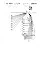
- FIG. 18is a toe end section view of a pitching wedge golf iron as seen along line 18--18 of FIG. 12;
- FIG. 19shows the views of FIGS. 16, 17, and 18 super-imposed on each other for the purposes of illustrating offset
- FIG. 21is an enlarged cross-sectional view of a parabolic groove in the striking face of the #5 golf iron shown in FIG. 17;
- FIG. 22is an enlarged cross-section view of a box groove in the striking face of a conventional golf iron
- FIG. 23is an enlarged sectional view of a V-groove in the striking face of a conventional golf iron
- FIG. 24is an enlarged cross-sectional view showing the conventional box-groove of FIG. 22 superimposed over the parabolic groove shown in FIG. 21;
- FIG. 25is a bottom plan view of a #5 golf iron of the present invention.
- FIG. 26is a schematic representation showing the sole profiles of the set of golf irons of the present invention.
- FIG. 1there is shown the head of a #5 golf iron 50 embodying the present invention.
- the #5 golf iron shown in FIG. 1is one of a set of golf irons shown in segmented elevation views in FIGS. 3-13 including a #1 golf iron 10, a #2 golf iron 20, a #3 golf iron 30, a #4 golf iron 40, the #5 golf iron 50, a #6 golf iron 60, a #7 golf iron 70, a #8 golf iron 80, a #9 golf iron 90, a pitching wedge golf iron 100, and a sand wedge golf iron 110.
- each of the golf irons shown in FIGS. 3-13are identified by a two-digit number in which the first digit identifies the iron number and the second digit identifies the feature.
- the #1 golf iron 10has a shaft 11.
- the shafts for the other golf ironsare identified as 21 for iron #2, 31 for iron #3, and so on ending with 101 identifying the shaft of the pitching wedge and 111 identifying the shaft of the sand wedge.
- the common featureswill be described in connection with the #5 golf iron shown in FIGS. 7A and 7B.
- the #5 iron 50has a head 58 with an integral hosel 53, a heel 54, a toe 55, a sole 56, and a striking face 57.
- a shaft 51is inserted into the hosel 53 and has a shaft axis 52.
- the iron head 58has a center of mass 59.
- the centers of mass 19, 29, 39, 49, 59, 69, 79, 89, 99, 109, and 119 for each iron in the setare spaced vertically by distances 271-281 above the horizontal plane 135 as set out in Table 2 below.
- the centers of massare shown projected into the vertical plane 450 (FIG. 19) which includes the axis (eg. 22, 52, or 102) of the shaft and not in the segmented and rotated plane of the iron's face. Consequently, the vertical distances 272, 275, and 280 are measured from the ground plane 135 to the heights of the centers of mass 29, 59, and 109 in the vertical plane 450 (FIG. 19).
- the offset of a golf ironis defined as the horizontal distance between the leading edge of the face of the golf iron and the axis of the shaft.
- FIGS. 16, 17, and 18,there is shown the cross-sections for the #2 iron, #5 iron, and pitching wedge iron.
- the profiles for the #2 iron, #5 iron, and pitching wedgeare superimposed on each other in FIG. 19 and are oriented so that the shaft axes 22, 52, and 102, coincide and provide a vertical reference for gauging the offset of each club.
- the three clubsrespectively have striking faces 27, 57, and 107 with leading edges 302, 305, and 310.
- each of the clubsrespectively has a center of mass 29, 59, and 109.
- the #2 iron 20has its leading edge 302 behind the vertical reference 22, 52, and 102 in the horizontal direction.
- the #2 ironis said to have a negative offset.
- the pitching wedge 100has its leading edge 310 in front of the vertical reference of the shaft axes (22, 52, 102) in the horizontal direction so that it is said to have a positive offset.
- the #5 iron 50typically has its leading edge 305 essentially in line with the vertical reference (22, 52, 102) established by the shaft axes thereby having a neutral or very close to neutral offset.
- the irons of the present inventionwhich have the loft and lie angles shown in Table 1, have an offset in accordance with the following Table 3.
- the offsets of the irons of the present invention illustrated in FIG. 19are in general conventional.
- the offset as previously notedhelps compensate for centrifugal forces because of the distance between the axis of the shaft and the center of mass of the head.
- the centrifugal force on the center of mass of the club headpulls the center of mass downward as indicated by arrow 126 in FIG. 19 for the pitching wedge 100. Consequently, the flex in the shaft 101 causes the loft angle 128 between the face 107 and the axis 102 of the shaft 101 to increase thereby imparting a greater loft and therefore less distance to the golf ball.
- a line 130which is the center line of the face on each iron, intersects the ground or horizontal plane 135 at a point 134.
- the line 130is essentially perpendicular to the leading edge of each iron and is aligned with the center of mass of each iron.
- a projection of the shaft axis 52intersects the horizontal plane 135 at a point 136.
- the distance 145 along the horizontal plane between the points 134 and 136is the displacement between the center of mass and the axis of the shaft.
- each ironhas a different displacement. Referring to FIGS.
- the #1 ironhas a displacement 141
- the #2 ironhas a displacement 142
- the #3 ironhas a displacement 143
- the #4 ironhas a displacement 144
- the #5 ironhas a displacement 145
- the #6 ironhas a displacement 146
- the #7 ironhas a displacement 147
- the #8 ironhas a displacement 148
- the #9 ironhas a displacement 149
- the pitching wedgehas a displacement 150
- the sand wedgehas a displacement 151.
- the preferred displacements for a set of irons made in accordance with the present inventionare set forth in Table 4.
- the displacements shown in Table 4result from establishing a starting reference with the #1 long iron (FIG. 3) which in one conventional embodiment has a displacement 141 of 1.5 inch and a lie angle 139 of 57° (Table 1).
- the shaft axis 12intersects line 130 at a point 137.
- the other displacements 142-151are determined at the horizontal plane 135 for each lie angle for each iron. If the lie angles are adjusted to accommodate a manufacturer's preference, the displacements should be changed accordingly.
- the rotational moment of inertiais related to the mass of the head and the perpendicular distance 162 from the shaft axis 52. It should be understood that the distance 162 shown in FIG. 7B is not a true representation because the center of mass is displaced into the plane of the drawing.
- the perpendicular distance 162is 1.5991 inch
- the mass of the head 50is 251 gms.
- the rotational moment of inertia about the shaft axis 52can be calculated for each iron by the formula: ##EQU1## where M is the mass, L is the distance 162, and B is the average thickness of the head (equal to approximately 0.4 inch for each iron).
- the golf irons shown in FIGS. 3-13, having the loft angles, the offsets, and the displacement disclosed in Tables 1, 3, and 4have the following perpendicular distances, masses, and moments of inertia shown in Table 5.
- the moments of inertia for the irons in the setare approximately equal within less than 10%. It is believed that variations of as much as 17% will still produce the benefits of the invention.
- the variationis calculated by determining the maximum difference in the moments of inertia between any of the irons in the set (except for the sand wedge) and dividing the difference by the lowest moment of inertia.
- each iron of the set of ironshas a reinforcing column behind the center of mass to reinforce the blade of the golf iron and to reduce any hollow or ringing sound that may result.
- the #5 golf iron 50which is illustrative of all of the irons in the set, has a back side 168 which has a cavity 170 formed therein.
- the cavity 170is for the purpose of distributing the majority of the mass of the golf iron at the heel 54 and the toe 55 to insure a relatively high rotational moment of inertia about the face center line 130 which passes through the center of mass 59.
- the cavityis of uniform depth centered about the center of mass.
- such a conventional ironhas a thin blade 469 (FIG. 20) behind the striking face adjacent the center of mass. Therefore, when a ball is hit with such a conventional iron, the thin blade tends to produce a hollow or ringing sound which many golfers find objectionable.
- the cavity 170which has side walls 174 and a floor surface 176.
- the floor surface 176is elevated adjacent the center of mass as the result of the presence of a segment of a support column 180 (FIG. 20).
- the column 180is positioned behind the striking face 57 (FIG. 17) and has a column axis 182 and a circumference 186.
- the axis 182is parallel to the striking face 57 and lies within a plane 184 that is perpendicular to the planar face 57 and includes the center of mass 59. As can best be seen in FIG.
- the floor surface 176 of the cavity 170is defined by the circumference 186 of the column 180 and by fill material 188 which provides a smooth transition from the circumference 186 of the column to a thin periphery 189 adjacent the sides 174.
- the support column 180 with the fill material 188provides support for the striking face at the center of mass to eliminate the hollow or ringing sound that ordinarily results from conventional golf irons which have cavities in the back side.
- the planar striking face 57 of the #5 iron shown in FIG. 7Ahas a pattern 190 of horizontal grooves 192.
- the pattern 190is configured so that the space 194 between the grooves 192 is equal for each iron in the set.
- the length 255 of the full length grooves 192a of the #5 ironoccupies a majority of the length of face 57.
- the other ironslikewise have lengths 251 to 261 for the #1 iron to the sand wedge.
- the groove lengths 251 to 261vary in direct proportion to the displacements 141-151 of the centers of mass for each iron.
- the specific length of the full length grooves 192ais not critical as long as the grooves occupy a majority of the length of the face 57.
- the length of the grooves 192ais proportional to the displacement.
- the pattern of groovesdisguises the face that the irons have the progressive displacement so that the golfer does not subconsciously compensate for the advantages that flow from the progressive displacement.
- the horizontal groove pattern 190assures that the ball when struck by the inclined face 57 takes on back spin. Back spin assures that the ball flies true and that upon landing holds the playing surface. If under wet playing conditions the horizontal grooves are not present, moisture between the ball and the striking face will cause the ball to hydroplane up the incline face 57 without taking on any substantial back spin. Consequently, the ball will fly erratically, like a knuckle ball, will fly longer than anticipated, and will not bite upon landing.
- the horizontal groovesare for the purpose of channeling away water trapped between the golf ball and the striking face 57 from the point of impact and for providing a frictional surface to assure that back spin is imparted to the ball.
- Horizontal grooves in the prior arthave been a groove 193 configured with a V cross-section as shown in FIG. 23 or a groove 195 configured with a box cross-section as shown in FIG. 22.
- Both prior art groove cross-sectionshave sharp junctions 198 and 200 where the V-shaped groove 193 intersects the striking surface 57 and junctions 202 and 204 where the box-shaped groove 195 joins the striking surface 57. Consequently, the sharp junctions 198, 200, 202, and 204 tend to scuff the ball as they impart back spin to the ball.
- FIG. 21there is shown the cross-section of one of the horizontal grooves 192 formed in accordance with the present invention.
- the groove 192 in FIG. 21has two sides 206 and 208 which join the striking face 57 at top junctions 210 and 212.
- the groovealso has a planar bottom 214 which joins the sides 206 and 208 at bottom junctions 216 and 218.
- the top junctions 210 and 212 and the major portion of the sides 206 and 208are defined by a segment of a parabola such as that comprising the parabolic spheroid 220 for side 206 and top junction 210 and parabola segment of a spheroid 222 for side 208 and top junction 212.
- One such parabolic segmentis between 220a and 220b to define the top junction 210 and the major portion of the side 206.
- the bottom junctions 216 and 218are defined by radii.
- the parabolic groove 192can direct more water away from the contact area between the ball and the striking face 57. Also, because the top junctions 210 and 212 are defined by a portion of a parabola, they are not sharp and therefore do not scuff the ball.
- the sole of each golf ironis provided with a flat spot which causes the head to sit squarely when the golf iron is grounded at address.
- the #5 iron 50 having a sole 56has a flat spot 235 on the sole measuring approximately 0.5" ⁇ 0.2". While the size of the flat spot 235 is not particularly critical, I found that the placement along the length of the sole 57 is of some importance in assisting the golfer in properly grounding the club. With reference to FIG. 26, it can be seen that the flat spot 235 on the #5 iron is located approximately half-way between the leading edge 305 and the trailing edge 325.
- the flat spots 231-241 on the irons 10, 20, 30, 40, 50, 60, 70, 80, 90, 100, and 110are progressively located between the leading edge and the trailing edge as shown in FIG. 26 in a vertical line with the centers of mass 19, 29, 39, 49, 59, 69, 79, 89, 99, 109, and 119.
Landscapes
- Health & Medical Sciences (AREA)
- General Health & Medical Sciences (AREA)
- Physical Education & Sports Medicine (AREA)
- Golf Clubs (AREA)
Abstract
Description
TABLE 1 ______________________________________ (Prior Art) Iron # Loft Angle Lie Angle ______________________________________ 1 16 57 2 18 57.5 3 21 58 4 24 59 5 27.5 60 6 32 60.5 7 37 61 8 41 61.5 9 45 62Pitching Wedge 50 63 Sand Wedge 58 63 ______________________________________
TABLE 2 ______________________________________ Center of Mass Vertical Iron # Elevation (inches) ______________________________________ 1 .798 2 .795 3 .793 4 .790 5 .787 6 .785 7 .782 8 .779 9 .776 Pitching Wedge .774 Sand Wedge .774 ______________________________________
TABLE 3 ______________________________________ Iron # Offset (Inches) ______________________________________ 1 -0.103 2 -0.082 3 -0.061 4 -0.039 5 -0.018 6 +0.003 7 +0.024 8 +0.046 9 +0.076 Pitching Wedge +0.088 Sand Wedge +0.099 ______________________________________
TABLE 4 ______________________________________ Iron # Displacement (Inches) ______________________________________ 1 1.5 2 1.4715 3 1.4433 4 1.3879 5 1.3336 6 1.3068 7 1.2804 8 1.2541 9 1.2282 Pitching Wedge 1.1769 Sand Wedge 1.1769 ______________________________________
TABLE 5 ______________________________________ Moment Perpendicular of Inertia Iron # Distance (inches) Mass (grams) (lb.ft.sec.sup.2) ______________________________________ 1 1.7221 227 4.282 × 10.sup.-4 2 1.7007 224 4.287 × 10.sup.-4 3 1.6809 239 4.296 × 10.sup.-4 4 1.6374 245 4.180 × 10.sup.-4 5 1.5991 251 4.085 × 10.sup.-4 6 1.5851 259 4.142 × 10.sup.-4 7 1.5787 265 4.204 × 10.sup.-4 8 1.5699 270 4.236 × 10.sup.-4 9 1.5600 273 4.261 × 10.sup.-4 Pitching Wedge 1.5798 279 4.432 × 10.sup.-4 Sand Wedge 1.5798 285 4.559 × 10.sup.-4 ______________________________________
Claims (9)
Priority Applications (1)
| Application Number | Priority Date | Filing Date | Title |
|---|---|---|---|
| US07/197,662US4858929A (en) | 1987-06-24 | 1988-05-13 | Golf irons |
Applications Claiming Priority (2)
| Application Number | Priority Date | Filing Date | Title |
|---|---|---|---|
| US07/066,077US4802672A (en) | 1987-06-24 | 1987-06-24 | Set of golf irons |
| US07/197,662US4858929A (en) | 1987-06-24 | 1988-05-13 | Golf irons |
Related Parent Applications (1)
| Application Number | Title | Priority Date | Filing Date |
|---|---|---|---|
| US07/066,077DivisionUS4802672A (en) | 1987-06-24 | 1987-06-24 | Set of golf irons |
Publications (1)
| Publication Number | Publication Date |
|---|---|
| US4858929Atrue US4858929A (en) | 1989-08-22 |
Family
ID=26746343
Family Applications (1)
| Application Number | Title | Priority Date | Filing Date |
|---|---|---|---|
| US07/197,662Expired - Fee RelatedUS4858929A (en) | 1987-06-24 | 1988-05-13 | Golf irons |
Country Status (1)
| Country | Link |
|---|---|
| US (1) | US4858929A (en) |
Cited By (76)
| Publication number | Priority date | Publication date | Assignee | Title |
|---|---|---|---|---|
| US5056788A (en)* | 1988-09-02 | 1991-10-15 | Maruman Golf Kabushiki Kaisha | Club set with progressively altered hosel thickness and head weight |
| USD323690S (en) | 1989-08-08 | 1992-02-04 | Wilson Sporting Goods Co. | Golf club head |
| USD323689S (en) | 1989-08-08 | 1992-02-04 | Wilson Sporting Goods Co. | Golf club head |
| US5120062A (en)* | 1990-07-26 | 1992-06-09 | Wilson Sporting Goods Co. | Golf club head with high toe and low heel weighting |
| USD327109S (en) | 1989-01-27 | 1992-06-16 | Wilson Sporting Goods Co. | Golf club head |
| US5200573A (en)* | 1991-05-28 | 1993-04-06 | Blood Charles L | Projectile having a matrix of cavities on its surface |
| US5203565A (en)* | 1992-01-22 | 1993-04-20 | Murray Tom R | Golf club head |
| US5224705A (en)* | 1990-07-26 | 1993-07-06 | Wilson Sporting Goods Co. | Golf club head with high toe and low heel weighting |
| US5228688A (en)* | 1989-03-27 | 1993-07-20 | Davis C Michael | Constant swing golf club set |
| US5290032A (en)* | 1990-04-02 | 1994-03-01 | Lisco, Inc. | Iron with progessive back cavity support bar |
| US5333872A (en)* | 1993-01-21 | 1994-08-02 | Hillerich & Bradsby Co., Inc. | Golf club irons having improved weighting |
| USD350800S (en) | 1991-10-18 | 1994-09-20 | Bost Enterprises, Inc. | Iron-type golf clubhead |
| US5378524A (en)* | 1991-05-28 | 1995-01-03 | Blood; Charles L. | Friction reducing surface and devices employing such surfaces |
| USD354786S (en) | 1993-01-21 | 1995-01-24 | Hillerich And Bradsby Co., Inc. | Golf club head |
| USD355234S (en) | 1993-06-10 | 1995-02-07 | Tommy Armour Golf Company | Golf club head |
| US5419560A (en)* | 1994-03-15 | 1995-05-30 | Bamber; Jeffrey V. | Perimeter weighted golf clubs |
| US5540437A (en)* | 1994-03-15 | 1996-07-30 | Bamber; Jeffrey V. | Perimeter weighted golf clubs |
| US5591092A (en)* | 1995-05-09 | 1997-01-07 | Acushnet Company | Golf clubs with groove configuration |
| USD387830S (en)* | 1996-08-23 | 1997-12-16 | Gilbert Peter J | Portion of a sole of a golf club head |
| US5709616A (en)* | 1996-05-31 | 1998-01-20 | Rife; Guerin D. | Groove configuration for a putter type golf club head |
| USD398355S (en) | 1995-04-04 | 1998-09-15 | Acushnet Company | Golf club head |
| USD432611S (en)* | 1999-01-28 | 2000-10-24 | Acushnet Company | Back portion of a golf club head |
| USD438272S1 (en) | 2000-03-16 | 2001-02-27 | Tad Moore | Putter head |
| JP2001161865A (en)* | 1999-11-01 | 2001-06-19 | Callaway Golf Co | Profile score line for face of golf club |
| US6290607B1 (en) | 1999-04-05 | 2001-09-18 | Acushnet Company | Set of golf clubs |
| US20020042306A1 (en)* | 2000-05-09 | 2002-04-11 | Chris Chappell | High spin golf club groove configuration |
| US6482104B1 (en) | 1999-04-05 | 2002-11-19 | Acushnet Company | Set of golf clubs |
| EP1234602A3 (en)* | 2000-12-27 | 2003-12-10 | Dunlop Slazenger Group Americas Inc | High spin golf club groove configuration |
| USD488203S1 (en) | 2003-06-16 | 2004-04-06 | Nike, Inc. | Set of a golf club heads |
| US20040087387A1 (en)* | 2002-11-01 | 2004-05-06 | Bret Wahl | Golf club head having dual-drafted grooves |
| US6835143B2 (en)* | 2000-03-07 | 2004-12-28 | The Yokohama Rubber Co., Ltd. | Method of evaluating golf club, golf club, and golf club set |
| US20060223648A1 (en)* | 2003-12-30 | 2006-10-05 | Kennedy Thomas J Iii | Golf club having stepped grooves |
| US20070149312A1 (en)* | 2004-07-30 | 2007-06-28 | Acushnet Company | Golf club head groove configuration |
| US20080032814A1 (en)* | 2006-08-07 | 2008-02-07 | Bridgestone Sports Co., Ltd. | Golf club head |
| US20080102981A1 (en)* | 2006-10-31 | 2008-05-01 | Bridgestone Sports Co., Ltd. | Golf club head |
| US20080125242A1 (en)* | 2006-11-28 | 2008-05-29 | Bridgestone Sports Co., Ltd. | Golf club head |
| US20080125243A1 (en)* | 2006-11-28 | 2008-05-29 | Bridgestone Sports Co., Ltd. | Golf club head |
| US20080132351A1 (en)* | 2006-12-01 | 2008-06-05 | Bridgestone Sports Co., Ltd. | Golf club head |
| US20080132352A1 (en)* | 2006-11-30 | 2008-06-05 | Bridgestone Sports Co., Ltd. | Golf club head |
| US20080167138A1 (en)* | 2007-01-04 | 2008-07-10 | Bridgestone Sports Co., Ltd. | Golf club head |
| US20080171613A1 (en)* | 2003-12-12 | 2008-07-17 | Acushnet Company | Golf club head groove configuration |
| US20090029797A1 (en)* | 2007-07-24 | 2009-01-29 | Bridgestone Sports Co., Ltd. | Method of manufacturing golf club head and golf club head |
| US20090036228A1 (en)* | 2007-08-02 | 2009-02-05 | Bridgestone Sports Co., Ltd. | Method of manufacturing golf club head and golf club head |
| US20090082129A1 (en)* | 2007-09-26 | 2009-03-26 | Bridgestone Sports Co., Ltd. | Method of Manufacturing Golf Club Head and Golf Club Head |
| US20090282670A1 (en)* | 2003-12-12 | 2009-11-19 | Gilbert Peter J | Golf club groove configuration |
| US20090313806A1 (en)* | 2004-07-30 | 2009-12-24 | Gilbert Peter J | Golf club groove configuration |
| US20100035702A1 (en)* | 2008-08-07 | 2010-02-11 | Solheim John A | Grooves of golf club heads and methods to manufacture grooves of golf club heads |
| US20100075772A1 (en)* | 2003-12-12 | 2010-03-25 | Gilbert Peter J | Golf club groove configuration |
| US20100093461A1 (en)* | 2008-10-13 | 2010-04-15 | Cole Eric V | Club Heads With Contoured Back Faces And Methods Of Manufacturing The Same |
| US20100093459A1 (en)* | 2008-10-13 | 2010-04-15 | Cole Eric V | Club Heads With Contoured Back Faces And Methods Of Manufacturing The Same |
| US20100190572A1 (en)* | 2003-12-12 | 2010-07-29 | Acushnet Company | Spin milled grooves for a golf club |
| USD624620S1 (en) | 2010-06-17 | 2010-09-28 | Sri Sports Limited | Golf club head |
| US20100292025A1 (en)* | 2009-05-12 | 2010-11-18 | Nelson Precision Casting Co., Ltd. | Golf club head |
| US20100311518A1 (en)* | 2009-06-03 | 2010-12-09 | Tomio Kumamoto | Golf club head |
| CN101920095A (en)* | 2009-06-10 | 2010-12-22 | 住胶体育用品株式会社 | Glof club head |
| US20110118054A1 (en)* | 2003-12-12 | 2011-05-19 | Johnson Gregory D | Golf club groove configuration |
| US7976405B2 (en) | 2003-12-12 | 2011-07-12 | Acushnet Company | Golf club groove configuration |
| US8517861B2 (en) | 2003-12-12 | 2013-08-27 | Acushnet Company | Golf club head having a grooved and textured face |
| US20130260912A1 (en)* | 2012-04-03 | 2013-10-03 | Karsten Manufacturing Corporation | Golf club heads and methods of manufacturing golf club heads |
| US9370699B1 (en) | 2015-03-31 | 2016-06-21 | Acushnet Company | Iron set groove progression |
| US9987529B2 (en) | 2012-04-03 | 2018-06-05 | Karsten Manufacturing Corporation | Golf club heads and methods of manufacturing golf club heads |
| US10423945B2 (en)* | 2016-12-31 | 2019-09-24 | Taylor Made Golf Company, Inc. | Golf club head and method of manufacture |
| US10974103B2 (en) | 2008-08-07 | 2021-04-13 | Karsten Manufacturing Corporation | Grooves of golf club heads and methods to manufacture grooves of golf club heads |
| US10974104B2 (en) | 2008-08-07 | 2021-04-13 | Karsten Manufacturing Corporation | Grooves of golf club heads and methods to manufacture grooves of golf club heads |
| US10994176B2 (en) | 2011-09-30 | 2021-05-04 | Karsten Manufacturing Corporation | Grooves of golf club heads and methods to manufacture grooves of golf club heads |
| US11083938B2 (en) | 2008-08-07 | 2021-08-10 | Karsten Manufacturing Corporation | Grooves of golf club heads and methods to manufacture grooves of golf club heads |
| USD928261S1 (en) | 2019-11-15 | 2021-08-17 | Karsten Manufacturing Corporation | Golf club head |
| US11161022B2 (en) | 2011-09-30 | 2021-11-02 | Karsten Manufacturing Corporation | Golf club heads with a multi-material striking surface |
| US20210394027A1 (en)* | 2008-10-31 | 2021-12-23 | Karsten Manufacturing Corporation | Golf club head with grooves and method of manufacture |
| US11207572B2 (en) | 2019-08-01 | 2021-12-28 | Karsten Manufacturing Corporation | Golf club heads with a multi-material striking surface |
| USRE48977E1 (en) | 2008-08-07 | 2022-03-22 | Karsten Manufacturing Corporation | Grooves of golf club heads and methods to manufacture grooves of golf club heads |
| US11420100B2 (en) | 2008-08-07 | 2022-08-23 | Karsten Manufacturing Corporation | Grooves of golf club heads and methods to manufacture grooves of golf club heads |
| US20220387862A1 (en)* | 2021-06-07 | 2022-12-08 | Sumitomo Rubber Industries, Ltd. | Golf club head |
| US11918864B2 (en) | 2019-08-01 | 2024-03-05 | Karsten Manufacturing Corporation | Golf club heads with a multi-material striking surface |
| US11992736B2 (en) | 2008-08-07 | 2024-05-28 | Karsten Manufacturing Corporation | Grooves of golf club heads and methods to manufacture grooves of golf club heads |
| USRE50247E1 (en) | 2008-08-07 | 2024-12-31 | Karsten Manufacturing Corporation | Grooves of golf club heads and methods to manufacture grooves of golf club heads |
Citations (6)
| Publication number | Priority date | Publication date | Assignee | Title |
|---|---|---|---|---|
| US1089881A (en)* | 1913-05-31 | 1914-03-10 | Thomas Taylor Jr | Golf-club. |
| US1617090A (en)* | 1925-06-08 | 1927-02-08 | George C Worthington | Golf-club head |
| US1695598A (en)* | 1928-05-15 | 1928-12-18 | Macclain Edwin Kerr | Sand wedge |
| US2332342A (en)* | 1940-03-08 | 1943-10-19 | Milton B Reach | Golf club |
| US2447967A (en)* | 1944-09-16 | 1948-08-24 | Stone William Ridgely | Golf club |
| US4529203A (en)* | 1982-09-01 | 1985-07-16 | Ribaudo Nicholas A | Golf club |
- 1988
- 1988-05-13USUS07/197,662patent/US4858929A/ennot_activeExpired - Fee Related
Patent Citations (6)
| Publication number | Priority date | Publication date | Assignee | Title |
|---|---|---|---|---|
| US1089881A (en)* | 1913-05-31 | 1914-03-10 | Thomas Taylor Jr | Golf-club. |
| US1617090A (en)* | 1925-06-08 | 1927-02-08 | George C Worthington | Golf-club head |
| US1695598A (en)* | 1928-05-15 | 1928-12-18 | Macclain Edwin Kerr | Sand wedge |
| US2332342A (en)* | 1940-03-08 | 1943-10-19 | Milton B Reach | Golf club |
| US2447967A (en)* | 1944-09-16 | 1948-08-24 | Stone William Ridgely | Golf club |
| US4529203A (en)* | 1982-09-01 | 1985-07-16 | Ribaudo Nicholas A | Golf club |
Cited By (154)
| Publication number | Priority date | Publication date | Assignee | Title |
|---|---|---|---|---|
| US5056788A (en)* | 1988-09-02 | 1991-10-15 | Maruman Golf Kabushiki Kaisha | Club set with progressively altered hosel thickness and head weight |
| USD327109S (en) | 1989-01-27 | 1992-06-16 | Wilson Sporting Goods Co. | Golf club head |
| US5228688A (en)* | 1989-03-27 | 1993-07-20 | Davis C Michael | Constant swing golf club set |
| USD323690S (en) | 1989-08-08 | 1992-02-04 | Wilson Sporting Goods Co. | Golf club head |
| USD323689S (en) | 1989-08-08 | 1992-02-04 | Wilson Sporting Goods Co. | Golf club head |
| US5290032A (en)* | 1990-04-02 | 1994-03-01 | Lisco, Inc. | Iron with progessive back cavity support bar |
| US5120062A (en)* | 1990-07-26 | 1992-06-09 | Wilson Sporting Goods Co. | Golf club head with high toe and low heel weighting |
| US5224705A (en)* | 1990-07-26 | 1993-07-06 | Wilson Sporting Goods Co. | Golf club head with high toe and low heel weighting |
| US5378524A (en)* | 1991-05-28 | 1995-01-03 | Blood; Charles L. | Friction reducing surface and devices employing such surfaces |
| US5200573A (en)* | 1991-05-28 | 1993-04-06 | Blood Charles L | Projectile having a matrix of cavities on its surface |
| USD350800S (en) | 1991-10-18 | 1994-09-20 | Bost Enterprises, Inc. | Iron-type golf clubhead |
| US5203565A (en)* | 1992-01-22 | 1993-04-20 | Murray Tom R | Golf club head |
| US5423546A (en)* | 1993-01-21 | 1995-06-13 | Hillerich & Bradsbry Co., Inc. | Golf club irons having improved weighting |
| US5333872A (en)* | 1993-01-21 | 1994-08-02 | Hillerich & Bradsby Co., Inc. | Golf club irons having improved weighting |
| USD354786S (en) | 1993-01-21 | 1995-01-24 | Hillerich And Bradsby Co., Inc. | Golf club head |
| USD355234S (en) | 1993-06-10 | 1995-02-07 | Tommy Armour Golf Company | Golf club head |
| US7128663B2 (en) | 1994-03-15 | 2006-10-31 | Pelican Golf, Inc. | Perimeter weighted golf clubs |
| US20030073511A1 (en)* | 1994-03-15 | 2003-04-17 | Bamber Jeffrey Vincent | Perimeter weighted golf clubs |
| US5669830A (en)* | 1994-03-15 | 1997-09-23 | Bamber; Jeffrey Vincent | Perimeter weighted golf clubs |
| US5827132A (en)* | 1994-03-15 | 1998-10-27 | Pelican Golf, Inc. | Perimeter weighted golf clubs |
| US5540437A (en)* | 1994-03-15 | 1996-07-30 | Bamber; Jeffrey V. | Perimeter weighted golf clubs |
| US6702693B2 (en) | 1994-03-15 | 2004-03-09 | Pelican Golf, Inc. | Perimeter weighted golf clubs |
| US7022033B2 (en) | 1994-03-15 | 2006-04-04 | Pelican Golf, Inc. | Perimeter weighted golf clubs |
| US5419560A (en)* | 1994-03-15 | 1995-05-30 | Bamber; Jeffrey V. | Perimeter weighted golf clubs |
| USD398355S (en) | 1995-04-04 | 1998-09-15 | Acushnet Company | Golf club head |
| US5591092A (en)* | 1995-05-09 | 1997-01-07 | Acushnet Company | Golf clubs with groove configuration |
| US5709616A (en)* | 1996-05-31 | 1998-01-20 | Rife; Guerin D. | Groove configuration for a putter type golf club head |
| USD387830S (en)* | 1996-08-23 | 1997-12-16 | Gilbert Peter J | Portion of a sole of a golf club head |
| USD432611S (en)* | 1999-01-28 | 2000-10-24 | Acushnet Company | Back portion of a golf club head |
| US6860819B2 (en) | 1999-04-05 | 2005-03-01 | Achushnet Company | Set of golf clubs |
| US6482104B1 (en) | 1999-04-05 | 2002-11-19 | Acushnet Company | Set of golf clubs |
| US6290607B1 (en) | 1999-04-05 | 2001-09-18 | Acushnet Company | Set of golf clubs |
| US6443856B1 (en)* | 1999-11-01 | 2002-09-03 | Callaway Golf Company | Contoured scorelines for the face of a golf club |
| JP2001161865A (en)* | 1999-11-01 | 2001-06-19 | Callaway Golf Co | Profile score line for face of golf club |
| US6835143B2 (en)* | 2000-03-07 | 2004-12-28 | The Yokohama Rubber Co., Ltd. | Method of evaluating golf club, golf club, and golf club set |
| USD438272S1 (en) | 2000-03-16 | 2001-02-27 | Tad Moore | Putter head |
| US6981923B2 (en) | 2000-05-09 | 2006-01-03 | Dunlop Sports | High spin golf club groove configuration |
| US20060003851A1 (en)* | 2000-05-09 | 2006-01-05 | Chris Chappell | High spin golf club groove configuration |
| US7258627B2 (en)* | 2000-05-09 | 2007-08-21 | Taylormade-Adidas Golf Company | High spin golf club groove configuration |
| US20020042306A1 (en)* | 2000-05-09 | 2002-04-11 | Chris Chappell | High spin golf club groove configuration |
| EP1234602A3 (en)* | 2000-12-27 | 2003-12-10 | Dunlop Slazenger Group Americas Inc | High spin golf club groove configuration |
| US6814673B2 (en) | 2002-11-01 | 2004-11-09 | Taylor Made Golf Company, Inc. | Golf club head having improved grooves |
| USRE40874E1 (en)* | 2002-11-01 | 2009-08-18 | Taylor Made Golf Company, Inc. | Golf club head having improved grooves |
| US20050085315A1 (en)* | 2002-11-01 | 2005-04-21 | Taylor Made Golf Company, Inc. | Golf club head having improved grooves |
| US7156751B2 (en) | 2002-11-01 | 2007-01-02 | Taylor Made Golf Company, Inc. | Golf club head having improved grooves |
| US20040087387A1 (en)* | 2002-11-01 | 2004-05-06 | Bret Wahl | Golf club head having dual-drafted grooves |
| USD514640S1 (en) | 2003-06-16 | 2006-02-07 | Nike, Inc. | Portion of a golf club head |
| USD515162S1 (en) | 2003-06-16 | 2006-02-14 | Nike, Inc. | Portion of a golf club head |
| USD515163S1 (en) | 2003-06-16 | 2006-02-14 | Nike, Inc. | Portion of a golf club head |
| USD515161S1 (en) | 2003-06-16 | 2006-02-14 | Nike, Inc. | Portion of a golf club head |
| USD514641S1 (en) | 2003-06-16 | 2006-02-07 | Nike, Inc. | Portion of a golf club head |
| USD514642S1 (en) | 2003-06-16 | 2006-02-07 | Nike, Inc. | Portion of a golf club head |
| USD488203S1 (en) | 2003-06-16 | 2004-04-06 | Nike, Inc. | Set of a golf club heads |
| US20100075772A1 (en)* | 2003-12-12 | 2010-03-25 | Gilbert Peter J | Golf club groove configuration |
| US8678947B2 (en) | 2003-12-12 | 2014-03-25 | Acushnet Company | Golf club groove configuration |
| US7862450B2 (en) | 2003-12-12 | 2011-01-04 | Acushnet Company | Golf club head groove configuration |
| US7976405B2 (en) | 2003-12-12 | 2011-07-12 | Acushnet Company | Golf club groove configuration |
| US20110118054A1 (en)* | 2003-12-12 | 2011-05-19 | Johnson Gregory D | Golf club groove configuration |
| US9522312B2 (en) | 2003-12-12 | 2016-12-20 | Acushnet Company | Golf club groove configuration |
| US9403068B2 (en) | 2003-12-12 | 2016-08-02 | Acushnet Company | Golf club head having a grooved and textured face |
| US9216329B2 (en) | 2003-12-12 | 2015-12-22 | Acushnet Company | Golf club groove configuration |
| US7955189B2 (en) | 2003-12-12 | 2011-06-07 | Acushnet Company | Spin milled grooves for a golf club |
| US20090282670A1 (en)* | 2003-12-12 | 2009-11-19 | Gilbert Peter J | Golf club groove configuration |
| US8517861B2 (en) | 2003-12-12 | 2013-08-27 | Acushnet Company | Golf club head having a grooved and textured face |
| US20080171613A1 (en)* | 2003-12-12 | 2008-07-17 | Acushnet Company | Golf club head groove configuration |
| US8240021B2 (en) | 2003-12-12 | 2012-08-14 | Acushnet Company | Golf club groove configuration |
| US8210966B2 (en) | 2003-12-12 | 2012-07-03 | Acushnet Company | Golf club groove configuration |
| US8128512B2 (en) | 2003-12-12 | 2012-03-06 | Acushnet Company | Golf club groove configuration |
| US20100190572A1 (en)* | 2003-12-12 | 2010-07-29 | Acushnet Company | Spin milled grooves for a golf club |
| US20060223648A1 (en)* | 2003-12-30 | 2006-10-05 | Kennedy Thomas J Iii | Golf club having stepped grooves |
| US7179175B2 (en) | 2003-12-30 | 2007-02-20 | Callaway Golf Company | Golf club having stepped grooves |
| US7568983B2 (en)* | 2004-07-30 | 2009-08-04 | Acushnet Company | Golf club head groove configuration |
| US8752271B2 (en) | 2004-07-30 | 2014-06-17 | Acushnet Company | Golf club groove configuration |
| US20090313806A1 (en)* | 2004-07-30 | 2009-12-24 | Gilbert Peter J | Golf club groove configuration |
| US20070149312A1 (en)* | 2004-07-30 | 2007-06-28 | Acushnet Company | Golf club head groove configuration |
| GB2440799A (en)* | 2006-08-07 | 2008-02-13 | Bridgestone Sports Co Ltd | Golf club head with grooves for improved backspin and reduced scuffing |
| US20080032814A1 (en)* | 2006-08-07 | 2008-02-07 | Bridgestone Sports Co., Ltd. | Golf club head |
| US20080102981A1 (en)* | 2006-10-31 | 2008-05-01 | Bridgestone Sports Co., Ltd. | Golf club head |
| US7798917B2 (en)* | 2006-10-31 | 2010-09-21 | Bridgestone Sports Co., Ltd. | Golf club head |
| US7674188B2 (en) | 2006-11-28 | 2010-03-09 | Bridgestone Sports Co, Ltd. | Golf club head |
| US20080125243A1 (en)* | 2006-11-28 | 2008-05-29 | Bridgestone Sports Co., Ltd. | Golf club head |
| US20080125242A1 (en)* | 2006-11-28 | 2008-05-29 | Bridgestone Sports Co., Ltd. | Golf club head |
| GB2444376A (en)* | 2006-11-28 | 2008-06-04 | Bridgestone Sports Co Ltd | Golf club head |
| US7594863B2 (en) | 2006-11-28 | 2009-09-29 | Bridgestone Sports Co., Ltd. | Golf club head |
| US20090312116A1 (en)* | 2006-11-28 | 2009-12-17 | Bridgestone Sports Co., Ltd. | Golf club head |
| US7846040B2 (en) | 2006-11-28 | 2010-12-07 | Bridgestone Sports Co., Ltd. | Golf club head |
| US7828671B2 (en) | 2006-11-28 | 2010-11-09 | Bridgestone Sports Co., Ltd. | Golf club head |
| US20080132352A1 (en)* | 2006-11-30 | 2008-06-05 | Bridgestone Sports Co., Ltd. | Golf club head |
| US7677990B2 (en) | 2006-11-30 | 2010-03-16 | Bridgestone Sports Co., Ltd. | Golf club head |
| US7815521B2 (en) | 2006-12-01 | 2010-10-19 | Bridgestone Sports, Co., Ltd. | Golf club head |
| US20080132351A1 (en)* | 2006-12-01 | 2008-06-05 | Bridgestone Sports Co., Ltd. | Golf club head |
| US7691007B2 (en) | 2007-01-04 | 2010-04-06 | Bridgestone Sports Co., Ltd. | Golf club head |
| US20080167138A1 (en)* | 2007-01-04 | 2008-07-10 | Bridgestone Sports Co., Ltd. | Golf club head |
| US20090029797A1 (en)* | 2007-07-24 | 2009-01-29 | Bridgestone Sports Co., Ltd. | Method of manufacturing golf club head and golf club head |
| US7798918B2 (en) | 2007-07-24 | 2010-09-21 | Bridgestone Sports Co., Ltd. | Method of manufacturing golf club head and golf club head |
| US20090036228A1 (en)* | 2007-08-02 | 2009-02-05 | Bridgestone Sports Co., Ltd. | Method of manufacturing golf club head and golf club head |
| US20090082129A1 (en)* | 2007-09-26 | 2009-03-26 | Bridgestone Sports Co., Ltd. | Method of Manufacturing Golf Club Head and Golf Club Head |
| USRE50231E1 (en) | 2008-08-07 | 2024-12-10 | Karsten Manufacturing Corporation | Grooves of golf club heads and methods to manufacture grooves of golf club heads |
| USRE50247E1 (en) | 2008-08-07 | 2024-12-31 | Karsten Manufacturing Corporation | Grooves of golf club heads and methods to manufacture grooves of golf club heads |
| US11957962B2 (en) | 2008-08-07 | 2024-04-16 | Karsten Manufacturing Corporation | Grooves of golf club heads and methods to manufacture grooves of golf club heads |
| US8066586B2 (en)* | 2008-08-07 | 2011-11-29 | Karsten Manufacturing Corporation | Grooves of golf club heads and methods to manufacture grooves of golf club heads |
| USRE49856E1 (en) | 2008-08-07 | 2024-03-05 | Karsten Manufacturing Corporation | Grooves of golf club heads and methods to manufacture grooves of golf club heads |
| US20100035702A1 (en)* | 2008-08-07 | 2010-02-11 | Solheim John A | Grooves of golf club heads and methods to manufacture grooves of golf club heads |
| US10974103B2 (en) | 2008-08-07 | 2021-04-13 | Karsten Manufacturing Corporation | Grooves of golf club heads and methods to manufacture grooves of golf club heads |
| US11420100B2 (en) | 2008-08-07 | 2022-08-23 | Karsten Manufacturing Corporation | Grooves of golf club heads and methods to manufacture grooves of golf club heads |
| US10974104B2 (en) | 2008-08-07 | 2021-04-13 | Karsten Manufacturing Corporation | Grooves of golf club heads and methods to manufacture grooves of golf club heads |
| US11992736B2 (en) | 2008-08-07 | 2024-05-28 | Karsten Manufacturing Corporation | Grooves of golf club heads and methods to manufacture grooves of golf club heads |
| USRE49857E1 (en) | 2008-08-07 | 2024-03-05 | Karsten Manufacturing Corporation | Grooves of golf club heads and methods to manufacture grooves of golf club heads |
| US11083938B2 (en) | 2008-08-07 | 2021-08-10 | Karsten Manufacturing Corporation | Grooves of golf club heads and methods to manufacture grooves of golf club heads |
| USRE48977E1 (en) | 2008-08-07 | 2022-03-22 | Karsten Manufacturing Corporation | Grooves of golf club heads and methods to manufacture grooves of golf club heads |
| US11141634B2 (en) | 2008-08-07 | 2021-10-12 | Karsten Manufacturing Corporation | Grooves of golf club heads and methods to manufacture grooves of golf club heads |
| US11559726B2 (en) | 2008-08-07 | 2023-01-24 | Karsten Manufacturing Company | Grooves of golf club heads and methods to manufacture grooves of golf club heads |
| US12220618B2 (en) | 2008-08-07 | 2025-02-11 | Karsten Manufacturing Corporation | Grooves of golf club heads and methods to manufacture grooves of golf club heads |
| US8221264B2 (en) | 2008-10-13 | 2012-07-17 | Karsten Manufacturing Corporation | Club heads with contoured back faces and methods of manufacturing the same |
| US7914394B2 (en)* | 2008-10-13 | 2011-03-29 | Karsten Manufacturing Corporation | Club heads with contoured back faces and methods of manufacturing the same |
| US7794335B2 (en)* | 2008-10-13 | 2010-09-14 | Karsten Manufacturing Corporation | Club heads with contoured back faces and methods of manufacturing the same |
| US20100279790A1 (en)* | 2008-10-13 | 2010-11-04 | Karsten Manufacturing Corporation | Club Heads With Contoured Back Faces And Methos Of Manufacturing The Same |
| US20100093459A1 (en)* | 2008-10-13 | 2010-04-15 | Cole Eric V | Club Heads With Contoured Back Faces And Methods Of Manufacturing The Same |
| US8616998B2 (en) | 2008-10-13 | 2013-12-31 | Karsten Manufacturing Corporation | Club heads with contoured back faces and methods of manufacturing the same |
| US20100093461A1 (en)* | 2008-10-13 | 2010-04-15 | Cole Eric V | Club Heads With Contoured Back Faces And Methods Of Manufacturing The Same |
| US20110118055A1 (en)* | 2008-10-13 | 2011-05-19 | Cole Eric V | Club heads with contoured back faces and methods of manufacturing the same |
| US8235842B2 (en)* | 2008-10-13 | 2012-08-07 | Karsten Manufacturing Corporation | Club heads with contoured back faces and methods of manufacturing the same |
| US20210394027A1 (en)* | 2008-10-31 | 2021-12-23 | Karsten Manufacturing Corporation | Golf club head with grooves and method of manufacture |
| US11857850B2 (en)* | 2008-10-31 | 2024-01-02 | Karsten Manufacturing Corporation | Golf club head with grooves and method of manufacture |
| US20100292025A1 (en)* | 2009-05-12 | 2010-11-18 | Nelson Precision Casting Co., Ltd. | Golf club head |
| US8029384B2 (en)* | 2009-05-12 | 2011-10-04 | Fusheng Precision Co., Ltd. | Golf club head |
| US20100311518A1 (en)* | 2009-06-03 | 2010-12-09 | Tomio Kumamoto | Golf club head |
| US8444503B2 (en)* | 2009-06-03 | 2013-05-21 | Sri Sports Limited | Golf club head |
| CN101920095A (en)* | 2009-06-10 | 2010-12-22 | 住胶体育用品株式会社 | Glof club head |
| CN101920095B (en)* | 2009-06-10 | 2011-12-14 | 住胶体育用品株式会社 | Golf club head |
| USD624620S1 (en) | 2010-06-17 | 2010-09-28 | Sri Sports Limited | Golf club head |
| US10994176B2 (en) | 2011-09-30 | 2021-05-04 | Karsten Manufacturing Corporation | Grooves of golf club heads and methods to manufacture grooves of golf club heads |
| US12138513B2 (en) | 2011-09-30 | 2024-11-12 | Karsten Manufacturing Corporation | Golf club heads with a multi-material striking surface |
| US11161022B2 (en) | 2011-09-30 | 2021-11-02 | Karsten Manufacturing Corporation | Golf club heads with a multi-material striking surface |
| US9050509B2 (en)* | 2012-04-03 | 2015-06-09 | Karsten Manufacturing Corporation | Golf club heads and methods of manufacturing golf club heads |
| US9504888B2 (en)* | 2012-04-03 | 2016-11-29 | Karsten Manufacturing Corporation | Golf club heads and methods of manufacturing golf club heads |
| US20150258392A1 (en)* | 2012-04-03 | 2015-09-17 | Karsten Manufacturing Corporation | Golf club heads and methods of manufacturing golf club heads |
| US10434382B2 (en) | 2012-04-03 | 2019-10-08 | Karsten Manufacturing Corporation | Golf club heads and methods of manufacturing golf club heads |
| US10960276B2 (en) | 2012-04-03 | 2021-03-30 | Karsten Manufacturing Corporation | Golf club heads and methods of manufacturing golf club heads |
| US20130260912A1 (en)* | 2012-04-03 | 2013-10-03 | Karsten Manufacturing Corporation | Golf club heads and methods of manufacturing golf club heads |
| US9987529B2 (en) | 2012-04-03 | 2018-06-05 | Karsten Manufacturing Corporation | Golf club heads and methods of manufacturing golf club heads |
| US9808684B2 (en) | 2015-03-31 | 2017-11-07 | Acushnet Company | Iron set groove progression |
| US9370699B1 (en) | 2015-03-31 | 2016-06-21 | Acushnet Company | Iron set groove progression |
| US11164171B2 (en)* | 2016-12-31 | 2021-11-02 | Taylor Made Golf Company, Inc. | Golf club head and method of manufacture |
| US11907923B2 (en) | 2016-12-31 | 2024-02-20 | Taylor Made Golf Company, Inc. | Golf club head and method of manufacture |
| US11004046B2 (en)* | 2016-12-31 | 2021-05-11 | Taylor Made Golf Company, Inc. | Golf club head and method of manufacture |
| US10423945B2 (en)* | 2016-12-31 | 2019-09-24 | Taylor Made Golf Company, Inc. | Golf club head and method of manufacture |
| US11918864B2 (en) | 2019-08-01 | 2024-03-05 | Karsten Manufacturing Corporation | Golf club heads with a multi-material striking surface |
| US11207572B2 (en) | 2019-08-01 | 2021-12-28 | Karsten Manufacturing Corporation | Golf club heads with a multi-material striking surface |
| US12280301B2 (en) | 2019-08-01 | 2025-04-22 | Karsten Manufacturing Corporation | Golf club heads with a multi-material striking surface |
| US12370417B2 (en) | 2019-08-01 | 2025-07-29 | Karsten Manufacturing Corporation | Golf club heads with a multi-material striking surface |
| USD928261S1 (en) | 2019-11-15 | 2021-08-17 | Karsten Manufacturing Corporation | Golf club head |
| US11951364B2 (en)* | 2021-06-07 | 2024-04-09 | Sumitomo Rubber Industries, Ltd. | Golf club head |
| US20220387862A1 (en)* | 2021-06-07 | 2022-12-08 | Sumitomo Rubber Industries, Ltd. | Golf club head |
Similar Documents
| Publication | Publication Date | Title |
|---|---|---|
| US4858929A (en) | Golf irons | |
| US4957294A (en) | Golf club head | |
| US4802672A (en) | Set of golf irons | |
| US4854581A (en) | Golf irons | |
| US5333872A (en) | Golf club irons having improved weighting | |
| US5658209A (en) | Golf club head with optimum distributed mass contour | |
| US5335914A (en) | Golf club head | |
| US4944515A (en) | Hollow golf club head with internal support | |
| US4498673A (en) | Golf club | |
| US4913435A (en) | Golf club and a set of golf clubs | |
| US4762322A (en) | Golf club | |
| US5326105A (en) | Sea plane sole for a golf club | |
| US5547426A (en) | Progressive golf club having a diagonally balanced slot back | |
| US5356138A (en) | Dual weight golf club set | |
| US5544884A (en) | Golf club with skewed sole | |
| US5120062A (en) | Golf club head with high toe and low heel weighting | |
| US3655188A (en) | Correlated golf club set | |
| US5209473A (en) | Set of golf clubs having oval shape cavity back | |
| JPH0456629B2 (en) | ||
| GB2117254A (en) | Golf clubs | |
| JPH0639060A (en) | Improvement of golf club head | |
| US5224705A (en) | Golf club head with high toe and low heel weighting | |
| JPH06327798A (en) | Balanced golf putter | |
| US5501460A (en) | Golf club set with constant projected topline angle | |
| JPS6031740Y2 (en) | iron club set |
Legal Events
| Date | Code | Title | Description |
|---|---|---|---|
| FEPP | Fee payment procedure | Free format text:PAYOR NUMBER ASSIGNED (ORIGINAL EVENT CODE: ASPN); ENTITY STATUS OF PATENT OWNER: LARGE ENTITY | |
| FPAY | Fee payment | Year of fee payment:4 | |
| FPAY | Fee payment | Year of fee payment:8 | |
| AS | Assignment | Owner name:MGC HOLDING INC., A CORP OF DELAWARE, GEORGIA Free format text:ASSIGNMENT OF ASSIGNORS INTEREST;ASSIGNOR:MACGREGOR GOLF COMPANY;REEL/FRAME:008568/0522 Effective date:19970131 | |
| AS | Assignment | Owner name:MACGREGOR GOLF COMPANY, GEORGIA Free format text:CHANGE OF NAME;ASSIGNOR:MGC HOLDING INC.;REEL/FRAME:008545/0939 Effective date:19970204 | |
| AS | Assignment | Owner name:CONGRESS FINANCIAL CORPORATION (WESTERN), CALIFORN Free format text:SECURITY AGREEMENT;ASSIGNOR:MACGREGOR GOLF COMPANY;REEL/FRAME:009845/0782 Effective date:19990319 | |
| REMI | Maintenance fee reminder mailed | ||
| LAPS | Lapse for failure to pay maintenance fees | ||
| FP | Lapsed due to failure to pay maintenance fee | Effective date:20010822 | |
| AS | Assignment | Owner name:MACGREGOR GOLF COMPANY, GEORGIA Free format text:NOTICE OF RELEASE OF SECURITY INTEREST IN PATENTS;ASSIGNOR:CONGRESS FINANCIAL CORPORATION (WESTERN);REEL/FRAME:012973/0547 Effective date:20020530 | |
| AS | Assignment | Owner name:FOOTHILL CAPITAL CORPORATION, GEORGIA Free format text:SECURITY INTEREST;ASSIGNOR:MACGREGOR GOLF COMPANY;REEL/FRAME:013077/0244 Effective date:20020701 | |
| STCH | Information on status: patent discontinuation | Free format text:PATENT EXPIRED DUE TO NONPAYMENT OF MAINTENANCE FEES UNDER 37 CFR 1.362 |