US4858790A - Collapsible chamber metering valve - Google Patents
Collapsible chamber metering valveDownload PDFInfo
- Publication number
- US4858790A US4858790AUS07/236,398US23639888AUS4858790AUS 4858790 AUS4858790 AUS 4858790AUS 23639888 AUS23639888 AUS 23639888AUS 4858790 AUS4858790 AUS 4858790A
- Authority
- US
- United States
- Prior art keywords
- valve
- sleeve
- chamber
- stem
- internal chamber
- Prior art date
- Legal status (The legal status is an assumption and is not a legal conclusion. Google has not performed a legal analysis and makes no representation as to the accuracy of the status listed.)
- Expired - Lifetime
Links
- 239000012530fluidSubstances0.000claimsabstractdescription20
- 239000000463materialSubstances0.000claimsabstractdescription5
- 238000007789sealingMethods0.000claimsdescription6
- 238000004891communicationMethods0.000claimsdescription3
- 230000000994depressogenic effectEffects0.000description3
- 238000000465mouldingMethods0.000description2
- 125000006850spacer groupChemical group0.000description2
- 230000006835compressionEffects0.000description1
- 238000007906compressionMethods0.000description1
- 238000011109contaminationMethods0.000description1
- 230000006866deteriorationEffects0.000description1
- 239000013536elastomeric materialSubstances0.000description1
- 230000003993interactionEffects0.000description1
- 238000002955isolationMethods0.000description1
- 238000004519manufacturing processMethods0.000description1
- 229940126601medicinal productDrugs0.000description1
- 238000000034methodMethods0.000description1
- 229920003052natural elastomerPolymers0.000description1
- 229920001194natural rubberPolymers0.000description1
- 230000035515penetrationEffects0.000description1
- 239000004033plasticSubstances0.000description1
- 229920003023plasticPolymers0.000description1
- 230000037452primingEffects0.000description1
- 230000003068static effectEffects0.000description1
- 229920003051synthetic elastomerPolymers0.000description1
- 239000005061synthetic rubberSubstances0.000description1
- 229920002725thermoplastic elastomerPolymers0.000description1
- 230000008719thickeningEffects0.000description1
Images

Classifications
- F—MECHANICAL ENGINEERING; LIGHTING; HEATING; WEAPONS; BLASTING
- F16—ENGINEERING ELEMENTS AND UNITS; GENERAL MEASURES FOR PRODUCING AND MAINTAINING EFFECTIVE FUNCTIONING OF MACHINES OR INSTALLATIONS; THERMAL INSULATION IN GENERAL
- F16K—VALVES; TAPS; COCKS; ACTUATING-FLOATS; DEVICES FOR VENTING OR AERATING
- F16K17/00—Safety valves; Equalising valves, e.g. pressure relief valves
- F16K17/02—Safety valves; Equalising valves, e.g. pressure relief valves opening on surplus pressure on one side; closing on insufficient pressure on one side
- F16K17/04—Safety valves; Equalising valves, e.g. pressure relief valves opening on surplus pressure on one side; closing on insufficient pressure on one side spring-loaded
- B—PERFORMING OPERATIONS; TRANSPORTING
- B65—CONVEYING; PACKING; STORING; HANDLING THIN OR FILAMENTARY MATERIAL
- B65D—CONTAINERS FOR STORAGE OR TRANSPORT OF ARTICLES OR MATERIALS, e.g. BAGS, BARRELS, BOTTLES, BOXES, CANS, CARTONS, CRATES, DRUMS, JARS, TANKS, HOPPERS, FORWARDING CONTAINERS; ACCESSORIES, CLOSURES, OR FITTINGS THEREFOR; PACKAGING ELEMENTS; PACKAGES
- B65D83/00—Containers or packages with special means for dispensing contents
- B65D83/14—Containers for dispensing liquid or semi-liquid contents by internal gaseous pressure, i.e. aerosol containers comprising propellant
- B65D83/44—Valves specially adapted for the discharge of contents; Regulating devices
- B65D83/52—Metering valves; Metering devices
Definitions
- This inventionrelates to collapsible chamber metering valves of the type in which an elastomeric sleeve overlays a valve body to define a collapsible chamber therebetween.
- valves of this typeA problem exists with existing valves of this type in that the complex shapes of valve components required presents difficulties in moulding from plastics materials and also the number of components involved requires complex assembley procedures. Consequently such valves have been uneconomic to produce.
- a collapsible chamber metering valvefor use in a pressurised dispensing container comprising a generally cylindrical body, an elastomeric sleeve coaxially overlaying the body and defining a collapsible chamber therebetween, the body defining an internal chamber, channel means providing a fluid flowpath between the internal chamber and the collapsible chamber, an axially slidable valve actuating stem extending coaxially through the internal chamber, outlet valve means operable between the stem and the body at the outer end of the internal chamber so as to dispense fluid therefrom in an open condition of the valve and inlet valve means operable between the sleeve and the stem at the inner end of the collapsible chamber to admit fluid thereto in a closed condition of the valve, wherein the inlet valve means comprises an annular seal portion of the sleeve co-operating with an inner end portion of the stem extending therethrough and wherein the sleeve further comprises an annular shoulder portion integral
- An advantage of such an arrangementis that the sleeve and the seal portion are integrally formed thereby reducing the number of components.
- the flexibility of the seal portionallows manufacturing tolerances to be relaxed with respect to the relative positions of the stem and the seal portion.
- a further advantageis that the rigidity of the shoulder portion and the manner in which it is positively located in a static position on the body results in a high degree of isolation being achieved between the flexible seal portion and the relatively flexible sidewalls of the sleeve which define the collapsible chamber.
- the sidewalls, the shoulder portion and the seal portionmay therefore be integrally formed without the disadvantage of interaction in the operation of the inlet valve means and the collapsible chamber.
- the sleeveis readily mouldable in a single simple operation.
- the sealfurther comprises a radially outwardly extending annular flange at its outer axial extremity, which flange provides sealing gasket means in use between a similarly extending flange of the body and a rim of the container.
- An advantage of such an arrangementis that the need for a separate gasket component is obviated.
- This arrangementalso simplifies assembly because the sleeve, the body and the container rim may be nestably located and connected together by the addition of a crimped valve ferrule to form a fluid tight seal between the body and the container rim.
- the channel meanscomprises a slot in the body extending axially from the inner end of the body into communication with the collapsible chamber, at least the inner end portion of the slot extending radially into the internal chamber to provide a flowpath between the collapsible chamber and a location in the internal chamber adjacent to the inlet valve means.
- An advantage of such a slotis that the flowpath provided enables the collapsible chamber to be refilled with fluid passing through the inlet valve means directly into the collapsible chamber via the slot when the valve is in the closed condition.
- This arrangementis distinguished from prior art arrangements in which the refill flowpath takes an indirect path from the inlet valve means, along the length of the internal chamber and then through an access port into the collapsible chamber.
- the present inventionthereby provides faster refilling of the collapsible chamber.
- the slotis readily moulded as a feature of the body since it does not require the use of radially moving moulding tools.
- the seal portion of the sleevecomprises a tubular projection having a radially inwardly directed annular rib of part circular cross section.
- An advantage of such a ribis that friction between the seal portion and the stem is reduced to thereby providing smoothness of operation.
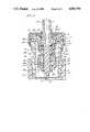
- FIG. 1is a sectional elevation of a collapsible chamber metering valve in the closed condition and;
- FIG. 2is a similar view of the valve of FIG. 1 in the open condition.
- the valve 1 of FIG. 1is shown in combination with a pressurised dispensing container 2 having a cylindrical container body 3.
- the valve 1is held in place on a rim 4 of the container body 3 by means of a crimped valve ferrule 5.
- a valve stem 6has an outer end 7 which projects from the valve 1 in an outward direction with respect to the container body 3 and has an inner end portion 8 projecting from the valve 1 in an inward direction with respect to the container 2, the valve 1 having a generally cylindrical body 9 defining an axis of symmetry 10 along which the stem 6 is reciprocatingly slidable.
- the valve body 9has an external surface 11 which is stepped in diameter so as to progressively decrease in size in the inward axial direction with respect to the container 2.
- An annular shoulder portion 16 of the sleeve 12is formed by a thickening of the sleeve material at the inner end 17 of the sidewall 38 such that the shoulder portion extends radially inwardly with respect to the axis 10 into contact with the inner end 15 of the body. Because of the stepped taper of the external surface 11, an annular chamber 14 is defined between the sleeve 12 and the external surface intermediate the outer end 13 and the inner end 15 of the body. The shoulder portion 16 is contoured to nestably receive the inner end 15 of the body and in this way the sleeve 12 is positively located in coaxial alignment with the body 9.
- the annular chamber 14is thereby closed at its innermost end with respect to the container 2 by the annular shoulder 16.
- An internal chamber 18is defined within the body 9 and extends axially from an outlet aperture 19 through which the outer end 7 of the stem extends and an inlet aperture 20 through which the inner end portion 8 of the stem extends.
- An outlet valve means 33is formed in the outlet aperture 19 by a radially outwardly projecting annular flange 22 of the stem 6 co-operating with an annular elastomeric seal 23 which is held in sealing contact with the body 9 by the valve ferrule 5.
- a radially extending bore 24 of the stemcommunicates with an axially extending outlet channel 25 within the stem, the bore 24 being disposed outside of the internal chamber 18 in the closed condition of valve 1 as shown in FIG. 1 in which the position of the stem is such that the bore is overlaid by the seal 23.
- the seal 23not only prevents leakage of fluid from the internal chamber 18 around the stem 6 but also prevents the bore 24 from communicating directly with the atmosphere. This prevents any deterioration of product fluid trapped in the stem 6 when the apparatus is not in use and also prevents leakage or drain back from the stem on to the exterior of the ferrule 5.
- the stem 6is biassed outwardly by a helical spring 26 held in compression between the stem flange 22 and a shoulder 27 formed in the internal chamber 18.
- An inlet valve means 21comprises a tubular extension 28 of the sleeve 12 having a radially inwardly projecting rib 29 which is dimensioned to provide a sealing fit around the stem 6.
- the inner end portion 8 of the stem 6is reduced in diameter such that an annular opening 30 is formed between the stem 6 and the rib 29 (and therefore the inlet valve means 21 is in an open condition) when the valve 1 is in a closed condition as shown in FIG. 1.
- An axially extending slot 31is formed in the inner end 15 of the body 9 and the slot extends axially to a greater extent than the annular shoulder portion 16 of the sleeve so as to communicate with the annular chamber 14.
- the slot 31has an inner end portion 32 which extends radially into communication with the internal chamber 18 at a location which is adjacent to the inlet valve means 21.
- the internal chamber 18is of reduced diameter at this location but axially extending spacer ribs 34 are provided within the internal chamber 18 and project radially inwardly to maintain clearance between the stem 6 and the internal chamber walls. The spacer ribs 34 also serve to maintain the stem 6 in alignment with the axis 10.
- the sleeve 12has at its outer end 35 a radially outwardly extending annular flange 36 which serves as a gasket means between a radially outwardly extending flange 37 of the body 9 and the rim 4 of the container 2.
- the cylindrical sidewall 38 of the sleeve 12extends between the flange 36 and the shoulder portion 16.
- the flange 36, the sidewall 38, the shoulder 16 and the extension 28 including the rib 29are all integrally formed of an elastomeric material which may be a natural or synthetic rubber or may be a thermoplastic elastomer.
- the radial thickness of the shoulder 16is 1.4 millimeters compared with the much thinner thickness on the extension 28 which is 0.5 millimeters.
- the shoulder 16is relatively rigid whereas the extension 28 is relatively flexible.
- the rib 29projects radially inwardly by 0.54 millimeters from the extension 28.
- the radial thickness of the sidewall 38is 0.55 millimetre so that the sidewall is relatively flexible. This flexibility allows the annular chamber 14 to be collapsible by radially inward deformation of the sidewall 38.
- the rib 29is of semi circular cross section and in its relaxed state has an internal diameter which is slightly less than the diameter of the stem 6 but greater than the diameter of the inner end portion 8.
- FIG. 2.shows the valve in the open condition in which the stem 6 is depressed inwardly with respect to the container 2 such that the bore 24 communicates with the internal chamber 18 to thereby open the outlet valve means 33.
- the depressed stem 6makes sealing contact with the rib 29 of the extension 28 such that the inlet valve means 21 is in a closed condition. Penetration of the stem through the rib 29 is accommodated by resilient deformation of the extension 28.
- the container body 3In use the container body 3 is charged with a pressurised fluid to be dispensed and once the valve 1 has been primed by an initial priming stroke of the valve stem the internal chamber -8 and the annular chamber 14 become filled with fluid.
- the seal 23 of the outlet valve means 33comprises a double seat arrangement (not shown) in which two axially spaced valve seats are integrally formed in a sealing component. Such an arrangement provides additional protection against external contamination of the product.
- the valvehas application in pressurised dispensing containers which are required to operate at any orientation since the metered quantity dispensed is independent of valve orientation.
- the valvetherefore has particular application to dispensers for nasal administration of medicinal products.
Landscapes
- Engineering & Computer Science (AREA)
- Mechanical Engineering (AREA)
- Chemical & Material Sciences (AREA)
- Dispersion Chemistry (AREA)
- General Engineering & Computer Science (AREA)
- Containers And Packaging Bodies Having A Special Means To Remove Contents (AREA)
- Self-Closing Valves And Venting Or Aerating Valves (AREA)
- Closures For Containers (AREA)
- Measuring Volume Flow (AREA)
Abstract
Description
This invention relates to collapsible chamber metering valves of the type in which an elastomeric sleeve overlays a valve body to define a collapsible chamber therebetween.
A problem exists with existing valves of this type in that the complex shapes of valve components required presents difficulties in moulding from plastics materials and also the number of components involved requires complex assembley procedures. Consequently such valves have been uneconomic to produce.
According to the present invention there is disclosed a collapsible chamber metering valve for use in a pressurised dispensing container comprising a generally cylindrical body, an elastomeric sleeve coaxially overlaying the body and defining a collapsible chamber therebetween, the body defining an internal chamber, channel means providing a fluid flowpath between the internal chamber and the collapsible chamber, an axially slidable valve actuating stem extending coaxially through the internal chamber, outlet valve means operable between the stem and the body at the outer end of the internal chamber so as to dispense fluid therefrom in an open condition of the valve and inlet valve means operable between the sleeve and the stem at the inner end of the collapsible chamber to admit fluid thereto in a closed condition of the valve, wherein the inlet valve means comprises an annular seal portion of the sleeve co-operating with an inner end portion of the stem extending therethrough and wherein the sleeve further comprises an annular shoulder portion integrally formed of relatively thick and thin material respectively whereby the shoulder portion and seal portion are relatively rigid and flexible respectively so as to positively locate the sleeve upon the valve body whilst permitting deformation of the seal portion.
(The terms inner and outer unless otherwise specified are used to indicate axial directions which are inward or outward with respect to the container respectively).
An advantage of such an arrangement is that the sleeve and the seal portion are integrally formed thereby reducing the number of components. In addition the flexibility of the seal portion allows manufacturing tolerances to be relaxed with respect to the relative positions of the stem and the seal portion. A further advantage is that the rigidity of the shoulder portion and the manner in which it is positively located in a static position on the body results in a high degree of isolation being achieved between the flexible seal portion and the relatively flexible sidewalls of the sleeve which define the collapsible chamber. The sidewalls, the shoulder portion and the seal portion may therefore be integrally formed without the disadvantage of interaction in the operation of the inlet valve means and the collapsible chamber. A further advantage is that the sleeve is readily mouldable in a single simple operation.
Preferably the seal further comprises a radially outwardly extending annular flange at its outer axial extremity, which flange provides sealing gasket means in use between a similarly extending flange of the body and a rim of the container.
An advantage of such an arrangement is that the need for a separate gasket component is obviated. This arrangement also simplifies assembly because the sleeve, the body and the container rim may be nestably located and connected together by the addition of a crimped valve ferrule to form a fluid tight seal between the body and the container rim.
Preferably the channel means comprises a slot in the body extending axially from the inner end of the body into communication with the collapsible chamber, at least the inner end portion of the slot extending radially into the internal chamber to provide a flowpath between the collapsible chamber and a location in the internal chamber adjacent to the inlet valve means.
An advantage of such a slot is that the flowpath provided enables the collapsible chamber to be refilled with fluid passing through the inlet valve means directly into the collapsible chamber via the slot when the valve is in the closed condition. This arrangement is distinguished from prior art arrangements in which the refill flowpath takes an indirect path from the inlet valve means, along the length of the internal chamber and then through an access port into the collapsible chamber. The present invention thereby provides faster refilling of the collapsible chamber. A further advantage is that the slot is readily moulded as a feature of the body since it does not require the use of radially moving moulding tools.
Preferably the seal portion of the sleeve comprises a tubular projection having a radially inwardly directed annular rib of part circular cross section.
An advantage of such a rib is that friction between the seal portion and the stem is reduced to thereby providing smoothness of operation.
Particular embodiments on the invention will now be described by way of example only and with reference to the accompanying drawings of which;
FIG. 1 is a sectional elevation of a collapsible chamber metering valve in the closed condition and;
FIG. 2 is a similar view of the valve of FIG. 1 in the open condition.
Thevalve 1 of FIG. 1 is shown in combination with apressurised dispensing container 2 having a cylindrical container body 3. Thevalve 1 is held in place on arim 4 of the container body 3 by means of a crimpedvalve ferrule 5.
Avalve stem 6 has anouter end 7 which projects from thevalve 1 in an outward direction with respect to the container body 3 and has aninner end portion 8 projecting from thevalve 1 in an inward direction with respect to thecontainer 2, thevalve 1 having a generally cylindrical body 9 defining an axis ofsymmetry 10 along which thestem 6 is reciprocatingly slidable.
The valve body 9 has anexternal surface 11 which is stepped in diameter so as to progressively decrease in size in the inward axial direction with respect to thecontainer 2. A generally tubularelastomeric sleeve 12 having atubular sidewall 38 coaxially overlays the body 9. Thesleeve 12 fits sealingly around anouter end 13 of the body 9.
Anannular shoulder portion 16 of thesleeve 12 is formed by a thickening of the sleeve material at theinner end 17 of thesidewall 38 such that the shoulder portion extends radially inwardly with respect to theaxis 10 into contact with theinner end 15 of the body. Because of the stepped taper of theexternal surface 11, anannular chamber 14 is defined between thesleeve 12 and the external surface intermediate theouter end 13 and theinner end 15 of the body. Theshoulder portion 16 is contoured to nestably receive theinner end 15 of the body and in this way thesleeve 12 is positively located in coaxial alignment with the body 9.
Theannular chamber 14 is thereby closed at its innermost end with respect to thecontainer 2 by theannular shoulder 16.
Aninternal chamber 18 is defined within the body 9 and extends axially from anoutlet aperture 19 through which theouter end 7 of the stem extends and aninlet aperture 20 through which theinner end portion 8 of the stem extends. An outlet valve means 33 is formed in theoutlet aperture 19 by a radially outwardly projectingannular flange 22 of thestem 6 co-operating with an annularelastomeric seal 23 which is held in sealing contact with the body 9 by thevalve ferrule 5. A radially extendingbore 24 of the stem communicates with an axially extendingoutlet channel 25 within the stem, thebore 24 being disposed outside of theinternal chamber 18 in the closed condition ofvalve 1 as shown in FIG. 1 in which the position of the stem is such that the bore is overlaid by theseal 23. Theseal 23 not only prevents leakage of fluid from theinternal chamber 18 around thestem 6 but also prevents thebore 24 from communicating directly with the atmosphere. This prevents any deterioration of product fluid trapped in thestem 6 when the apparatus is not in use and also prevents leakage or drain back from the stem on to the exterior of theferrule 5. Thestem 6 is biassed outwardly by ahelical spring 26 held in compression between thestem flange 22 and ashoulder 27 formed in theinternal chamber 18.
An inlet valve means 21 comprises atubular extension 28 of thesleeve 12 having a radially inwardly projectingrib 29 which is dimensioned to provide a sealing fit around thestem 6. Theinner end portion 8 of thestem 6 is reduced in diameter such that an annular opening 30 is formed between thestem 6 and the rib 29 (and therefore the inlet valve means 21 is in an open condition) when thevalve 1 is in a closed condition as shown in FIG. 1.
An axially extendingslot 31 is formed in theinner end 15 of the body 9 and the slot extends axially to a greater extent than theannular shoulder portion 16 of the sleeve so as to communicate with theannular chamber 14. Theslot 31 has aninner end portion 32 which extends radially into communication with theinternal chamber 18 at a location which is adjacent to the inlet valve means 21. Theinternal chamber 18 is of reduced diameter at this location but axially extendingspacer ribs 34 are provided within theinternal chamber 18 and project radially inwardly to maintain clearance between thestem 6 and the internal chamber walls. Thespacer ribs 34 also serve to maintain thestem 6 in alignment with theaxis 10.
Thesleeve 12 has at its outer end 35 a radially outwardly extendingannular flange 36 which serves as a gasket means between a radially outwardly extending flange 37 of the body 9 and therim 4 of thecontainer 2. Thecylindrical sidewall 38 of thesleeve 12 extends between theflange 36 and theshoulder portion 16. Theflange 36, thesidewall 38, theshoulder 16 and theextension 28 including therib 29 are all integrally formed of an elastomeric material which may be a natural or synthetic rubber or may be a thermoplastic elastomer. The radial thickness of theshoulder 16 is 1.4 millimeters compared with the much thinner thickness on theextension 28 which is 0.5 millimeters. Consequently theshoulder 16 is relatively rigid whereas theextension 28 is relatively flexible. Therib 29 projects radially inwardly by 0.54 millimeters from theextension 28. The radial thickness of thesidewall 38 is 0.55 millimetre so that the sidewall is relatively flexible. This flexibility allows theannular chamber 14 to be collapsible by radially inward deformation of thesidewall 38. Therib 29 is of semi circular cross section and in its relaxed state has an internal diameter which is slightly less than the diameter of thestem 6 but greater than the diameter of theinner end portion 8.
FIG. 2. shows the valve in the open condition in which thestem 6 is depressed inwardly with respect to thecontainer 2 such that thebore 24 communicates with theinternal chamber 18 to thereby open the outlet valve means 33. In this condition thedepressed stem 6 makes sealing contact with therib 29 of theextension 28 such that the inlet valve means 21 is in a closed condition. Penetration of the stem through therib 29 is accommodated by resilient deformation of theextension 28.
In use the container body 3 is charged with a pressurised fluid to be dispensed and once thevalve 1 has been primed by an initial priming stroke of the valve stem the internal chamber -8 and theannular chamber 14 become filled with fluid.
When thestem 6 is depressed inwardly with respect to thecontainer 2 such that thevalve 1 is in the open condition, theinternal chamber 18 is vented to atmospheric pressure and a flow of fluid commences from the internal chamber through thebore 24 to be dispensed through theoutlet channel 25. This reduction of pressure within thechamber 18 is communicated through theslot 31 to theannular chamber 14 so that a pressure differential is established across thesidewall 38 which collapses radially inwardly towards the body 3 as shown in FIG. 2 thereby displacing fluid from the annular chamber through the slot and into theinternal chamber 18. An equilibrium condition will then be reached in which further deformation of thesidewall 38 is prevented by contact with the body 3 and the flow of fluid is arrested. The valve stem is then released and returns under spring pressure to its normal position as shown in FIG. 1 and in doing so closes the outlet valve means 33 and opens the inlet valve means 21. Thesleeve sidewall 38 then relaxes to its cylindrical undeformed shape and in doing so creates suction within theannular chamber 14. A refill flowpath is at the same time established from within thecontainer 2, through the annular opening 30 aroundinner end portion 8 of thestem 6, into theinternal chamber 18 at a location adjacent to the inlet valve means 21 and through theslot 31 to recharge theannular chamber 14 with fluid. An equilibrium condition will then be reached in which pressure is equalised on either side of thesidewall 38 and the refill flow ceases. The valve is then ready for further actuation.
It has been found that during repeated actuation of thevalve 1, the quantity of fluid dispensed at each actuation remains substantially constant. By adjusting the dimensions of theannular chamber 14 it is possible to adjust the dispensed quantity so that a predetermined metered dose is dispensable.
Alternative embodiments of the invention are envisaged in which theseal 23 of the outlet valve means 33 comprises a double seat arrangement (not shown) in which two axially spaced valve seats are integrally formed in a sealing component. Such an arrangement provides additional protection against external contamination of the product.
The valve has application in pressurised dispensing containers which are required to operate at any orientation since the metered quantity dispensed is independent of valve orientation. The valve therefore has particular application to dispensers for nasal administration of medicinal products.
Claims (4)
1. A collapsible chamber metering valve for use in a pressurised dispensing container comprising a generally cylindrical body, an elastomeric sleeve coaxially overlaying the body and defining a collapsible chamber therebetween, the body defining an internal chamber, channel means providing a fluid flowpath between the internal chamber, and the collapsible chamber, an axially slidable valve actuating stem extending coaxially through the internal chamber, outlet valve means operable between the stem and the body at the outer end of the internal chamber so as to dispense fluid therefrom in an open condition of outlet valve means and inlet valve means operable between the sleeve and the stem at the inner end of the collapsible chamber to admit fluid thereto in a closed condition of outlet valve means wherein the inlet valve means comprises an annular, seal portion of the sleeve co-operating with an inner end portion of the stem extending therethrough and, wherein the sleeve further comprises an annular shoulder portion nestably receiving the inner end of the body, the shoulder portion and the seal portion being integrally formed of relatively thick and thin material respectively whereby the shoulder portion and seal portion are relatively rigid and flexible respectively so as to positively locate the sleeve upon the valve body whilst permitting deformation of the seal portion.
2. A valve as claimed in claim 1 in which the sleeve further comprises a radially outwardly extending annular flange at its outer axial extremity, which flange provides sealing gasket means in use between a similarly extending flange of the body and a rim of the container.
3. A valve as claimed in claim 1 in which the channel ,means comprises a slot in the body extending axially from the inner end of the body into communication with the collapsible chamber, at least the inner end portion of the slot extending radially into the internal chamber to provide a flowpath between the collapsible chamber and a location in the internal chamber adjacent to the inlet valve means.
4. A valve as claimed in claim 1 in which the seal portion of the sleeve comprises a tubular projection having a radially inwardly directing annular rib of part circular cross-section.
Applications Claiming Priority (2)
| Application Number | Priority Date | Filing Date | Title |
|---|---|---|---|
| GB878720978AGB8720978D0 (en) | 1987-09-07 | 1987-09-07 | Collapsible chamber metering valve |
| GB8720978 | 1987-09-07 |
Publications (1)
| Publication Number | Publication Date |
|---|---|
| US4858790Atrue US4858790A (en) | 1989-08-22 |
Family
ID=10623383
Family Applications (1)
| Application Number | Title | Priority Date | Filing Date |
|---|---|---|---|
| US07/236,398Expired - LifetimeUS4858790A (en) | 1987-09-07 | 1988-08-25 | Collapsible chamber metering valve |
Country Status (24)
| Country | Link |
|---|---|
| US (1) | US4858790A (en) |
| EP (1) | EP0307127B1 (en) |
| JP (1) | JPH01131375A (en) |
| KR (1) | KR960008273B1 (en) |
| AR (1) | AR246795A1 (en) |
| AT (1) | ATE69025T1 (en) |
| AU (1) | AU606990B2 (en) |
| BR (1) | BR8804594A (en) |
| CA (1) | CA1305105C (en) |
| DE (1) | DE3865936D1 (en) |
| DK (1) | DK165233C (en) |
| ES (1) | ES2025782T3 (en) |
| FI (1) | FI87260C (en) |
| GB (2) | GB8720978D0 (en) |
| GR (1) | GR3003258T3 (en) |
| HK (1) | HK55492A (en) |
| IE (1) | IE60151B1 (en) |
| IN (1) | IN171180B (en) |
| MY (1) | MY101033A (en) |
| NO (1) | NO173645C (en) |
| NZ (1) | NZ226048A (en) |
| PT (1) | PT88427B (en) |
| SG (1) | SG58892G (en) |
| ZA (1) | ZA886414B (en) |
Cited By (16)
| Publication number | Priority date | Publication date | Assignee | Title |
|---|---|---|---|---|
| US5037013A (en)* | 1988-11-02 | 1991-08-06 | Bespak Plc | Dispensing apparatus for pressurized dispenser containers |
| US5085351A (en)* | 1990-11-05 | 1992-02-04 | Martin James H | Adjustable dose dispenser |
| US5484088A (en)* | 1994-04-29 | 1996-01-16 | Martin; James H. | Presettable indexed adjustable dose dispenser |
| US6454140B1 (en)* | 2000-07-28 | 2002-09-24 | 3M Innovative Properties Companies | Metered dose dispensing aerosol valve |
| US20030230603A1 (en)* | 2002-06-17 | 2003-12-18 | Smith Jeremy P. | Metering valve for aerosol container |
| US20040139966A1 (en)* | 2002-09-06 | 2004-07-22 | 3M Innovative Properties Company | Metering valve for a metered dose inhaler providing consistent delivery |
| US20050158408A1 (en)* | 1998-07-24 | 2005-07-21 | Yoo Seo H. | Dried forms of aqueous solubilized bile acid dosage formulation: preparation and uses thereof |
| US20060024185A1 (en)* | 2002-09-03 | 2006-02-02 | Aakerman Aake | Nasal sprays |
| US7234460B2 (en) | 2002-09-06 | 2007-06-26 | 3M Innovative Properties Company | Metering valve for a metered dose inhaler providing consistent delivery |
| US20080220107A1 (en)* | 2002-09-03 | 2008-09-11 | Pharmacure Health Care Ab | Nasal spray apparatus |
| US20090145932A1 (en)* | 2007-12-11 | 2009-06-11 | Summit Packaging Systems, Inc. | Metering valve |
| US20130221035A1 (en)* | 2010-12-03 | 2013-08-29 | Aptar France Sas | Valve for dispensing a fluid material |
| CN101797412B (en)* | 2009-02-06 | 2014-06-18 | 雷盛保健品拉沃派里尔公司 | Device including membrane forming check valve for delivering composition |
| WO2014111362A1 (en) | 2013-01-15 | 2014-07-24 | Lindal France Sas | Metering valve |
| US11130623B2 (en)* | 2017-09-21 | 2021-09-28 | Altachem Nv | Valve for a container |
| US11167911B2 (en)* | 2019-09-06 | 2021-11-09 | Coster Technologie Speciali S.P.A. | Fluid substance dispensing device |
Families Citing this family (9)
| Publication number | Priority date | Publication date | Assignee | Title |
|---|---|---|---|---|
| GB9312196D0 (en)* | 1993-06-14 | 1993-07-28 | Minnesota Mining & Mfg | Metered-dose aerosol valves |
| GB2307224A (en)* | 1995-11-15 | 1997-05-21 | Bespak Plc | Metered aerosol dispensing valve |
| GB2311982B (en)* | 1996-04-09 | 2000-03-08 | Bespak Plc | Improvements in or relating to valves for dispensers |
| GB9626960D0 (en) | 1996-12-27 | 1997-02-12 | Glaxo Group Ltd | Valve for aerosol container |
| GB9918626D0 (en) | 1999-08-07 | 1999-10-13 | Glaxo Group Ltd | Valve |
| GB2360272B (en)* | 2000-03-07 | 2002-02-13 | Bespak Plc | Improvements in or relating to valves for dispensers |
| CN100439772C (en)* | 2007-01-20 | 2008-12-03 | 杨文森 | Valve |
| GB2456495B (en)* | 2007-08-21 | 2009-12-16 | Bespak Plc | Improvments in or relating to dispensing apparatus |
| EP2488246B1 (en)* | 2009-10-16 | 2019-08-28 | Sixtem Life S.r.l. | Device for dispensing one or more skin treatment substances |
Citations (6)
| Publication number | Priority date | Publication date | Assignee | Title |
|---|---|---|---|---|
| GB872187A (en)* | 1958-11-10 | 1961-07-05 | Risdon Mfg Co | Metering valves for pressurised containers |
| US3185356A (en)* | 1962-03-27 | 1965-05-25 | Risdon Mfg Co | Metering valve |
| GB1327800A (en)* | 1970-08-28 | 1973-08-22 | Idees Soc Civ | Pressurized measuring dispenser |
| US3813013A (en)* | 1972-06-27 | 1974-05-28 | Risdon Mfg Co | Aerosol metering valve |
| GB2050303A (en)* | 1979-05-21 | 1981-01-07 | Rhen Beteiligung Finanz | Dispensing valve |
| US4744495A (en)* | 1985-02-12 | 1988-05-17 | Bespak Plc | Valve for pressurized dispensing containers |
- 1987
- 1987-09-07GBGB878720978Apatent/GB8720978D0/enactivePending
- 1988
- 1988-08-25USUS07/236,398patent/US4858790A/ennot_activeExpired - Lifetime
- 1988-08-29ZAZA886414Apatent/ZA886414B/enunknown
- 1988-08-30DEDE8888308017Tpatent/DE3865936D1/ennot_activeExpired - Lifetime
- 1988-08-30EPEP88308017Apatent/EP0307127B1/ennot_activeExpired - Lifetime
- 1988-08-30ATAT88308017Tpatent/ATE69025T1/ennot_activeIP Right Cessation
- 1988-08-30GBGB8820475Apatent/GB2209514B/ennot_activeExpired - Lifetime
- 1988-08-30ESES198888308017Tpatent/ES2025782T3/ennot_activeExpired - Lifetime
- 1988-08-30ININ610/MAS/88Apatent/IN171180B/enunknown
- 1988-09-02JPJP63218680Apatent/JPH01131375A/enactiveGranted
- 1988-09-03KRKR1019880011368Apatent/KR960008273B1/ennot_activeExpired - Fee Related
- 1988-09-05NZNZ226048Apatent/NZ226048A/enunknown
- 1988-09-05PTPT88427Apatent/PT88427B/ennot_activeIP Right Cessation
- 1988-09-06AUAU21884/88Apatent/AU606990B2/ennot_activeCeased
- 1988-09-06DKDK495788Apatent/DK165233C/ennot_activeIP Right Cessation
- 1988-09-06ARAR88311861Apatent/AR246795A1/enactive
- 1988-09-06BRBR8804594Apatent/BR8804594A/ennot_activeIP Right Cessation
- 1988-09-06NONO883961Apatent/NO173645C/enunknown
- 1988-09-06IEIE268988Apatent/IE60151B1/ennot_activeIP Right Cessation
- 1988-09-06FIFI884095Apatent/FI87260C/ennot_activeIP Right Cessation
- 1988-09-07MYMYPI88000997Apatent/MY101033A/enunknown
- 1988-09-07CACA000576654Apatent/CA1305105C/ennot_activeExpired - Lifetime
- 1991
- 1991-12-02GRGR91401886Tpatent/GR3003258T3/enunknown
- 1992
- 1992-06-03SGSG588/92Apatent/SG58892G/enunknown
- 1992-07-30HKHK554/92Apatent/HK55492A/ennot_activeIP Right Cessation
Patent Citations (6)
| Publication number | Priority date | Publication date | Assignee | Title |
|---|---|---|---|---|
| GB872187A (en)* | 1958-11-10 | 1961-07-05 | Risdon Mfg Co | Metering valves for pressurised containers |
| US3185356A (en)* | 1962-03-27 | 1965-05-25 | Risdon Mfg Co | Metering valve |
| GB1327800A (en)* | 1970-08-28 | 1973-08-22 | Idees Soc Civ | Pressurized measuring dispenser |
| US3813013A (en)* | 1972-06-27 | 1974-05-28 | Risdon Mfg Co | Aerosol metering valve |
| GB2050303A (en)* | 1979-05-21 | 1981-01-07 | Rhen Beteiligung Finanz | Dispensing valve |
| US4744495A (en)* | 1985-02-12 | 1988-05-17 | Bespak Plc | Valve for pressurized dispensing containers |
Cited By (26)
| Publication number | Priority date | Publication date | Assignee | Title |
|---|---|---|---|---|
| US5037013A (en)* | 1988-11-02 | 1991-08-06 | Bespak Plc | Dispensing apparatus for pressurized dispenser containers |
| US5085351A (en)* | 1990-11-05 | 1992-02-04 | Martin James H | Adjustable dose dispenser |
| WO1992007777A1 (en)* | 1990-11-05 | 1992-05-14 | Martin James H | Adjustable dose dispenser |
| US5484088A (en)* | 1994-04-29 | 1996-01-16 | Martin; James H. | Presettable indexed adjustable dose dispenser |
| US20050158408A1 (en)* | 1998-07-24 | 2005-07-21 | Yoo Seo H. | Dried forms of aqueous solubilized bile acid dosage formulation: preparation and uses thereof |
| US6454140B1 (en)* | 2000-07-28 | 2002-09-24 | 3M Innovative Properties Companies | Metered dose dispensing aerosol valve |
| US20030230603A1 (en)* | 2002-06-17 | 2003-12-18 | Smith Jeremy P. | Metering valve for aerosol container |
| US6832704B2 (en) | 2002-06-17 | 2004-12-21 | Summit Packaging Systems, Inc. | Metering valve for aerosol container |
| US6978916B2 (en) | 2002-06-17 | 2005-12-27 | Summit Packaging Systems, Inc. | Metering valve for aerosol container |
| US20080220107A1 (en)* | 2002-09-03 | 2008-09-11 | Pharmacure Health Care Ab | Nasal spray apparatus |
| US20060024185A1 (en)* | 2002-09-03 | 2006-02-02 | Aakerman Aake | Nasal sprays |
| US7299801B2 (en) | 2002-09-06 | 2007-11-27 | 3M Innovative Properties Company | Metering valve for a metered dose inhaler providing consistent delivery |
| US7748378B2 (en) | 2002-09-06 | 2010-07-06 | 3M Innovative Properties Company | Metering valve for a metered dose inhaler providing consistent delivery |
| US20080047556A1 (en)* | 2002-09-06 | 2008-02-28 | 3M Innovative Properties Company | Metering valve for a metered dose inhaler providing consistent delivery |
| US20040139966A1 (en)* | 2002-09-06 | 2004-07-22 | 3M Innovative Properties Company | Metering valve for a metered dose inhaler providing consistent delivery |
| US7234460B2 (en) | 2002-09-06 | 2007-06-26 | 3M Innovative Properties Company | Metering valve for a metered dose inhaler providing consistent delivery |
| US8678248B2 (en)* | 2007-12-11 | 2014-03-25 | Summit Packaging Systems Inc | Metering valve |
| US20090145932A1 (en)* | 2007-12-11 | 2009-06-11 | Summit Packaging Systems, Inc. | Metering valve |
| CN101797412B (en)* | 2009-02-06 | 2014-06-18 | 雷盛保健品拉沃派里尔公司 | Device including membrane forming check valve for delivering composition |
| US20130221035A1 (en)* | 2010-12-03 | 2013-08-29 | Aptar France Sas | Valve for dispensing a fluid material |
| WO2014111362A1 (en) | 2013-01-15 | 2014-07-24 | Lindal France Sas | Metering valve |
| CN105102344A (en)* | 2013-01-15 | 2015-11-25 | 林达尔法国两合公司 | metered dose valve |
| US9403636B2 (en) | 2013-01-15 | 2016-08-02 | Lindal France Sas | Metering valve |
| AU2014207015B2 (en)* | 2013-01-15 | 2017-06-15 | Lindal France Sas | Metering valve |
| US11130623B2 (en)* | 2017-09-21 | 2021-09-28 | Altachem Nv | Valve for a container |
| US11167911B2 (en)* | 2019-09-06 | 2021-11-09 | Coster Technologie Speciali S.P.A. | Fluid substance dispensing device |
Also Published As
Similar Documents
| Publication | Publication Date | Title |
|---|---|---|
| US4858790A (en) | Collapsible chamber metering valve | |
| US5037013A (en) | Dispensing apparatus for pressurized dispenser containers | |
| US5687884A (en) | Metering device for dispensing constant unit doses | |
| US4564130A (en) | Dispenser for paste-like products | |
| US5363993A (en) | Plastic dispenser for liquids or other substances | |
| US4744495A (en) | Valve for pressurized dispensing containers | |
| US6832704B2 (en) | Metering valve for aerosol container | |
| US5697532A (en) | Metered-dose aerosol valves | |
| EP0101157B1 (en) | Aerosol valves | |
| US4685594A (en) | Dispenser for paste-like products | |
| KR100981690B1 (en) | Manual pump dispenser | |
| JPH0794271B2 (en) | Dispensing device | |
| US4771925A (en) | Flap valve for a dispenser | |
| US3764046A (en) | Compressed air fluid product dispenser | |
| KR20190125419A (en) | Product distribution device with improved operability | |
| US3877617A (en) | Pump with slide valve | |
| EP0567348A1 (en) | Metering valve for aerosols | |
| US4842168A (en) | Dispensing valve | |
| US2808966A (en) | Dispensing pump and valve arrangement | |
| US10266334B2 (en) | Barrier package aerosol container and piston for the same | |
| GB2298187A (en) | Metering valve | |
| US7178701B2 (en) | Metering pump | |
| US3675823A (en) | Tilt action mixing dispenser valve |
Legal Events
| Date | Code | Title | Description |
|---|---|---|---|
| AS | Assignment | Owner name:BESPAK PLC, BERGEN WAY, NORTH LYNN INDUSTRIAL ESTA Free format text:ASSIGNMENT OF ASSIGNORS INTEREST.;ASSIGNOR:HOWLETT, DAVID J.;REEL/FRAME:004944/0202 | |
| AS | Assignment | Owner name:BESPAK PLC, BERGEN WAY, NORTH LYNN INDUSTRIAL ESTA Free format text:ASSIGNMENT OF ASSIGNORS INTEREST.;ASSIGNOR:HOWLETT, DAVID J.;REEL/FRAME:004968/0249 Effective date:19881101 Owner name:BESPAK PLC, BERGEN WAY, UNITED KINGDOM Free format text:ASSIGNMENT OF ASSIGNORS INTEREST;ASSIGNOR:HOWLETT, DAVID J.;REEL/FRAME:004968/0249 Effective date:19881101 | |
| STCF | Information on status: patent grant | Free format text:PATENTED CASE | |
| FEPP | Fee payment procedure | Free format text:PAYOR NUMBER ASSIGNED (ORIGINAL EVENT CODE: ASPN); ENTITY STATUS OF PATENT OWNER: LARGE ENTITY | |
| FPAY | Fee payment | Year of fee payment:4 | |
| FPAY | Fee payment | Year of fee payment:8 | |
| FPAY | Fee payment | Year of fee payment:12 |