US4858617A - Cardiac probe enabling use of personal computer for monitoring heart activity or the like - Google Patents
Cardiac probe enabling use of personal computer for monitoring heart activity or the likeDownload PDFInfo
- Publication number
- US4858617A US4858617AUS07/095,314US9531487AUS4858617AUS 4858617 AUS4858617 AUS 4858617AUS 9531487 AUS9531487 AUS 9531487AUS 4858617 AUS4858617 AUS 4858617A
- Authority
- US
- United States
- Prior art keywords
- signal
- probe
- computer
- output
- circuit means
- Prior art date
- Legal status (The legal status is an assumption and is not a legal conclusion. Google has not performed a legal analysis and makes no representation as to the accuracy of the status listed.)
- Expired - Lifetime
Links
- 239000000523sampleSubstances0.000titleclaimsabstractdescription59
- 230000000694effectsEffects0.000titleclaimsabstractdescription20
- 230000000747cardiac effectEffects0.000titledescription7
- 238000012544monitoring processMethods0.000titledescription6
- 230000003287optical effectEffects0.000claimsabstractdescription29
- 239000004020conductorSubstances0.000claimsdescription7
- 238000004590computer programMethods0.000claimsdescription3
- 238000006243chemical reactionMethods0.000claims3
- 238000002955isolationMethods0.000claims1
- 230000005540biological transmissionEffects0.000abstractdescription2
- 239000003990capacitorSubstances0.000description5
- 238000010276constructionMethods0.000description5
- 238000010586diagramMethods0.000description3
- 230000035939shockEffects0.000description3
- 238000009434installationMethods0.000description2
- 210000003205muscleAnatomy0.000description2
- 238000005070samplingMethods0.000description2
- 230000002159abnormal effectEffects0.000description1
- 210000000481breastAnatomy0.000description1
- 230000005800cardiovascular problemEffects0.000description1
- 230000015556catabolic processEffects0.000description1
- 210000000038chestAnatomy0.000description1
- 230000008878couplingEffects0.000description1
- 238000010168coupling processMethods0.000description1
- 238000005859coupling reactionMethods0.000description1
- 125000004122cyclic groupChemical group0.000description1
- 238000006731degradation reactionMethods0.000description1
- 238000003745diagnosisMethods0.000description1
- 238000004146energy storageMethods0.000description1
- 230000013011matingEffects0.000description1
- 238000012806monitoring deviceMethods0.000description1
- 230000011664signalingEffects0.000description1
- 210000001562sternumAnatomy0.000description1
- 210000000115thoracic cavityAnatomy0.000description1
- 230000000007visual effectEffects0.000description1
Images


Classifications
- A—HUMAN NECESSITIES
- A61—MEDICAL OR VETERINARY SCIENCE; HYGIENE
- A61B—DIAGNOSIS; SURGERY; IDENTIFICATION
- A61B5/00—Measuring for diagnostic purposes; Identification of persons
- A61B5/24—Detecting, measuring or recording bioelectric or biomagnetic signals of the body or parts thereof
- A61B5/30—Input circuits therefor
- A61B5/301—Input circuits therefor providing electrical separation, e.g. by using isolating transformers or optocouplers
- A—HUMAN NECESSITIES
- A61—MEDICAL OR VETERINARY SCIENCE; HYGIENE
- A61B—DIAGNOSIS; SURGERY; IDENTIFICATION
- A61B5/00—Measuring for diagnostic purposes; Identification of persons
- A61B5/24—Detecting, measuring or recording bioelectric or biomagnetic signals of the body or parts thereof
- A61B5/25—Bioelectric electrodes therefor
- A61B5/279—Bioelectric electrodes therefor specially adapted for particular uses
- A61B5/28—Bioelectric electrodes therefor specially adapted for particular uses for electrocardiography [ECG]
- A61B5/282—Holders for multiple electrodes
- A—HUMAN NECESSITIES
- A61—MEDICAL OR VETERINARY SCIENCE; HYGIENE
- A61B—DIAGNOSIS; SURGERY; IDENTIFICATION
- A61B5/00—Measuring for diagnostic purposes; Identification of persons
- A61B5/24—Detecting, measuring or recording bioelectric or biomagnetic signals of the body or parts thereof
- A61B5/30—Input circuits therefor
- A61B5/307—Input circuits therefor specially adapted for particular uses
- A61B5/308—Input circuits therefor specially adapted for particular uses for electrocardiography [ECG]
Definitions
- This inventionrelates to instruments for producing electrocardiograms or the like and more particularly to a compact and economical probe which enables display of such data at the screen of a personal computer.
- Electrocardiographswhich visually display the heart activity of living subjects are well recongized to be of great value in the diagnosis and treatment of medical patients. Instruments of this type are also useful for a number of other purposes such as in the monitoring of cardiac activity in persons undergoing exercise training or for the display of an ECG for educational purposes.
- the conventional electrocardiographis a complex, costly and usually bulky assembly which must be operated by professional medical personnel or highly skilled technicians. Consequently, usage of such equipment has more or less been restricted to hospitals, medical clinics, and medicinal emergency vehicles.
- Compact and economical cardiac monitorshave been developed but in general these produce only an audible signal or otherwise do not provide the type of data that is available from an ECG.
- a more compact and economical cardiac monitorwould be highly advantageous not only in medical facilities but also for usage elsewhere. Such a device would for example, enable persons with cardiovascular problems to monitor their heart activity in their homes. Such apparatus should not require that the operator have specialized skills or undergo extensive training and should not expose the user to potential hazards such as electrical shock.
- Instruments for obtaining electrodcardiogramsinclude spaced apart electrodes which contact the persons skin in the thoracic region in order to sense the minute voltage changes which accompany heart activity.
- the sensed voltage changesare amplified and displayed on the screen of an oscilloscope and/or are applied to a chart recorder to printer type of readout device to provide the electrocardiogram.
- the sensed voltage signalshave also heretofore been digitized and transmitted to a computer which may variously be programmed to detect abnormal activity, to determine average values for specific phases of the cyclic heart activity or to analyze the data in a variety of other ways.
- Prior computer aided heart monitoring systemsdo not resolve the problems discussed above.
- the computertypically functions only as a permanent component of the electrocardiograph and is not used for any other purpose. Thus it further increases the cost and often the bulk of the heart activity monitoring installation.
- the prior computer aided systemslike older types of electrocardiograph, require highly trained operators.
- the present inventionis directed to overcoming one or more of the problems discussed above.
- the present inventionprovides a probe for producing and transmitting digital signals indicative of heart activity or the like to a digital computer.
- the probeincludes a housing member having signal output means for transmitting serial form digital signals to the computer and first, second and third electrodes extend outward from a surface of the housing member, the electrodes being mutually spaced apart.
- the housing memberincludes first circuit means for producing a first analog signal which varies in accordance with variations of the electrical potential at the first electrode relative to the electrical potential at the third electrode and second circuit means for producing a second analog signal which varies in accordance with variations of the electrical potential at the second electrode relative to the potential at the third electrode.
- Third circuit meansproduce a third analog signal which varies in accordance with variations of the difference beetween the first and second analog signals.
- the probe memberfurther includes digital circuit means for converting the third analog signal to sequences of serial form digital signals and for transmitting the serial for digital signals to the output means.
- an optical isolatoris coupled between the digital circuit means and the output means.
- the output side of the optical isolatoris energized by voltage obtained from the computer data input port while the input side of the optical isolator and the first, second and third circuit means are energized by an independent direct current source disposed within the housing member.
- the inventionprovides a probe for detecting voltage variations between spaced apart locations on a surface and for transmitting digital signals indicative of the voltage variations to a digital computer.
- the probehas a housing member with a signal output port for connection to the computer and has first, second and third mutually spaced apart electrodes which extend outward from the housing for contact with the surface.
- First circuit meansproduce a first analog signal indicative of voltage at the first electrode relative to the voltage at the third electrode and second circuit means produce a second analog signal indicative of the voltage at the second electrode relative to the voltage at the third electrode.
- Third circuit meansproduce a third analog signal indictative of the difference between the first and second analog signals.
- Fourth circuit meansconvert the third analog signal into parallel form digital signals and fifth circuit means convert the parallel form digital signals into serial form digital signals.
- An optical isolator at the probeis coupled between the fifth circuit means and the output port to transmit the serial form digital signals to the port.
- the inventionprovides a compact and economical instrument which enable minute voltage variations between spaced apart areas of a surface, such as the human skin, to be sensed and converted into serial form digital signals which may be applied to a personal computer to provide a visual display indicative of the voltage variations at the monitor screen of the computer.
- a surfacesuch as the human skin
- the inventionenables unskilled persons to monitor their own heart activity away from medical facilities as the construction can be inexpensive, safe and easy to operate and connects to a commonly available display, a personal computer, rather than to a specialized electrocardiograph.
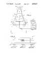
- FIG. 1depicts a cardiac activity probe and an associated computer in accordance with a preferred embodiment of of the invention.
- FIG. 2is an end view of the cardiac activity probe of FIG. 1 taken along line II--II thereof.
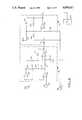
- FIG. 3is a schematic circuit diagram of electronic components of the probe of the preceding figures.
- FIG. 4is a detailed circuit diagram of the differential amplifier and band pass filter amplifier components of the probe which are shown in block form in FIG. 3.
- FIG. 5is a detailed circuit diagram of the optical isolator and interface driver circuits shown in block form in FIG. 3.
- FIGS. 6 through 11describes a detailed computer program for enabling computer graphic display of data produced by the probe of the preceding figures.
- FIG. 12describes another suitable computer program for displaying data transmitted to a computer by the probe.
- FIG. 13depicts a print out of an ECG from data produced by the probe.
- a cardiac probe unit 11in accordance with this particular embodiment of the invention has a housing member 12 which includes a triangular plate portion 13 and a thicker housing 14 at one surface of the plate.
- the housing 14contains electronic components which will hereinafter be described. Externally visible components of the housing 14 include a manually operable on-off switch 16, an openable battery compartment lid 17 and a signal output port 18.
- Plate portion 13defines an isosceles triangle with a base 19 that is shorter than the sides 21.
- First, second and third electrodes, 22, 23 and 24 respectively,are situated at the ends of conductive support posts, 26, 27, and 28 respectively, which extend outward from the surface 29 of plate 13 that is opposite from housing 14.
- First electrode 22is located at the apex of the triangular plate 13 at which sides 21 converge.
- Second electrode 23is at the right hand side of base 19 when the probe 11 is in the operating orientation shown in the drawings and third electrode 24 is at the left side of the base.
- the first, second and third electrodes 22, 23, 24may be hereinafter referred to respectively as the right arm electrode, the left leg electrode and the right leg electrode. This does not mean that the electrodes 22, 23, 24 contact those particular portions of the human body during use.
- the triangular plate 13is proportioned to fit over the frontal thoracial region of the human body with the right arm electrode 22 being over the sternum 30, left leg electrode 23 being over the lower ribs 31 at the left side of the body and right leg electrode being over the lower ribs at the right side of the body.
- Positioning of the electrodes 22, 23, 24 over bony regions of the bodyallows firmer pressure to be exerted and reduces artifact in the signals due to electrode movement. Such placement also reduces signal degradation from non-cardial muscle activity.
- the spacing of electrodes 22, 23, 24 from plate 13 by support posts 22, 23, 24enables firm contact of the electrodes with the skin by accomodating to the convexity of the human chest.
- the triangular configuration of the probe 11is particularly useful for women as it avoids the areas of the breasts.
- Each electrode 22, 23, 24preferably has a concave contact surface 32 and thus is essentially cup shaped. Pressure is then concentrated at a circle on the skin and this reduces electrical resistance and also reduces effects from body hair.
- electronic components of the probe 11include a first circuit stage 32 which is a low gain differential amplifier of the type having high common mode rejection.
- the first stage 32has inputs 33 and 34 connected to the right arm electrode 22 and left leg electrode 23 respectively.
- the right leg electrode 24in effect constitutes a chassis ground for the first stage 32 and certain other components of the probe 11 as will hereinafter be described in more detail.
- First stage 32produces a first analog signal indicative of voltage variations at right arm electrode 22 relative to the voltage at right leg electrode 24 and also produces a second analog signal indicative of voltage variations at left leg electrode 23 relative to the voltage at the right leg electrode and transmits a third analog signal indicative of the difference between the first and second analog signals to a second circuit stage 36.
- Sensing the voltage at electrodes 22 and 23 relative to the voltage at electrode 24rejects the effects of electrical artifacts, such as charges produced by nearby electrical equipment, which can appear on the body surface with a much larger amplitude than ECG signals.
- the second circuit stage 36is a band pass amplifier which eliminates direct current and low frequency components of the third analog signal to eliminate base line drift and which also eliminates high frequency components to further reduce electrical artifact such as residual power line signals and signals generated by surface muscle activity.
- Stage 36may typically be configured to transmit only frequencies in the range from about 0.5 Hz to about 25 Hz.
- the band pass amplifer 36also shifts the signal amplitude from +/- one volt to 2.5 volts +/- one volt to accomodate to the input signal acceptance range of this particular third circuit stage 37.
- the third circuit stage 37is an analog to digital signal convertor which may be of known construction and recieves the third analog signal from circuit stage 36.
- the clock circuit 38 of this particular analog to digital convertor 37causes sampling of the third analog signal at a frequency of 250 Hz and transmits an eight bit digital output signal in parallel form at each such sampling.
- the fourth circuit stage 39is a parallel to serial digital signal convertor which may also be of known construction. Convertor 39 converts the parallel eight bit signals received simultaneously on eight input lines 41 into sequential bit signals which can be transmitted on a single output line 42.
- the output signalling rate in this particular embodimentis 9,600 bits per second.
- the serial form signals from circuit stage 39are transmitted to the input circuit 43 of an optical isolator or coupler 44 which may also be of known internal construction.
- the input circuit 43converts the serial signal bits from electrical to optical form and the output circuit 46 of the isolator reconverts the optical signals back to electrical signal bits. This electrically isolates the electrodes 22, 23, and 24 from the computer 47 to which the probe 11 is coupled thereby eliminating any risk of electrical shock as there is no electrically conductive path between such components.
- Digitizing and serializing of the signals within the probe 11 prior to transmission of the signals through optical isolator 44contributes substantially to the objective of providing an inexpensive monitoring device.
- Digital optical isolators 44 and particularly single channel isolatorsare less costly than analog isolators which must sensitively respond to slight differences in signal voltage rather than to two distinctly different voltage levels as in the case of digital isolators.
- the sequence of serial signals from optical isolator 44is transmitted to the output port 18 of probe unit 11 through a computer interface driver circuit 48 within the the probe 11.
- Circuit 48operates as an amplifier and level shifter which converts the signal voltages into the standardized range required for the serial input ports 49 of personal computers 47.
- a four conductor cable 51provides for coupling of the probe 11 output port 18 with the serial port 49 which is present on personal computers 47 for the purpose of receiving digital signals in serial form from an external source.
- Cable 51has a connector 52 at one end compatible with the serial port 49 of the particular brand of computer 49 and has a connector 53 at the other end that is engagable with probe port 18 and which connect each of the standard four pins (not shown) of the computer serial port 49 with a separate one of four contacts 54, 56, 57 and 58 of probe port 18.
- the probe port 18, mating connector 53 and cable 51may, if desired, be of the low cost type used for telephone receiver installations as four conductors are used in each case.
- Cable 51connects contacts 56 and 57 with the "receive data” and “signal ground” pins, respectively of the computer serial port 49 and connects contacts 54 and 58 with the "terminal ready” and “transmit data” pins, respectively, of the computer port.
- Output signals from the interface driver 48are transmitted to the computer 47 through contact 56 with contact 57 being the signal ground conductor.
- the input circuit 43 of optical isolator 44 and circuit stages 36, 37, 38, and 39are provided with an independent D.C. power source 59.
- the probe 11includes a battery 61 connected to a voltage regulator 62 in series with the probe on-off switch 16.
- Regulator 62has positive and negative outputs B+ and B- which apply operating power, at constant voltages relative to the chassis ground defined by right leg electrode 24, to circuit stages 32 and 36. Only positive voltage from terminal B+ is is applied to stages 37 and 39 and isolator input circuit 43 which do not require bipolar power in this embodiment.
- FIG. 4depicts suitable circuit detail for the first and second circuit stages 32 and 36.
- right leg electrode 22 and left leg electrode 23are connected to the non-inverting inputs of a first pair of amplifiers 63 and 64 respectively which amplify the minute voltages that are sensed by the electrodes.
- the output of amplifier 63is connected to the output of amplifier 64 through three series connected resistors 66, 67 and 68.
- the circuit junction 69 between resistors 66 and 67is connected to the inverting input of amplifier 63 and the circuit junction 71 between resistors 67 and 68 connects to the inverting input of amplifier 64.
- the amplified voltage signals from amplifiers 63 and 64are respectively applied to the inverting and non-inverting inputs of a differential amplifier 73 through input resistors 74 and 76 respectively.
- a feedback resistance 77is connected across the inverting input and output of amplifier 73 and an adjustable resistance 78 is connected between the non-inverting input and ground. Resistance 78 may be adjusted to compensate for offset amplifier 73 and to null any common mode output.
- the first and second analog signal voltages produced by amplifiers 63 and 64are proportional to the voltages sensed by electrodes 22 and 23 respectively at any given time.
- Differential amplifier 73produces a third analog signal voltage which varies in accordance with variations of the difference between the first and second analog signals.
- the second circuit stage 36 or band pass filter amplifiermay include another amplifier 79 having a non-inverting input coupled to the output of the differential amplifier 73 through a capacitor 81 and which is also connected ground through a resistor 82.
- Capacitor 81 and resistor 82form a high pass filter which blocks direct current and supresses low frequency signal variations.
- resistor 83 and capacitor 84are connected in parallel across the inverting input and output of amplifier 79 and function as a high pass filter which eliminates high frequency artifact from the signal.
- An additional resistor 86 connected between the inverting input and groundoperates in conjunction with resistor 83 to establish the gain of the amplifier 79 to provide a signal voltage range compatible with the particular analog to digital convertor 37 to which the amplifier is coupled.
- Resistor 85 which connects in the inverting input to B-provides offset.
- the input circuit 43 of optical isolator 44has a light emitting diode 87 connected between the power source terminal B+ and ground in series with a resistor 88 and receives the serial form digital signals from parallel to serial signal convertor 39 at the circuit junction between the diode and resistor.
- the output circuit 46 of isolator 44includes a photosensitive transistor 89 of the type which exhibits a variable gain in response to changes in the light output of diode 87 produced by the incoming signals.
- the interface driver 48may have still another amplifier 91 which has an output connected to the receive data contact 56 of the probe output port 18.
- the positive and negative power inputs of amplifier 91are respectively connected to the transmit data contact 58 and terminal ready contact 54 of the output port 18 to supply operating voltage derived from the computer.
- a capacitor 92is connected across contacts 57 and 58 and another capacitor 93 is connected across contacts 54 and 57 to provide energy storage for the relatively high impedance power supply formed by transmit data and data terminal ready pins of the computer port.
- the photosensitive transistor 89 of optical isolator 44is connected across contacts 57 and 58 in series with a fixed resistor 94.
- the non-inverting input of amplifier 91connects to the circuit junction 96 between resistor 94 and photosensitive transistor 89 and also connects to ground contact 57 through a pair of series resistors 97 and 98.
- the inverting input of the amplifier 91connects to the circuit junction 99 between resistors 97 and 98.
- Amplifier 91 in conjunction with resistors 97 and 98acts as a comparator which converts the voltage variations across photosensitive transistor 89 to a voltage range that is compatible with the computer, for example to +/-5 volts for the EIA RS-232 format.
- the signals transmitted to computer 47may variously be utilized to provide a graphical display 100 of successive voltage fluctuations indicative of heart activity and/or to provide a print out of an ECG at a printer 101 coupled to the computer or for other purposes.
- the datamay, if desired, be stored on a disc by the computer 47.
- FIGS. 6 through 11describe a suitable detailed program for enabling computer graphic display of data produced by the probe.
- FIG. 12describes an alternate program which may also be used for the purpose.
- the inventionhas been herein described with respect to the monitoring of heart activity but can also be used for monitoring voltage variations between spaced areas on a surface in other contexts.
Landscapes
- Health & Medical Sciences (AREA)
- Life Sciences & Earth Sciences (AREA)
- Engineering & Computer Science (AREA)
- Heart & Thoracic Surgery (AREA)
- Molecular Biology (AREA)
- Biophysics (AREA)
- Pathology (AREA)
- Biomedical Technology (AREA)
- Veterinary Medicine (AREA)
- Medical Informatics (AREA)
- Physics & Mathematics (AREA)
- Surgery (AREA)
- Animal Behavior & Ethology (AREA)
- General Health & Medical Sciences (AREA)
- Public Health (AREA)
- Cardiology (AREA)
- Power Engineering (AREA)
- Measurement And Recording Of Electrical Phenomena And Electrical Characteristics Of The Living Body (AREA)
Abstract
Description
Claims (8)
Priority Applications (4)
| Application Number | Priority Date | Filing Date | Title |
|---|---|---|---|
| US07/095,314US4858617A (en) | 1987-09-10 | 1987-09-10 | Cardiac probe enabling use of personal computer for monitoring heart activity or the like |
| AU25302/88AAU2530288A (en) | 1987-09-10 | 1988-09-08 | Cardiac probe enabling use of a personal computer |
| PCT/US1988/003086WO1989002247A1 (en) | 1987-09-10 | 1988-09-08 | Cardiac probe enabling use of a personal computer |
| CA000576941ACA1326884C (en) | 1987-09-10 | 1988-09-09 | Cardiac probe enabling use of personal computer for monitoring heart activity or the like |
Applications Claiming Priority (1)
| Application Number | Priority Date | Filing Date | Title |
|---|---|---|---|
| US07/095,314US4858617A (en) | 1987-09-10 | 1987-09-10 | Cardiac probe enabling use of personal computer for monitoring heart activity or the like |
Publications (1)
| Publication Number | Publication Date |
|---|---|
| US4858617Atrue US4858617A (en) | 1989-08-22 |
Family
ID=22251334
Family Applications (1)
| Application Number | Title | Priority Date | Filing Date |
|---|---|---|---|
| US07/095,314Expired - LifetimeUS4858617A (en) | 1987-09-10 | 1987-09-10 | Cardiac probe enabling use of personal computer for monitoring heart activity or the like |
Country Status (4)
| Country | Link |
|---|---|
| US (1) | US4858617A (en) |
| AU (1) | AU2530288A (en) |
| CA (1) | CA1326884C (en) |
| WO (1) | WO1989002247A1 (en) |
Cited By (101)
| Publication number | Priority date | Publication date | Assignee | Title |
|---|---|---|---|---|
| US5027814A (en)* | 1989-05-19 | 1991-07-02 | Ventritex, Inc. | Implantable medical device employing an improved waveform digitization network |
| US5191891A (en)* | 1991-09-10 | 1993-03-09 | Ralin, Inc. | Portable ECG monitor/recorder |
| US5226425A (en)* | 1991-09-10 | 1993-07-13 | Ralin, Inc. | Portable ECG monitor/recorder |
| US5257631A (en)* | 1992-07-21 | 1993-11-02 | Wilk Peter J | Electrocardiographic method and device |
| US5307817A (en)* | 1989-01-27 | 1994-05-03 | Medese Ag | Biotelemetry method for the transmission of bioelectric potential defferences, and a device for the transmission of ECG signals |
| US5483967A (en)* | 1993-02-23 | 1996-01-16 | Ohtake; Tutomu | Bioelectric signal recording device |
| US5581369A (en)* | 1992-09-25 | 1996-12-03 | Ralin, Inc. | Apparatus and method for communicating electrocardiographic data to a facsimile machine |
| US5666958A (en)* | 1995-04-06 | 1997-09-16 | Rothenberg; Peter M. | Interface module for electrically connecting medical equipment |
| US5782238A (en)* | 1995-11-27 | 1998-07-21 | Beitler; Martin M. | Multiple electrode EKG device |
| US5782241A (en)* | 1993-04-22 | 1998-07-21 | O.D.A.M. Office De Distribution D'appareils Medicaux (Sa) | Sensor device for electrocardiogram |
| US5842978A (en)* | 1996-11-18 | 1998-12-01 | Levy; Itchak | Supplemental audio visual emergency reviewing apparatus and method |
| US6089235A (en)* | 1992-11-25 | 2000-07-18 | Scimed Life Systems, Inc. | Method of using an in vivo mechanical energy source |
| WO2000042904A1 (en)* | 1999-01-22 | 2000-07-27 | Del Mar Avionics | Long term, ambulatory physiological recorder |
| US20010047252A1 (en)* | 1997-01-10 | 2001-11-29 | Brown Stephen J. | Disease simulation system and method |
| US20030069753A1 (en)* | 1992-11-17 | 2003-04-10 | Brown Stephen J. | Multi-user remote health monitoring system with biometrics support |
| US6580948B2 (en)* | 2000-04-25 | 2003-06-17 | Medtronic, Inc. | Interface devices for instruments in communication with implantable medical devices |
| US20030120163A1 (en)* | 1997-07-31 | 2003-06-26 | Yoram Rudy | System and methods for noninvasive electrocardiographic imaging (ECGI) using generalized minimum residual (GMRes) |
| US20030176183A1 (en)* | 2001-04-02 | 2003-09-18 | Therasense, Inc. | Blood glucose tracking apparatus and methods |
| EP1364614A1 (en)* | 2002-05-20 | 2003-11-26 | NTT DoCoMo, Inc. | Voltage measuring device comprising fixing member, electrode and transmitter |
| US6772004B2 (en) | 1997-07-31 | 2004-08-03 | Case Western Reserve University | System and method for non-invasive electrocardiographic imaging |
| US20040193377A1 (en)* | 1999-03-22 | 2004-09-30 | Brown Stephen J. | Research data collection and analysis |
| US20040225233A1 (en)* | 2003-05-09 | 2004-11-11 | Frankowski Brian J. | Magnetic guidewires |
| US20040249999A1 (en)* | 2003-04-04 | 2004-12-09 | Connolly Brian Edmond | Method and system for transferring analyte test data |
| US20040267144A1 (en)* | 2003-06-25 | 2004-12-30 | Kuo Terry B. J. | Electrocardiogram signal converter and analog-to-digital conversion device thereof |
| US20050197587A1 (en)* | 1997-07-31 | 2005-09-08 | Case Western Reserve University | Determining a surface geometry of an object |
| US6968375B1 (en) | 1997-03-28 | 2005-11-22 | Health Hero Network, Inc. | Networked system for interactive communication and remote monitoring of individuals |
| US20060063996A1 (en)* | 2004-09-23 | 2006-03-23 | Lesourd Bonnie B | Disposable biomedical electrode having multiple connection sites |
| US20060235316A1 (en)* | 2002-10-18 | 2006-10-19 | Ungless Gary S | Cardiac monitoring apparatus and method |
| US20070093719A1 (en)* | 2005-10-20 | 2007-04-26 | Nichols Allen B Jr | Personal heart rhythm recording device |
| US20070118403A1 (en)* | 1992-11-17 | 2007-05-24 | Brown Stephen J | Method and apparatus for remote health monitoring and providing health related information |
| US7223236B2 (en) | 1992-11-17 | 2007-05-29 | Health Hero Network, Inc. | System and method for monitoring user-related data from a person |
| US20070156457A1 (en)* | 1994-05-23 | 2007-07-05 | Brown Stephen J | Method and apparatus for interactively monitoring a physiological condition and for interactively providing health-related information |
| US7260480B1 (en) | 2003-04-07 | 2007-08-21 | Health Hero Network, Inc. | Method and system for integrating feedback loops in medical knowledge development and healthcare management |
| US7297109B2 (en) | 1992-11-17 | 2007-11-20 | Health Hero Network, Inc. | Method and system for improving adherence with a diet program or other medical regimen |
| US7305348B1 (en) | 1996-02-20 | 2007-12-04 | Health Hero Network, Inc. | Aggregating and pooling health related information in a communication system with feedback |
| US20080059227A1 (en)* | 2006-08-31 | 2008-03-06 | Geoffrey Clapp | Health related location awareness |
| US7399276B1 (en) | 2003-05-08 | 2008-07-15 | Health Hero Network, Inc. | Remote health monitoring system |
| WO2008015667A3 (en)* | 2006-07-29 | 2009-04-16 | Cardicell Ltd | Device for mobile electrocardiogram recording |
| US7555436B2 (en) | 1997-01-16 | 2009-06-30 | Health Hero Network, Inc. | Personalized display of health information |
| WO2009087350A1 (en) | 2008-01-04 | 2009-07-16 | Central Manchester University Hospitals Nhs Foundation Trust | Electrocardiographic device and method |
| US7584108B2 (en) | 1996-12-23 | 2009-09-01 | Health Hero Network, Inc. | Network media access control system for encouraging patient compliance with a treatment plan |
| US7613590B2 (en) | 1992-11-17 | 2009-11-03 | Health Hero Network, Inc. | Modular microprocessor-based power tool system |
| US7620438B2 (en) | 2006-03-31 | 2009-11-17 | Abbott Diabetes Care Inc. | Method and system for powering an electronic device |
| US7624028B1 (en) | 1992-11-17 | 2009-11-24 | Health Hero Network, Inc. | Remote health monitoring and maintenance system |
| US20100042008A1 (en)* | 2008-08-14 | 2010-02-18 | David Amitai | ECG Data Acquisition Device |
| US7765112B2 (en) | 1996-10-16 | 2010-07-27 | Health Hero Network, Inc. | Multiple patient monitoring system for proactive health management |
| US7766829B2 (en) | 2005-11-04 | 2010-08-03 | Abbott Diabetes Care Inc. | Method and system for providing basal profile modification in analyte monitoring and management systems |
| US7811231B2 (en) | 2002-12-31 | 2010-10-12 | Abbott Diabetes Care Inc. | Continuous glucose monitoring system and methods of use |
| US7814143B2 (en) | 1997-03-10 | 2010-10-12 | Health Hero Network, Inc. | System and method for modifying documents sent over a communications network |
| US7860544B2 (en) | 1998-04-30 | 2010-12-28 | Abbott Diabetes Care Inc. | Analyte monitoring device and methods of use |
| US7920907B2 (en) | 2006-06-07 | 2011-04-05 | Abbott Diabetes Care Inc. | Analyte monitoring system and method |
| US7928850B2 (en) | 2007-05-08 | 2011-04-19 | Abbott Diabetes Care Inc. | Analyte monitoring system and methods |
| US8005690B2 (en) | 1998-09-25 | 2011-08-23 | Health Hero Network, Inc. | Dynamic modeling and scoring risk assessment |
| US8015033B2 (en) | 1994-04-26 | 2011-09-06 | Health Hero Network, Inc. | Treatment regimen compliance and efficacy with feedback |
| US8027809B2 (en) | 1992-11-17 | 2011-09-27 | Health Hero Network, Inc. | Home power management system |
| US8066639B2 (en) | 2003-06-10 | 2011-11-29 | Abbott Diabetes Care Inc. | Glucose measuring device for use in personal area network |
| US8078431B2 (en) | 1992-11-17 | 2011-12-13 | Health Hero Network, Inc. | Home power management system |
| US8078407B1 (en) | 1997-03-28 | 2011-12-13 | Health Hero Network, Inc. | System and method for identifying disease-influencing genes |
| US8095340B2 (en) | 1992-11-17 | 2012-01-10 | Health Hero Network, Inc. | Home power management system |
| US8103456B2 (en) | 2009-01-29 | 2012-01-24 | Abbott Diabetes Care Inc. | Method and device for early signal attenuation detection using blood glucose measurements |
| US20120022387A1 (en)* | 2010-05-21 | 2012-01-26 | Medicomp, Inc. | Retractable multi-use cardiac monitor |
| US8112240B2 (en) | 2005-04-29 | 2012-02-07 | Abbott Diabetes Care Inc. | Method and apparatus for providing leak detection in data monitoring and management systems |
| US8123686B2 (en) | 2007-03-01 | 2012-02-28 | Abbott Diabetes Care Inc. | Method and apparatus for providing rolling data in communication systems |
| US8149117B2 (en) | 2007-05-08 | 2012-04-03 | Abbott Diabetes Care Inc. | Analyte monitoring system and methods |
| US8226891B2 (en) | 2006-03-31 | 2012-07-24 | Abbott Diabetes Care Inc. | Analyte monitoring devices and methods therefor |
| US8287454B2 (en) | 1998-04-30 | 2012-10-16 | Abbott Diabetes Care Inc. | Analyte monitoring device and methods of use |
| US8346337B2 (en) | 1998-04-30 | 2013-01-01 | Abbott Diabetes Care Inc. | Analyte monitoring device and methods of use |
| EP2129282A4 (en)* | 2007-02-16 | 2013-01-23 | Radi Medical Systems | Measurement system to measure a physiological condition in a body |
| US8407063B2 (en) | 1992-11-17 | 2013-03-26 | Robert Bosch Healthcare Systems, Inc. | Multi-user remote health monitoring system with biometrics support |
| US8456301B2 (en) | 2007-05-08 | 2013-06-04 | Abbott Diabetes Care Inc. | Analyte monitoring system and methods |
| US8465425B2 (en) | 1998-04-30 | 2013-06-18 | Abbott Diabetes Care Inc. | Analyte monitoring device and methods of use |
| US8612159B2 (en) | 1998-04-30 | 2013-12-17 | Abbott Diabetes Care Inc. | Analyte monitoring device and methods of use |
| US8626521B2 (en) | 1997-11-21 | 2014-01-07 | Robert Bosch Healthcare Systems, Inc. | Public health surveillance system |
| US8652043B2 (en) | 2001-01-02 | 2014-02-18 | Abbott Diabetes Care Inc. | Analyte monitoring device and methods of use |
| US8665091B2 (en) | 2007-05-08 | 2014-03-04 | Abbott Diabetes Care Inc. | Method and device for determining elapsed sensor life |
| US8688188B2 (en) | 1998-04-30 | 2014-04-01 | Abbott Diabetes Care Inc. | Analyte monitoring device and methods of use |
| US8732188B2 (en) | 2007-02-18 | 2014-05-20 | Abbott Diabetes Care Inc. | Method and system for providing contextual based medication dosage determination |
| US8771183B2 (en) | 2004-02-17 | 2014-07-08 | Abbott Diabetes Care Inc. | Method and system for providing data communication in continuous glucose monitoring and management system |
| US20140206976A1 (en)* | 2011-03-11 | 2014-07-24 | Proteus Digital Health, Inc. | Wearable Personal Body Associated Device with Various Physical Configurations |
| US8930203B2 (en) | 2007-02-18 | 2015-01-06 | Abbott Diabetes Care Inc. | Multi-function analyte test device and methods therefor |
| US8974386B2 (en) | 1998-04-30 | 2015-03-10 | Abbott Diabetes Care Inc. | Analyte monitoring device and methods of use |
| US8993331B2 (en) | 2009-08-31 | 2015-03-31 | Abbott Diabetes Care Inc. | Analyte monitoring system and methods for managing power and noise |
| US9014779B2 (en) | 2010-02-01 | 2015-04-21 | Proteus Digital Health, Inc. | Data gathering system |
| US9066695B2 (en) | 1998-04-30 | 2015-06-30 | Abbott Diabetes Care Inc. | Analyte monitoring device and methods of use |
| US9226701B2 (en) | 2009-04-28 | 2016-01-05 | Abbott Diabetes Care Inc. | Error detection in critical repeating data in a wireless sensor system |
| US9270503B2 (en) | 2013-09-20 | 2016-02-23 | Proteus Digital Health, Inc. | Methods, devices and systems for receiving and decoding a signal in the presence of noise using slices and warping |
| US9314195B2 (en) | 2009-08-31 | 2016-04-19 | Abbott Diabetes Care Inc. | Analyte signal processing device and methods |
| US9320461B2 (en) | 2009-09-29 | 2016-04-26 | Abbott Diabetes Care Inc. | Method and apparatus for providing notification function in analyte monitoring systems |
| US9439566B2 (en) | 2008-12-15 | 2016-09-13 | Proteus Digital Health, Inc. | Re-wearable wireless device |
| US9577864B2 (en) | 2013-09-24 | 2017-02-21 | Proteus Digital Health, Inc. | Method and apparatus for use with received electromagnetic signal at a frequency not known exactly in advance |
| US9585584B2 (en) | 2010-05-21 | 2017-03-07 | Medicomp, Inc. | Physiological signal monitor with retractable wires |
| US9597010B2 (en) | 2005-04-28 | 2017-03-21 | Proteus Digital Health, Inc. | Communication system using an implantable device |
| US9659423B2 (en) | 2008-12-15 | 2017-05-23 | Proteus Digital Health, Inc. | Personal authentication apparatus system and method |
| US9756874B2 (en) | 2011-07-11 | 2017-09-12 | Proteus Digital Health, Inc. | Masticable ingestible product and communication system therefor |
| US9968306B2 (en) | 2012-09-17 | 2018-05-15 | Abbott Diabetes Care Inc. | Methods and apparatuses for providing adverse condition notification with enhanced wireless communication range in analyte monitoring systems |
| US9980669B2 (en) | 2011-11-07 | 2018-05-29 | Abbott Diabetes Care Inc. | Analyte monitoring device and methods |
| US10084880B2 (en) | 2013-11-04 | 2018-09-25 | Proteus Digital Health, Inc. | Social media networking based on physiologic information |
| US10398161B2 (en) | 2014-01-21 | 2019-09-03 | Proteus Digital Heal Th, Inc. | Masticable ingestible product and communication system therefor |
| US11158149B2 (en) | 2013-03-15 | 2021-10-26 | Otsuka Pharmaceutical Co., Ltd. | Personal authentication apparatus system and method |
| US11375938B2 (en) | 2008-08-14 | 2022-07-05 | Ticker Medical Ltd | Miniature ECG data acquisition device |
| US11793936B2 (en) | 2009-05-29 | 2023-10-24 | Abbott Diabetes Care Inc. | Medical device antenna systems having external antenna configurations |
Families Citing this family (6)
| Publication number | Priority date | Publication date | Assignee | Title |
|---|---|---|---|---|
| GB9117015D0 (en) | 1991-08-07 | 1991-09-18 | Software Solutions Ltd | Operation of computer systems |
| AUPO455297A0 (en)* | 1997-01-10 | 1997-01-30 | Micromedical Industries Limited | Universal ecg interface cable |
| AU749181B2 (en)* | 1997-01-10 | 2002-06-20 | Ventracor Limited | Universal ECG interface cable |
| FI104696B (en)* | 1998-05-04 | 2000-03-31 | Medikro Oy | skin potential measuring sensor |
| CA2373123A1 (en)* | 1999-05-06 | 2000-11-16 | Vladimir Jankov | Physiological signal acquisition cable |
| US7881778B2 (en) | 2006-09-28 | 2011-02-01 | The General Electric Company | Floating physiological data acquisition system with expandable ECG and EEG |
Citations (13)
| Publication number | Priority date | Publication date | Assignee | Title |
|---|---|---|---|---|
| US3222755A (en)* | 1961-08-02 | 1965-12-14 | Albert M Grass | Method of assembling an electrode |
| DE1907378A1 (en)* | 1968-02-26 | 1969-09-11 | Ceskoslovenska Akademie Ved | Electrode for determining a bioelectrical potential and method for its manufacture |
| US3650264A (en)* | 1968-12-04 | 1972-03-21 | Philips Corp | Apparatus for electro-medical investigation |
| US3830228A (en)* | 1972-06-12 | 1974-08-20 | M Foner | Biophysiological information processing device |
| US3830227A (en)* | 1966-05-17 | 1974-08-20 | H Green | Hand-held cardiac sound tone diagnostic device and method |
| US4013068A (en)* | 1974-10-15 | 1977-03-22 | Settle Wayne L | Electroencephalographic activated control system |
| US4109648A (en)* | 1975-12-18 | 1978-08-29 | National Research Development Corporation | Electrode assemblies |
| US4364397A (en)* | 1980-01-23 | 1982-12-21 | Medtronic, Inc. | Apparatus for monitoring the rhythm of a patient's heartbeat |
| US4417590A (en)* | 1978-06-09 | 1983-11-29 | Beckman Instruments, Inc. | Electroencephalograph |
| US4519398A (en)* | 1979-07-09 | 1985-05-28 | Del Mar Avionics | Method and apparatus for long-term monitoring of physiological activity to provide a compact portable record |
| US4583549A (en)* | 1984-05-30 | 1986-04-22 | Samir Manoli | ECG electrode pad |
| US4606352A (en)* | 1984-07-13 | 1986-08-19 | Purdue Research Foundation | Personal electrocardiogram monitor |
| US4624263A (en)* | 1983-08-25 | 1986-11-25 | Advanced Medical Electronics Developments Limited Partnership | Portable electrocardiograph with digitally-printing waveform display |
- 1987
- 1987-09-10USUS07/095,314patent/US4858617A/ennot_activeExpired - Lifetime
- 1988
- 1988-09-08WOPCT/US1988/003086patent/WO1989002247A1/enunknown
- 1988-09-08AUAU25302/88Apatent/AU2530288A/ennot_activeAbandoned
- 1988-09-09CACA000576941Apatent/CA1326884C/ennot_activeExpired - Fee Related
Patent Citations (13)
| Publication number | Priority date | Publication date | Assignee | Title |
|---|---|---|---|---|
| US3222755A (en)* | 1961-08-02 | 1965-12-14 | Albert M Grass | Method of assembling an electrode |
| US3830227A (en)* | 1966-05-17 | 1974-08-20 | H Green | Hand-held cardiac sound tone diagnostic device and method |
| DE1907378A1 (en)* | 1968-02-26 | 1969-09-11 | Ceskoslovenska Akademie Ved | Electrode for determining a bioelectrical potential and method for its manufacture |
| US3650264A (en)* | 1968-12-04 | 1972-03-21 | Philips Corp | Apparatus for electro-medical investigation |
| US3830228A (en)* | 1972-06-12 | 1974-08-20 | M Foner | Biophysiological information processing device |
| US4013068A (en)* | 1974-10-15 | 1977-03-22 | Settle Wayne L | Electroencephalographic activated control system |
| US4109648A (en)* | 1975-12-18 | 1978-08-29 | National Research Development Corporation | Electrode assemblies |
| US4417590A (en)* | 1978-06-09 | 1983-11-29 | Beckman Instruments, Inc. | Electroencephalograph |
| US4519398A (en)* | 1979-07-09 | 1985-05-28 | Del Mar Avionics | Method and apparatus for long-term monitoring of physiological activity to provide a compact portable record |
| US4364397A (en)* | 1980-01-23 | 1982-12-21 | Medtronic, Inc. | Apparatus for monitoring the rhythm of a patient's heartbeat |
| US4624263A (en)* | 1983-08-25 | 1986-11-25 | Advanced Medical Electronics Developments Limited Partnership | Portable electrocardiograph with digitally-printing waveform display |
| US4583549A (en)* | 1984-05-30 | 1986-04-22 | Samir Manoli | ECG electrode pad |
| US4606352A (en)* | 1984-07-13 | 1986-08-19 | Purdue Research Foundation | Personal electrocardiogram monitor |
Non-Patent Citations (2)
| Title |
|---|
| Makoto Takagi, "The Electrodes-Triangle" (Date not known), Annotations, pp. 427-428. |
| Makoto Takagi, The Electrodes Triangle (Date not known), Annotations, pp. 427 428.* |
Cited By (339)
| Publication number | Priority date | Publication date | Assignee | Title |
|---|---|---|---|---|
| US5307817A (en)* | 1989-01-27 | 1994-05-03 | Medese Ag | Biotelemetry method for the transmission of bioelectric potential defferences, and a device for the transmission of ECG signals |
| US5027814A (en)* | 1989-05-19 | 1991-07-02 | Ventritex, Inc. | Implantable medical device employing an improved waveform digitization network |
| US5191891A (en)* | 1991-09-10 | 1993-03-09 | Ralin, Inc. | Portable ECG monitor/recorder |
| US5226425A (en)* | 1991-09-10 | 1993-07-13 | Ralin, Inc. | Portable ECG monitor/recorder |
| US5365935A (en)* | 1991-09-10 | 1994-11-22 | Ralin, Inc. | Portable, multi-channel ECG data monitor/recorder |
| US5257631A (en)* | 1992-07-21 | 1993-11-02 | Wilk Peter J | Electrocardiographic method and device |
| US5581369A (en)* | 1992-09-25 | 1996-12-03 | Ralin, Inc. | Apparatus and method for communicating electrocardiographic data to a facsimile machine |
| US7223235B2 (en) | 1992-11-17 | 2007-05-29 | Health Hero Network, Inc. | System and method for monitoring blood pressure from a person |
| US9477939B2 (en) | 1992-11-17 | 2016-10-25 | Robert Bosch Healthcare Systems, Inc. | Radio frequency based remote health monitoring |
| US8024201B2 (en) | 1992-11-17 | 2011-09-20 | Health Hero Network, Inc. | Method and apparatus for remote health monitoring and providing health related information |
| US7761312B2 (en) | 1992-11-17 | 2010-07-20 | Health Hero Network, Inc. | Remote health monitoring and maintenance system |
| US8019618B2 (en) | 1992-11-17 | 2011-09-13 | Health Hero Network, Inc. | Report generation in a networked health-monitoring system |
| US7827040B2 (en) | 1992-11-17 | 2010-11-02 | Health Hero Network, Inc. | Patient control of health-related data in a remote patient monitoring system |
| US7264591B2 (en) | 1992-11-17 | 2007-09-04 | Health Hero Netowrk, Inc. | System and method for monitoring air flow from a person |
| US9215979B2 (en) | 1992-11-17 | 2015-12-22 | Robert Bosch Healthcare Systems, Inc. | Multi-user remote health monitoring system |
| US7689440B2 (en) | 1992-11-17 | 2010-03-30 | Health Hero Network, Inc. | Method and apparatus for remote health monitoring and providing health related information |
| US20030069753A1 (en)* | 1992-11-17 | 2003-04-10 | Brown Stephen J. | Multi-user remote health monitoring system with biometrics support |
| US8027809B2 (en) | 1992-11-17 | 2011-09-27 | Health Hero Network, Inc. | Home power management system |
| US7624028B1 (en) | 1992-11-17 | 2009-11-24 | Health Hero Network, Inc. | Remote health monitoring and maintenance system |
| US7941327B2 (en) | 1992-11-17 | 2011-05-10 | Health Hero Network, Inc. | User monitoring |
| US7941323B2 (en) | 1992-11-17 | 2011-05-10 | Health Hero Network, Inc. | Remote health monitoring and maintenance system |
| US8078431B2 (en) | 1992-11-17 | 2011-12-13 | Health Hero Network, Inc. | Home power management system |
| US7613590B2 (en) | 1992-11-17 | 2009-11-03 | Health Hero Network, Inc. | Modular microprocessor-based power tool system |
| US8015025B2 (en) | 1992-11-17 | 2011-09-06 | Health Hero Network, Inc. | Method and apparatus for remote health monitoring and providing health related information |
| US8095340B2 (en) | 1992-11-17 | 2012-01-10 | Health Hero Network, Inc. | Home power management system |
| US7853455B2 (en) | 1992-11-17 | 2010-12-14 | Health Hero Network, Inc. | Remote health monitoring and maintenance system |
| US7979284B2 (en) | 1992-11-17 | 2011-07-12 | Health Hero Network, Inc. | Interactive video based remote health monitoring system |
| US8617065B2 (en) | 1992-11-17 | 2013-12-31 | Robert Bosch Healthcare Systems, Inc. | Networked system for interactive communication and remote monitoring of individuals |
| US8249894B2 (en) | 1992-11-17 | 2012-08-21 | Robert Bosch Healthcare, Inc. | Networked remote patient monitoring with handheld devices |
| US7970620B2 (en) | 1992-11-17 | 2011-06-28 | Health Hero Network, Inc. | Multi-user remote health monitoring system with biometrics support |
| US8015030B2 (en) | 1992-11-17 | 2011-09-06 | Health Hero Network, Inc. | User-based health monitoring |
| US8260630B2 (en) | 1992-11-17 | 2012-09-04 | Health Hero Network, Inc. | Modular microprocessor-based appliance system |
| US7297109B2 (en) | 1992-11-17 | 2007-11-20 | Health Hero Network, Inc. | Method and system for improving adherence with a diet program or other medical regimen |
| US20030229514A2 (en)* | 1992-11-17 | 2003-12-11 | Stephen Brown | Multi-user remote health monitoring system with biometrics support |
| US7877274B2 (en) | 1992-11-17 | 2011-01-25 | Health Hero Network, Inc. | Messaging to remote patients in a networked health-monitoring system |
| US8489428B2 (en) | 1992-11-17 | 2013-07-16 | Robert Bosch Healthcare Systems, Inc. | Remote health monitoring and maintenance system |
| US7877276B2 (en) | 1992-11-17 | 2011-01-25 | Health Hero Network, Inc. | Messaging to remote patients in a networked health-monitoring system |
| US8419636B2 (en) | 1992-11-17 | 2013-04-16 | Robert Bosch Healthcare Systems, Inc. | Method and system for improving adherence with a diet program or other medical regimen |
| US7223236B2 (en) | 1992-11-17 | 2007-05-29 | Health Hero Network, Inc. | System and method for monitoring user-related data from a person |
| US8407063B2 (en) | 1992-11-17 | 2013-03-26 | Robert Bosch Healthcare Systems, Inc. | Multi-user remote health monitoring system with biometrics support |
| US20070118403A1 (en)* | 1992-11-17 | 2007-05-24 | Brown Stephen J | Method and apparatus for remote health monitoring and providing health related information |
| US6089235A (en)* | 1992-11-25 | 2000-07-18 | Scimed Life Systems, Inc. | Method of using an in vivo mechanical energy source |
| US5483967A (en)* | 1993-02-23 | 1996-01-16 | Ohtake; Tutomu | Bioelectric signal recording device |
| US5782241A (en)* | 1993-04-22 | 1998-07-21 | O.D.A.M. Office De Distribution D'appareils Medicaux (Sa) | Sensor device for electrocardiogram |
| US8032399B2 (en) | 1994-04-26 | 2011-10-04 | Health Hero Network, Inc. | Treatment regimen compliance and efficacy with feedback |
| US7904310B2 (en) | 1994-04-26 | 2011-03-08 | Health Hero Network, Inc. | Blood glucose monitoring system |
| US9123083B2 (en) | 1994-04-26 | 2015-09-01 | Robert Bosch Healthcare Systems, Inc. | Blood glucose monitoring system |
| US7966230B2 (en) | 1994-04-26 | 2011-06-21 | Health Hero Network, Inc. | Method and apparatus for remote health monitoring and providing health related information |
| US7901625B2 (en) | 1994-04-26 | 2011-03-08 | Health Hero Network, Inc. | System for performing diabetes self-care |
| US8015033B2 (en) | 1994-04-26 | 2011-09-06 | Health Hero Network, Inc. | Treatment regimen compliance and efficacy with feedback |
| US7908152B2 (en) | 1994-04-26 | 2011-03-15 | Health Hero Network, Inc. | Blood glucose monitoring system |
| US7877271B2 (en) | 1994-04-26 | 2011-01-25 | Health Hero Network, Inc. | Blood glucose monitoring system |
| US8655259B2 (en) | 1994-05-23 | 2014-02-18 | Robert Bosch Healthcare Systems, Inc. | System and method for monitoring a physiological condition |
| US8620206B2 (en) | 1994-05-23 | 2013-12-31 | Robert Bosch Healthcare Systems, Inc. | System and method for remote education |
| US7869852B2 (en) | 1994-05-23 | 2011-01-11 | Health Hero Network, Inc. | Diabetes management system |
| US7871376B2 (en) | 1994-05-23 | 2011-01-18 | Health Hero Network, Inc. | System and method for monitoring a physiological condition |
| US7867165B2 (en) | 1994-05-23 | 2011-01-11 | Health Hero Network, Inc. | System and method for monitoring a physiological condition |
| US7862506B2 (en) | 1994-05-23 | 2011-01-04 | Health Hero Network, Inc. | Diabetes management system |
| US8616895B2 (en) | 1994-05-23 | 2013-12-31 | Robert Bosch Healthcare Systems, Inc. | System and method for monitoring a physiological condition |
| US7972267B2 (en) | 1994-05-23 | 2011-07-05 | Health Hero Network, Inc. | Diabetes management system |
| US8644754B2 (en) | 1994-05-23 | 2014-02-04 | Robert Bosch Healthcare Systems, Inc. | Method and apparatus for interactively monitoring a physiological condition and for interactively providing health-related information |
| US20070156457A1 (en)* | 1994-05-23 | 2007-07-05 | Brown Stephen J | Method and apparatus for interactively monitoring a physiological condition and for interactively providing health-related information |
| US20070259323A1 (en)* | 1994-05-23 | 2007-11-08 | Brown Stephen J | System and method for remote education using a memory card |
| US5666958A (en)* | 1995-04-06 | 1997-09-16 | Rothenberg; Peter M. | Interface module for electrically connecting medical equipment |
| US7684999B2 (en) | 1995-06-07 | 2010-03-23 | Health Hero Network, Inc. | User-based health monitoring |
| US7258666B2 (en) | 1995-06-07 | 2007-08-21 | Health Hero Network, Inc. | System and methods for monitoring a patient's heart condition |
| US5782238A (en)* | 1995-11-27 | 1998-07-21 | Beitler; Martin M. | Multiple electrode EKG device |
| US7305348B1 (en) | 1996-02-20 | 2007-12-04 | Health Hero Network, Inc. | Aggregating and pooling health related information in a communication system with feedback |
| US7778845B2 (en) | 1996-10-16 | 2010-08-17 | Health Hero Network, Inc. | Multiple patient monitoring system for proactive health management |
| US7765112B2 (en) | 1996-10-16 | 2010-07-27 | Health Hero Network, Inc. | Multiple patient monitoring system for proactive health management |
| US7840420B2 (en) | 1996-10-16 | 2010-11-23 | Health Hero Network, Inc. | Multiple patient monitoring system for proactive health management |
| US7769605B2 (en) | 1996-10-16 | 2010-08-03 | Health Hero Network, Inc. | Multiple patient monitoring system for proactive health management |
| US5842978A (en)* | 1996-11-18 | 1998-12-01 | Levy; Itchak | Supplemental audio visual emergency reviewing apparatus and method |
| US7590549B2 (en) | 1996-12-23 | 2009-09-15 | Health Hero Network, Inc. | Network media access control system for encouraging patient compliance with a treatment plan |
| US7636667B2 (en) | 1996-12-23 | 2009-12-22 | Health Hero Networks, Inc. | Network media access control system for encouraging patient compliance with a treatment plan |
| US7584108B2 (en) | 1996-12-23 | 2009-09-01 | Health Hero Network, Inc. | Network media access control system for encouraging patient compliance with a treatment plan |
| USRE43316E1 (en) | 1997-01-10 | 2012-04-17 | Health Hero Network, Inc. | Diabetes management system and method for controlling blood glucose |
| US20010047252A1 (en)* | 1997-01-10 | 2001-11-29 | Brown Stephen J. | Disease simulation system and method |
| US7643971B2 (en) | 1997-01-10 | 2010-01-05 | Health Hero Network, Inc. | Disease simulation system and method |
| US7167818B2 (en) | 1997-01-10 | 2007-01-23 | Health Hero Network, Inc. | Disease simulation system and method |
| US7392167B2 (en) | 1997-01-10 | 2008-06-24 | Health Hero Network, Inc. | Disease simulation system and method |
| US7613621B2 (en) | 1997-01-16 | 2009-11-03 | Health Hero Network, Inc. | Personalized body image |
| US7925522B2 (en) | 1997-01-16 | 2011-04-12 | Health Hero Network, Inc. | Personalized body image |
| US7555436B2 (en) | 1997-01-16 | 2009-06-30 | Health Hero Network, Inc. | Personalized display of health information |
| US7814143B2 (en) | 1997-03-10 | 2010-10-12 | Health Hero Network, Inc. | System and method for modifying documents sent over a communications network |
| US6968375B1 (en) | 1997-03-28 | 2005-11-22 | Health Hero Network, Inc. | Networked system for interactive communication and remote monitoring of individuals |
| US7252636B2 (en) | 1997-03-28 | 2007-08-07 | Health Hero Network, Inc. | Networked system for interactive communication and remote monitoring of individuals |
| US7730177B2 (en) | 1997-03-28 | 2010-06-01 | Health Hero Network, Inc. | Networked system for interactive communication and remote monitoring of individuals |
| US7822625B2 (en) | 1997-03-28 | 2010-10-26 | Health Hero Network, Inc. | Networked system for interactive communication and remote monitoring of individuals |
| US7707270B2 (en) | 1997-03-28 | 2010-04-27 | Health Hero Network, Inc. | Networked system for interactive communication and remote monitoring of individuals |
| US8078407B1 (en) | 1997-03-28 | 2011-12-13 | Health Hero Network, Inc. | System and method for identifying disease-influencing genes |
| US7587469B2 (en) | 1997-03-28 | 2009-09-08 | Health Hero Network, Inc. | Audio instructions for appliances |
| US8140663B2 (en) | 1997-03-28 | 2012-03-20 | Health Hero Network, Inc. | Networked system for interactive communication and remote monitoring of individuals |
| US7533171B2 (en) | 1997-03-28 | 2009-05-12 | Health Hero Network, Inc. | Networked system for interactive communication and remote monitoring of individuals |
| US7516192B2 (en) | 1997-03-28 | 2009-04-07 | Health Hero Network, Inc. | Networked system for interactive communication and remote monitoring of individuals |
| US8990336B2 (en) | 1997-03-28 | 2015-03-24 | Robert Bosch Healthcare Systems, Inc. | Networked system for interactive communication and remote monitoring of individuals |
| US8353827B2 (en) | 1997-03-28 | 2013-01-15 | Robert Bosch Healthcare Systems, Inc. | Networked system for interactive communication and remote monitoring of individuals |
| US7320030B2 (en) | 1997-03-28 | 2008-01-15 | Health Hero Network, Inc. | Remote health monitoring apparatus using scripted communications |
| US7870249B2 (en) | 1997-03-28 | 2011-01-11 | Health Hero Network, Inc. | Networked system for interactive communication and remote monitoring of individuals |
| US7310668B2 (en) | 1997-03-28 | 2007-12-18 | Health Hero Network, Inc. | Remotely monitoring an individual using scripted communications |
| US7734718B2 (en) | 1997-03-28 | 2010-06-08 | Health Hero Network, Inc. | Smart appliance functionality |
| US20060294233A1 (en)* | 1997-03-28 | 2006-12-28 | Health Hero Network, Inc. | Networked system for interactive communication and remote monitoring of individuals |
| US8608653B2 (en) | 1997-03-28 | 2013-12-17 | Robert Bosch Gmbh | Networked system for interactive communication and remote monitoring of individuals |
| US7987100B2 (en) | 1997-03-28 | 2011-07-26 | Health Hero Network, Inc. | Networked system for interactive communication and remote monitoring of individuals |
| US8959198B2 (en) | 1997-03-28 | 2015-02-17 | Robert Bosch Healthcare Systems, Inc. | Optimizing oxygen tank deliver or refills for COPD patients through measurement of blood oxygen levels |
| US8870762B2 (en) | 1997-03-28 | 2014-10-28 | Robert Bosch Gmbh | Electronic data capture in clinical and pharmaceutical trials |
| US7921186B2 (en) | 1997-03-28 | 2011-04-05 | Health Hero Network, Inc. | Networked system for interactive communication and remote monitoring of individuals |
| US20050197587A1 (en)* | 1997-07-31 | 2005-09-08 | Case Western Reserve University | Determining a surface geometry of an object |
| US6772004B2 (en) | 1997-07-31 | 2004-08-03 | Case Western Reserve University | System and method for non-invasive electrocardiographic imaging |
| US6975900B2 (en) | 1997-07-31 | 2005-12-13 | Case Western Reserve University | Systems and methods for determining a surface geometry |
| US7016719B2 (en) | 1997-07-31 | 2006-03-21 | Case Western Reserve University | System and methods for noninvasive electrocardiographic imaging (ECGI) using generalized minimum residual (GMRes) |
| US7471973B2 (en) | 1997-07-31 | 2008-12-30 | Case Western Reserve University | Determining a surface geometry of an object |
| US20030120163A1 (en)* | 1997-07-31 | 2003-06-26 | Yoram Rudy | System and methods for noninvasive electrocardiographic imaging (ECGI) using generalized minimum residual (GMRes) |
| US8626521B2 (en) | 1997-11-21 | 2014-01-07 | Robert Bosch Healthcare Systems, Inc. | Public health surveillance system |
| US8372005B2 (en) | 1998-04-30 | 2013-02-12 | Abbott Diabetes Care Inc. | Analyte monitoring device and methods of use |
| US8357091B2 (en) | 1998-04-30 | 2013-01-22 | Abbott Diabetes Care Inc. | Analyte monitoring device and methods of use |
| US8734346B2 (en) | 1998-04-30 | 2014-05-27 | Abbott Diabetes Care Inc. | Analyte monitoring device and methods of use |
| US8672844B2 (en) | 1998-04-30 | 2014-03-18 | Abbott Diabetes Care Inc. | Analyte monitoring device and methods of use |
| US7885699B2 (en) | 1998-04-30 | 2011-02-08 | Abbott Diabetes Care Inc. | Analyte monitoring device and methods of use |
| US8670815B2 (en) | 1998-04-30 | 2014-03-11 | Abbott Diabetes Care Inc. | Analyte monitoring device and methods of use |
| US7869853B1 (en) | 1998-04-30 | 2011-01-11 | Abbott Diabetes Care Inc. | Analyte monitoring device and methods of use |
| US7860544B2 (en) | 1998-04-30 | 2010-12-28 | Abbott Diabetes Care Inc. | Analyte monitoring device and methods of use |
| US10478108B2 (en) | 1998-04-30 | 2019-11-19 | Abbott Diabetes Care Inc. | Analyte monitoring device and methods of use |
| US8734348B2 (en) | 1998-04-30 | 2014-05-27 | Abbott Diabetes Care Inc. | Analyte monitoring device and methods of use |
| US8666469B2 (en) | 1998-04-30 | 2014-03-04 | Abbott Diabetes Care Inc. | Analyte monitoring device and methods of use |
| US8660627B2 (en) | 1998-04-30 | 2014-02-25 | Abbott Diabetes Care Inc. | Analyte monitoring device and methods of use |
| US8649841B2 (en) | 1998-04-30 | 2014-02-11 | Abbott Diabetes Care Inc. | Analyte monitoring device and methods of use |
| US8641619B2 (en) | 1998-04-30 | 2014-02-04 | Abbott Diabetes Care Inc. | Analyte monitoring device and methods of use |
| US8622906B2 (en) | 1998-04-30 | 2014-01-07 | Abbott Diabetes Care Inc. | Analyte monitoring device and methods of use |
| US8738109B2 (en) | 1998-04-30 | 2014-05-27 | Abbott Diabetes Care Inc. | Analyte monitoring device and methods of use |
| US8744545B2 (en) | 1998-04-30 | 2014-06-03 | Abbott Diabetes Care Inc. | Analyte monitoring device and methods of use |
| US8617071B2 (en) | 1998-04-30 | 2013-12-31 | Abbott Diabetes Care Inc. | Analyte monitoring device and methods of use |
| US8612159B2 (en) | 1998-04-30 | 2013-12-17 | Abbott Diabetes Care Inc. | Analyte monitoring device and methods of use |
| US9326714B2 (en) | 1998-04-30 | 2016-05-03 | Abbott Diabetes Care Inc. | Analyte monitoring device and methods of use |
| US8597189B2 (en) | 1998-04-30 | 2013-12-03 | Abbott Diabetes Care Inc. | Analyte monitoring device and methods of use |
| US8774887B2 (en) | 1998-04-30 | 2014-07-08 | Abbott Diabetes Care Inc. | Analyte monitoring device and methods of use |
| US9072477B2 (en) | 1998-04-30 | 2015-07-07 | Abbott Diabetes Care Inc. | Analyte monitoring device and methods of use |
| US9066694B2 (en) | 1998-04-30 | 2015-06-30 | Abbott Diabetes Care Inc. | Analyte monitoring device and methods of use |
| US8840553B2 (en) | 1998-04-30 | 2014-09-23 | Abbott Diabetes Care Inc. | Analyte monitoring device and methods of use |
| US8162829B2 (en) | 1998-04-30 | 2012-04-24 | Abbott Diabetes Care Inc. | Analyte monitoring device and methods of use |
| US8175673B2 (en) | 1998-04-30 | 2012-05-08 | Abbott Diabetes Care Inc. | Analyte monitoring device and methods of use |
| US8177716B2 (en) | 1998-04-30 | 2012-05-15 | Abbott Diabetes Care Inc. | Analyte monitoring device and methods of use |
| US8480580B2 (en) | 1998-04-30 | 2013-07-09 | Abbott Diabetes Care Inc. | Analyte monitoring device and methods of use |
| US8224413B2 (en) | 1998-04-30 | 2012-07-17 | Abbott Diabetes Care Inc. | Analyte monitoring device and methods of use |
| US9066697B2 (en) | 1998-04-30 | 2015-06-30 | Abbott Diabetes Care Inc. | Analyte monitoring device and methods of use |
| US8226557B2 (en) | 1998-04-30 | 2012-07-24 | Abbott Diabetes Care Inc. | Analyte monitoring device and methods of use |
| US8226555B2 (en) | 1998-04-30 | 2012-07-24 | Abbott Diabetes Care Inc. | Analyte monitoring device and methods of use |
| US8226558B2 (en) | 1998-04-30 | 2012-07-24 | Abbott Diabetes Care Inc. | Analyte monitoring device and methods of use |
| US8231532B2 (en) | 1998-04-30 | 2012-07-31 | Abbott Diabetes Care Inc. | Analyte monitoring device and methods of use |
| US8880137B2 (en) | 1998-04-30 | 2014-11-04 | Abbott Diabetes Care Inc. | Analyte monitoring device and methods of use |
| US8235896B2 (en) | 1998-04-30 | 2012-08-07 | Abbott Diabetes Care Inc. | Analyte monitoring device and methods of use |
| US9066695B2 (en) | 1998-04-30 | 2015-06-30 | Abbott Diabetes Care Inc. | Analyte monitoring device and methods of use |
| US8255031B2 (en) | 1998-04-30 | 2012-08-28 | Abbott Diabetes Care Inc. | Analyte monitoring device and methods of use |
| US8473021B2 (en) | 1998-04-30 | 2013-06-25 | Abbott Diabetes Care Inc. | Analyte monitoring device and methods of use |
| US8260392B2 (en) | 1998-04-30 | 2012-09-04 | Abbott Diabetes Care Inc. | Analyte monitoring device and methods of use |
| US8265726B2 (en) | 1998-04-30 | 2012-09-11 | Abbott Diabetes Care Inc. | Analyte monitoring device and methods of use |
| US8465425B2 (en) | 1998-04-30 | 2013-06-18 | Abbott Diabetes Care Inc. | Analyte monitoring device and methods of use |
| US8275439B2 (en) | 1998-04-30 | 2012-09-25 | Abbott Diabetes Care Inc. | Analyte monitoring device and methods of use |
| US8273022B2 (en) | 1998-04-30 | 2012-09-25 | Abbott Diabetes Care Inc. | Analyte monitoring device and methods of use |
| US8287454B2 (en) | 1998-04-30 | 2012-10-16 | Abbott Diabetes Care Inc. | Analyte monitoring device and methods of use |
| US8306598B2 (en) | 1998-04-30 | 2012-11-06 | Abbott Diabetes Care Inc. | Analyte monitoring device and methods of use |
| US8346336B2 (en) | 1998-04-30 | 2013-01-01 | Abbott Diabetes Care Inc. | Analyte monitoring device and methods of use |
| US8346337B2 (en) | 1998-04-30 | 2013-01-01 | Abbott Diabetes Care Inc. | Analyte monitoring device and methods of use |
| US9042953B2 (en) | 1998-04-30 | 2015-05-26 | Abbott Diabetes Care Inc. | Analyte monitoring device and methods of use |
| US8353829B2 (en) | 1998-04-30 | 2013-01-15 | Abbott Diabetes Care Inc. | Analyte monitoring device and methods of use |
| US8688188B2 (en) | 1998-04-30 | 2014-04-01 | Abbott Diabetes Care Inc. | Analyte monitoring device and methods of use |
| US8974386B2 (en) | 1998-04-30 | 2015-03-10 | Abbott Diabetes Care Inc. | Analyte monitoring device and methods of use |
| US9011331B2 (en) | 1998-04-30 | 2015-04-21 | Abbott Diabetes Care Inc. | Analyte monitoring device and methods of use |
| US8366614B2 (en) | 1998-04-30 | 2013-02-05 | Abbott Diabetes Care Inc. | Analyte monitoring device and methods of use |
| US8409131B2 (en) | 1998-04-30 | 2013-04-02 | Abbott Diabetes Care Inc. | Analyte monitoring device and methods of use |
| US8380273B2 (en) | 1998-04-30 | 2013-02-19 | Abbott Diabetes Care Inc. | Analyte monitoring device and methods of use |
| US8391945B2 (en) | 1998-04-30 | 2013-03-05 | Abbott Diabetes Care Inc. | Analyte monitoring device and methods of use |
| US9014773B2 (en) | 1998-04-30 | 2015-04-21 | Abbott Diabetes Care Inc. | Analyte monitoring device and methods of use |
| US8005690B2 (en) | 1998-09-25 | 2011-08-23 | Health Hero Network, Inc. | Dynamic modeling and scoring risk assessment |
| US8521546B2 (en) | 1998-09-25 | 2013-08-27 | Health Hero Network | Dynamic modeling and scoring risk assessment |
| US6117077A (en)* | 1999-01-22 | 2000-09-12 | Del Mar Medical Systems, Llc | Long-term, ambulatory physiological recorder |
| WO2000042904A1 (en)* | 1999-01-22 | 2000-07-27 | Del Mar Avionics | Long term, ambulatory physiological recorder |
| US20040193377A1 (en)* | 1999-03-22 | 2004-09-30 | Brown Stephen J. | Research data collection and analysis |
| US8527206B2 (en) | 1999-03-22 | 2013-09-03 | Robert Bosch Gmbh | Research data collection and analysis |
| US6580948B2 (en)* | 2000-04-25 | 2003-06-17 | Medtronic, Inc. | Interface devices for instruments in communication with implantable medical devices |
| US9011332B2 (en) | 2001-01-02 | 2015-04-21 | Abbott Diabetes Care Inc. | Analyte monitoring device and methods of use |
| US8668645B2 (en) | 2001-01-02 | 2014-03-11 | Abbott Diabetes Care Inc. | Analyte monitoring device and methods of use |
| US8652043B2 (en) | 2001-01-02 | 2014-02-18 | Abbott Diabetes Care Inc. | Analyte monitoring device and methods of use |
| US9498159B2 (en) | 2001-01-02 | 2016-11-22 | Abbott Diabetes Care Inc. | Analyte monitoring device and methods of use |
| US9610034B2 (en) | 2001-01-02 | 2017-04-04 | Abbott Diabetes Care Inc. | Analyte monitoring device and methods of use |
| US7041468B2 (en) | 2001-04-02 | 2006-05-09 | Therasense, Inc. | Blood glucose tracking apparatus and methods |
| US8268243B2 (en) | 2001-04-02 | 2012-09-18 | Abbott Diabetes Care Inc. | Blood glucose tracking apparatus and methods |
| US8236242B2 (en) | 2001-04-02 | 2012-08-07 | Abbott Diabetes Care Inc. | Blood glucose tracking apparatus and methods |
| US7976778B2 (en) | 2001-04-02 | 2011-07-12 | Abbott Diabetes Care Inc. | Blood glucose tracking apparatus |
| US20030176183A1 (en)* | 2001-04-02 | 2003-09-18 | Therasense, Inc. | Blood glucose tracking apparatus and methods |
| US8765059B2 (en) | 2001-04-02 | 2014-07-01 | Abbott Diabetes Care Inc. | Blood glucose tracking apparatus |
| US9477811B2 (en) | 2001-04-02 | 2016-10-25 | Abbott Diabetes Care Inc. | Blood glucose tracking apparatus and methods |
| US20040015094A1 (en)* | 2002-05-20 | 2004-01-22 | Ntt Docomo, Inc. | Measuring device |
| EP1364614B1 (en)* | 2002-05-20 | 2009-07-08 | NTT DoCoMo, Inc. | Voltage measuring device comprising fixing member, electrode and transmitter |
| EP1364614A1 (en)* | 2002-05-20 | 2003-11-26 | NTT DoCoMo, Inc. | Voltage measuring device comprising fixing member, electrode and transmitter |
| US20060235316A1 (en)* | 2002-10-18 | 2006-10-19 | Ungless Gary S | Cardiac monitoring apparatus and method |
| US7811231B2 (en) | 2002-12-31 | 2010-10-12 | Abbott Diabetes Care Inc. | Continuous glucose monitoring system and methods of use |
| US9962091B2 (en) | 2002-12-31 | 2018-05-08 | Abbott Diabetes Care Inc. | Continuous glucose monitoring system and methods of use |
| US8622903B2 (en) | 2002-12-31 | 2014-01-07 | Abbott Diabetes Care Inc. | Continuous glucose monitoring system and methods of use |
| US10750952B2 (en) | 2002-12-31 | 2020-08-25 | Abbott Diabetes Care Inc. | Continuous glucose monitoring system and methods of use |
| US10039881B2 (en) | 2002-12-31 | 2018-08-07 | Abbott Diabetes Care Inc. | Method and system for providing data communication in continuous glucose monitoring and management system |
| US8187183B2 (en) | 2002-12-31 | 2012-05-29 | Abbott Diabetes Care Inc. | Continuous glucose monitoring system and methods of use |
| US8682598B2 (en) | 2003-04-04 | 2014-03-25 | Abbott Laboratories | Method and system for transferring analyte test data |
| US8437966B2 (en) | 2003-04-04 | 2013-05-07 | Abbott Diabetes Care Inc. | Method and system for transferring analyte test data |
| US20040249999A1 (en)* | 2003-04-04 | 2004-12-09 | Connolly Brian Edmond | Method and system for transferring analyte test data |
| US8483974B2 (en) | 2003-04-04 | 2013-07-09 | Abbott Diabetes Care Inc. | Method and system for transferring analyte test data |
| US7587287B2 (en) | 2003-04-04 | 2009-09-08 | Abbott Diabetes Care Inc. | Method and system for transferring analyte test data |
| US8560250B2 (en) | 2003-04-04 | 2013-10-15 | Abbott Laboratories | Method and system for transferring analyte test data |
| US7260480B1 (en) | 2003-04-07 | 2007-08-21 | Health Hero Network, Inc. | Method and system for integrating feedback loops in medical knowledge development and healthcare management |
| US7399276B1 (en) | 2003-05-08 | 2008-07-15 | Health Hero Network, Inc. | Remote health monitoring system |
| US8945009B2 (en) | 2003-05-08 | 2015-02-03 | Robert Bosch Heathcare Systems, Inc. | Remote health monitoring system |
| US20040225233A1 (en)* | 2003-05-09 | 2004-11-11 | Frankowski Brian J. | Magnetic guidewires |
| US8647269B2 (en) | 2003-06-10 | 2014-02-11 | Abbott Diabetes Care Inc. | Glucose measuring device for use in personal area network |
| US9730584B2 (en) | 2003-06-10 | 2017-08-15 | Abbott Diabetes Care Inc. | Glucose measuring device for use in personal area network |
| US8066639B2 (en) | 2003-06-10 | 2011-11-29 | Abbott Diabetes Care Inc. | Glucose measuring device for use in personal area network |
| US8512239B2 (en) | 2003-06-10 | 2013-08-20 | Abbott Diabetes Care Inc. | Glucose measuring device for use in personal area network |
| US20040267144A1 (en)* | 2003-06-25 | 2004-12-30 | Kuo Terry B. J. | Electrocardiogram signal converter and analog-to-digital conversion device thereof |
| US8771183B2 (en) | 2004-02-17 | 2014-07-08 | Abbott Diabetes Care Inc. | Method and system for providing data communication in continuous glucose monitoring and management system |
| GB2418364B (en)* | 2004-09-23 | 2009-09-09 | Gen Electric | Disposable biomedical electrode having multiple connection sites |
| US20060063996A1 (en)* | 2004-09-23 | 2006-03-23 | Lesourd Bonnie B | Disposable biomedical electrode having multiple connection sites |
| GB2418364A (en)* | 2004-09-23 | 2006-03-29 | Gen Electric | Disposable medical skin electrode with multiple connection points |
| US7164939B2 (en) | 2004-09-23 | 2007-01-16 | The General Electric Company | Disposable biomedical electrode having multiple connection sites |
| US9597010B2 (en) | 2005-04-28 | 2017-03-21 | Proteus Digital Health, Inc. | Communication system using an implantable device |
| US8112240B2 (en) | 2005-04-29 | 2012-02-07 | Abbott Diabetes Care Inc. | Method and apparatus for providing leak detection in data monitoring and management systems |
| US20070093719A1 (en)* | 2005-10-20 | 2007-04-26 | Nichols Allen B Jr | Personal heart rhythm recording device |
| US11399748B2 (en) | 2005-11-01 | 2022-08-02 | Abbott Diabetes Care Inc. | Analyte monitoring device and methods of use |
| US10952652B2 (en) | 2005-11-01 | 2021-03-23 | Abbott Diabetes Care Inc. | Analyte monitoring device and methods of use |
| US11363975B2 (en) | 2005-11-01 | 2022-06-21 | Abbott Diabetes Care Inc. | Analyte monitoring device and methods of use |
| US9078607B2 (en) | 2005-11-01 | 2015-07-14 | Abbott Diabetes Care Inc. | Analyte monitoring device and methods of use |
| US9326716B2 (en) | 2005-11-01 | 2016-05-03 | Abbott Diabetes Care Inc. | Analyte monitoring device and methods of use |
| US11272867B2 (en) | 2005-11-01 | 2022-03-15 | Abbott Diabetes Care Inc. | Analyte monitoring device and methods of use |
| US10201301B2 (en) | 2005-11-01 | 2019-02-12 | Abbott Diabetes Care Inc. | Analyte monitoring device and methods of use |
| US8915850B2 (en) | 2005-11-01 | 2014-12-23 | Abbott Diabetes Care Inc. | Analyte monitoring device and methods of use |
| US8920319B2 (en) | 2005-11-01 | 2014-12-30 | Abbott Diabetes Care Inc. | Analyte monitoring device and methods of use |
| US10231654B2 (en) | 2005-11-01 | 2019-03-19 | Abbott Diabetes Care Inc. | Analyte monitoring device and methods of use |
| US11911151B1 (en) | 2005-11-01 | 2024-02-27 | Abbott Diabetes Care Inc. | Analyte monitoring device and methods of use |
| US11103165B2 (en) | 2005-11-01 | 2021-08-31 | Abbott Diabetes Care Inc. | Analyte monitoring device and methods of use |
| US7766829B2 (en) | 2005-11-04 | 2010-08-03 | Abbott Diabetes Care Inc. | Method and system for providing basal profile modification in analyte monitoring and management systems |
| US11538580B2 (en) | 2005-11-04 | 2022-12-27 | Abbott Diabetes Care Inc. | Method and system for providing basal profile modification in analyte monitoring and management systems |
| US9323898B2 (en) | 2005-11-04 | 2016-04-26 | Abbott Diabetes Care Inc. | Method and system for providing basal profile modification in analyte monitoring and management systems |
| US9669162B2 (en) | 2005-11-04 | 2017-06-06 | Abbott Diabetes Care Inc. | Method and system for providing basal profile modification in analyte monitoring and management systems |
| US8585591B2 (en) | 2005-11-04 | 2013-11-19 | Abbott Diabetes Care Inc. | Method and system for providing basal profile modification in analyte monitoring and management systems |
| US8226891B2 (en) | 2006-03-31 | 2012-07-24 | Abbott Diabetes Care Inc. | Analyte monitoring devices and methods therefor |
| US8597575B2 (en) | 2006-03-31 | 2013-12-03 | Abbott Diabetes Care Inc. | Analyte monitoring devices and methods therefor |
| US8593109B2 (en) | 2006-03-31 | 2013-11-26 | Abbott Diabetes Care Inc. | Method and system for powering an electronic device |
| US7620438B2 (en) | 2006-03-31 | 2009-11-17 | Abbott Diabetes Care Inc. | Method and system for powering an electronic device |
| US9625413B2 (en) | 2006-03-31 | 2017-04-18 | Abbott Diabetes Care Inc. | Analyte monitoring devices and methods therefor |
| US8933664B2 (en) | 2006-03-31 | 2015-01-13 | Abbott Diabetes Care Inc. | Method and system for powering an electronic device |
| US9039975B2 (en) | 2006-03-31 | 2015-05-26 | Abbott Diabetes Care Inc. | Analyte monitoring devices and methods therefor |
| US9743863B2 (en) | 2006-03-31 | 2017-08-29 | Abbott Diabetes Care Inc. | Method and system for powering an electronic device |
| US9380971B2 (en) | 2006-03-31 | 2016-07-05 | Abbott Diabetes Care Inc. | Method and system for powering an electronic device |
| US7920907B2 (en) | 2006-06-07 | 2011-04-05 | Abbott Diabetes Care Inc. | Analyte monitoring system and method |
| WO2008015667A3 (en)* | 2006-07-29 | 2009-04-16 | Cardicell Ltd | Device for mobile electrocardiogram recording |
| US20100069735A1 (en)* | 2006-07-29 | 2010-03-18 | Lior Berkner | Device for mobile electrocardiogram recording |
| US8903477B2 (en)* | 2006-07-29 | 2014-12-02 | Lior Berkner | Device for mobile electrocardiogram recording |
| US20080059227A1 (en)* | 2006-08-31 | 2008-03-06 | Geoffrey Clapp | Health related location awareness |
| US8758238B2 (en) | 2006-08-31 | 2014-06-24 | Health Hero Network, Inc. | Health related location awareness |
| EP2129282A4 (en)* | 2007-02-16 | 2013-01-23 | Radi Medical Systems | Measurement system to measure a physiological condition in a body |
| US8732188B2 (en) | 2007-02-18 | 2014-05-20 | Abbott Diabetes Care Inc. | Method and system for providing contextual based medication dosage determination |
| US8930203B2 (en) | 2007-02-18 | 2015-01-06 | Abbott Diabetes Care Inc. | Multi-function analyte test device and methods therefor |
| US12040067B2 (en) | 2007-02-18 | 2024-07-16 | Abbott Diabetes Care Inc. | Method and system for providing contextual based medication dosage determination |
| US9801545B2 (en) | 2007-03-01 | 2017-10-31 | Abbott Diabetes Care Inc. | Method and apparatus for providing rolling data in communication systems |
| US9095290B2 (en) | 2007-03-01 | 2015-08-04 | Abbott Diabetes Care Inc. | Method and apparatus for providing rolling data in communication systems |
| US8123686B2 (en) | 2007-03-01 | 2012-02-28 | Abbott Diabetes Care Inc. | Method and apparatus for providing rolling data in communication systems |
| US10653317B2 (en) | 2007-05-08 | 2020-05-19 | Abbott Diabetes Care Inc. | Analyte monitoring system and methods |
| US9314198B2 (en) | 2007-05-08 | 2016-04-19 | Abbott Diabetes Care Inc. | Analyte monitoring system and methods |
| US12396645B2 (en) | 2007-05-08 | 2025-08-26 | Abbott Diabetes Care Inc. | Analyte monitoring system and methods |
| US12357180B2 (en) | 2007-05-08 | 2025-07-15 | Abbott Diabetes Care Inc. | Analyte monitoring system and methods |
| US9949678B2 (en) | 2007-05-08 | 2018-04-24 | Abbott Diabetes Care Inc. | Method and device for determining elapsed sensor life |
| US8665091B2 (en) | 2007-05-08 | 2014-03-04 | Abbott Diabetes Care Inc. | Method and device for determining elapsed sensor life |
| US9035767B2 (en) | 2007-05-08 | 2015-05-19 | Abbott Diabetes Care Inc. | Analyte monitoring system and methods |
| US11696684B2 (en) | 2007-05-08 | 2023-07-11 | Abbott Diabetes Care Inc. | Analyte monitoring system and methods |
| US8593287B2 (en) | 2007-05-08 | 2013-11-26 | Abbott Diabetes Care Inc. | Analyte monitoring system and methods |
| US7928850B2 (en) | 2007-05-08 | 2011-04-19 | Abbott Diabetes Care Inc. | Analyte monitoring system and methods |
| US10178954B2 (en) | 2007-05-08 | 2019-01-15 | Abbott Diabetes Care Inc. | Analyte monitoring system and methods |
| US9000929B2 (en) | 2007-05-08 | 2015-04-07 | Abbott Diabetes Care Inc. | Analyte monitoring system and methods |
| US9574914B2 (en) | 2007-05-08 | 2017-02-21 | Abbott Diabetes Care Inc. | Method and device for determining elapsed sensor life |
| US8456301B2 (en) | 2007-05-08 | 2013-06-04 | Abbott Diabetes Care Inc. | Analyte monitoring system and methods |
| US10952611B2 (en) | 2007-05-08 | 2021-03-23 | Abbott Diabetes Care Inc. | Analyte monitoring system and methods |
| US9177456B2 (en) | 2007-05-08 | 2015-11-03 | Abbott Diabetes Care Inc. | Analyte monitoring system and methods |
| US8461985B2 (en) | 2007-05-08 | 2013-06-11 | Abbott Diabetes Care Inc. | Analyte monitoring system and methods |
| US8149117B2 (en) | 2007-05-08 | 2012-04-03 | Abbott Diabetes Care Inc. | Analyte monitoring system and methods |
| US9649057B2 (en) | 2007-05-08 | 2017-05-16 | Abbott Diabetes Care Inc. | Analyte monitoring system and methods |
| US8362904B2 (en) | 2007-05-08 | 2013-01-29 | Abbott Diabetes Care Inc. | Analyte monitoring system and methods |
| WO2009087350A1 (en) | 2008-01-04 | 2009-07-16 | Central Manchester University Hospitals Nhs Foundation Trust | Electrocardiographic device and method |
| US8473040B2 (en) | 2008-01-04 | 2013-06-25 | Central Manchester University Hospitals Nhs Foundation Trust | Electrocardiographic device and method |
| US20100292595A1 (en)* | 2008-01-04 | 2010-11-18 | Fitzpatrick Adam Paul | Electrocardiographic Device and Method |
| US20100042008A1 (en)* | 2008-08-14 | 2010-02-18 | David Amitai | ECG Data Acquisition Device |
| US11375938B2 (en) | 2008-08-14 | 2022-07-05 | Ticker Medical Ltd | Miniature ECG data acquisition device |
| US8082025B2 (en) | 2008-08-14 | 2011-12-20 | David Amitai | ECG data acquisition device |
| US11707218B2 (en) | 2008-08-14 | 2023-07-25 | Ticker Medical Ltd | Miniature ECG data acquisition device |
| US12023163B2 (en) | 2008-08-14 | 2024-07-02 | Ticker Medical Ltd | Miniature ECG data acquisition device |
| US9659423B2 (en) | 2008-12-15 | 2017-05-23 | Proteus Digital Health, Inc. | Personal authentication apparatus system and method |
| US9439566B2 (en) | 2008-12-15 | 2016-09-13 | Proteus Digital Health, Inc. | Re-wearable wireless device |
| US9066709B2 (en) | 2009-01-29 | 2015-06-30 | Abbott Diabetes Care Inc. | Method and device for early signal attenuation detection using blood glucose measurements |
| US8103456B2 (en) | 2009-01-29 | 2012-01-24 | Abbott Diabetes Care Inc. | Method and device for early signal attenuation detection using blood glucose measurements |
| US8473220B2 (en) | 2009-01-29 | 2013-06-25 | Abbott Diabetes Care Inc. | Method and device for early signal attenuation detection using blood glucose measurements |
| US8676513B2 (en) | 2009-01-29 | 2014-03-18 | Abbott Diabetes Care Inc. | Method and device for early signal attenuation detection using blood glucose measurements |
| US9226701B2 (en) | 2009-04-28 | 2016-01-05 | Abbott Diabetes Care Inc. | Error detection in critical repeating data in a wireless sensor system |
| US11793936B2 (en) | 2009-05-29 | 2023-10-24 | Abbott Diabetes Care Inc. | Medical device antenna systems having external antenna configurations |
| US12364815B2 (en) | 2009-05-29 | 2025-07-22 | Abbott Diabetes Care Inc. | Medical device antenna systems having external antenna configurations |
| US11872370B2 (en) | 2009-05-29 | 2024-01-16 | Abbott Diabetes Care Inc. | Medical device antenna systems having external antenna configurations |
| US8993331B2 (en) | 2009-08-31 | 2015-03-31 | Abbott Diabetes Care Inc. | Analyte monitoring system and methods for managing power and noise |
| US11150145B2 (en) | 2009-08-31 | 2021-10-19 | Abbott Diabetes Care Inc. | Analyte monitoring system and methods for managing power and noise |
| US10429250B2 (en) | 2009-08-31 | 2019-10-01 | Abbott Diabetes Care, Inc. | Analyte monitoring system and methods for managing power and noise |
| US12279894B2 (en) | 2009-08-31 | 2025-04-22 | Abbott Diabetes Care Inc. | Analyte signal processing device and methods |
| US9968302B2 (en) | 2009-08-31 | 2018-05-15 | Abbott Diabetes Care Inc. | Analyte signal processing device and methods |
| US11635332B2 (en) | 2009-08-31 | 2023-04-25 | Abbott Diabetes Care Inc. | Analyte monitoring system and methods for managing power and noise |
| US9314195B2 (en) | 2009-08-31 | 2016-04-19 | Abbott Diabetes Care Inc. | Analyte signal processing device and methods |
| US11045147B2 (en) | 2009-08-31 | 2021-06-29 | Abbott Diabetes Care Inc. | Analyte signal processing device and methods |
| US9320461B2 (en) | 2009-09-29 | 2016-04-26 | Abbott Diabetes Care Inc. | Method and apparatus for providing notification function in analyte monitoring systems |
| US9750439B2 (en) | 2009-09-29 | 2017-09-05 | Abbott Diabetes Care Inc. | Method and apparatus for providing notification function in analyte monitoring systems |
| US10349874B2 (en) | 2009-09-29 | 2019-07-16 | Abbott Diabetes Care Inc. | Method and apparatus for providing notification function in analyte monitoring systems |
| US9014779B2 (en) | 2010-02-01 | 2015-04-21 | Proteus Digital Health, Inc. | Data gathering system |
| US10376218B2 (en) | 2010-02-01 | 2019-08-13 | Proteus Digital Health, Inc. | Data gathering system |
| US20150150471A1 (en)* | 2010-05-21 | 2015-06-04 | Medicomp, Inc. | Systems and methods for interelectrode distance optimization in a retractable multi-use cardiac monitor |
| US9585584B2 (en) | 2010-05-21 | 2017-03-07 | Medicomp, Inc. | Physiological signal monitor with retractable wires |
| US9226679B2 (en)* | 2010-05-21 | 2016-01-05 | Medicomp, Inc. | Systems and methods for interelectrode distance optimization in a retractable multi-use cardiac monitor |
| US20120022387A1 (en)* | 2010-05-21 | 2012-01-26 | Medicomp, Inc. | Retractable multi-use cardiac monitor |
| US8989850B2 (en)* | 2010-05-21 | 2015-03-24 | Medicomp, Inc. | Retractable multi-use cardiac monitor |
| US20140206976A1 (en)* | 2011-03-11 | 2014-07-24 | Proteus Digital Health, Inc. | Wearable Personal Body Associated Device with Various Physical Configurations |
| US9439599B2 (en)* | 2011-03-11 | 2016-09-13 | Proteus Digital Health, Inc. | Wearable personal body associated device with various physical configurations |
| US9756874B2 (en) | 2011-07-11 | 2017-09-12 | Proteus Digital Health, Inc. | Masticable ingestible product and communication system therefor |
| US9980669B2 (en) | 2011-11-07 | 2018-05-29 | Abbott Diabetes Care Inc. | Analyte monitoring device and methods |
| US11950936B2 (en) | 2012-09-17 | 2024-04-09 | Abbott Diabetes Care Inc. | Methods and apparatuses for providing adverse condition notification with enhanced wireless communication range in analyte monitoring systems |
| US12419589B2 (en) | 2012-09-17 | 2025-09-23 | Abbott Diabetes Care Inc. | Methods and apparatuses for providing adverse condition notification with enhanced wireless communication range in analyte monitoring systems |
| US11612363B2 (en) | 2012-09-17 | 2023-03-28 | Abbott Diabetes Care Inc. | Methods and apparatuses for providing adverse condition notification with enhanced wireless communication range in analyte monitoring systems |
| US9968306B2 (en) | 2012-09-17 | 2018-05-15 | Abbott Diabetes Care Inc. | Methods and apparatuses for providing adverse condition notification with enhanced wireless communication range in analyte monitoring systems |
| US11741771B2 (en) | 2013-03-15 | 2023-08-29 | Otsuka Pharmaceutical Co., Ltd. | Personal authentication apparatus system and method |
| US11158149B2 (en) | 2013-03-15 | 2021-10-26 | Otsuka Pharmaceutical Co., Ltd. | Personal authentication apparatus system and method |
| US9270503B2 (en) | 2013-09-20 | 2016-02-23 | Proteus Digital Health, Inc. | Methods, devices and systems for receiving and decoding a signal in the presence of noise using slices and warping |
| US11102038B2 (en) | 2013-09-20 | 2021-08-24 | Otsuka Pharmaceutical Co., Ltd. | Methods, devices and systems for receiving and decoding a signal in the presence of noise using slices and warping |
| US10498572B2 (en) | 2013-09-20 | 2019-12-03 | Proteus Digital Health, Inc. | Methods, devices and systems for receiving and decoding a signal in the presence of noise using slices and warping |
| US9787511B2 (en) | 2013-09-20 | 2017-10-10 | Proteus Digital Health, Inc. | Methods, devices and systems for receiving and decoding a signal in the presence of noise using slices and warping |
| US10097388B2 (en) | 2013-09-20 | 2018-10-09 | Proteus Digital Health, Inc. | Methods, devices and systems for receiving and decoding a signal in the presence of noise using slices and warping |
| US9577864B2 (en) | 2013-09-24 | 2017-02-21 | Proteus Digital Health, Inc. | Method and apparatus for use with received electromagnetic signal at a frequency not known exactly in advance |
| US10084880B2 (en) | 2013-11-04 | 2018-09-25 | Proteus Digital Health, Inc. | Social media networking based on physiologic information |
| US11950615B2 (en) | 2014-01-21 | 2024-04-09 | Otsuka Pharmaceutical Co., Ltd. | Masticable ingestible product and communication system therefor |
| US10398161B2 (en) | 2014-01-21 | 2019-09-03 | Proteus Digital Heal Th, Inc. | Masticable ingestible product and communication system therefor |
Also Published As
| Publication number | Publication date |
|---|---|
| WO1989002247A1 (en) | 1989-03-23 |
| CA1326884C (en) | 1994-02-08 |
| AU2530288A (en) | 1989-04-17 |
Similar Documents
| Publication | Publication Date | Title |
|---|---|---|
| US4858617A (en) | Cardiac probe enabling use of personal computer for monitoring heart activity or the like | |
| US4235242A (en) | Electronic circuit permitting simultaneous use of stimulating and monitoring equipment | |
| US7403808B2 (en) | Wireless ECG system | |
| US8731644B2 (en) | ECG device with impulse and channel switching ADC noise filter and error corrector for derived leads | |
| US4498479A (en) | Electrocardiograph (ECG) electrode testing system | |
| US20200305754A1 (en) | Detachable electrocardiography device | |
| US5099856A (en) | Electrode isolation amplifier | |
| EP1166715A2 (en) | Uterine activity monitor and method of the same | |
| US5233999A (en) | Electromyograph with data transmission comprising no metallic conductors | |
| EP0447710A1 (en) | Electrocardiographic data transmission system | |
| EP0778002B1 (en) | Heart monitoring system with reduced signal acquisition range | |
| EP3821799B1 (en) | Three-lead electrocardiography monitoring method and device | |
| US3555529A (en) | Apparatus for measuring electric field radiation from living bodies | |
| RU86861U1 (en) | DEVICE FOR CONTROL AND EVALUATION OF PHYSIOLOGICAL PROCESSES | |
| JPH0414574B2 (en) | ||
| EP1191877A1 (en) | Physiological signal acquisition cable | |
| WO2009123498A1 (en) | Device for monitoring and evaluating physiological processes | |
| JPH059507U (en) | Portable electrocardiograph adapter unit | |
| JPS59108537A (en) | Electronic hemomanometer | |
| CN109688169B (en) | Method and device for accessing medical device with sensor to communication network | |
| CN109688170B (en) | Method and device for accessing medical device with sensor to communication network | |
| RU1827164C (en) | Device for transmission of electric cardiosignal over communication channel | |
| JPH0612734Y2 (en) | Amplifier circuit | |
| RU2088154C1 (en) | Device for carrying out physiological studies | |
| AU4094100A (en) | Physiological signal acquisition cable |
Legal Events
| Date | Code | Title | Description |
|---|---|---|---|
| AS | Assignment | Owner name:ITH, INC., SUITE 100, 1885 THE ALAMEDA, SAN JOSE, Free format text:ASSIGNMENT OF ASSIGNORS INTEREST.;ASSIGNOR:SANDERS, WILLIAM J.;REEL/FRAME:004766/0763 Effective date:19870629 Owner name:ITH, INC., 1885 THE ALAMEDA, SAN JOSE, CALIFORNIA Free format text:ASSIGNMENT OF ASSIGNORS INTEREST.;ASSIGNOR:SANDERS, WILLIAM J.;REEL/FRAME:004768/0096 Effective date:19870909 Owner name:ITH, INC., A CA. CORP.,CALIFORNIA Free format text:ASSIGNMENT OF ASSIGNORS INTEREST;ASSIGNOR:SANDERS, WILLIAM J.;REEL/FRAME:004768/0096 Effective date:19870909 Owner name:ITH, INC., A CORP. OF CA.,CALIFORNIA Free format text:ASSIGNMENT OF ASSIGNORS INTEREST;ASSIGNOR:SANDERS, WILLIAM J.;REEL/FRAME:004766/0763 Effective date:19870629 | |
| STCF | Information on status: patent grant | Free format text:PATENTED CASE | |
| FEPP | Fee payment procedure | Free format text:PAYOR NUMBER ASSIGNED (ORIGINAL EVENT CODE: ASPN); ENTITY STATUS OF PATENT OWNER: SMALL ENTITY | |
| FPAY | Fee payment | Year of fee payment:4 | |
| REMI | Maintenance fee reminder mailed | ||
| FPAY | Fee payment | Year of fee payment:8 | |
| SULP | Surcharge for late payment | ||
| FPAY | Fee payment | Year of fee payment:12 |