US4856696A - Pneumatically operated driving tool for fasteners - Google Patents
Pneumatically operated driving tool for fastenersDownload PDFInfo
- Publication number
- US4856696A US4856696AUS07/210,235US21023588AUS4856696AUS 4856696 AUS4856696 AUS 4856696AUS 21023588 AUS21023588 AUS 21023588AUS 4856696 AUS4856696 AUS 4856696A
- Authority
- US
- United States
- Prior art keywords
- piston
- working
- driving
- driver
- driving tool
- Prior art date
- Legal status (The legal status is an assumption and is not a legal conclusion. Google has not performed a legal analysis and makes no representation as to the accuracy of the status listed.)
- Expired - Lifetime
Links
- 230000001133accelerationEffects0.000claimsabstractdescription4
- 230000000977initiatory effectEffects0.000claimsdescription2
- 230000000694effectsEffects0.000description7
- 239000002184metalSubstances0.000description5
- 241000587161GomphocarpusSpecies0.000description4
- 238000000034methodMethods0.000description3
- 239000000463materialSubstances0.000description2
- 230000000717retained effectEffects0.000description2
- 108091081062Repeated sequence (DNA)Proteins0.000description1
- 239000000853adhesiveSubstances0.000description1
- 230000001070adhesive effectEffects0.000description1
- 238000006073displacement reactionMethods0.000description1
- 238000004519manufacturing processMethods0.000description1
- 238000007789sealingMethods0.000description1
- 238000000926separation methodMethods0.000description1
- 238000013022ventingMethods0.000description1
Images

Classifications
- B—PERFORMING OPERATIONS; TRANSPORTING
- B25—HAND TOOLS; PORTABLE POWER-DRIVEN TOOLS; MANIPULATORS
- B25C—HAND-HELD NAILING OR STAPLING TOOLS; MANUALLY OPERATED PORTABLE STAPLING TOOLS
- B25C1/00—Hand-held nailing tools; Nail feeding devices
- B25C1/001—Nail feeding devices
- B25C1/005—Nail feeding devices for rows of contiguous nails
- B—PERFORMING OPERATIONS; TRANSPORTING
- B25—HAND TOOLS; PORTABLE POWER-DRIVEN TOOLS; MANIPULATORS
- B25C—HAND-HELD NAILING OR STAPLING TOOLS; MANUALLY OPERATED PORTABLE STAPLING TOOLS
- B25C1/00—Hand-held nailing tools; Nail feeding devices
- B25C1/04—Hand-held nailing tools; Nail feeding devices operated by fluid pressure, e.g. by air pressure
- B25C1/041—Hand-held nailing tools; Nail feeding devices operated by fluid pressure, e.g. by air pressure with fixed main cylinder
- B—PERFORMING OPERATIONS; TRANSPORTING
- B25—HAND TOOLS; PORTABLE POWER-DRIVEN TOOLS; MANIPULATORS
- B25C—HAND-HELD NAILING OR STAPLING TOOLS; MANUALLY OPERATED PORTABLE STAPLING TOOLS
- B25C1/00—Hand-held nailing tools; Nail feeding devices
- B25C1/04—Hand-held nailing tools; Nail feeding devices operated by fluid pressure, e.g. by air pressure
- B25C1/047—Mechanical details
Definitions
- the inventionrefers to a pneumatically operated driving tool for fasteners.
- a plurality of pneumatically operated driving tools for driving-in nails, staples, pins, bushings or the like having different lengths and different dimensionsis generally known.
- the known driving toolsinclude a driver which is driven by a piston which in turn is sealingly displaceable in an air cylinder.
- a space above the working piston in its upper dead point positionis alternatingly connected to a pressurized air source or to atmosphere, respectively by means of a control valve.
- the fastenersnormally are magazinized in a stripe-like form and are fed toward a driver channel by means of a suitable feeding means, the driver driving the fastener through the driving channel into a workpiece.
- the working cylinderis surrounded by a return chamber which is connected to the cylinder through at least two ports.
- One portis adjacent a stop for the working piston while the other port has a distance from the stop means such that it is above the upper effective area of the working piston when it engages the stop means.
- a further disadvantage with known driving toolsparticularly for nails in connection with metal sheets to be fastened on beams or the like, consists in the circumstance that the high energy can cause a tear-off of the nail head from the shank, i.e. owing to the extreme deceleration when the nail head impinges on the respective surface of the metal sheet.
- trigger safety featuressuch devices may hurt the operator if upon an unintentional offset of the device the nail impinges on the metal sheet.
- the object of the inventionis to provide a pneumatically operated driving tool for fasteners which allows a pneumatic piston return also with partially driven-in fasteners.
- annular pistonis located below the working piston. It may consist of a simple disc which sealingly cooperates with the lower surface of the working piston; the annular piston may alternatively include an axial flange which engages the working piston laterally. In the latter case, a sealing can occur also laterally between the working piston and the flange of the annular piston.
- the annular pistonsealingly cooperates with the driver and the working piston. Further, it can be displaced relative to the working piston.
- the mass and the effective area of the annular piston in proportion to the mass of the working piston and the driver as well as the effective area of the working pistonare such that the annular piston is moved in conjunction with the working piston if a pressure is built up above the working piston through the control valve.
- the annular pistonUpon its downward movement, the annular piston does not contribute to the driving-in of a fastener by the working piston. If the fastener is partially driven in, the kinetic energy of the driver and the working piston is consumed. The suddenly occurring deceleration of the driver causes a separation of the annular piston from the working piston.
- the originally relatively small effective area of the annular pistonis enlarged.
- the annular pistoncan be moved toward the stop means (stop ring) under acceleration. If engaging the stop means, the piston return can occur according to the above described principle. Since the working piston has a smaller diameter than the inner diameter of the working cylinder, pressurized air may enter the piston return chamber. The return of the annular piston leads also to a return of the working piston towards its upper dead point position as soon as the annular piston engages the working piston from below. The annular piston, thus, is an aid to return the working piston from an arbitrary position between its upper and lower dead point position toward its upper dead point position.
- the piston return according to the inventionenables the design of a usual pneumatically operated single shot driving tool to a multi shot driving tool, the number of shots being depending on the operation time of the trigger and the shot frequency being depending on the respective dimensioning of the control valve.
- a plurality of driving strokescan occur in an unchanged position of the device on a fastener to be driven in in order to drive-in a fastener completely with an individual stroke having a relatively small energy.
- the working pistonSince with the multi shot driving tool according to the invention the working piston is returned to its upper dead point position after each working stroke, its kinetic driving-in energy increasing with the fastener is driven in more and more per each working stroke. Therefore, the effective driving-in energy increases with increasing driving resistance of the fastener.
- the driving tool according to the inventionhas a plurality of advantages.
- the operatoroperates the driving tool as long as he feels or hears that the nail head engages the workpiece.
- the operatoralso can proportionate the time for the driving-in process for each nail in accordance with his experience. Therefore, it is also possible to drive-in nails or other fasteners uniformly.
- the driving-in energy per shotcan be much smaller dimensioned than with single shot devices.
- the driving-tool according to the inventionthus can be dimensioned smaller and with a considerably reduced weight. It is further more simply to be handled and can be also applied under restricted space conditions. It is clear that smaller driving tools require less material and manufacturing costs.
- the nailmay rebound from a metal sheet for instance.
- the driving energy per shotis considerably smaller so that also a reduced safety risk is existing.
- the fasteneris lesser loaded if shot with a driving tool according to the invention.
- the dangeris eliminated that cracks between the head and the shank of the nail may happen.
- the driving tool according to the inventionis suited for the driving-in of magazinized or of individual fasteners as well.
- the fastenersare arranged in a stripe to be inserted in a suitable magazine. Staples are arranged to staple rods, nails to nail strips which are held together by plastic bands or the like.
- a suitable feed meansin order to feed a fastener into the shot channel after a fastener has been driven out of the channel.
- a spring-biased feederis sufficient.
- a pneumatically feeding meansis used.
- the feed of a nail strip or a nail coilcan be controlled such that a nail is feeded into the shot channel only at the beginning of a multiple shot driving-in process.
- an additional triggercan be provided for the actuation of the feeding means.
- An alternative embodimentprovides that the actuation of the feeding means is coupled with the releasing of the trigger level. If after a driving-in process the trigger lever is released, the feeding means is activated and pushes a further fastener in the driving-in channel.
- a mechanical sensorwith the mouth of a driving-in channel which sensor is actuated if the driving tool is placed upon the workpiece.
- the sensormechanically or pneumatically, respectively, controls the control valve or the trigger valve, respectively, and effects that a shot is only initiated if also the sensor is concurrently actuated.
- a sensorcan also be used to achieve a nail feed.
- the feeding meansis pneumatically or mechanically activated by the sensor.
- fastenersare joined to each other, e.g. by an adhesive or by other connection means, such connection is sheared off by the driver.
- the last fastenere.g. a nail
- the subsequent onethus cannot be retained by the subsequent one. Rather, the danger exists that the nail slides into the driving-in channel.
- An embodiment of the inventionprovides that the area of the driving-in channel where the head of the nail exits the magazine, includes at least one retaining jaw which is radially inwardly biased by at least a spring to retain the nail in the driving-in channel prior to the driving stroke.
- the retaining jawsoriginally or alternatively can be magnetic in order to retain the nail in the driving-in channel.
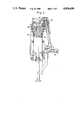
- FIG. 1is a cross-sectional view through a driving tool according to the invention.
- FIG. 2shows a view of the driving tool according to FIG. 1 in the direction of arrow 2 while only a small portion is shown.
- FIG. 3is a cross-sectional view along line 3--3 of FIG. 1.
- FIG. 4shows a cross section of a driving tool according to the invention having a different control valve.
- the driving tool shown in FIG. 1comprises a cylindrical portion 10, a mouth tool 11 below the cylindrical portion, a gripping portion 12 mounted to the cylindrical portion 10 and a magazine 13 between the mouth tool 11 and an extension of the gripping portion 12.
- the cylindrical portion 10includes a cylindrical housing 14 consisting of two telescopically arranged sleeves, a cap 16 sealingly closing the upper portion of the housing 14
- a working cylinder 17is arranged within the housing 14. It includes an outer radial flange 18 which sealingly cooperates with the inner wall of housing 14.
- an upper chamber 19is defined as well as a lower chamber 20.
- the lower chamber 20is connected with the interior of the cylinder by lower ports 21 and through upper ports 22.
- a working piston 23is located within the cylinder having a diameter smaller than the inner diameter D2 of the working cylinder.
- a cylindrical driver 24is attached to the working piston 23, the driver extending through an opening of a stop ring 25 at the lower end of cylinder 17.
- the working piston 23is surrounded by a cup-like annular piston 26.
- a relatively thin-walled cylindrical portion of the annular pistoncooperates with a seal 27 of piston 23.
- a portion of the annular piston 26 having a smaller inner diametercooperates with the driver 24 through a seal 29.
- An annular seal 28 on the outer side of annular piston 26sealingly engages the cylindrical wall.
- the inner diameter of the effective area of the upper portion of the annular piston 26is designated with D1 while the diameter of the driver is D3.
- the mass of piston 23 and of driver 24 on the one side and of the annular piston 26 on the other side as well as the diameter of the effective areas of both pistonsare dimensioned such that ##EQU1## wherein A1 is the effective area of the working piston 23, A2 the effective area of the upper portion of the annular piston 26, m1 the mass of working piston 23 and driver 24 and m2 the mass of annular piston 26.
- A1is the effective area of the working piston 23
- A2the effective area of the upper portion of the annular piston 26
- m1the mass of working piston 23 and driver 24 and m2 the mass of annular piston 26.
- a driving-in channel 30is provided which receives each a nail of a nail stripe 32 having an annularly corrugated shank the individual nails 31 for example are held together by a plastic strip 33.
- the nailsare guided in the magazine 13 in a manner known per se.
- a feed means not shownserves for the feeding of the stripe 32 toward the driving-in channel 30.
- the mouth tool 11further is associated with a sensor 34, the function thereof will be described later on.
- a reservoir 35is within the gripping portion 12 and connected to an inlet fitting 36 for a connection with a supply conduit in a manner known per se.
- a trigger lever 37is pivotally supported at the lower side of the gripping portion. It actuates a trigger valve 38 which in turn cooperates with a repetition control valve 39.
- the repetition valveis connected to the annular chamber 19 through a bore 40.
- the annular chamber 19is connected with a space 42 above the working piston 23 in its upper dead point position or below the plug 16, respectively, through a plurality of bores 41.
- the driving tool explainedis operated as follows:
- the not shown preferably pneumatically operating feed meanshas fed a strip 32 as much as the first nail 31 is located within the driving-in channel 30. This operation occurs after a nail 31 has been driven through a hole 43 in the sheet 44 on beam 45 into beam 45.
- the control valve 39effects that the space 42 is connected to the air reservoir 35.
- the working piston 23is moved downwardly.
- the already mentioned proportion of the effective areas and of the massesis such that the annular piston 26 by no means is no more accelerated as the working piston 23. Therefore, the annular piston 26 is pushed by the working piston 23.
- the driving energyis dimensioned such that normally the nail 31 is not driven into the workpiece 45 by one stroke.
- the nail 31is driven in only about a certain amount while the driver 24 and in conjunction therewith the working piston 23 is relatively strongly decelerated and finally stopped.
- the inertial energy of the annular piston 26effects that the annular piston 26 continues its travel downwardly.
- the upper portion of the annular pistondisengages seal 29 of piston 23 and the effective area exposed to the working pressure is enlarged so that annular piston 26 is moving downwardly with a larger acceleration.
- pressurized airmay enter the return chamber through ports 22, the pressurized air then may be supplied to the annular piston 26 through ports 21.
- the annular piston 26is pneumatically returned (in the known manner corresponding to the pneumatic piston return with known driving tools).
- the return stroke of the annular piston 26takes with it the working piston 23 and moves it to its upper dead point position.
- the control valve 39is a repetition valve, i.e. a relief or a venting of the pressure space 42 is followed by a pressurizing step.
- the control valve 39can exert an arbitrary number of pressure strokes onto the working piston 23, the number of the strokes depending on the time how long the trigger lever 37 is actuated. If the working piston 23 has reached its upper dead point position, the control valve 29 effects a further driving-in stroke.
- the shown driving toolthus is a multi-shot-driving tool. Therefore, the operator will actuate the trigger lever 37 as long as he observes or feels that the nail is completely driven in. It has to be mentioned that the control valve is of known design. It is, thus, not necessary to describe its function in more detail.
- FIG. 4shows a further usual design of a repetition valve which is structured as so-called head valve system 60. It can serve also for a pneumatic control of the pressure supply to the pistons 23, 26. Also, this repetition valve is indirectly operated by a trigger lever 61 through a known trigger valve 62. Upon actuation, this repetition valve leads to an alternative pressure supply and pressure relief of the pressure space above the piston arrangement 23, 26 as already explained.
- FIG. 2it can be seen that at the outer portion of the mouth tool 11 a L-like sensor plate 34 is axially displaceably supported, the limitation is achieved by a tab 50 which engages an elongated hole 51 in plate 34.
- the transverse leg of plate 34cooperates with a spring 52 and an actuation rod 53.
- the actuation rodserves for either the mechanical engagement of the trigger valve 38 or the control valve 39 or the indirect cooperation with the not shown pneumatic feed of the nail strip 37.
- the control by means of the sensor 34can be such that the feed means feeds the nail strip 32 about a distance between two nail axes and to feed a nail into the driving-in channel 30 when the sensor 34 is displaced upwardly upon a placement on a workpiece.
- the sensor 34can effect an additional security function in that a triggering by means of the trigger lever 37 is locked.
- the feed meanscan be controlled by other means, e.g. through the trigger lever 37. For example, the feed of a nail can be carried out at that moment, when the operator releases the trigger lever 37 after a multi stroke actuation.
- connection band 33the nail fed into the driving-in channel is held by the connection band 33.
- the nailcannot slide out of the driving-in channel.
- the last nail of a stripcannot be retained in this manner.
- FIG. 3an axial portion of the upper portion of the driving-in channel 30 is confined by a plurality of jaws 55.
- the jawsdiverge upwardly so that upon an unintended initiation driver 24 does not strike against the jaws 55 in case no nail is in the driving-in channel 30, the jaws 55 in a released position have a minimum distance from each other. If a nail 31 is fed into the driving-in channel 30, its head is engaged by the jaws 55. Upon a stroke, the driver 24 engages the nail head and urges it out of the range of the jaws.
- the narrowest cross section between the jaws 55is preferably dimensioned such that the driver 24 may freely pass.
- the jaws 55may be magnetic in order to increase the retaining effect for a nail 31.
Landscapes
- Engineering & Computer Science (AREA)
- Mechanical Engineering (AREA)
- Physics & Mathematics (AREA)
- Fluid Mechanics (AREA)
- Portable Nailing Machines And Staplers (AREA)
- Nozzles (AREA)
Abstract
Description
Claims (7)
Applications Claiming Priority (2)
| Application Number | Priority Date | Filing Date | Title |
|---|---|---|---|
| EP87109438.9 | 1987-07-01 | ||
| EP87109438AEP0297156B1 (en) | 1987-07-01 | 1987-07-01 | Pneumatically operated fastener driving tool |
Publications (1)
| Publication Number | Publication Date |
|---|---|
| US4856696Atrue US4856696A (en) | 1989-08-15 |
Family
ID=8197099
Family Applications (1)
| Application Number | Title | Priority Date | Filing Date |
|---|---|---|---|
| US07/210,235Expired - LifetimeUS4856696A (en) | 1987-07-01 | 1988-06-23 | Pneumatically operated driving tool for fasteners |
Country Status (5)
| Country | Link |
|---|---|
| US (1) | US4856696A (en) |
| EP (1) | EP0297156B1 (en) |
| JP (1) | JP2603109B2 (en) |
| AT (1) | ATE51790T1 (en) |
| DE (1) | DE3762196D1 (en) |
Cited By (23)
| Publication number | Priority date | Publication date | Assignee | Title |
|---|---|---|---|---|
| US5251371A (en)* | 1992-10-20 | 1993-10-12 | Powers Jack D | T-lock shingle attachment for pneumatic nailers |
| US5579975A (en)* | 1995-04-19 | 1996-12-03 | Senco Products, Inc. | Fastener driving tool for locating a pre-existing through hole in a workpiece and driving a fastener therethrough |
| US5803338A (en)* | 1996-11-26 | 1998-09-08 | Senco Products, Inc. | Fastener driving tool for locating a pre-existing hole in a first workpiece and driving a fastener therethrough into a second workpiece |
| USD410182S (en) | 1997-12-31 | 1999-05-25 | Porter-Cable Corporation | Internal combustion fastener driving tool |
| US6006704A (en)* | 1997-12-31 | 1999-12-28 | Porter-Cable Corporation | Internal combustion fastener driving tool fuel metering system |
| US6016946A (en)* | 1997-12-31 | 2000-01-25 | Porter-Cable Corporation | Internal combustion fastener driving tool shuttle valve |
| US6041603A (en)* | 1997-12-31 | 2000-03-28 | Porter-Cable Corporation | Internal combustion fastener driving tool accelerator plate |
| US6045024A (en)* | 1997-12-31 | 2000-04-04 | Porter-Cable Corporation | Internal combustion fastener driving tool intake reed valve |
| US6158643A (en)* | 1997-12-31 | 2000-12-12 | Porter-Cable Corporation | Internal combustion fastener driving tool piston and piston ring |
| US6260519B1 (en)* | 1997-12-31 | 2001-07-17 | Porter-Cable Corporation | Internal combustion fastener driving tool accelerator plate |
| US20040020964A1 (en)* | 2002-07-30 | 2004-02-05 | Yun-Chung Lee | Rotary cover head of nail gun |
| US20040020965A1 (en)* | 2002-04-05 | 2004-02-05 | Stanley Fastening Systems, L.P. | Pneumatic tool with as-cast air signal passage |
| US20040108354A1 (en)* | 2002-08-09 | 2004-06-10 | Mark Burlingame | Staple gun apparatus for attaching tab |
| US20050145668A1 (en)* | 2003-08-06 | 2005-07-07 | Mark Burlingame | Staple gun apparatus for attaching tab |
| US20050263559A1 (en)* | 2004-05-25 | 2005-12-01 | Hagan Todd A | Fastening tool with automatic feeding of wire-collated fasteners |
| US20060118596A1 (en)* | 2004-12-03 | 2006-06-08 | Wojcicki Andrzej R | Magazine for wired-collated fasteners with automatic loading |
| US20060208027A1 (en)* | 2005-03-16 | 2006-09-21 | Hagan Todd A | Coil nail spreader |
| US20070175942A1 (en)* | 2003-04-04 | 2007-08-02 | Stanley Fastening Systems, L.P. | Pneumatic tool with as-cast air signal passage |
| US20090114697A1 (en)* | 2004-12-03 | 2009-05-07 | Black & Decker Inc. | Magazine for wired-collated fasteners with automatic loading |
| US20090166393A1 (en)* | 2007-02-01 | 2009-07-02 | Black & Decker Inc. | Multistage solenoid fastening device |
| US10654154B2 (en) | 2014-03-27 | 2020-05-19 | Techtronic Power Tools Technology Limited | Powered fastener driver and operating method thereof |
| US11098478B2 (en) | 2015-07-09 | 2021-08-24 | Simpson Strong-Tie Company Inc. | Fastening and alignment member |
| US11110575B2 (en) | 2019-01-31 | 2021-09-07 | Gary Desch | Combination nail dowel gun |
Families Citing this family (7)
| Publication number | Priority date | Publication date | Assignee | Title |
|---|---|---|---|---|
| FR2661353B1 (en)* | 1990-04-27 | 1992-08-07 | Sofragraf Ind | PNEUMATIC NAILING APPARATUS. |
| US5069340A (en)* | 1991-03-05 | 1991-12-03 | Illinois Tool Works Inc. | Strip of collated fasteners for fastener-driving tool |
| JPH07156078A (en)* | 1993-12-03 | 1995-06-20 | Kanematsu Nnk Corp | Fastener striking tool |
| US5733085A (en)* | 1996-08-06 | 1998-03-31 | Illinois Tool Works, Inc. | Fastener assembly and adhesive composition |
| US5931622A (en)* | 1997-10-07 | 1999-08-03 | Illinois Tool Works Inc. | Fastener assembly with lateral end extension |
| US5836732A (en)* | 1997-10-07 | 1998-11-17 | Illinois Tool Works, Inc. | Fastener assembly |
| KR20030017281A (en)* | 2001-09-21 | 2003-03-03 | 신구성 | Automatic nailing apparatus |
Citations (3)
| Publication number | Priority date | Publication date | Assignee | Title |
|---|---|---|---|---|
| US3434643A (en)* | 1966-05-02 | 1969-03-25 | Fastener Corp | Fastener driving apparatus |
| US4003417A (en)* | 1975-07-28 | 1977-01-18 | Leroy Cornwell | Self locking and unlocking clamp for automatic fastener driving tools |
| US4389012A (en)* | 1981-04-22 | 1983-06-21 | Duo-Fast Corporation | Fastener tool loading assembly |
Family Cites Families (4)
| Publication number | Priority date | Publication date | Assignee | Title |
|---|---|---|---|---|
| US3552270A (en)* | 1967-07-13 | 1971-01-05 | Wilfried Lange | Pneumatic stapler device |
| US3776444A (en)* | 1971-06-21 | 1973-12-04 | Trw Inc | Loop fastener gun assembly |
| US4436237A (en)* | 1981-11-16 | 1984-03-13 | Senco Products, Inc. | Automatic firing system for pneumatic tools |
| EP0205633B1 (en)* | 1985-06-21 | 1988-01-27 | Joh. Friedrich Behrens AG | Valve assembly |
- 1987
- 1987-07-01ATAT87109438Tpatent/ATE51790T1/enactive
- 1987-07-01EPEP87109438Apatent/EP0297156B1/ennot_activeExpired - Lifetime
- 1987-07-01DEDE8787109438Tpatent/DE3762196D1/ennot_activeExpired - Lifetime
- 1988
- 1988-06-23USUS07/210,235patent/US4856696A/ennot_activeExpired - Lifetime
- 1988-06-30JPJP63164835Apatent/JP2603109B2/ennot_activeExpired - Lifetime
Patent Citations (3)
| Publication number | Priority date | Publication date | Assignee | Title |
|---|---|---|---|---|
| US3434643A (en)* | 1966-05-02 | 1969-03-25 | Fastener Corp | Fastener driving apparatus |
| US4003417A (en)* | 1975-07-28 | 1977-01-18 | Leroy Cornwell | Self locking and unlocking clamp for automatic fastener driving tools |
| US4389012A (en)* | 1981-04-22 | 1983-06-21 | Duo-Fast Corporation | Fastener tool loading assembly |
Cited By (38)
| Publication number | Priority date | Publication date | Assignee | Title |
|---|---|---|---|---|
| US5251371A (en)* | 1992-10-20 | 1993-10-12 | Powers Jack D | T-lock shingle attachment for pneumatic nailers |
| US5579975A (en)* | 1995-04-19 | 1996-12-03 | Senco Products, Inc. | Fastener driving tool for locating a pre-existing through hole in a workpiece and driving a fastener therethrough |
| US5803338A (en)* | 1996-11-26 | 1998-09-08 | Senco Products, Inc. | Fastener driving tool for locating a pre-existing hole in a first workpiece and driving a fastener therethrough into a second workpiece |
| US6158643A (en)* | 1997-12-31 | 2000-12-12 | Porter-Cable Corporation | Internal combustion fastener driving tool piston and piston ring |
| US6016946A (en)* | 1997-12-31 | 2000-01-25 | Porter-Cable Corporation | Internal combustion fastener driving tool shuttle valve |
| US6041603A (en)* | 1997-12-31 | 2000-03-28 | Porter-Cable Corporation | Internal combustion fastener driving tool accelerator plate |
| US6045024A (en)* | 1997-12-31 | 2000-04-04 | Porter-Cable Corporation | Internal combustion fastener driving tool intake reed valve |
| USD410182S (en) | 1997-12-31 | 1999-05-25 | Porter-Cable Corporation | Internal combustion fastener driving tool |
| US6260519B1 (en)* | 1997-12-31 | 2001-07-17 | Porter-Cable Corporation | Internal combustion fastener driving tool accelerator plate |
| US6006704A (en)* | 1997-12-31 | 1999-12-28 | Porter-Cable Corporation | Internal combustion fastener driving tool fuel metering system |
| US7204402B2 (en) | 2002-04-05 | 2007-04-17 | Stanley Fastening Systems, L.P. | Pneumatic tool with as-cast air signal passage |
| US20040020965A1 (en)* | 2002-04-05 | 2004-02-05 | Stanley Fastening Systems, L.P. | Pneumatic tool with as-cast air signal passage |
| US20040020964A1 (en)* | 2002-07-30 | 2004-02-05 | Yun-Chung Lee | Rotary cover head of nail gun |
| US6763990B2 (en)* | 2002-07-30 | 2004-07-20 | Yun-Chung Lee | Rotary cover head of nail gun |
| US6834731B2 (en) | 2002-08-09 | 2004-12-28 | Columbia River Staple & Lumber Wrap, Inc. | Staple gun apparatus for attaching tab |
| US20040108354A1 (en)* | 2002-08-09 | 2004-06-10 | Mark Burlingame | Staple gun apparatus for attaching tab |
| US20070175942A1 (en)* | 2003-04-04 | 2007-08-02 | Stanley Fastening Systems, L.P. | Pneumatic tool with as-cast air signal passage |
| US7090109B2 (en) | 2003-08-06 | 2006-08-15 | Columbia River Staple & Lumber Wrap, Inc. | Staple gun apparatus for attaching tab |
| US20050145668A1 (en)* | 2003-08-06 | 2005-07-07 | Mark Burlingame | Staple gun apparatus for attaching tab |
| US7699201B2 (en) | 2004-05-25 | 2010-04-20 | Black & Decker Inc. | Fastening tool with automatic feeding of wire-collated fasteners |
| US8051919B2 (en) | 2004-05-25 | 2011-11-08 | Black & Decker Inc. | Fastening tool with automatic feeding of wire-collated fasteners |
| US20050263559A1 (en)* | 2004-05-25 | 2005-12-01 | Hagan Todd A | Fastening tool with automatic feeding of wire-collated fasteners |
| US7455207B2 (en) | 2004-12-03 | 2008-11-25 | Black & Decker Inc. | Magazine for wired-collated fasteners with automatic loading |
| US20060118596A1 (en)* | 2004-12-03 | 2006-06-08 | Wojcicki Andrzej R | Magazine for wired-collated fasteners with automatic loading |
| US20070125824A1 (en)* | 2004-12-03 | 2007-06-07 | Wojcicki Andrzej R | Magazine for wired-collated fasteners with automatic loading |
| US20090114697A1 (en)* | 2004-12-03 | 2009-05-07 | Black & Decker Inc. | Magazine for wired-collated fasteners with automatic loading |
| US7866521B2 (en) | 2004-12-03 | 2011-01-11 | Black & Decker Inc. | Magazine for wired-collated fasteners with automatic loading |
| US7137186B2 (en) | 2004-12-03 | 2006-11-21 | Black & Decker Inc. | Magazine for wired-collated fasteners with automatic loading |
| US7950556B2 (en) | 2005-03-16 | 2011-05-31 | Black & Decker Inc. | Coil nail spreader |
| US20060208027A1 (en)* | 2005-03-16 | 2006-09-21 | Hagan Todd A | Coil nail spreader |
| US20090166393A1 (en)* | 2007-02-01 | 2009-07-02 | Black & Decker Inc. | Multistage solenoid fastening device |
| US7665540B2 (en) | 2007-02-01 | 2010-02-23 | Black & Decker Inc. | Multistage solenoid fastening device |
| US7913890B2 (en) | 2007-02-01 | 2011-03-29 | Black & Decker Inc. | Multistage solenoid fastening device |
| US10654154B2 (en) | 2014-03-27 | 2020-05-19 | Techtronic Power Tools Technology Limited | Powered fastener driver and operating method thereof |
| US10759029B2 (en) | 2014-03-27 | 2020-09-01 | Techtronic Power Tools Technology Limited | Powered fastener driver and operating method thereof |
| US11098478B2 (en) | 2015-07-09 | 2021-08-24 | Simpson Strong-Tie Company Inc. | Fastening and alignment member |
| US11965329B2 (en) | 2015-07-09 | 2024-04-23 | Simpson Strong-Tie Company, Inc. | Fastening and alignment member |
| US11110575B2 (en) | 2019-01-31 | 2021-09-07 | Gary Desch | Combination nail dowel gun |
Also Published As
| Publication number | Publication date |
|---|---|
| EP0297156B1 (en) | 1990-04-11 |
| JPH0192075A (en) | 1989-04-11 |
| DE3762196D1 (en) | 1990-05-17 |
| JP2603109B2 (en) | 1997-04-23 |
| ATE51790T1 (en) | 1990-04-15 |
| EP0297156A1 (en) | 1989-01-04 |
Similar Documents
| Publication | Publication Date | Title |
|---|---|---|
| US4856696A (en) | Pneumatically operated driving tool for fasteners | |
| US4040554A (en) | Pneumatic apparatus | |
| US6095392A (en) | Pneumatic nailer including safety trigger for disabling/enabling operation | |
| US5131579A (en) | Nailing machine | |
| US20220219303A1 (en) | Reversion trigger for combustion-powered fastener-driving tool | |
| US3774293A (en) | Fastener driving tool | |
| US5485946A (en) | Release locking means of a driving tool for fasteners | |
| US3661312A (en) | Detection and cutoff mechanism for power driven devices | |
| JP4145968B2 (en) | Combustion power tool with internal combustion power source | |
| US5135152A (en) | Pneumatic fastener driving tool | |
| US3893610A (en) | Pneumatic device for driving headed objects | |
| CA2694967C (en) | Actuator pin guide for a fastener driving tool | |
| US3606128A (en) | Percussion machine for fasteners | |
| KR101473351B1 (en) | A nosepiece of a fastener-driving tool equipped with a fastener magazine | |
| SE441343B (en) | nailer | |
| US3954176A (en) | Nail carrying structures | |
| US3969988A (en) | Arresting device for impact drive tools | |
| US3927459A (en) | Process for feeding and driving nails | |
| EP0284682A3 (en) | Punch gun | |
| US4726504A (en) | Portable self-piercing riveting apparatus | |
| EP0796703A2 (en) | Magnetic biased driving element for a fastener driving tool | |
| US3952398A (en) | Process for pneumatically impelling a hammer to drive a nail into a substrate | |
| US3023413A (en) | Portable, air-operated, magazine-fed nailing machine | |
| US4184357A (en) | Fastening with two-piece fasteners | |
| USRE27101E (en) | Fastener driving apparatus |
Legal Events
| Date | Code | Title | Description |
|---|---|---|---|
| AS | Assignment | Owner name:JOH. FRIEDRICH BEHRENS AG, BOGENSTRASSE 43-45, 207 Free format text:ASSIGNMENT OF ASSIGNORS INTEREST.;ASSIGNOR:VON SELD, SIGURD;REEL/FRAME:004932/0365 Effective date:19880811 | |
| STCF | Information on status: patent grant | Free format text:PATENTED CASE | |
| FEPP | Fee payment procedure | Free format text:PAYOR NUMBER ASSIGNED (ORIGINAL EVENT CODE: ASPN); ENTITY STATUS OF PATENT OWNER: SMALL ENTITY | |
| FEPP | Fee payment procedure | Free format text:PAYER NUMBER DE-ASSIGNED (ORIGINAL EVENT CODE: RMPN); ENTITY STATUS OF PATENT OWNER: SMALL ENTITY | |
| REMI | Maintenance fee reminder mailed | ||
| FPAY | Fee payment | Year of fee payment:4 | |
| SULP | Surcharge for late payment | ||
| AS | Assignment | Owner name:SELD, SIGURD V., GERMANY Free format text:ASSIGNMENT OF ASSIGNORS INTEREST;ASSIGNOR:JOH. FRIEDRICH BEHRENS AG;REEL/FRAME:006721/0561 Effective date:19930902 | |
| FEPP | Fee payment procedure | Free format text:PAT HOLDER CLAIMS SMALL ENTITY STATUS - SMALL BUSINESS (ORIGINAL EVENT CODE: SM02); ENTITY STATUS OF PATENT OWNER: SMALL ENTITY | |
| FPAY | Fee payment | Year of fee payment:8 | |
| FPAY | Fee payment | Year of fee payment:12 |