US4856363A - Parking brake assembly - Google Patents
Parking brake assemblyDownload PDFInfo
- Publication number
- US4856363A US4856363AUS07/154,266US15426688AUS4856363AUS 4856363 AUS4856363 AUS 4856363AUS 15426688 AUS15426688 AUS 15426688AUS 4856363 AUS4856363 AUS 4856363A
- Authority
- US
- United States
- Prior art keywords
- pawl
- axle
- sleeve
- handle
- assembly
- Prior art date
- Legal status (The legal status is an assumption and is not a legal conclusion. Google has not performed a legal analysis and makes no representation as to the accuracy of the status listed.)
- Expired - Fee Related
Links
- 230000007246mechanismEffects0.000description4
- 230000000712assemblyEffects0.000description2
- 238000000429assemblyMethods0.000description2
- 229910000831SteelInorganic materials0.000description1
- 125000006850spacer groupChemical group0.000description1
- 239000010959steelSubstances0.000description1
Images


Classifications
- B—PERFORMING OPERATIONS; TRANSPORTING
- B60—VEHICLES IN GENERAL
- B60T—VEHICLE BRAKE CONTROL SYSTEMS OR PARTS THEREOF; BRAKE CONTROL SYSTEMS OR PARTS THEREOF, IN GENERAL; ARRANGEMENT OF BRAKING ELEMENTS ON VEHICLES IN GENERAL; PORTABLE DEVICES FOR PREVENTING UNWANTED MOVEMENT OF VEHICLES; VEHICLE MODIFICATIONS TO FACILITATE COOLING OF BRAKES
- B60T7/00—Brake-action initiating means
- B60T7/02—Brake-action initiating means for personal initiation
- B60T7/08—Brake-action initiating means for personal initiation hand actuated
- B60T7/10—Disposition of hand control
- B60T7/102—Disposition of hand control by means of a tilting lever
- B60T7/104—Disposition of hand control by means of a tilting lever with a locking mechanism
- Y—GENERAL TAGGING OF NEW TECHNOLOGICAL DEVELOPMENTS; GENERAL TAGGING OF CROSS-SECTIONAL TECHNOLOGIES SPANNING OVER SEVERAL SECTIONS OF THE IPC; TECHNICAL SUBJECTS COVERED BY FORMER USPC CROSS-REFERENCE ART COLLECTIONS [XRACs] AND DIGESTS
- Y10—TECHNICAL SUBJECTS COVERED BY FORMER USPC
- Y10T—TECHNICAL SUBJECTS COVERED BY FORMER US CLASSIFICATION
- Y10T74/00—Machine element or mechanism
- Y10T74/20—Control lever and linkage systems
- Y10T74/20576—Elements
- Y10T74/20582—Levers
- Y10T74/20612—Hand
- Y—GENERAL TAGGING OF NEW TECHNOLOGICAL DEVELOPMENTS; GENERAL TAGGING OF CROSS-SECTIONAL TECHNOLOGIES SPANNING OVER SEVERAL SECTIONS OF THE IPC; TECHNICAL SUBJECTS COVERED BY FORMER USPC CROSS-REFERENCE ART COLLECTIONS [XRACs] AND DIGESTS
- Y10—TECHNICAL SUBJECTS COVERED BY FORMER USPC
- Y10T—TECHNICAL SUBJECTS COVERED BY FORMER US CLASSIFICATION
- Y10T74/00—Machine element or mechanism
- Y10T74/20—Control lever and linkage systems
- Y10T74/20576—Elements
- Y10T74/20636—Detents
- Y10T74/20672—Lever engaging rack
- Y10T74/20684—Lever carried pawl
Definitions
- the field of the inventionrelates to parking brake assemblies for motor vehicles.
- Parking brake assembliesare generally hand or foot operated, and function by displacing a cable connected to a brake mechanism.
- the cableis usually connected to a movable member which may be locked in position by a pawl and ratchet assembly. Releasing the pawl from the ratchet allows the tension to be withdrawn from the cable and the brake to be released.
- a parking brake assemblywhich is simple to operate, has a neat appearance, is light in weight and provides reliability in operation.
- the assemblyincludes a ratchet and pawl locking mechanism which is actuated or deactuated by means of a tube or sleeve mounted to an axle.
- the pawlis operatively connected to the sleeve such that rotation of the sleeve in one direction causes the pawl to pivot into engagement with the ratchet, while rotation in the opposite direction causes the pawl to be released.
- a springis employed to urge the sleeve in the one direction.
- a release rodis connected to the sleeve and to a trigger assembly.
- the release rodcauses the sleeve to rotate against the force of the spring, thereby releasing the pawl from the ratchet.
- the inventionallows the use of a U-shaped handle having a pair of arms, each of which is secured to an axle.
- the axleextends through a mounting bracket to which the ratchet is secured.
- the sleeveis mounted to the axle. Rotation of the axle is permitted in either direction upon disengagement of the pawl.
- a cable connected between a brake mechanism and a mounting member secured to the axleis displaced upon rotation of the axle, thereby allowing the brake to be set or released.
- FIG. 1is a perspective view of a parking brake assembly in accordance with the invention
- FIG. 3is a sectional view taken along line 3--3 of FIG. 2;
- FIG. 4is a sectional view taken along line 4--4 of FIG. 2;
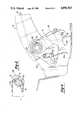
- FIG. 5is an exploded, perspective view of a portion of the parking brake assembly.
- FIG. 6is an enlarged, sectional view of the handle of the parking brake assembly, taken along lines 6--6 of FIG. 1.
- the brake actuating assemblyincludes a mounting bracket 20 including appropriate slots 22 and openings 24, 26 to allow it to be secured to a motor vehicle body.
- a sector 28 including ratchet teethis mounted to the bracket 20 and is immovable with respect thereto.
- An axle 30extends between and is secured to the opposing handle arms 14, 14A. The handle and axle are rotatable as a unit with respect to the bracket 20.
- Three sleeves 32, 34, 36are mounted to the axle. Two of the sleeves 32, 34 are secured to the axle by pins 38 while the third 36, hereinafter referred to as the torque tube, is free to rotate with respect to the axle.
- the torque tube 36 and the first sleeve 32extend between the outside surfaces of the mounting bracket 20 and the respective arms 14, 14A of the handle 12, thereby serving as spacers.
- the torque tube 36includes a pair of projections 48, 50.
- One projection 48extends within the arm 14A of the handle and includes an opening for receiving the end of the release rod 18.
- the second projection 50is located near the opposite end of the torque 36, i.e., near the mounting bracket 20. It is also positioned ninety to one hundred eighty degrees rotationally with respect to the first projection 48.
- the second projection 50includes a pair of openings.
- a coil spring 52is connected between the first of the two openings and the projection 40A extending from the pawl guide.
- An actuator rod 54is connected between the second of the two openings and an opening within the pawl 42.
- a switch 56which forms no part of the present invention, is secured to the sector 28.
- the pawl guide plate 41includes a foot 41A which displaces a switch contact 56A when the handle 12 is rotated to the lowest position to extinguish an indicator light (not shown) when the parking brake is released.
- the handle 12is manually rotatable about an axis defined by the first axle 30.
- the operatorsqueezes handle portion 14B and the trigger 16 to move the trigger into handle recess 14C, thereby causing the rod 18 to rotate the torque tube 36 counterclockwise about its longitudinal axis, as viewed in FIG. 3.
- This rotationcauses the actuator rod 54 to move the pawl 42 about the second axle 46, disengaging it from the sector 28.
- Handle 12may then be lower to a substantially horizontal position, whereupon release of trigger 16 causes the spring 52 to urge the torque tube 30 clockwise. This moves pawl 42 towards an engaging position with the sector 28.
- the brakemay be set by simply rotating the handle 12 towards a vertical position causing pawl 42 to "ratchet” as the angled teeth of sector 28 cam the pawl outwardly against the bias of the spring 52. Release of handle will engage pawl 42 with the teeth of sector 28 in a conventional manner to set the park brake via cable 49.
Landscapes
- Engineering & Computer Science (AREA)
- Transportation (AREA)
- Mechanical Engineering (AREA)
- Braking Elements And Transmission Devices (AREA)
Abstract
Description
Claims (12)
Priority Applications (1)
| Application Number | Priority Date | Filing Date | Title |
|---|---|---|---|
| US07/154,266US4856363A (en) | 1988-02-10 | 1988-02-10 | Parking brake assembly |
Applications Claiming Priority (1)
| Application Number | Priority Date | Filing Date | Title |
|---|---|---|---|
| US07/154,266US4856363A (en) | 1988-02-10 | 1988-02-10 | Parking brake assembly |
Publications (1)
| Publication Number | Publication Date |
|---|---|
| US4856363Atrue US4856363A (en) | 1989-08-15 |
Family
ID=22550673
Family Applications (1)
| Application Number | Title | Priority Date | Filing Date |
|---|---|---|---|
| US07/154,266Expired - Fee RelatedUS4856363A (en) | 1988-02-10 | 1988-02-10 | Parking brake assembly |
Country Status (1)
| Country | Link |
|---|---|
| US (1) | US4856363A (en) |
Cited By (27)
| Publication number | Priority date | Publication date | Assignee | Title |
|---|---|---|---|---|
| US5753873A (en)* | 1996-02-13 | 1998-05-19 | Dura Automotive Systems, Inc. | Parking brake for a vehicle provided with a self-cleaning ground contactor |
| US6202504B1 (en) | 1999-04-02 | 2001-03-20 | Edmund P. Burkle | Extension handle for emergency or safety brake lever |
| EP1431148A3 (en)* | 2002-12-18 | 2004-08-04 | Adam Opel Ag | Parking brake for a vehicle and vehicle having a parking brake |
| US20070209469A1 (en)* | 2006-02-28 | 2007-09-13 | Martin Otto | Actuating device for a parking brake of a motor vehicle |
| CN101537827B (en)* | 2008-03-19 | 2011-04-06 | 财团法人车辆研究测试中心 | Drives for parking systems |
| US9068699B2 (en) | 2007-04-19 | 2015-06-30 | Brandeis University | Manipulation of fluids, fluid components and reactions in microfluidic systems |
| US9228229B2 (en) | 2010-02-12 | 2016-01-05 | Raindance Technologies, Inc. | Digital analyte analysis |
| US9328344B2 (en) | 2006-01-11 | 2016-05-03 | Raindance Technologies, Inc. | Microfluidic devices and methods of use in the formation and control of nanoreactors |
| US9366632B2 (en) | 2010-02-12 | 2016-06-14 | Raindance Technologies, Inc. | Digital analyte analysis |
| US9440232B2 (en) | 2007-02-06 | 2016-09-13 | Raindance Technologies, Inc. | Manipulation of fluids and reactions in microfluidic systems |
| US9562837B2 (en) | 2006-05-11 | 2017-02-07 | Raindance Technologies, Inc. | Systems for handling microfludic droplets |
| US10351905B2 (en) | 2010-02-12 | 2019-07-16 | Bio-Rad Laboratories, Inc. | Digital analyte analysis |
| US10639597B2 (en) | 2006-05-11 | 2020-05-05 | Bio-Rad Laboratories, Inc. | Microfluidic devices |
| US10647981B1 (en) | 2015-09-08 | 2020-05-12 | Bio-Rad Laboratories, Inc. | Nucleic acid library generation methods and compositions |
| US11077415B2 (en) | 2011-02-11 | 2021-08-03 | Bio-Rad Laboratories, Inc. | Methods for forming mixed droplets |
| US11168353B2 (en) | 2011-02-18 | 2021-11-09 | Bio-Rad Laboratories, Inc. | Compositions and methods for molecular labeling |
| US11174509B2 (en) | 2013-12-12 | 2021-11-16 | Bio-Rad Laboratories, Inc. | Distinguishing rare variations in a nucleic acid sequence from a sample |
| US11187702B2 (en) | 2003-03-14 | 2021-11-30 | Bio-Rad Laboratories, Inc. | Enzyme quantification |
| US11390917B2 (en) | 2010-02-12 | 2022-07-19 | Bio-Rad Laboratories, Inc. | Digital analyte analysis |
| US11511242B2 (en) | 2008-07-18 | 2022-11-29 | Bio-Rad Laboratories, Inc. | Droplet libraries |
| US11635427B2 (en) | 2010-09-30 | 2023-04-25 | Bio-Rad Laboratories, Inc. | Sandwich assays in droplets |
| US11786872B2 (en) | 2004-10-08 | 2023-10-17 | United Kingdom Research And Innovation | Vitro evolution in microfluidic systems |
| US11898193B2 (en) | 2011-07-20 | 2024-02-13 | Bio-Rad Laboratories, Inc. | Manipulating droplet size |
| US11901041B2 (en) | 2013-10-04 | 2024-02-13 | Bio-Rad Laboratories, Inc. | Digital analysis of nucleic acid modification |
| US12038438B2 (en) | 2008-07-18 | 2024-07-16 | Bio-Rad Laboratories, Inc. | Enzyme quantification |
| US12194976B1 (en)* | 2023-09-11 | 2025-01-14 | Robert F Trepanier | Safety parking brake system for campers and all tow trailers |
| US12352673B2 (en) | 2009-03-23 | 2025-07-08 | Bio-Rad Laboratories, Inc. | Manipulation of microfluidic droplets |
Citations (13)
| Publication number | Priority date | Publication date | Assignee | Title |
|---|---|---|---|---|
| US1823695A (en)* | 1927-12-16 | 1931-09-15 | Packard Motor Car Co | Motor vehicle |
| US2467557A (en)* | 1946-05-20 | 1949-04-19 | Houdaille Hershey Corp | Brake lever structure |
| US2816456A (en)* | 1952-10-17 | 1957-12-17 | Massey Harris Ferguson Ltd | Brake latch mechanism |
| US2893262A (en)* | 1954-01-11 | 1959-07-07 | Chicago Forging & Mfg Co | Emergency brakes and releases therefor |
| US2986046A (en)* | 1958-07-11 | 1961-05-30 | Mount Clemens Metal Products C | Brake lever assembly |
| US3273418A (en)* | 1963-12-12 | 1966-09-20 | Elmer F Ellis | Vehicle parking brake control |
| US3511107A (en)* | 1968-02-16 | 1970-05-12 | Otsukakoki Kk | Parking brake control devices |
| DE2546111A1 (en)* | 1975-10-15 | 1977-04-28 | Geb Winkelstroeter Es Schwarte | Compact handbrake lever on transmission tunnel - with handgrip across tunnel and pivotted levers straddling tunnel |
| US4512210A (en)* | 1982-09-30 | 1985-04-23 | Donovan Wire & Iron | Parking brake lever assembly |
| US4515036A (en)* | 1983-04-25 | 1985-05-07 | Gulf & Western Manufacturing Company | Vehicle parking brake self-adjusting control mechanism |
| US4570508A (en)* | 1984-06-08 | 1986-02-18 | General Motors Corporation | Multi-stroke parking brake variable ratio apply and release mechanism |
| US4620453A (en)* | 1984-07-13 | 1986-11-04 | Yamaha Hatsudoki Kabushiki Kaisha | Shift control device of vehicular transmission |
| FR2582272A1 (en)* | 1985-05-21 | 1986-11-28 | Renault | Handbrake control lever |
- 1988
- 1988-02-10USUS07/154,266patent/US4856363A/ennot_activeExpired - Fee Related
Patent Citations (13)
| Publication number | Priority date | Publication date | Assignee | Title |
|---|---|---|---|---|
| US1823695A (en)* | 1927-12-16 | 1931-09-15 | Packard Motor Car Co | Motor vehicle |
| US2467557A (en)* | 1946-05-20 | 1949-04-19 | Houdaille Hershey Corp | Brake lever structure |
| US2816456A (en)* | 1952-10-17 | 1957-12-17 | Massey Harris Ferguson Ltd | Brake latch mechanism |
| US2893262A (en)* | 1954-01-11 | 1959-07-07 | Chicago Forging & Mfg Co | Emergency brakes and releases therefor |
| US2986046A (en)* | 1958-07-11 | 1961-05-30 | Mount Clemens Metal Products C | Brake lever assembly |
| US3273418A (en)* | 1963-12-12 | 1966-09-20 | Elmer F Ellis | Vehicle parking brake control |
| US3511107A (en)* | 1968-02-16 | 1970-05-12 | Otsukakoki Kk | Parking brake control devices |
| DE2546111A1 (en)* | 1975-10-15 | 1977-04-28 | Geb Winkelstroeter Es Schwarte | Compact handbrake lever on transmission tunnel - with handgrip across tunnel and pivotted levers straddling tunnel |
| US4512210A (en)* | 1982-09-30 | 1985-04-23 | Donovan Wire & Iron | Parking brake lever assembly |
| US4515036A (en)* | 1983-04-25 | 1985-05-07 | Gulf & Western Manufacturing Company | Vehicle parking brake self-adjusting control mechanism |
| US4570508A (en)* | 1984-06-08 | 1986-02-18 | General Motors Corporation | Multi-stroke parking brake variable ratio apply and release mechanism |
| US4620453A (en)* | 1984-07-13 | 1986-11-04 | Yamaha Hatsudoki Kabushiki Kaisha | Shift control device of vehicular transmission |
| FR2582272A1 (en)* | 1985-05-21 | 1986-11-28 | Renault | Handbrake control lever |
Cited By (51)
| Publication number | Priority date | Publication date | Assignee | Title |
|---|---|---|---|---|
| US5753873A (en)* | 1996-02-13 | 1998-05-19 | Dura Automotive Systems, Inc. | Parking brake for a vehicle provided with a self-cleaning ground contactor |
| US6202504B1 (en) | 1999-04-02 | 2001-03-20 | Edmund P. Burkle | Extension handle for emergency or safety brake lever |
| EP1431148A3 (en)* | 2002-12-18 | 2004-08-04 | Adam Opel Ag | Parking brake for a vehicle and vehicle having a parking brake |
| US11187702B2 (en) | 2003-03-14 | 2021-11-30 | Bio-Rad Laboratories, Inc. | Enzyme quantification |
| US11786872B2 (en) | 2004-10-08 | 2023-10-17 | United Kingdom Research And Innovation | Vitro evolution in microfluidic systems |
| US9534216B2 (en) | 2006-01-11 | 2017-01-03 | Raindance Technologies, Inc. | Microfluidic devices and methods of use in the formation and control of nanoreactors |
| US12146134B2 (en) | 2006-01-11 | 2024-11-19 | Bio-Rad Laboratories, Inc. | Microfluidic devices and methods of use in the formation and control of nanoreactors |
| US9328344B2 (en) | 2006-01-11 | 2016-05-03 | Raindance Technologies, Inc. | Microfluidic devices and methods of use in the formation and control of nanoreactors |
| US9410151B2 (en) | 2006-01-11 | 2016-08-09 | Raindance Technologies, Inc. | Microfluidic devices and methods of use in the formation and control of nanoreactors |
| US8464605B2 (en)* | 2006-02-28 | 2013-06-18 | Ford Global Technologies, Llc | Actuating device for a parking brake of a motor vehicle |
| US20070209469A1 (en)* | 2006-02-28 | 2007-09-13 | Martin Otto | Actuating device for a parking brake of a motor vehicle |
| US12091710B2 (en) | 2006-05-11 | 2024-09-17 | Bio-Rad Laboratories, Inc. | Systems and methods for handling microfluidic droplets |
| US9562837B2 (en) | 2006-05-11 | 2017-02-07 | Raindance Technologies, Inc. | Systems for handling microfludic droplets |
| US12337287B2 (en) | 2006-05-11 | 2025-06-24 | Bio-Rad Laboratories, Inc. | Microfluidic devices |
| US10639597B2 (en) | 2006-05-11 | 2020-05-05 | Bio-Rad Laboratories, Inc. | Microfluidic devices |
| US11351510B2 (en) | 2006-05-11 | 2022-06-07 | Bio-Rad Laboratories, Inc. | Microfluidic devices |
| US9440232B2 (en) | 2007-02-06 | 2016-09-13 | Raindance Technologies, Inc. | Manipulation of fluids and reactions in microfluidic systems |
| US11819849B2 (en) | 2007-02-06 | 2023-11-21 | Brandeis University | Manipulation of fluids and reactions in microfluidic systems |
| US10603662B2 (en) | 2007-02-06 | 2020-03-31 | Brandeis University | Manipulation of fluids and reactions in microfluidic systems |
| US10960397B2 (en) | 2007-04-19 | 2021-03-30 | President And Fellows Of Harvard College | Manipulation of fluids, fluid components and reactions in microfluidic systems |
| US10675626B2 (en) | 2007-04-19 | 2020-06-09 | President And Fellows Of Harvard College | Manipulation of fluids, fluid components and reactions in microfluidic systems |
| US10357772B2 (en) | 2007-04-19 | 2019-07-23 | President And Fellows Of Harvard College | Manipulation of fluids, fluid components and reactions in microfluidic systems |
| US9068699B2 (en) | 2007-04-19 | 2015-06-30 | Brandeis University | Manipulation of fluids, fluid components and reactions in microfluidic systems |
| US11224876B2 (en) | 2007-04-19 | 2022-01-18 | Brandeis University | Manipulation of fluids, fluid components and reactions in microfluidic systems |
| US11618024B2 (en) | 2007-04-19 | 2023-04-04 | President And Fellows Of Harvard College | Manipulation of fluids, fluid components and reactions in microfluidic systems |
| CN101537827B (en)* | 2008-03-19 | 2011-04-06 | 财团法人车辆研究测试中心 | Drives for parking systems |
| US11534727B2 (en) | 2008-07-18 | 2022-12-27 | Bio-Rad Laboratories, Inc. | Droplet libraries |
| US12038438B2 (en) | 2008-07-18 | 2024-07-16 | Bio-Rad Laboratories, Inc. | Enzyme quantification |
| US11596908B2 (en) | 2008-07-18 | 2023-03-07 | Bio-Rad Laboratories, Inc. | Droplet libraries |
| US11511242B2 (en) | 2008-07-18 | 2022-11-29 | Bio-Rad Laboratories, Inc. | Droplet libraries |
| US12352673B2 (en) | 2009-03-23 | 2025-07-08 | Bio-Rad Laboratories, Inc. | Manipulation of microfluidic droplets |
| US9366632B2 (en) | 2010-02-12 | 2016-06-14 | Raindance Technologies, Inc. | Digital analyte analysis |
| US11390917B2 (en) | 2010-02-12 | 2022-07-19 | Bio-Rad Laboratories, Inc. | Digital analyte analysis |
| US11254968B2 (en) | 2010-02-12 | 2022-02-22 | Bio-Rad Laboratories, Inc. | Digital analyte analysis |
| US10808279B2 (en) | 2010-02-12 | 2020-10-20 | Bio-Rad Laboratories, Inc. | Digital analyte analysis |
| US10351905B2 (en) | 2010-02-12 | 2019-07-16 | Bio-Rad Laboratories, Inc. | Digital analyte analysis |
| US9228229B2 (en) | 2010-02-12 | 2016-01-05 | Raindance Technologies, Inc. | Digital analyte analysis |
| US11635427B2 (en) | 2010-09-30 | 2023-04-25 | Bio-Rad Laboratories, Inc. | Sandwich assays in droplets |
| US11077415B2 (en) | 2011-02-11 | 2021-08-03 | Bio-Rad Laboratories, Inc. | Methods for forming mixed droplets |
| US11168353B2 (en) | 2011-02-18 | 2021-11-09 | Bio-Rad Laboratories, Inc. | Compositions and methods for molecular labeling |
| US11965877B2 (en) | 2011-02-18 | 2024-04-23 | Bio-Rad Laboratories, Inc. | Compositions and methods for molecular labeling |
| US11768198B2 (en) | 2011-02-18 | 2023-09-26 | Bio-Rad Laboratories, Inc. | Compositions and methods for molecular labeling |
| US12140590B2 (en) | 2011-02-18 | 2024-11-12 | Bio-Rad Laboratories, Inc. | Compositions and methods for molecular labeling |
| US12140591B2 (en) | 2011-02-18 | 2024-11-12 | Bio-Rad Laboratories, Inc. | Compositions and methods for molecular labeling |
| US11747327B2 (en) | 2011-02-18 | 2023-09-05 | Bio-Rad Laboratories, Inc. | Compositions and methods for molecular labeling |
| US11754499B2 (en) | 2011-06-02 | 2023-09-12 | Bio-Rad Laboratories, Inc. | Enzyme quantification |
| US11898193B2 (en) | 2011-07-20 | 2024-02-13 | Bio-Rad Laboratories, Inc. | Manipulating droplet size |
| US11901041B2 (en) | 2013-10-04 | 2024-02-13 | Bio-Rad Laboratories, Inc. | Digital analysis of nucleic acid modification |
| US11174509B2 (en) | 2013-12-12 | 2021-11-16 | Bio-Rad Laboratories, Inc. | Distinguishing rare variations in a nucleic acid sequence from a sample |
| US10647981B1 (en) | 2015-09-08 | 2020-05-12 | Bio-Rad Laboratories, Inc. | Nucleic acid library generation methods and compositions |
| US12194976B1 (en)* | 2023-09-11 | 2025-01-14 | Robert F Trepanier | Safety parking brake system for campers and all tow trailers |
Similar Documents
| Publication | Publication Date | Title |
|---|---|---|
| US4856363A (en) | Parking brake assembly | |
| US4840388A (en) | Grocery cart | |
| US5953962A (en) | Cable controller | |
| US9109688B2 (en) | Device for controlling a gearbox and a parking brake of a motor vehicle, using a common operating lever | |
| US4854187A (en) | Hand brake assembly for a vehicle | |
| US5211072A (en) | Variable ratio park brake with slack adjust | |
| US2631470A (en) | Straight pull brake lever structure | |
| JP3174180B2 (en) | Steering column assembly | |
| JP2527612B2 (en) | Operating device for parking brake | |
| US2543509A (en) | Straight pull brake lever structure | |
| US5546828A (en) | Parking brake | |
| US7219918B2 (en) | Stroller having a brake device | |
| US4977789A (en) | Vehicle shift lever assembly | |
| US6986531B2 (en) | Steering column linkage tilt lever | |
| JPS611563A (en) | Parking-brake gear | |
| KR101776569B1 (en) | Parking brake apparatus for a vehicle | |
| US2188281A (en) | Brake control mechanism | |
| GB1580005A (en) | Hand-operable lever assemblies | |
| JPH0798477B2 (en) | Parking brake operating device | |
| US2899838A (en) | Delayed action brake release s | |
| JPS6313970Y2 (en) | ||
| US2739672A (en) | Hand brake with power assist | |
| US2903907A (en) | Parking brake for vehicles | |
| JP4050809B2 (en) | Manual brake device | |
| JP2585776B2 (en) | Foot-operated parking brake device |
Legal Events
| Date | Code | Title | Description |
|---|---|---|---|
| AS | Assignment | Owner name:WICKES MANUFACTURING COMPANY, 26261 EVERGREEN ROAD Free format text:ASSIGNMENT OF ASSIGNORS INTEREST.;ASSIGNORS:LA ROCCA, WILLIAM J.;TRUSH, DAVID M.;REEL/FRAME:004836/0563 Effective date:19880205 Owner name:WICKES MANUFACTURING COMPANY, A CORP. OF DE., MIC Free format text:ASSIGNMENT OF ASSIGNORS INTEREST;ASSIGNORS:LA ROCCA, WILLIAM J.;TRUSH, DAVID M.;REEL/FRAME:004836/0563 Effective date:19880205 | |
| AS | Assignment | Owner name:DURA MECHANICAL COMPONENTS, INC., 1708 NORTHWOOD, Free format text:ASSIGNMENT OF ASSIGNORS INTEREST.;ASSIGNOR:WICKES MANUFACTURING COMPANY, A CORP. OF DE;REEL/FRAME:005578/0087 Effective date:19901130 | |
| AS | Assignment | Owner name:CONTINENTAL BANK N.A., 231 SOUTH LASALLE STREET, C Free format text:SECURITY INTEREST;ASSIGNOR:DURA MECHANICAL COMPONENTS, INC., A CORP. OF DELAWARE;REEL/FRAME:005620/0786 Effective date:19901130 | |
| REMI | Maintenance fee reminder mailed | ||
| LAPS | Lapse for failure to pay maintenance fees | ||
| FP | Lapsed due to failure to pay maintenance fee | Effective date:19930815 | |
| AS | Assignment | Owner name:DURA MECHANICAL COMPONENTS, INC., MICHIGAN Free format text:RELEASE OF COLLATERAL PATENT SECURITY AGREEMENT;ASSIGNOR:CONTINENTAL BANK, AN ILLINOIS BANKING CORP.(F/K/A CONTINENTAL BANK N.A., A NATIONAL BANKING ASSOCIATION);REEL/FRAME:007160/0019 Effective date:19940831 | |
| AS | Assignment | Owner name:CONTINENTAL BANK, ILLINOIS Free format text:COLLATERAL PATENT SECURITY AGREEMENT;ASSIGNOR:DURA AUTOMOTIVE SYSTEMS, INC.;REEL/FRAME:007165/0032 Effective date:19940831 | |
| AS | Assignment | Owner name:BANK OF AMERICA NATIONAL TRUST AND SAVINGS ASSOCIA Free format text:ASSIGNMENT OF ASSIGNORS INTEREST;ASSIGNOR:BANK OF AMERICA ILLINOIS;REEL/FRAME:007541/0888 Effective date:19950711 | |
| AS | Assignment | Owner name:BANK OF AMERICA NATIONAL TRUST AND SAVINGS ASSOCIA Free format text:SECURITY AGREEMENT;ASSIGNOR:DURA OPERATING CORP., F/K/A DURA AUTOMOTIVE SYSTEMS, INC.;REEL/FRAME:008239/0279 Effective date:19961205 | |
| STCH | Information on status: patent discontinuation | Free format text:PATENT EXPIRED DUE TO NONPAYMENT OF MAINTENANCE FEES UNDER 37 CFR 1.362 |