US4855842A - Dedicated programmable controller for interactive video disc system - Google Patents
Dedicated programmable controller for interactive video disc systemDownload PDFInfo
- Publication number
- US4855842A US4855842AUS07/082,770US8277087AUS4855842AUS 4855842 AUS4855842 AUS 4855842AUS 8277087 AUS8277087 AUS 8277087AUS 4855842 AUS4855842 AUS 4855842A
- Authority
- US
- United States
- Prior art keywords
- video disc
- signals
- control
- storage means
- user
- Prior art date
- Legal status (The legal status is an assumption and is not a legal conclusion. Google has not performed a legal analysis and makes no representation as to the accuracy of the status listed.)
- Expired - Fee Related
Links
- 230000002452interceptive effectEffects0.000titleclaimsabstractdescription39
- 230000004044responseEffects0.000claimsabstractdescription44
- 230000015654memoryEffects0.000claimsabstractdescription42
- 238000012512characterization methodMethods0.000claimsdescription16
- 238000012360testing methodMethods0.000description29
- 230000006854communicationEffects0.000description22
- 238000004891communicationMethods0.000description22
- 230000006870functionEffects0.000description15
- 239000000463materialSubstances0.000description8
- 239000002131composite materialSubstances0.000description7
- 239000004020conductorSubstances0.000description7
- 238000010586diagramMethods0.000description6
- 238000004458analytical methodMethods0.000description5
- 230000009977dual effectEffects0.000description4
- 230000033001locomotionEffects0.000description4
- 238000000034methodMethods0.000description4
- 230000007704transitionEffects0.000description4
- 230000002457bidirectional effectEffects0.000description3
- 239000011159matrix materialSubstances0.000description3
- 238000012545processingMethods0.000description3
- 230000011664signalingEffects0.000description3
- 238000012790confirmationMethods0.000description2
- 238000010276constructionMethods0.000description2
- 230000000994depressogenic effectEffects0.000description2
- 230000000694effectsEffects0.000description2
- 230000007246mechanismEffects0.000description2
- 230000003287optical effectEffects0.000description2
- 230000008569processEffects0.000description2
- 238000012549trainingMethods0.000description2
- 238000012546transferMethods0.000description2
- 238000013519translationMethods0.000description2
- 230000000007visual effectEffects0.000description2
- BSYNRYMUTXBXSQ-UHFFFAOYSA-NAspirinChemical compoundCC(=O)OC1=CC=CC=C1C(O)=OBSYNRYMUTXBXSQ-UHFFFAOYSA-N0.000description1
- 230000009471actionEffects0.000description1
- 230000009118appropriate responseEffects0.000description1
- 238000013475authorizationMethods0.000description1
- 230000007175bidirectional communicationEffects0.000description1
- 230000005540biological transmissionEffects0.000description1
- 230000003139buffering effectEffects0.000description1
- 238000011161developmentMethods0.000description1
- 230000003292diminished effectEffects0.000description1
- 238000005516engineering processMethods0.000description1
- 238000003780insertionMethods0.000description1
- 230000037431insertionEffects0.000description1
- 238000007689inspectionMethods0.000description1
- 230000003993interactionEffects0.000description1
- 238000005192partitionMethods0.000description1
- 230000035755proliferationEffects0.000description1
- 230000005855radiationEffects0.000description1
- 230000003252repetitive effectEffects0.000description1
- 238000000638solvent extractionMethods0.000description1
- 230000005236sound signalEffects0.000description1
- 230000003068static effectEffects0.000description1
- 239000000758substrateSubstances0.000description1
- 230000001360synchronised effectEffects0.000description1
- 238000012956testing procedureMethods0.000description1
- 230000001052transient effectEffects0.000description1
Images


Classifications
- G—PHYSICS
- G09—EDUCATION; CRYPTOGRAPHY; DISPLAY; ADVERTISING; SEALS
- G09B—EDUCATIONAL OR DEMONSTRATION APPLIANCES; APPLIANCES FOR TEACHING, OR COMMUNICATING WITH, THE BLIND, DEAF OR MUTE; MODELS; PLANETARIA; GLOBES; MAPS; DIAGRAMS
- G09B5/00—Electrically-operated educational appliances
- G09B5/06—Electrically-operated educational appliances with both visual and audible presentation of the material to be studied
- G09B5/065—Combinations of audio and video presentations, e.g. videotapes, videodiscs, television systems
- G—PHYSICS
- G11—INFORMATION STORAGE
- G11B—INFORMATION STORAGE BASED ON RELATIVE MOVEMENT BETWEEN RECORD CARRIER AND TRANSDUCER
- G11B17/00—Guiding record carriers not specifically of filamentary or web form, or of supports therefor
- G11B17/005—Programmed access to indexed parts of tracks of operating discs, by guiding the disc
- G—PHYSICS
- G11—INFORMATION STORAGE
- G11B—INFORMATION STORAGE BASED ON RELATIVE MOVEMENT BETWEEN RECORD CARRIER AND TRANSDUCER
- G11B27/00—Editing; Indexing; Addressing; Timing or synchronising; Monitoring; Measuring tape travel
- G11B27/10—Indexing; Addressing; Timing or synchronising; Measuring tape travel
- G11B27/102—Programmed access in sequence to addressed parts of tracks of operating record carriers
- G11B27/105—Programmed access in sequence to addressed parts of tracks of operating record carriers of operating discs
- G—PHYSICS
- G11—INFORMATION STORAGE
- G11B—INFORMATION STORAGE BASED ON RELATIVE MOVEMENT BETWEEN RECORD CARRIER AND TRANSDUCER
- G11B2220/00—Record carriers by type
- G11B2220/20—Disc-shaped record carriers
- G—PHYSICS
- G11—INFORMATION STORAGE
- G11B—INFORMATION STORAGE BASED ON RELATIVE MOVEMENT BETWEEN RECORD CARRIER AND TRANSDUCER
- G11B2220/00—Record carriers by type
- G11B2220/20—Disc-shaped record carriers
- G11B2220/25—Disc-shaped record carriers characterised in that the disc is based on a specific recording technology
- G11B2220/2537—Optical discs
- G11B2220/2587—Laser Discs; Optical disc using analog recording
- G—PHYSICS
- G11—INFORMATION STORAGE
- G11B—INFORMATION STORAGE BASED ON RELATIVE MOVEMENT BETWEEN RECORD CARRIER AND TRANSDUCER
- G11B27/00—Editing; Indexing; Addressing; Timing or synchronising; Monitoring; Measuring tape travel
- G11B27/10—Indexing; Addressing; Timing or synchronising; Measuring tape travel
- G11B27/34—Indicating arrangements
- G—PHYSICS
- G11—INFORMATION STORAGE
- G11B—INFORMATION STORAGE BASED ON RELATIVE MOVEMENT BETWEEN RECORD CARRIER AND TRANSDUCER
- G11B27/00—Editing; Indexing; Addressing; Timing or synchronising; Monitoring; Measuring tape travel
- G11B27/36—Monitoring, i.e. supervising the progress of recording or reproducing
Definitions
- the present inventionrelates to the field of programmable controllers for interactive video disc systems and in particular is an inexpensive dedicated controller for an interactive video disc system which is capable of controlling a plurality of different types of video disc playback apparatus having non-standard signaling formats and protocols and varying operational features.
- Laser video discsare one of the more useful high density information storage media commonly used today. Video discs store video and audio information in an arrangement which is fundamentally a digitized baseband composite television signal. In the United States, laser video discs store baseband representations of composite NTSC television signals including the luminance signal, the chroma signal modulated subcarrier, and the audio signal.
- Video discscome in several sizes including a size mimicking the audio compact disc format, 8 inch and 12 inch diameters.
- the 12 inch video laser discis considered the standard disc size.
- a standard 12 inch video discstores 54,000 NTSC frames.
- the playback apparatus of a video disc playerincludes a laser beam source and detector of reflected radiation, all carried on a traveler arm which moves radially over the surface of the video disc in a manner very similar to the movement of the magnetic heads over the surface of a magnetic disc used in a computer.
- the laser sourceilluminates the surface of the video disc over the area of a predetermined track.
- the digitized composite signalis stored by either the presence or absence of a burned light dispersing pit at predetermined intervals along the track.
- Most modern video disc playerscontrol the area of the disc illuminated by the laser by the use of precise stepping motors used to move the above referenced arm carrying the laser assembly radially over the disc surface.
- servo controlled motorsrotate the laser assembly and/or its optics about an axis parallel to a tangent to the disc. Therefore, stepping from frame to frame in a video disc player is accomplished by a combination of movement of the laser/optics assembly about the axis parallel to a tangent to the disc edge and moving the entire assembly radially over the surface of the disc.
- This arrangementallows a number of advanced playback features in video disc players.
- the familiar still frame actionin which a frame is constantly repeated so that a still image is provided to a video monitor receiving the reconstructed baseband signal.
- slow motioncan be accomplished by repeating the playback of each frame several time sequentially and then stepping to the next frame so that a clear image is achieved with an apparent slowing of motion.
- video discsare, by their nature and the nature of the playback apparatus, suitable for being operated as either a random access playback device or a sequential access playback device.
- the random access operation of the video discmay be considered a quasi-random access. It is termed quasi-random access in the sense that the access time for any particular track of information on the disc's surface is a function of the distance between the current location of the playback transducer and the location of the track sought.
- the modern video disc playback apparatusis operated by stepping motors of sufficient precision so that any single frame of the disc may be individually sought and played back on a repeated basis, and the machine can be instructed to step from frame X to frame Y, where X and Y are any two numbers within the range of the number of frames stored on the disc.
- Level 1consists of typical television playback functions such as start, stop, scan forward, step to particular track, etc. These may be thought of as the type of playback functions typically provided in a home laser video disc system with a hand held controller for playing back recorded entertainment programs.
- Level 2 of video disc playback controlconsists of a predetermined format of digital information stored on predetermined tracks of the video discs. With level 2 control, the digital control information is read from predetermined tracks at the beginning of playback and stored in a memory within the video disc player. Once this information has been loaded, the memory and a controller within the disc player control the sequence of playback operations according to the codes stored on the above referenced predetermined tracks.
- Level 3 controlrepresents interactive control through a control port connected to an external device.
- the firstis serial communications implemented through a standard RS-232 serial port.
- the second quasi-standardis a bidirectional parallel latched 8 bit input/output port. This type of interface is one for which the controlling external device writes bits to the 8 bit parallel I/O port and reads certain bits from the port as acknowledgement signals or indications from the player as to its current status.
- the third quasi-standardis a serial interface port using TTL logic levels and a dedicated acknowledge output line.
- Thisis one of the more troublesome type of control ports to deal with for standard serial communications devices.
- the logic levelsare TTL rather than the standard 10 to 12 volt swing between 0 and 1 logic levels specified in RS-232.
- the use of the acknowledge line aloneprovides only limited information as to the status of the player.
- the waveform for these serial portsare non-standard.
- This type of control porthas a dedicated acknowledge line which produces a particular logic level to acknowledge receipt of a command through the serial input line. The significance of the acknowledge command can vary depending on the command given to the player.
- the video discBecause of the quasi-random access nature of the video disc, it has become popular as a high density medium for storing teaching, training, and testing materials which may be operated by individuals at learning/testing stations consisting of a video disc player and a monitor for reproducing visual images corresponding to the recored composite signals.
- Such an arrangementis particularly useful for programmed instruction learning where the user is given a certain quantum of information, and then tested on his or her comprehension thereof by a short series of questions.
- the next sequence of images provided to the user in such an arrangementis determined by the user's responses to the previous questions, that is, the extent to which the user's responses indicated that they comprehended the previously provided information.
- Designers of such instructional and testing arrangementscan also opt for various responses of the machine, including making the user select answers until the right one is selected, or showing the user the correct answer and redisplaying the pertinent material in response to an incorrect answer.
- level 3 controlfor practical instructional and testing apparatus, combined with the proliferation of various control signals and physical configurations for video disc player control ports, has lead to a situation in which most instructional and testing materials prepared for video disc playback systems are prepared only for a particular video disc size/format and for a particular video disc player. Furthermore, it will be apparent to those skilled in the art that general purpose programmable digital computers are very useful in providing the necessary level 3 control signals to the video disc player.
- the fundamental problem with use of general purpose digital computers to provide level 3 control to video disc players for interactive operation thereofis expense and complexity.
- One of the basic advantages of using interactive video disc playback systems for instructional and testing purposesis the ability to provide a plurality of work stations at which a number of people may make use of the apparatus. This arrangement allows each user to proceed through the material in question at his or her own pace and obtain assistance based on user provided responses during the course of operation of the interactive device. Additionally, it allows the student to selectively repeat display of particular frames if they desire.
- the apparatus providing the interactive level 3 control to the video disc playermust be duplicated at each station. Even as IBM PC compatible type machines have prices moving toward $1,000, they are still very expensive controlling devices.
- Interactive video disc systemswhich can store records of the user response for later analysis are very useful in marketing surveys, point of sale response testing, and other activities in addition to the academic/instructional setting described hereinabove. Also, these machines are very useful in providing information stations at locations where people need directions, assistance, and the like.
- the present inventionprovides a compact, economical dedicated level 3 video disc playback controller which overcomes the above stated drawbacks of the prior art.
- the flow control for any particular interactive instructional or testing routine which is to be implemented with a video disc playermay normally be expressed in a form which lends itself to implementation by an algorithmic state machine.
- Algorithmic state machinesare, as known to those skilled in the art, devices which make state transitions based solely on the present state of the machine and the state of one or more inputs to the machine. Thus the present state and the inputs uniquely determine the next state to which the machine steps.
- the particular frame currently being displayedmay be thought of as the analog of the present state, and user provided inputs, normally through a keyboard, provide the inputs to the state machine which determine the next state to which it moves, i.e. the next frame to be displayed.
- the entire interactive video disc instructional systemmay be modeled as an algorithmic state machine.
- the signals within the machine that detect, or store the value of the present state and process the user inputsmust all be translated into signals which go through the control interface of a particular video disc player to move the machine to the next state, i.e. to cause it to select another frame.
- the lack of a standard physical and electrical level 3 control interface provided on video disc players of various manufacturershas caused a bottleneck in the development of readily transportable materials for use in training and testing applications.
- coursewarerefers to both computer firmware for controlling the frame selection process in response to user inputs and to the visual images stored on the video disc itself.
- Microprocessor or microcomputer coursewarerefers to the above stated firmware
- video coursewarerefers to the signals on the disc.
- the prior arthas tended to translate the output signals from the microcomputer courseware into signals dedicated for controlling a specific video disc playback machine. It is believed by the inventor of the present invention that certain application programs designed to operate to the serial port of a general purpose digital computer have provided translation tables for various output signals to the control ports of various video disc players.
- the prior arthas not provided a simple and economical system for meeting the basic need of the prior art, that of decoupling the logical state transitions to be made by the interactive system from the particular implementation of the system through the level 3 control port of a particular machine.
- the present inventionprovides a method and apparatus for controlling the video disc player which provides the greatly needed decoupling so that, within the limits of the playback machine's technical capability and the physical size of the video disc media, the video courseware and the microcomputer courseware for any given instructional course is completely transportable among a large number of playback machines.
- Thisis accomplished by providing a set of video disc control (“VDC" ) characterization signals, in tabular form, which maps a set of standard video disc player command signals into electrical signals of particular levels on particular ones of a plurality of electrical conductors for connecting to the control port on the particular machine associated with each set of the VDC characterization signals.
- VDCvideo disc control
- Normally the level 3 control signalsare serial data signals on a particular pin of the control port of the disc player.
- a standard commandsuch as "step to frame 100" will have table entries corresponding to the number of different types of control ports which the table support. Thus, if there are ten separate electrical and physical control port configurations represented in the table, there will be an entry for each control port configuration and each standard video command.
- the present inventionstores a user selectable VDC selection signal which indicates the type of video disc playback apparatus (and thus electrical and physical control port configuration) to which the controller is connected. Once this step is accomplished, the apparatus makes an appropriate selection, based on the VDC selection signal, from the VDC characterization table to provide the proper electrical signals out to the physical connector attached to the controller.
- VDC selection signal and VDC characterization signalscompletely translate the standard video disc player command signals into appropriate electrical control outputs for the selected video disc player, it will be appreciated that the microcomputer courseware need only be configured to provide the controller with standard video disc playback command signals and the controller of the present invention will take care of the problems associated with nonstandard control ports on a plurality of different types of video disc players.
- the present inventionovercomes one of the major drawbacks of the prior art by making the particular characteristics of the control port on the video disc player transparent to the user.
- the microcomputer courseware and the video coursewareare completely transportable among a plurality of video disc playback machines when the controller of the present invention is employed.
- a plugin memory elementpreferably a surface mounted electrically erasable programmable read only memory mounted on stiff substrate such as plastic, which approximates the size of a conventional credit card.
- user identification signalsare stored at particular addresses of the EEPROM. User identification signals can be used to identify, for example, student users who are employing the instructional/testing system implemented in the interactive video disc playback system. From time to time, the students will insert his or her identification/memory card containing the EEPROM and will take a test.
- This embodiment of the present inventionstores signals corresponding to the user scores on such tests.
- Other identification/memory cards in this embodiment of the inventionhave access codes included as part of the user identification code which allows, for example, a professor in charge of the instruction and grading for the course to insert his or her memory/identification card into an appropriate plug on the present invention and to provide user inputs which cause the scoring signals for a plurality of students to be written onto the professor's memory/identification card. This can then be taken to an appropriate reading device which will read out the scores and allow the professor to determine students' grades for the course material embodied by the courseware.
- a dedicated interactive video disc laser system controllerwhich allows selective storage of microcomputer courseware on a compact medium, such as an EEPROM surface mounted on a piece of stiff plastic, which can be carried about by the user for selective insertion into the controller.
- While the preferred embodiment of the present inventionis a machine for controlling currently available video laser discs, it should be understood that a general purpose of the present invention is to provide a novel and useful controller for interactive systems using any optical disc media. Furthermore, the principles of the present invention may be applied to any random access or quasi-random access optical storage device useful in implementing the types of interactive systems described in this specification.
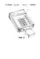
- FIG. 1is a pictorial view of the preferred embodiment of the present invention.
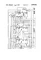
- FIG. 2is a schematic diagram of the preferred embodiment of the present invention.
- FIG. 3is a logical flow diagram of the microcomputer firmware which controls the preferred embodiment.
- FIG. 4is a block diagram of the preferred embodiment of the present invention in its preferred environment.
- FIG. 1is a pictorial view of the exterior of the preferred embodiment of the present invention shown generally at 10.
- the preferred embodimentis contained within a housing 11 having a window 12 for an LCD display element.
- the upper surface of housing 11measures approximately 14 centimeters by 8 centimeters and will thus be seen to meet the above noted object to provide a compact controller.
- Window 12is to provide visible access to a dot matrix LCD display element in which simple messages are provided to the user during operation of the preferred embodiment.
- a slot 13 containing a plug connectoris provided at the front of the preferred embodiment for accepting EEPROM and PROM memory cards and cartridges 14 of a type described hereinbelow. These cards and cartridges contain the microcomputer courseware, and other information, described in greater detail in this specification.
- a standard type DB25 25 pin female connector(not shown) disposed on the rear of controller 10 which is used to interconnect the preferred embodiment with the video disc player being controlled and also to implement connections to digital computing and other serial I/O device described hereinbelow.
- housing 11has a keypad 15 disposed thereon consisting of a conventional 4 ⁇ 3 keypad 16, which mimics a standard telephone keypad and a 5 key array 17 of special control keys used the preferred embodiment.
- keypad 15is selectively operated by the user to provide user response signals in response to messages displayed in display window 12 and to messages produced on the monitor screen by the video courseware in use.
- the significance of the signals from 4 ⁇ 3 keypad 16is controlled by the microcomputer courseware used with the instructional course in operation at any given time.
- the user response signals from subpad 17provide general video playback command signals and signals to the operating system of the preferred embodiment to provide, for example, a menu of options and help messages in LCD window 12, or on the monitor screen.
- the preferred embodimenton startup of any interactive instructional program using particular video courseware and controlled by microcomputer courseware, the preferred embodiment first checks to ascertain if a VDC selection signal has been stored. If none has, the user is first prompted with a menu of the video disc player types which are supported by the preferred embodiment, and asked to select one. The user depresses one of the keys on subpad 17 when the name of the particular video disc playback apparatus used in the system is displayed, and the VDC selection signal is then stored by the preferred embodiment. So long as operation of the preferred embodiment continues, it will always check the VDC selection signal and use this stored value to select appropriate output signals from the VDC characterization values to thus provide the correct electrical control signals to the video disc player in use.
- FIG. 2which consists of FIGS. 2A through 2D, is a schematic diagram of the preferred embodiment.
- the preferred embodimentmeets object of implementing a simple and inexpensive controller. It uses a relatively small number of widely available parts and thus can be built much less expensively than general purpose programmable digital computers which have been used to implement video disc playback controllers for interactive systems heretofore.
- microcomputer 30is built around microcomputer 30.
- microcomputer 30is embodied by a type Z8681 one chip microcomputer of the Z8 family currently manufactured by Zilog, Inc. of Cupertino, California.
- the Z8681is a member of the Z8 having no internal mask programmed read only memory.
- four 8 bit portsconventionally numbered in literature published by the manufacturer as port O-3, are provided on microcomputer 30.
- the Zilog Components Data Bookpublished in 1985 by Zilog, Inc. of Cupertino, California, is hereby incorporated by reference, exactly as if set forth herein.
- the output lines from port Oare shown collectively at 31 in FIG. 2A.
- 8 bit bus 31 primary functionis to provide the eight highest order address bits for the system address bus.
- the 8 bit bus attached to port 1is shown as 32 in FIG. 2A.
- portserves as both the data bus and the output bus for the eight lowest order address bits which are stored in a conventional manner during each addressing function in low order address byte latch 35.
- Bus 32is connected to port 1 of microcomputer 30 and also serves as the bidirectional data bus for microcomputer 30.
- elements attached to 8 bit bus 32are connected to the system data bus and those connected to the 8 bit bus 36, connected to the output side of low order address byte latch 35, are connected to the least significant 8 bits of the system address bus.
- Port 2 of microcomputer 30is connected to an 8 bit input/output bus shown as 37.
- the port 2 pins of the Z8 family of microcomputersare bidirectional I/O ports and are bit programmable. Therefore, lines 37 connected to port 2 of the Z8 are particularly suited for writing control outputs to the video disc player connected to the preferred embodiment. Indeed, this is what the majority of the port 2 lines of bus 37 are used for in the preferred embodiment.
- I/O select outputis provided to two of the enable inputs on I/O selector 41.
- I/O selector 41is a 3 bit to 1-of- 8 which selects one of the system I/O device for reading or writing.
- the decoded output on line 42selects serial input/output reading by enabling the read function on type 8530 dual USART or communications controller 45 (FIG. 2D).
- microcomputer 30is enabled to read or writ serial data from dual USART 45.
- line 46enables keyboard read buffer 47 by placing its outputs in a low impedance state, thus placing the data stored in this device on to date bus 32.
- Output line 48 from decoder 41enables keypad write latch 49.
- Line 50enables yet another latch 51 which writes an 8 bit state to its outputs shown collectively at 52. (FIG. 2D. )
- the output from latch 51enables various devices such as an audible beeper 55, power supply control transistor 56 for the EEPROM card, and provides partitioning of the address space of the EEPROM or PROM memory card through a pair of lines shown as 57.
- Keypad 15is shown on FIG. 2B and is a cross-point matrix keypad wherein depression of a key activates a connection between one of row lines 58 and column lines 59.
- the preferred embodimentdetects user response inputs from keypad 15 by the conventional scheme of writing a particular logical value to one of column lines 59 and then reading the output from keypad read buffer 47 to determine if one of the row lines is in the same state. Since microcomputer 30 knowns the particular line enabled by keypad write buffer 49 at any given time, the particular one of lines 58 which carries the same state allows the microcomputer 30 to uniquely determine the keypad pressed. Also, in a conventional manner, states in which two keys are depressed at the same time are ignored. Appropriate selection of timing for the keyboard scanning routine, software debouncing is accomplished in a conventional manner.
- a standard resistor array shown at 60provides pull-up to keyboard row lines 58.
- a plug connector 65is shown on FIG. 2D for the LCD display which appears under window 12 (FIG.1).
- a tap to data bus 32is brought in to the LCD plug at 66.
- Read/write strobe line 38is connected to one pin, the lowest order address bit (AO) is brought in on line 67 from the latched low order address byte bus 36 (FIG. 2C) and a decoded select input is provided on line 68 from I/O decoder 41 (FIG. 2A).
- the LCD display used in the preferred embodimentis a dot matrix display of a conventional type which the display circuitry contains appropriate addressing and memory circuits. Both data for display and address information is bought in from data bus 32 at 66 on plug connector 65.
- the system read/write strobe on line 38causes writing of date to be displayed into the memory elements of the display.
- the lowest order address bit on line 67controls whether the data present at 66 is data to be displayed, or address data designating the position within the LCD display at which the data is to shown.
- Circuit 45 shown of FIG. 2Dis a type Z8530 serial communications controller. As noted hereinabove, this device essentially serves the function as a two channel, or dual, universal synchronous/asynchronous receiver transmitter (USART). The operation of the type Z8530 dual USART is described in detail in literature provided by the manufacturer of this device and similar devices. For example, its operation is described in pages 839 through 860 of Zilog Components Date Book published in 1985 by Zilog Corporation, which is hereby incorporated by reference as is fully set forth herein. For purposes of the current specification, it need only be noted that communications controller 45 communicates with microcmputer 30 through the following conventional connections.
- A/B and D/C inputsshown collectively on line pair 69 are connected to the two lowest order address bits of address bus 36. These inputs control selection of the A or B communications channel and as detemination of whether the data present on data bus 32 (when microcomputer 30 is communicating which controller 45) is data for communication channel or a command to the controller 45. Similarly, an interrupt request output is brought out on line 70 and provided to pin 2 of port 3 of microcomputer 30 which responds to interrupt request. In a conventional manner, communications controller 45 requests an interrupt to microcmputer 30 when it has date stored in appropriate registers which need to be passed to the microcomputer. An interrupt acknowledge signal is provided on line 71 which is one of the collective outputs shown as 52 from latch 51. Thus the interrupt acknowledge is written by microcomputer 30 to a paritcular address location when the signal is required.
- Communication controller 45controls serial communication into and out of the preferred embodiment. In particular, it controls RS-232 serial data links provided to various video disc players which require same. Communications controller 45 also provides for serial communication with an external computing device for applications and operations, described hereinbelow, which require same.
- EIA Standard RS-232 for serial communicationsspecify a relatively large number of signal conductors. It is also known to those skilled in the art that very few of the signals are actually provided or deteced in a very large majority of the real world implementations of an RS-232 communications port. Indeed, implementation of the full RS-232 specification in this day and time is a dangerous activity since there are very few devices which implement the entire specification. Therefore, equipment expecting responses from and providing outputs to all of the RS-232 defined signal lines is unlikely to work properly when connected to most commercially available devices. In acknowledgement of this, the two serial channels of communications controller 45 are alternately configured to bring out two signal lines and four signal lines, excluding the signal grounds.
- the A channelonly brings outs transmit data line 75 and receive data line 76.
- the B channelbrings out transmit data line 77 and receive data line 78. It also provides clear to send signal (CTS) on line 79 and a request to send signal on line 80.
- CTSclear to send signal
- RS-232 signal linesare provided to line driver circuits 81 and 82 which perform conventional level shifting functions between the TTL logic levels on the inputs and outputs of communication controlled 45 and RS-232 levels which appear at RS-232 ports 85 and 86.
- Two lines designated as 87 and 88are provided to line driver circuit 81. These lines are connected to lines 0 and 7respectively, of port 3 of microcomputer 30 (FIG. 2A). Pin 0 of port 3 is an input line and pin 7 of port 3 is an output line. As will be known to those skilled in the art, these pins of port 3 of a Z8 type microcomputer are commonly used, as they are in the preferred embodiment, to directly implement the signals for a serial communications link. On the RS-232 side (the right hand side of the drawing figure) of FIG. 2D, these lines come through as serial port 84.
- serial port 84is a two line (that is, transmit data and receive data) RS-232 level serial port which is controlled directly from port 3 of microcomputer 30 (FIG. 2A). Therefore, there are three RS-232 serial ports 84 through 86 provided in the preferred embodiment. Two of these ports, 85 and 86, are driven through serial communications controller 45, and the other port 84 is controlled directly from port 3 of the microcomputer.
- the 8 line comprising the RS-232 ports together with 11 TTL level lines shown collectively as 89,are provided to the electrical conductors of a DB-25 connector represented at 90.
- an 8 line subset of lines 89is electrially identical to bus 37 from port 2 of microcomputer 30 (FIG. 2A).
- 8 of the conductor provided to DB25 connector 90are the bit programmable outputs from port 2 of the microcomputer.
- Eight bit bus 37is brought out to connector 90 for the control of the second type of quasi-standard level 3 control port for a video disc player, as described hereinabove. It should be recalled that this is the type of quasi-standard port which requires 8 bit latched parallel I/O to the control port on the disc player.
- control to the video disc playeris provided directly through 8 bit bus 37.
- instructions to the disc player written out on bus 37 and the state of bus 37is read back to microcomputer 30 for detecting acknowledgement and state signls from the disc player.
- the third type of quasi-standard level 3 control described hereinaboveis implemented through one line of bus 37 and line 91.
- the third type of level 3 controlis a TTL level serial data output to the video disc player combined with a dedicated acknowledge line input from the disc player.
- One of the bit programmable lines on bus 37is used to implement the serial data output to video disc players of this type through DB25 connector 90.
- Line 91is brought from connector 90 to pin 1 of port 3 of microcomputer 30 (FIG. 2A). This seves as a second interrupt request line which is used to generate interrupts in response to state transitions on the acknowledge output of this type of video disc player.
- a pair 92 of two currently unused TTL input/output linesare provided to keypad read buffer 47. These are connected through buffer 47 on to two lines of data bus 32. These lines are available to detect any additional TTL level outputs which may be provided at the level 3 control port of a video disc player designed in the future or other real world signals related to the system.
- DB-25 connector 90provides a connection means which includes a plurality of electrical signal pads for connecting the controller of the preferred embodiment to a control port on at least one of the video disc players supported by the preferred embodiment.
- the signal lines 18 coming into DB-25 connector 90do not resemble any standard implementation of RS-232, or other common uses of DB- ⁇ connectors. Since it is one object of the present invention to keep the dedicated controller small, a non-standard set of electrical signals was provided to a DB-25 connector to provide both two channels of serial input/output, and all the necessary input and output signal lines for connection to the control ports of various video disc players. Therefore, the preferred embodiment of the present invention is designed to be used with non-standard cabling connector which interconnect the various lines of DB-25 connector 90 to the appropriate characteristic control port connector used by various video disc manufacturers and to standard implementations of RS-232 on external devces. The techniques for selecting and making such non-standard cables 18 are well knwon to those skilled in the art.
- connector 90is used to interconnect the preferred embodiment with up to 5 ports.
- Three of the portsare RS-232 level serial ports, one port is a TTL serial port with the knowledge line 91, and the last port is the 8 bit TTL level parallel port implemented through bus 37, plus the pair 92 of TTL input/output lines.
- TTL level serial port described hereinis currently designed for unidirectional serial transmission since this is all that is currently required for TTL level serial communication among commercially available video disc players.
- bidirectional communicationscould br implemented by the use of appropriate interrupt service routines for servicing interrupts generated by transitions on line 91 to directly decode incoming serial data.
- FIGS. 2C and 2DThe memory elements used in the preferred embodiment are shown on FIGS. 2C and 2D.
- the preferred embodimentemploys a pair of 32K static RAM chips 95 and 96. As noted hereinabove, these are selectively enable by memory decoder 39.
- RAM 95is referred to as battery RAM since its contents are protected by a conventional battery backup and clock circuit (not shown). In the preferred embodiment, the battery backup and clock circuit is mounted in the socket.
- Random access memory 96is referred to as the course RAM since it is normally used to contain the microcmputer courseware which controls the algorithmic interaction between the display of frames from the video courseware, the user response signals provided from keyboard 15 and other transient information.
- One predetermined address of RAM 95stores the VDC selection signal described hereinabove, which indicates the particular type of video disc player to which the preferred embodiment is connected.
- RAM 95contains operating system control instructions for microcmputer 30 for executing all of its repetitive standard functions which are independent of the instructions contained in the microcomputer courseware.
- RAM 96is referred to as the course RAM since it is normally used to store program instruction signals to microcomputer 30 for implementing the particular course in question. It will thus be appreciated that at least one address of RAM 95 comprises a first storage means for storing the VDC selection signal. Additional address locations of RAM 95 comprise a second storage means for storing a plurality of sets of VDC characterization signals, each set of which corresponds to one of a plurality of video disc playback machines. Lastly, RAM 95 comprises a third storage means for providing control signals to microcomputer 30.
- the memory shown on FIG. 2Cis is preferbly implemented by the plug in surface mounted PROM and EEPROM memory described hereinabove and represented at 98 on the drawing figures.
- low order 8 bits of the address inputs to EEPROM 98are connected to the low order latched address bus 36.
- the next six most significant address bitsare connected to the six lowest order bits of the high order address bus 31 (FIG. 2A).
- the two most significant address inputs to EEPROM 98are connected to line to line pair 57 and thus the states on these, lines, latched into latch 51, partition memory 98 into four segments.
- memory 98is shown as a wired device on FIG. 2C, it is implemented by a plug connected device in the preferred embodiment and thus the representation on the drawing figure is solely as that of an electrical schematic.
- memory 98there are several uses of memory 98 which lead to some of the novel improved features of the present invention. For example, certain addresses of memory 98 are dedicated to storing the following signals. At least one address stores a card type identification signal for the EEPROM memory. Additionally, certain addresses of memory 98 are set aside for used identification codes.
- the card types defined by the present inventionare a course card which contains microcomputer courseware, a user card, an administrator card, and a system card. It the card is a course card, and appropriate signals are provided to keypad 15, microcomputer 30 will transfer the program control signals of the microcomputer courseware into course RAM 96. Alternately, microcomputer 30 may direclty read the program instructions from a course card over data bus 32.
- the user identification cardidentifies the particular user and enables that user to proceed with operation of the interactive system. If it is a testing and/or academic construction setting, the system also stores in battery RAM 95 an indication of the user identification from EEPROM 98 and a data and time entry indicating the time of use. Whether or not this particular information is stored is controlled by the courseware in use by the operator of the system.
- an administrative card identification signalis one which allows certain user data stored in battery RAM 95 to be downloaded and written to the EEPROM of memory 98 for offsite processing. From this it will be appreciated that additional addresses of battery RAM 95 constitute a fourth storage means contained within housing 11 (FIG. 1) for storing result data in response to user response signals provided from keyboard 15 as the student or other user interacts with the system. Additionally, for cards containing an administrative identification code, portions of EEPROM 98 comprise a fifth storage means contained within a descrete selectively connectable device which includes read/write memory for selectively storing the result data from batterys RAM 95 when the card is inserted and at least one predetermined user response signal is provided from keypad 15.
- system card identificationis one which allows certain data stored on the EEPROM to be uploaded to the battery RAM to reprogram its functions and confirmation of this event download to the EEPROM.
- One excellent use for interactive video disc systems employing the preferred embodimentis that of academic instruction.
- appropriate video courseware and microcomputer coursewarehas been prepared by an instructor in such an environment.
- a plurality of interactive video systems, each of which employs the preferred embodiment of the present invention as a controllerare provided at a location accessible to a plurality of students at various times during a predetermined academic term.
- the instructorprepares appropriate video and microcomputer courseware.
- Each studentis issued a card which contains a user identification signal stored in the EEPROM and also identifies it as a course card.
- Appropriate copies of the video coursewareare made available at the locations where the interactive video discs are stored. Once the student user gets an opportunity to operate one of the systems, he or she selects a disc containing the appropriate courseware and inserts it into the video disc player (not shown). Microcomputer 30 then loads the course instructions from PROM card 98 into coures RAM 96 and checks the course identification code on the PROM card. The student inserts the course PROM card into the slot 13 (FIG. 1). The student is told to remove the course card and insert his or her EEPROM card into the slot 13 so that the card becomes the embodiment of memory 98 shown in FIG. 2B. Appropriate information, determined by the microcomputer courseware, stores information about the particular student's use of the system in battery RAM 95.
- the studentmay then proceed to go through the instructional routine defined by the coureware. It should also be noted that (solely under the control of the courseware) at the termination of each session, signals may be written out to the EEPROM card 98 indicating the point in the instructional sequence through which the student had proceeded at the time the session was terminated. This allows the student to pick up at the appropriate portion of the course the next time the system is operated. From time to time, the courseware determines that tests should be given to the student under the control of the microcomputer courseware. At a time of the student's selection, the test is taken. The student's responses to the test question, together with an idenitfication of the particular student are storde in battery RAM 95.
- the professorcan proceed to each machine in the environment in question, and insert his or her EEPROM card containing an administrative identification code. Operation of an appropriate key from keypad 15 causes microcomputer 30 to check the administrative identification code, and upon confirmation of same, to download information a student identifications and test scores to the EEPROM 98. This information may then be taken to a compatible offsite data reading device for downloading and translation into text with student name and information allowing the professor to score the various tests.
- microcomputer coursewarecan be downloaded into course RAM 96 through either of serial ports 84 through 86. Futhermore, in an appropriate environment, student scoring information or the like may be downloaded through the serial ports if the courseware requires an appropriate password code to be entered through the serial port prior to transmitting restricted access data to the serial ports in a response to a request that it be provided.
- serial or parallel TTL level data communications devicesmay be connected to the preferred embodiment through port 90.
- the inventors of the present inventionhave designed systems for implementing the card reading functions described hereinabove which connect a conventional RS-232 serial port from a digital computer to the preferred embodiment in order to extract data from administrative EEPROM cards as described hereinabove.
- an available device implementing the preferred embodimentmay simply be used as a card reader and appropriate software is used on a general purpose digital computer connected to one of the serial ports in order to read the data from the software into the computer's memory for appropriate analysis and processing.
- the implementation of 5 ports through a single DB25 connectorallow the preferred emobdiment to achieve its object of remaining small and compact and having great versatility as a data communications device as well as a dedicated controller for various types of laser video disc players.
- the apparatusis extremely flexible and provides, solely under the control of the operating system stored in memory 95 and appropriate courseware in either of memories 96 or 98, as wide variety of options for downloading courseware and storing information on user responses.
- FIG. 3shows a high level flow diagram of the firmware controlling the preferred embodiment. It begins with block 110 at the top of FIG. 3.
- Block 110simply represents a loop in which a test for a keyboard input is implemented at step 111. If a valid keyboard signal is present YES branch 112 is taken. If no valid keyboard input is present, no branch 115 is taken looping back to the test. It will be understood by those skilled in the art that execution of the loop surrounded by dashed line 110 represents implementation of writing to keypad write buffer 49 and reading from keypad read buffer 47, as described hereinabove in connection with FIG. 2B.
- loop 110There is one other significant aspect of loop 110 which should be understood.
- the preferred embodiment of the present inventionis an interrupt driven machine.
- the exception to this statementis the loop represented by 110 in which scans of keyboard 15 are made.
- other routines of the preferred embodimentare handled as interrupt service routines. These will most often occur as an exit to an interrupt service routine from loop 110, although the exact sequence will be determined by the interrupt priority established in firmware.
- serial communications controller 45(FIG. 2D) needs to provide data to microcmoputer 30, it generates an interrupt request on line 70 as described hereinabove.
- microcomputer 30will execute a conventional interrupt service routine (not shown in FIG. 3 ) for accepting a parallel serial byte from a USART.
- a interrupt requestis generated on line 91, the appropriate service routine for analyzing an acknowledge signal from a video disc player is executed.
- FIG. 3represents the flow control for the preferred embodiment at a high level.
- Those skilled in the artwill know the details of implementations of such a routine with a microcomputer, and there are many persons of average skill in the art who can prepare Z8 assembly language instructions for final implementation of the routines described.
- keyboard checking routinesare used in the preferred embodiment and are considered a part of test step 110, For example, the preferred embodiment rejects keypad conditions in which more than one key is depressed.
- software debouncingis performed before microcomputer 30 determines that a valid key press has been detected and sends the flow control to YES branch 112.
- YES branch 112goes to an exit point 116 labeled "A ". This is shown as connected by dashed line 117 to entry point 118 labeled "A ".
- the significance of this connectionis to indicate that the keyboard service routine is conducted in essentially the same fashion as an interrupt service request.
- interrupt serviceswould be represented by a plurality of different exits from loop 110.
- the first step of the keyboard service routineis the "read courseware command record" routine shown at 119.
- Thisis a routine wherein a courseware command record is read from a courseware command record register.
- the preferred embodimentreasds, a pointer stored in a particular register of microcomputer 30. This pointer points to the current courseware command record within the microcomputer courseware storde in course RAM 96 (FIG. 2C).
- the coursewarse command recordswhich embody the microcomputer courseware described hereinabove, are variable length records stored in the course. RAM. Each recod contains a fixed length hearder indicative of the particular ones of keypad 15 (FIGS.
- a testis executed at 120 to determine if the particular key which was operated is enabled for this couresware command record. If it is not no branch 121 is taken and the machine does a subroutine return shown at 122. This taken program flow control back into loop 110 awaiting the next keyboard response.
- step 126labeled "get command record of this key”. As described hereinabove, this step is one which responds to the command record pointer associated with a particular enabled key. The pointer for this command record is loaded into the command pointer register and the machine then goes to step 127 labeled "execute command”. It will be appreciated by those skilled in the art that this step simiply means fetching the instruction from the address in the courseware RAM indicated by the command record read at step 126.
- STEP 127is contained within a block surrounded by dashed line 128. It should be understood by those skilled in the art that block 128 actually represents fetching and execution of the instruction pointed to by the address in the command pointer register. However, it is broken out into steps 127, 129 and 130 to explain the functional response of the machine rather than the actual software implementation of fetching and executing the command to which the register points.
- a testis represented. This test is to determine whether the command to be executed requires video disc control output. It it does not, No branch 131 is taken to execute whatever non-VDC output routine is required by the particular command. This is represented as "do service routine" block 132. When routine 132 is completed, a subroutine return is made at 135.
- routine 132represents all the other possible non-VDC control routines executed by the preferred embodiment.
- service routine 132would represent the routine which writes the VDC selection signal to its dedicated address in memory.
- Oher routines for displaying messages and general overhead of the preferred embodimentwill also be executed for commands which do not require video disc control output.
- Another service routine represented by 132is the rountine of testing for card type and user identification signals describe hereinabove.
- these routinesare executed, particular addresses on the EEPROM card 98 are read to determine the type of card and a code representative of the card holders authorization level for access to information from the preferred embodiment. As described hereinabove, reading of information from or writing information to various locations of memory 98 will then take place in response to subsequent keyboard inputs.
- the command record for this particular keycontains information which generically defines a video disc control command signal, as described hereinabove.
- the video disc command signalmay be one which indicates that the disc player should step to fame 150 and display that frame.
- the video disc control command signal at this pointis independent of the particular player in use at the time.
- Dashed line 137represents the branch to player driver entry point 138 and should thus be understood to represent a subroutine call executed at 130 with entry of the subroutine at 138.
- the player driver routineis represented by the steps surrounded by dashed line 140 in FIG. 3.
- the first step of the player driver routineis to read the VDC selection signal which is labeled "go to VDC driver for this video disc command", shown at 142.
- microcomputer 30makes a logical combination of the stored VDC selection signal and the logical representation of the video disc command to point to a particular service routine in the portion of battery RAM 95 (FIG. 2C) containing the VDC characterization signals.
- the VDC characterization signalsare nothing more than player specific commands to microcomputer 30 to provide particular electrical outputs.
- microcomputer 30are listed in a listed in a table containing a set of sequential instructions for microcomputer 30 to provide certain electrical outputs through connector 90 described hereinabove.
- VDC selection signalrepresenting the type of player being used
- video disc command signalrepresenting the generic command of what the player is to do
- the machinesimply steps to "output control signals" step 145.
- microcomputer 30beings fetching instructions from the VDC characterization table which represent the electrical output signals to be provided to a particular video disc player to cause it be execute the generic video disc command.
- step 146is executed.
- the machinerefers to currently execued courseware command record which was selected at step 126 in response to operation of a particular key. This record contains a pointer to the next courseware command record which is then loaded into the courseware command record register.
- a returnis executed at 147 taking the machine back to loop 110.
- the current courseware command record read at step 119is represents the present state of the machine at the time step 119 is executed.
- the particular keystroke which provided the user response input which took the flow control to step 119represents the input to the machine.
- the next course command record seleced at 146which is actually derived from the record read at 126, then represents the new state of the machine. It should be noted than in embodiments of the present invention in which display of a particular frame can represet more than one state, as described hereihabove, the same analysis holds true. However, there will not necessarily be a one to one correspondences between the frame presently being displayed and the pointers in the courseware records to the next possible courseware records.
- FIG. 4is a block diagram of the preferred embodiment of the present invention in its preferred environment.
- Controller 10comprises an LCD dispaly 12, a keypad 15, a battery RAM 95, a course RAM 96, a Z8681 microprocessor, 30, a Z8530 USART 45, line drivers and receivers 81 and 82, a connector 21 at the end of slot 13, and DB ⁇ connector 90.
- keypad 15has a conventional 4 ⁇ 3 keypad 16 and a 5 key array 17.
- RAM 95may be considered to be partitioned into several segments, each of which performs a specific function, such as: storage of VDC characterization signals; storage of the VDC selection signal; storage of a plurality of sets of VDC characterization signals; provision of control signals to the microcomputer; and storage of result data as a response to user response signals.
- Components 12, 15, 21, 30, 45, 95 and 96may be considered to be connected by composite bus 22 which carries address, data, and control signals.
- composite bus 22which carries address, data, and control signals.
- cpmposite buswhich perform address decoding, latching, and buffering are not shown in the figure but are shown in FIG. 2.
- EEPROM 98shown as being located on card 14, can be read by microcomputer 30 once card 14 is inserted into slot 13 so that EEEPROM 98 is electrically connected to composite bus 22 via connector 21.
- EEPROM 98may be considered as being partitioned into several address spaces which perform one or more of the following fucnction: storage of a card type identification signal for the EEPROM memory; storage of user identification codes; storage of microcomputer courseware; and storage of the result data.
- DB25 connector 90is connected to composite bus 22 by bus 92, to the line drivers/receivers 81 and 82 by conductors 84 through 86, and to microcomputer 30 by bus 37 and conductor 91.
- Connector 90provides a connection means which includes a plurality of electrical signal paths for connecting the controlled 10 to a control port 19 on at least one of the video disc players 20. Transfer of electrical signals between connector 19 and 90 is accomplished by multiconductor cable 18.
Landscapes
- Engineering & Computer Science (AREA)
- Multimedia (AREA)
- Business, Economics & Management (AREA)
- Physics & Mathematics (AREA)
- Educational Administration (AREA)
- Educational Technology (AREA)
- General Physics & Mathematics (AREA)
- Theoretical Computer Science (AREA)
- Signal Processing For Digital Recording And Reproducing (AREA)
Abstract
Description
Claims (5)
Priority Applications (1)
| Application Number | Priority Date | Filing Date | Title |
|---|---|---|---|
| US07/082,770US4855842A (en) | 1987-08-06 | 1987-08-06 | Dedicated programmable controller for interactive video disc system |
Applications Claiming Priority (1)
| Application Number | Priority Date | Filing Date | Title |
|---|---|---|---|
| US07/082,770US4855842A (en) | 1987-08-06 | 1987-08-06 | Dedicated programmable controller for interactive video disc system |
Publications (1)
| Publication Number | Publication Date |
|---|---|
| US4855842Atrue US4855842A (en) | 1989-08-08 |
Family
ID=22173360
Family Applications (1)
| Application Number | Title | Priority Date | Filing Date |
|---|---|---|---|
| US07/082,770Expired - Fee RelatedUS4855842A (en) | 1987-08-06 | 1987-08-06 | Dedicated programmable controller for interactive video disc system |
Country Status (1)
| Country | Link |
|---|---|
| US (1) | US4855842A (en) |
Cited By (51)
| Publication number | Priority date | Publication date | Assignee | Title |
|---|---|---|---|---|
| US5051973A (en)* | 1987-12-19 | 1991-09-24 | Pioneer Electronic Corporation | Method for playing back music pieces recorded on recording media |
| US5056071A (en)* | 1987-09-30 | 1991-10-08 | Deutsche Thomson-Brandt Gmbh | Cd apparatus with dynamic function generation |
| FR2665288A1 (en)* | 1990-07-27 | 1992-01-31 | Pioneer Electronic Corp | System for explaining exposed objects |
| US5093731A (en)* | 1987-05-19 | 1992-03-03 | Fuji Photo Film Co., Ltd. | Image data recording apparatus for storing image data with a recording-finished code and a recording sequence code |
| US5161034A (en)* | 1989-07-18 | 1992-11-03 | Wnm Ventures Inc. | Branching table for interactive video display |
| US5206929A (en)* | 1990-01-19 | 1993-04-27 | Sony Corporation Of America | Offline editing system |
| WO1993000768A3 (en)* | 1991-06-25 | 1993-04-29 | David Rayne Clark | Video and/or audio data reproduction system and controller therefor |
| US5241659A (en)* | 1990-09-14 | 1993-08-31 | Eastman Kodak Company | Auxiliary removable memory for storing image parameter data |
| US5420838A (en)* | 1989-06-30 | 1995-05-30 | Sharp Kabushiki Kaisha | Disk recording and reproducing device |
| US5454722A (en)* | 1993-11-12 | 1995-10-03 | Project Orbis International, Inc. | Interactive multimedia eye surgery training apparatus and method |
| US5497362A (en)* | 1988-07-04 | 1996-03-05 | Canon Kabushiki Kaisha | Drive interface for performing write/read of information |
| EP0713333A1 (en)* | 1994-11-19 | 1996-05-22 | Società Italiana per lo Sviluppo dell'Elettronica S.I.SV.EL. S.p.A. | Television receiver with apparatus for the quick exchange of data concerning instructions and/or functions |
| US5617535A (en)* | 1992-03-03 | 1997-04-01 | Hitachi, Ltd. | Recording and playbackk apparatus |
| US5663901A (en)* | 1991-04-11 | 1997-09-02 | Sandisk Corporation | Computer memory cards using flash EEPROM integrated circuit chips and memory-controller systems |
| US5689676A (en)* | 1988-04-28 | 1997-11-18 | Sony Corporation | Sequential EEPROM writing apparatus which sequentially and repetitively replaces a head position pointer with a last position pointer |
| US5724102A (en)* | 1995-07-24 | 1998-03-03 | Coach Master International Corporation | Systems in which information can be retrieved from an encoded, laser readable disc |
| US5748253A (en)* | 1995-10-12 | 1998-05-05 | Asc Audio Video Corporation | Direct keyboard access to video editing source material |
| US5801784A (en)* | 1995-12-08 | 1998-09-01 | Coach Master International | Data storage devices |
| US5857029A (en)* | 1995-06-05 | 1999-01-05 | United Parcel Service Of America, Inc. | Method and apparatus for non-contact signature imaging |
| US5857917A (en)* | 1994-06-16 | 1999-01-12 | Francis; Mitchell J. | 3-D simulator ride |
| US5887243A (en) | 1981-11-03 | 1999-03-23 | Personalized Media Communications, L.L.C. | Signal processing apparatus and methods |
| US5898462A (en)* | 1995-12-08 | 1999-04-27 | Coach Master International Corporation | Methods of producing data storage devices for appliances which can be used to coach users in the performance of user-selected tasks |
| US5969715A (en)* | 1995-04-26 | 1999-10-19 | Wink Communications, Inc. | Compact graphical interactive information system |
| US5974389A (en)* | 1996-03-01 | 1999-10-26 | Clark; Melanie Ann | Medical record management system and process with improved workflow features |
| EP0886277A3 (en)* | 1997-06-20 | 2000-07-12 | Pioneer Electronic Corporation | Information reproducing system |
| US6113500A (en)* | 1999-03-18 | 2000-09-05 | Cinema Ride, Inc. | 3-D simulator ride |
| US6282611B1 (en)* | 1990-07-11 | 2001-08-28 | Hitachi, Ltd. | Digital information system, digital audio signal processor and signal converter |
| US20020191955A1 (en)* | 1994-11-28 | 2002-12-19 | Shigeaki Koike | Data recording and reproducing apparatus |
| US6631101B1 (en) | 1999-03-16 | 2003-10-07 | Gateway, Inc. | System, method, and software for recovering from interruption of DVD playback |
| US20040167769A1 (en)* | 2003-02-26 | 2004-08-26 | Xerox Corporation | User-tailorable romanized chinese text input systems and methods |
| US20050001035A1 (en)* | 2003-05-12 | 2005-01-06 | Thomas Hawley | Picture taking optical reader |
| US20050014563A1 (en)* | 2003-03-12 | 2005-01-20 | Darin Barri | Interactive DVD gaming system |
| US20050094524A1 (en)* | 2003-10-29 | 2005-05-05 | Ping-Sheng Chen | Method for handling interrupt request in optical storage drive |
| US6942151B2 (en) | 2001-05-15 | 2005-09-13 | Welch Allyn Data Collection, Inc. | Optical reader having decoding and image capturing functionality |
| US20060111184A1 (en)* | 2004-11-03 | 2006-05-25 | Peter Maclver | Gaming system |
| US20060111185A1 (en)* | 2004-11-03 | 2006-05-25 | Peter Maclver | Gaming system |
| US20060111166A1 (en)* | 2004-11-03 | 2006-05-25 | Peter Maclver | Gaming system |
| US20060111183A1 (en)* | 2004-11-03 | 2006-05-25 | Peter Maclver | Remote control |
| US20060121965A1 (en)* | 2004-11-03 | 2006-06-08 | Peter Maclver | Gaming system |
| US7111787B2 (en) | 2001-05-15 | 2006-09-26 | Hand Held Products, Inc. | Multimode image capturing and decoding optical reader |
| US7222789B2 (en) | 1997-10-17 | 2007-05-29 | Hand Held Products, Inc. | Bar code reading device having image processing mode |
| US7287697B2 (en) | 2001-07-13 | 2007-10-30 | Hand Held Products, Inc. | Optical reader having a color imager |
| US7293712B2 (en) | 2004-10-05 | 2007-11-13 | Hand Held Products, Inc. | System and method to automatically discriminate between a signature and a dataform |
| US20080166108A1 (en)* | 2007-01-09 | 2008-07-10 | Samsung Electronics Co., Ltd | Optical record/playback apparatus and control method thereof |
| US7443303B2 (en) | 2005-01-10 | 2008-10-28 | Hill-Rom Services, Inc. | System and method for managing workflow |
| US7769344B1 (en) | 1981-11-03 | 2010-08-03 | Personalized Media Communications, Llc | Signal processing apparatus and methods |
| US8382567B2 (en) | 2004-11-03 | 2013-02-26 | Mattel, Inc. | Interactive DVD gaming systems |
| US20130124759A1 (en)* | 2011-04-21 | 2013-05-16 | Touchstream Technologies, Inc. | Play control of content on a display device |
| US8657200B2 (en) | 2011-06-20 | 2014-02-25 | Metrologic Instruments, Inc. | Indicia reading terminal with color frame processing |
| USRE47642E1 (en) | 1981-11-03 | 2019-10-08 | Personalized Media Communications LLC | Signal processing apparatus and methods |
| US11086934B2 (en) | 2011-04-21 | 2021-08-10 | Touchstream Technologies, Inc. | Play control of content on a display device |
Citations (11)
| Publication number | Priority date | Publication date | Assignee | Title |
|---|---|---|---|---|
| US4142232A (en)* | 1973-07-02 | 1979-02-27 | Harvey Norman L | Student's computer |
| US4449198A (en)* | 1979-11-21 | 1984-05-15 | U.S. Philips Corporation | Device for interactive video playback |
| US4464733A (en)* | 1981-07-23 | 1984-08-07 | U.S. Philips Corporation | Office system comprising terminals, a data processor and auxiliary apparatus and a switching device for mass data transport between the auxiliary apparatus |
| US4527262A (en)* | 1982-07-28 | 1985-07-02 | Manto Incorporated | Information storer and retriever |
| US4609358A (en)* | 1981-06-26 | 1986-09-02 | Sangster Bruce F | Video training system for simulataneously training a plurality of students |
| US4626847A (en)* | 1983-12-27 | 1986-12-02 | Zenith Electronics Corporation | Remote control transmitter system |
| US4630231A (en)* | 1983-01-31 | 1986-12-16 | Victor Company Of Japan, Ltd. | Control program signal demodulating device |
| US4641295A (en)* | 1983-09-01 | 1987-02-03 | Sony Corporation | Disc playback apparatus |
| US4685001A (en)* | 1984-08-24 | 1987-08-04 | Eastman Kodak Company | Method for retrieving unedited video still pictures |
| US4703450A (en)* | 1982-08-20 | 1987-10-27 | Pioneer Electronic Corporation | Interface device |
| US4717971A (en)* | 1984-08-24 | 1988-01-05 | Eastman Kodak Company | Partitioned editing method for a collection of video still pictures |
- 1987
- 1987-08-06USUS07/082,770patent/US4855842A/ennot_activeExpired - Fee Related
Patent Citations (11)
| Publication number | Priority date | Publication date | Assignee | Title |
|---|---|---|---|---|
| US4142232A (en)* | 1973-07-02 | 1979-02-27 | Harvey Norman L | Student's computer |
| US4449198A (en)* | 1979-11-21 | 1984-05-15 | U.S. Philips Corporation | Device for interactive video playback |
| US4609358A (en)* | 1981-06-26 | 1986-09-02 | Sangster Bruce F | Video training system for simulataneously training a plurality of students |
| US4464733A (en)* | 1981-07-23 | 1984-08-07 | U.S. Philips Corporation | Office system comprising terminals, a data processor and auxiliary apparatus and a switching device for mass data transport between the auxiliary apparatus |
| US4527262A (en)* | 1982-07-28 | 1985-07-02 | Manto Incorporated | Information storer and retriever |
| US4703450A (en)* | 1982-08-20 | 1987-10-27 | Pioneer Electronic Corporation | Interface device |
| US4630231A (en)* | 1983-01-31 | 1986-12-16 | Victor Company Of Japan, Ltd. | Control program signal demodulating device |
| US4641295A (en)* | 1983-09-01 | 1987-02-03 | Sony Corporation | Disc playback apparatus |
| US4626847A (en)* | 1983-12-27 | 1986-12-02 | Zenith Electronics Corporation | Remote control transmitter system |
| US4685001A (en)* | 1984-08-24 | 1987-08-04 | Eastman Kodak Company | Method for retrieving unedited video still pictures |
| US4717971A (en)* | 1984-08-24 | 1988-01-05 | Eastman Kodak Company | Partitioned editing method for a collection of video still pictures |
Non-Patent Citations (2)
| Title |
|---|
| Zilog Data Book, 1985. Front Cover, Inside Cover Sheet, pp. 63 84 (Z8681) and 839 860 (Z8530).* |
| Zilog Data Book, 1985. Front Cover, Inside Cover Sheet, pp. 63-84 (Z8681) and 839-860 (Z8530). |
Cited By (199)
| Publication number | Priority date | Publication date | Assignee | Title |
|---|---|---|---|---|
| US9043859B1 (en) | 1981-11-02 | 2015-05-26 | Personalized Media Communications, Llc | Signal processing apparatus and methods |
| US8607296B1 (en) | 1981-11-03 | 2013-12-10 | Personalized Media Communications LLC | Signal processing apparatus and methods |
| US7814526B1 (en) | 1981-11-03 | 2010-10-12 | Personalized Media Communications, Llc | Signal processing apparatus and methods |
| US7908638B1 (en) | 1981-11-03 | 2011-03-15 | Personalized Media Communications LLC | Signal processing apparatus and methods |
| US7889865B1 (en) | 1981-11-03 | 2011-02-15 | Personalized Media Communications, L.L.C. | Signal processing apparatus and methods |
| US7870581B1 (en) | 1981-11-03 | 2011-01-11 | Personalized Media Communications, Llc | Signal processing apparatus and methods |
| US7849480B1 (en) | 1981-11-03 | 2010-12-07 | Personalized Media Communications LLC | Signal processing apparatus and methods |
| US7864248B1 (en) | 1981-11-03 | 2011-01-04 | Personalized Media Communications, Llc | Signal processing apparatus and methods |
| US7864956B1 (en) | 1981-11-03 | 2011-01-04 | Personalized Media Communications, Llc | Signal processing apparatus and methods |
| US7865920B1 (en) | 1981-11-03 | 2011-01-04 | Personalized Media Communications LLC | Signal processing apparatus and methods |
| USRE48682E1 (en) | 1981-11-03 | 2021-08-10 | Personalized Media Communications LLC | Providing subscriber specific content in a network |
| US7860249B1 (en) | 1981-11-03 | 2010-12-28 | Personalized Media Communications LLC | Signal processing apparatus and methods |
| US7861263B1 (en) | 1981-11-03 | 2010-12-28 | Personalized Media Communications, Llc | Signal processing apparatus and methods |
| USRE48633E1 (en) | 1981-11-03 | 2021-07-06 | Personalized Media Communications LLC | Reprogramming of a programmable device of a specific version |
| USRE48565E1 (en) | 1981-11-03 | 2021-05-18 | Personalized Media Communications LLC | Providing a subscriber specific solution in a computer network |
| USRE48484E1 (en) | 1981-11-03 | 2021-03-23 | Personalized Media Communications, Llc | Signal processing apparatus and methods |
| US7861278B1 (en) | 1981-11-03 | 2010-12-28 | Personalized Media Communications, Llc | Signal processing apparatus and methods |
| US10715835B1 (en) | 1981-11-03 | 2020-07-14 | John Christopher Harvey | Signal processing apparatus and methods |
| USRE47968E1 (en) | 1981-11-03 | 2020-04-28 | Personalized Media Communications LLC | Signal processing apparatus and methods |
| US10616638B1 (en) | 1981-11-03 | 2020-04-07 | Personalized Media Communications LLC | Signal processing apparatus and methods |
| US10609425B1 (en) | 1981-11-03 | 2020-03-31 | Personalized Media Communications, L.L.C. | Signal processing apparatus and methods |
| USRE47867E1 (en) | 1981-11-03 | 2020-02-18 | Personalized Media Communications LLC | Signal processing apparatus and methods |
| US10523350B1 (en) | 1981-11-03 | 2019-12-31 | Personalized Media Communications LLC | Signal processing apparatus and methods |
| US5887243A (en) | 1981-11-03 | 1999-03-23 | Personalized Media Communications, L.L.C. | Signal processing apparatus and methods |
| USRE47642E1 (en) | 1981-11-03 | 2019-10-08 | Personalized Media Communications LLC | Signal processing apparatus and methods |
| US10334292B1 (en) | 1981-11-03 | 2019-06-25 | Personalized Media Communications LLC | Signal processing apparatus and methods |
| US9674560B1 (en) | 1981-11-03 | 2017-06-06 | Personalized Media Communications LLC | Signal processing apparatus and methods |
| US9294205B1 (en) | 1981-11-03 | 2016-03-22 | Personalized Media Communications LLC | Signal processing apparatus and methods |
| US9210370B1 (en) | 1981-11-03 | 2015-12-08 | Personalized Media Communications LLC | Signal processing apparatus and methods |
| US7860131B1 (en) | 1981-11-03 | 2010-12-28 | Personalized Media Communications, Llc | Signal processing apparatus and methods |
| US9038124B1 (en) | 1981-11-03 | 2015-05-19 | Personalized Media Communications, Llc | Signal processing apparatus and methods |
| US7856649B1 (en) | 1981-11-03 | 2010-12-21 | Personalized Media Communications, Llc | Signal processing apparatus and methods |
| US8973034B1 (en) | 1981-11-03 | 2015-03-03 | Personalized Media Communications LLC | Signal processing apparatus and methods |
| US8914825B1 (en) | 1981-11-03 | 2014-12-16 | Personalized Media Communications LLC | Signal processing apparatus and methods |
| US7844995B1 (en) | 1981-11-03 | 2010-11-30 | Personalized Media Communications, Llc | Signal processing apparatus and methods |
| US8893177B1 (en) | 1981-11-03 | 2014-11-18 | {Personalized Media Communications, LLC | Signal processing apparatus and methods |
| US8869228B1 (en) | 1981-11-03 | 2014-10-21 | Personalized Media Communications, Llc | Signal processing apparatus and methods |
| US8869229B1 (en) | 1981-11-03 | 2014-10-21 | Personalized Media Communications, Llc | Signal processing apparatus and methods |
| US8839293B1 (en) | 1981-11-03 | 2014-09-16 | Personalized Media Communications, Llc | Signal processing apparatus and methods |
| US8804727B1 (en) | 1981-11-03 | 2014-08-12 | Personalized Media Communications, Llc | Signal processing apparatus and methods |
| US8752088B1 (en) | 1981-11-03 | 2014-06-10 | Personalized Media Communications LLC | Signal processing apparatus and methods |
| US8739241B1 (en) | 1981-11-03 | 2014-05-27 | Personalized Media Communications LLC | Signal processing apparatus and methods |
| US8711885B1 (en) | 1981-11-03 | 2014-04-29 | Personalized Media Communications LLC | Signal processing apparatus and methods |
| US8713624B1 (en) | 1981-11-03 | 2014-04-29 | Personalized Media Communications LLC | Signal processing apparatus and methods |
| US8683539B1 (en) | 1981-11-03 | 2014-03-25 | Personalized Media Communications, Llc | Signal processing apparatus and methods |
| US8675775B1 (en) | 1981-11-03 | 2014-03-18 | Personalized Media Communications, Llc | Signal processing apparatus and methods |
| US8646001B1 (en) | 1981-11-03 | 2014-02-04 | Personalized Media Communications, Llc | Signal processing apparatus and methods |
| US8640184B1 (en) | 1981-11-03 | 2014-01-28 | Personalized Media Communications, Llc | Signal processing apparatus and methods |
| US8635644B1 (en) | 1981-11-03 | 2014-01-21 | Personalized Media Communications LLC | Signal processing apparatus and methods |
| US8621547B1 (en) | 1981-11-03 | 2013-12-31 | Personalized Media Communications, Llc | Signal processing apparatus and methods |
| US8613034B1 (en) | 1981-11-03 | 2013-12-17 | Personalized Media Communications, Llc | Signal processing apparatus and methods |
| US7856650B1 (en) | 1981-11-03 | 2010-12-21 | Personalized Media Communications, Llc | Signal processing apparatus and methods |
| US7849479B1 (en) | 1981-11-03 | 2010-12-07 | Personalized Media Communications, Llc | Signal processing apparatus and methods |
| US8601528B1 (en) | 1981-11-03 | 2013-12-03 | Personalized Media Communications, L.L.C. | Signal processing apparatus and methods |
| US8587720B1 (en) | 1981-11-03 | 2013-11-19 | Personalized Media Communications LLC | Signal processing apparatus and methods |
| US8584162B1 (en) | 1981-11-03 | 2013-11-12 | Personalized Media Communications LLC | Signal processing apparatus and methods |
| US8572671B1 (en) | 1981-11-03 | 2013-10-29 | Personalized Media Communications LLC | Signal processing apparatus and methods |
| US8566868B1 (en) | 1981-11-03 | 2013-10-22 | Personalized Media Communications, L.L.C. | Signal processing apparatus and methods |
| US8558950B1 (en) | 1981-11-03 | 2013-10-15 | Personalized Media Communications LLC | Signal processing apparatus and methods |
| US8559635B1 (en) | 1981-11-03 | 2013-10-15 | Personalized Media Communications, L.L.C. | Signal processing apparatus and methods |
| US8555310B1 (en) | 1981-11-03 | 2013-10-08 | Personalized Media Communications, Llc | Signal processing apparatus and methods |
| US8395707B1 (en) | 1981-11-03 | 2013-03-12 | Personalized Media Communications LLC | Signal processing apparatus and methods |
| US8191091B1 (en) | 1981-11-03 | 2012-05-29 | Personalized Media Communications, Llc | Signal processing apparatus and methods |
| US8112782B1 (en) | 1981-11-03 | 2012-02-07 | Personalized Media Communications, Llc | Signal processing apparatus and methods |
| US8060903B1 (en) | 1981-11-03 | 2011-11-15 | Personalized Media PMC Communications, L.L.C. | Signal processing apparatus and methods |
| US8046791B1 (en) | 1981-11-03 | 2011-10-25 | Personalized Media Communications, Llc | Signal processing apparatus and methods |
| US7992169B1 (en) | 1981-11-03 | 2011-08-02 | Personalized Media Communications LLC | Signal processing apparatus and methods |
| US7734251B1 (en) | 1981-11-03 | 2010-06-08 | Personalized Media Communications, Llc | Signal processing apparatus and methods |
| US7747217B1 (en) | 1981-11-03 | 2010-06-29 | Personalized Media Communications, Llc | Signal processing apparatus and methods |
| US7752649B1 (en) | 1981-11-03 | 2010-07-06 | Personalized Media Communications, Llc | Signal processing apparatus and methods |
| US7752650B1 (en) | 1981-11-03 | 2010-07-06 | Personalized Media Communications, Llc | Signal processing apparatus and methods |
| US7761890B1 (en) | 1981-11-03 | 2010-07-20 | Personalized Media Communications, Llc | Signal processing apparatus and methods |
| US7764685B1 (en) | 1981-11-03 | 2010-07-27 | Personalized Media Communications, L.L.C. | Signal processing apparatus and methods |
| US7769170B1 (en) | 1981-11-03 | 2010-08-03 | Personalized Media Communications, Llc | Signal processing apparatus and methods |
| US7769344B1 (en) | 1981-11-03 | 2010-08-03 | Personalized Media Communications, Llc | Signal processing apparatus and methods |
| US7774809B1 (en) | 1981-11-03 | 2010-08-10 | Personalized Media Communications, Llc | Signal processing apparatus and method |
| US7783252B1 (en) | 1981-11-03 | 2010-08-24 | Personalized Media Communications, Llc | Signal processing apparatus and methods |
| US7784082B1 (en) | 1981-11-03 | 2010-08-24 | Personalized Media Communications, Llc | Signal processing apparatus and methods |
| US7793332B1 (en) | 1981-11-03 | 2010-09-07 | Personalized Media Communications, Llc | Signal processing apparatus and methods |
| US7849493B1 (en) | 1981-11-03 | 2010-12-07 | Personalized Media Communications, Llc | Signal processing apparatus and methods |
| US7797717B1 (en) | 1981-11-03 | 2010-09-14 | Personalized Media Communications, Llc | Signal processing apparatus and methods |
| US7801304B1 (en) | 1981-11-03 | 2010-09-21 | Personalized Media Communications, Llc | Signal processing apparatus and methods |
| US7805748B1 (en) | 1981-11-03 | 2010-09-28 | Personalized Media Communications, Llc | Signal processing apparatus and methods |
| US7805738B1 (en) | 1981-11-03 | 2010-09-28 | Personalized Media Communications, Llc | Signal processing apparatus and methods |
| US7805749B1 (en) | 1981-11-03 | 2010-09-28 | Personalized Media Communications, Llc | Signal processing apparatus and methods |
| US7810115B1 (en) | 1981-11-03 | 2010-10-05 | Personalized Media Communications, Llc | Signal processing apparatus and methods |
| US7926084B1 (en) | 1981-11-03 | 2011-04-12 | Personalized Media Communications LLC | Signal processing apparatus and methods |
| US7818776B1 (en) | 1981-11-03 | 2010-10-19 | Personalized Media Communications, Llc | Signal processing apparatus and methods |
| US7818778B1 (en) | 1981-11-03 | 2010-10-19 | Personalized Media Communications, Llc | Signal processing apparatus and methods |
| US7818777B1 (en) | 1981-11-03 | 2010-10-19 | Personalized Media Communications, Llc | Signal processing apparatus and methods |
| US7817208B1 (en) | 1981-11-03 | 2010-10-19 | Personalized Media Communications, Llc | Signal processing apparatus and methods |
| US7818761B1 (en) | 1981-11-03 | 2010-10-19 | Personalized Media Communications, Llc | Signal processing apparatus and methods |
| US7823175B1 (en) | 1981-11-03 | 2010-10-26 | Personalized Media Communications LLC | Signal processing apparatus and methods |
| US7827586B1 (en) | 1981-11-03 | 2010-11-02 | Personalized Media Communications, Llc | Signal processing apparatus and methods |
| US7827587B1 (en) | 1981-11-03 | 2010-11-02 | Personalized Media Communications, Llc | Signal processing apparatus and methods |
| US7831204B1 (en) | 1981-11-03 | 2010-11-09 | Personalized Media Communications, Llc | Signal processing apparatus and methods |
| US7830925B1 (en) | 1981-11-03 | 2010-11-09 | Personalized Media Communications, Llc | Signal processing apparatus and methods |
| US7836480B1 (en) | 1981-11-03 | 2010-11-16 | Personalized Media Communications, Llc | Signal processing apparatus and methods |
| US7840976B1 (en) | 1981-11-03 | 2010-11-23 | Personalized Media Communications, Llc | Signal processing apparatus and methods |
| US7940931B1 (en) | 1981-11-03 | 2011-05-10 | Personalized Media Communications LLC | Signal processing apparatus and methods |
| US7953223B1 (en) | 1981-11-03 | 2011-05-31 | Personalized Media Communications, L.L.C. | Signal processing apparatus and methods |
| US5093731A (en)* | 1987-05-19 | 1992-03-03 | Fuji Photo Film Co., Ltd. | Image data recording apparatus for storing image data with a recording-finished code and a recording sequence code |
| US7966640B1 (en) | 1987-09-11 | 2011-06-21 | Personalized Media Communications, Llc | Signal processing apparatus and methods |
| US7958527B1 (en) | 1987-09-11 | 2011-06-07 | Personalized Media Communications, Llc | Signal processing apparatus and methods |
| US5056071A (en)* | 1987-09-30 | 1991-10-08 | Deutsche Thomson-Brandt Gmbh | Cd apparatus with dynamic function generation |
| US5051973A (en)* | 1987-12-19 | 1991-09-24 | Pioneer Electronic Corporation | Method for playing back music pieces recorded on recording media |
| US5689676A (en)* | 1988-04-28 | 1997-11-18 | Sony Corporation | Sequential EEPROM writing apparatus which sequentially and repetitively replaces a head position pointer with a last position pointer |
| US5497362A (en)* | 1988-07-04 | 1996-03-05 | Canon Kabushiki Kaisha | Drive interface for performing write/read of information |
| US5420838A (en)* | 1989-06-30 | 1995-05-30 | Sharp Kabushiki Kaisha | Disk recording and reproducing device |
| US5161034A (en)* | 1989-07-18 | 1992-11-03 | Wnm Ventures Inc. | Branching table for interactive video display |
| US5218672A (en)* | 1990-01-19 | 1993-06-08 | Sony Corporation Of America | Offline editing system with user interface for controlling edit list generation |
| US5206929A (en)* | 1990-01-19 | 1993-04-27 | Sony Corporation Of America | Offline editing system |
| US6282611B1 (en)* | 1990-07-11 | 2001-08-28 | Hitachi, Ltd. | Digital information system, digital audio signal processor and signal converter |
| US5461371A (en)* | 1990-07-27 | 1995-10-24 | Pioneer Electronic Corporation | Exhibit explaining system activated by infrared signals |
| FR2665288A1 (en)* | 1990-07-27 | 1992-01-31 | Pioneer Electronic Corp | System for explaining exposed objects |
| US5241659A (en)* | 1990-09-14 | 1993-08-31 | Eastman Kodak Company | Auxiliary removable memory for storing image parameter data |
| US20060262584A1 (en)* | 1991-04-11 | 2006-11-23 | Wallace Robert F | Computer Memory Cards Using Flash EEprom Integrated Circuit Chips and Memory-Controller Systems |
| US6252791B1 (en) | 1991-04-11 | 2001-06-26 | Sandisk Corporation | Computer memory cards using flash EEPROM integrated circuit chips and memory-controller systems |
| US20040017707A1 (en)* | 1991-04-11 | 2004-01-29 | Wallace Robert F. | Computer memory cards using flash EEPROM integrated circuit chips and memory-controller systems |
| US6628537B1 (en) | 1991-04-11 | 2003-09-30 | Sandisk Corporation | Computer memory cards using flash EEPROM integrated circuit chips and memory-controller systems |
| US6434034B1 (en) | 1991-04-11 | 2002-08-13 | Sandisk Corporation | Computer memory cards using flash EEPROM integrated circuit chips and memory-controller systems |
| US6011741A (en)* | 1991-04-11 | 2000-01-04 | Sandisk Corporation | Computer memory cards using flash EEPROM integrated circuit chips and memory-controller systems |
| US5663901A (en)* | 1991-04-11 | 1997-09-02 | Sandisk Corporation | Computer memory cards using flash EEPROM integrated circuit chips and memory-controller systems |
| US7106609B2 (en) | 1991-04-11 | 2006-09-12 | Sandisk Corporation | Computer memory cards using flash EEPROM integrated circuit chips and memory-controller systems |
| US7355874B2 (en) | 1991-04-11 | 2008-04-08 | Sandisk Corporation | Computer memory cards using flash EEprom integrated circuit chips and memory-controller systems |
| US6947332B2 (en) | 1991-04-11 | 2005-09-20 | Sandisk Corporation | Computer memory cards using flash EEPROM integrated circuit chips and memory-controller systems |
| US5867417A (en)* | 1991-04-11 | 1999-02-02 | Sandisk Corporation | Computer memory cards using flash EEPROM integrated circuit chips and memory-controller systems |
| WO1993000768A3 (en)* | 1991-06-25 | 1993-04-29 | David Rayne Clark | Video and/or audio data reproduction system and controller therefor |
| US5617535A (en)* | 1992-03-03 | 1997-04-01 | Hitachi, Ltd. | Recording and playbackk apparatus |
| US5454722A (en)* | 1993-11-12 | 1995-10-03 | Project Orbis International, Inc. | Interactive multimedia eye surgery training apparatus and method |
| US5857917A (en)* | 1994-06-16 | 1999-01-12 | Francis; Mitchell J. | 3-D simulator ride |
| EP0713333A1 (en)* | 1994-11-19 | 1996-05-22 | Società Italiana per lo Sviluppo dell'Elettronica S.I.SV.EL. S.p.A. | Television receiver with apparatus for the quick exchange of data concerning instructions and/or functions |
| US7027710B2 (en) | 1994-11-28 | 2006-04-11 | Sony Corporation | Data recording and reproducing apparatus |
| US6888998B1 (en) | 1994-11-28 | 2005-05-03 | Sony Corporation | Data recording and reproducing apparatus having a data transferring device for selectively transferring data between multiple data recording and reproducing devices |
| US20020191955A1 (en)* | 1994-11-28 | 2002-12-19 | Shigeaki Koike | Data recording and reproducing apparatus |
| US5969715A (en)* | 1995-04-26 | 1999-10-19 | Wink Communications, Inc. | Compact graphical interactive information system |
| US5857029A (en)* | 1995-06-05 | 1999-01-05 | United Parcel Service Of America, Inc. | Method and apparatus for non-contact signature imaging |
| US5724102A (en)* | 1995-07-24 | 1998-03-03 | Coach Master International Corporation | Systems in which information can be retrieved from an encoded, laser readable disc |
| US5748253A (en)* | 1995-10-12 | 1998-05-05 | Asc Audio Video Corporation | Direct keyboard access to video editing source material |
| US5898462A (en)* | 1995-12-08 | 1999-04-27 | Coach Master International Corporation | Methods of producing data storage devices for appliances which can be used to coach users in the performance of user-selected tasks |
| US5801784A (en)* | 1995-12-08 | 1998-09-01 | Coach Master International | Data storage devices |
| US5974389A (en)* | 1996-03-01 | 1999-10-26 | Clark; Melanie Ann | Medical record management system and process with improved workflow features |
| EP0886277A3 (en)* | 1997-06-20 | 2000-07-12 | Pioneer Electronic Corporation | Information reproducing system |
| US7523866B2 (en) | 1997-10-17 | 2009-04-28 | Hand Held Products, Inc. | Bar code reading device having image processing mode |
| US7841532B2 (en) | 1997-10-17 | 2010-11-30 | Hand Held Products, Inc. | Bar code reading device having image processing mode |
| US8282006B2 (en) | 1997-10-17 | 2012-10-09 | Hand Held Products, Inc. | Imaging device operative for image processing |
| US7222789B2 (en) | 1997-10-17 | 2007-05-29 | Hand Held Products, Inc. | Bar code reading device having image processing mode |
| US6631101B1 (en) | 1999-03-16 | 2003-10-07 | Gateway, Inc. | System, method, and software for recovering from interruption of DVD playback |
| US6113500A (en)* | 1999-03-18 | 2000-09-05 | Cinema Ride, Inc. | 3-D simulator ride |
| US7111787B2 (en) | 2001-05-15 | 2006-09-26 | Hand Held Products, Inc. | Multimode image capturing and decoding optical reader |
| US6942151B2 (en) | 2001-05-15 | 2005-09-13 | Welch Allyn Data Collection, Inc. | Optical reader having decoding and image capturing functionality |
| US7543747B2 (en) | 2001-05-15 | 2009-06-09 | Hand Held Products, Inc. | Image capture apparatus and method |
| US8794522B2 (en) | 2001-05-15 | 2014-08-05 | Hand Held Products, Inc. | Image capture apparatus and method |
| US8439262B2 (en) | 2001-05-15 | 2013-05-14 | Hand Held Products, Inc. | Image capture apparatus and method |
| US7413127B2 (en) | 2001-07-13 | 2008-08-19 | Hand Held Products, Inc. | Optical reader for classifying an image |
| US7686222B2 (en) | 2001-07-13 | 2010-03-30 | Hand Held Products, Inc. | Optical reader having a color imager |
| US8528818B2 (en) | 2001-07-13 | 2013-09-10 | Hand Held Products, Inc. | Optical reader having an imager |
| US8292180B2 (en) | 2001-07-13 | 2012-10-23 | Hand Held Products, Inc. | Optical reader having an imager |
| US7287697B2 (en) | 2001-07-13 | 2007-10-30 | Hand Held Products, Inc. | Optical reader having a color imager |
| US8108772B2 (en) | 2003-02-26 | 2012-01-31 | Xerox Corporation | User-tailorable romanized chinese text input systems and methods |
| US7315982B2 (en)* | 2003-02-26 | 2008-01-01 | Xerox Corporation | User-tailorable romanized Chinese text input systems and methods |
| US20040167769A1 (en)* | 2003-02-26 | 2004-08-26 | Xerox Corporation | User-tailorable romanized chinese text input systems and methods |
| US20050014563A1 (en)* | 2003-03-12 | 2005-01-20 | Darin Barri | Interactive DVD gaming system |
| US8104686B2 (en) | 2003-05-12 | 2012-01-31 | Hand Held Products, Inc. | Apparatus comprising image sensor |
| US20050001035A1 (en)* | 2003-05-12 | 2005-01-06 | Thomas Hawley | Picture taking optical reader |
| US8789758B2 (en) | 2003-05-12 | 2014-07-29 | Hand Held Products, Inc. | Picture taking reading apparatus |
| US7637430B2 (en) | 2003-05-12 | 2009-12-29 | Hand Held Products, Inc. | Picture taking optical reader |
| US20050094524A1 (en)* | 2003-10-29 | 2005-05-05 | Ping-Sheng Chen | Method for handling interrupt request in optical storage drive |
| US7336573B2 (en)* | 2003-10-29 | 2008-02-26 | Mediatek Incorporation | Method for handling interrupt request in optical storage drive |
| US8636224B2 (en) | 2004-10-05 | 2014-01-28 | Hand Held Products, Inc. | System and method to automatically discriminate between different data types |
| US7293712B2 (en) | 2004-10-05 | 2007-11-13 | Hand Held Products, Inc. | System and method to automatically discriminate between a signature and a dataform |
| US8196842B2 (en) | 2004-10-05 | 2012-06-12 | Hand Held Products, Inc. | System and method to automatically discriminate between different data types |
| US7922088B2 (en) | 2004-10-05 | 2011-04-12 | Hand Held Products, Inc. | System and method to automatically discriminate between different data types |
| US9317763B2 (en) | 2004-10-05 | 2016-04-19 | Hand Held Products, Inc. | System and method to automatically discriminate between different data types |
| US20060111185A1 (en)* | 2004-11-03 | 2006-05-25 | Peter Maclver | Gaming system |
| US9050526B2 (en) | 2004-11-03 | 2015-06-09 | Mattel, Inc. | Gaming system |
| US8277297B2 (en) | 2004-11-03 | 2012-10-02 | Mattel, Inc. | Gaming system |
| US20060111166A1 (en)* | 2004-11-03 | 2006-05-25 | Peter Maclver | Gaming system |
| US7331857B2 (en) | 2004-11-03 | 2008-02-19 | Mattel, Inc. | Gaming system |
| US20060111184A1 (en)* | 2004-11-03 | 2006-05-25 | Peter Maclver | Gaming system |
| US8382567B2 (en) | 2004-11-03 | 2013-02-26 | Mattel, Inc. | Interactive DVD gaming systems |
| US20060111183A1 (en)* | 2004-11-03 | 2006-05-25 | Peter Maclver | Remote control |
| US20060121965A1 (en)* | 2004-11-03 | 2006-06-08 | Peter Maclver | Gaming system |
| US7443303B2 (en) | 2005-01-10 | 2008-10-28 | Hill-Rom Services, Inc. | System and method for managing workflow |
| US7796045B2 (en) | 2005-01-10 | 2010-09-14 | Hill-Rom Services, Inc. | System and method for managing workflow |
| US8090236B2 (en)* | 2007-01-09 | 2012-01-03 | Samsung Electronics Co., Ltd. | Optical record/playback apparatus and control method thereof |
| US20080166108A1 (en)* | 2007-01-09 | 2008-07-10 | Samsung Electronics Co., Ltd | Optical record/playback apparatus and control method thereof |
| US11475062B2 (en) | 2011-04-21 | 2022-10-18 | Touchstream Technologies, Inc. | Play control of content on a display device |
| US20130124759A1 (en)* | 2011-04-21 | 2013-05-16 | Touchstream Technologies, Inc. | Play control of content on a display device |
| US8782528B2 (en)* | 2011-04-21 | 2014-07-15 | Touchstream Technologies, Inc. | Play control of content on a display device |
| US11086934B2 (en) | 2011-04-21 | 2021-08-10 | Touchstream Technologies, Inc. | Play control of content on a display device |
| US11468118B2 (en) | 2011-04-21 | 2022-10-11 | Touchstream Technologies, Inc. | Play control of content on a display device |
| US11860938B2 (en) | 2011-04-21 | 2024-01-02 | Touchstream Technologies, Inc. | Play control of content on a display device |
| US11860937B2 (en) | 2011-04-21 | 2024-01-02 | Touchstream Technologies Inc. | Play control of content on a display device |
| US12013894B2 (en) | 2011-04-21 | 2024-06-18 | Touchstream Technologies Inc. | Play control of content on a display device |
| US12141198B2 (en) | 2011-04-21 | 2024-11-12 | Touchstream Technologies, Inc. | Play control of content on a display device |
| US12361059B2 (en) | 2011-04-21 | 2025-07-15 | Touchstream Technologies, Inc. | Play control of content on a display device |
| US8910875B2 (en) | 2011-06-20 | 2014-12-16 | Metrologic Instruments, Inc. | Indicia reading terminal with color frame processing |
| US8657200B2 (en) | 2011-06-20 | 2014-02-25 | Metrologic Instruments, Inc. | Indicia reading terminal with color frame processing |
Similar Documents
| Publication | Publication Date | Title |
|---|---|---|
| US4855842A (en) | Dedicated programmable controller for interactive video disc system | |
| US4422105A (en) | Interactive system and method for the control of video playback devices | |
| CA1172847A (en) | Control micro-didactometre | |
| TW548609B (en) | Method and system for assisting a user in learning and interactive learning appliance | |
| US4449198A (en) | Device for interactive video playback | |
| US6416326B1 (en) | Method for turning pages of a multi-purpose learning system | |
| US4701130A (en) | Software training system | |
| Merrill et al. | Instructional transaction shells: Responsibilities, methods, and parameters | |
| US4259668A (en) | Television set/calculator interface including exchangeable keyboard panel and program memory cartridge | |
| US5136528A (en) | Maintenance and operational simulators | |
| Merrill | Where is the authoring in authoring systems? | |
| CA1309508C (en) | Microprocessor based simulated book | |
| US4652240A (en) | Interactive training system | |
| US5305437A (en) | Graphical system descriptor method and system | |
| JPH0521090Y2 (en) | ||
| Harkin et al. | Computer assisted learning systems in pathology teaching | |
| KR20020079239A (en) | Study device | |
| KR20240078410A (en) | Method and system for providing learning content | |
| JP3268602B2 (en) | Game console system using memory cartridge and optical disk memory | |
| Hyler et al. | Computers and psychiatric education: The" Taxi Driver" mental status examination | |
| Bell | The computer and the English classroom | |
| Barker | Computer control of a random access slide projector | |
| Strang et al. | Microprocessor training equipment | |
| KR19990011528A (en) | Learner using IC memory card | |
| Könyves‐Tóth et al. | Methodological and Psychological Analysis of a Multimedia Educational Program |
Legal Events
| Date | Code | Title | Description |
|---|---|---|---|
| AS | Assignment | Owner name:PROFESSIONAL TRAINING SYSTEMS, INC., 430 TENTH STR Free format text:ASSIGNMENT OF ASSIGNORS INTEREST.;ASSIGNOR:ARMSTRONG, DOUGLAS L.;REEL/FRAME:004875/0204 Effective date:19880205 Owner name:PROFESSIONAL TRAINING SYSTEMS, INC., 430 TENTH STR Free format text:ASSIGNMENT OF ASSIGNORS INTEREST.;ASSIGNOR:HAYES, JOHN B.;REEL/FRAME:004875/0206 Effective date:19880205 Owner name:PROFESSIONAL TRAINING SYSTEMS, INC., A GEORGIA COR Free format text:ASSIGNMENT OF ASSIGNORS INTEREST;ASSIGNOR:ARMSTRONG, DOUGLAS L.;REEL/FRAME:004875/0204 Effective date:19880205 Owner name:PROFESSIONAL TRAINING SYSTEMS, INC,. A GEORGIA COR Free format text:ASSIGNMENT OF ASSIGNORS INTEREST;ASSIGNOR:HAYES, JOHN B.;REEL/FRAME:004875/0206 Effective date:19880205 | |
| FEPP | Fee payment procedure | Free format text:PAYOR NUMBER ASSIGNED (ORIGINAL EVENT CODE: ASPN); ENTITY STATUS OF PATENT OWNER: SMALL ENTITY | |
| AS | Assignment | Owner name:AMERICAN HEALTH CARE ASSOCIATION, DISTRICT OF COLU Free format text:SECURITY INTEREST;ASSIGNOR:INTERACTIVE HEALTH NETWORK, INC.;REEL/FRAME:006369/0130 Effective date:19921125 | |
| AS | Assignment | Owner name:INTERACTIVE HEALTH NETWORK, INC., GEORGIA Free format text:CHANGE OF NAME;ASSIGNOR:INTERACTIVE HEALTH CORP.;REEL/FRAME:006451/0933 Effective date:19900614 Owner name:INTERACTIVE HEALTH CORP., GEORGIA Free format text:CHANGE OF NAME;ASSIGNOR:PROFESSIONAL TRAINING SYSTEMS, INC.;REEL/FRAME:006451/0922 Effective date:19900614 | |
| FPAY | Fee payment | Year of fee payment:4 | |
| REMI | Maintenance fee reminder mailed | ||
| LAPS | Lapse for failure to pay maintenance fees | ||
| FP | Lapsed due to failure to pay maintenance fee | Effective date:19970813 | |
| STCH | Information on status: patent discontinuation | Free format text:PATENT EXPIRED DUE TO NONPAYMENT OF MAINTENANCE FEES UNDER 37 CFR 1.362 |