US4855567A - Frost control system for high-speed horizontal folding doors - Google Patents
Frost control system for high-speed horizontal folding doorsDownload PDFInfo
- Publication number
- US4855567A US4855567AUS07/144,572US14457288AUS4855567AUS 4855567 AUS4855567 AUS 4855567AUS 14457288 AUS14457288 AUS 14457288AUS 4855567 AUS4855567 AUS 4855567A
- Authority
- US
- United States
- Prior art keywords
- header
- curtain
- jamb
- panel
- temperature
- Prior art date
- Legal status (The legal status is an assumption and is not a legal conclusion. Google has not performed a legal analysis and makes no representation as to the accuracy of the status listed.)
- Expired - Lifetime
Links
- 238000010438heat treatmentMethods0.000claimsabstractdescription36
- WYTGDNHDOZPMIW-RCBQFDQVSA-NalstonineNatural productsC1=CC2=C3C=CC=CC3=NC2=C2N1C[C@H]1[C@H](C)OC=C(C(=O)OC)[C@H]1C2WYTGDNHDOZPMIW-RCBQFDQVSA-N0.000claimsabstractdescription6
- 239000011152fibreglassSubstances0.000claimsabstractdescription4
- 230000015572biosynthetic processEffects0.000claimsdescription28
- 230000014759maintenance of locationEffects0.000claimsdescription16
- 239000000463materialSubstances0.000claimsdescription10
- XLYOFNOQVPJJNP-UHFFFAOYSA-NwaterSubstancesOXLYOFNOQVPJJNP-UHFFFAOYSA-N0.000claimsdescription8
- 239000000523sampleSubstances0.000claimsdescription3
- 239000006260foamSubstances0.000claimsdescription2
- 238000012546transferMethods0.000claimsdescription2
- -1vinyl nitrileChemical class0.000claimsdescription2
- 229920002554vinyl polymerPolymers0.000claimsdescription2
- 239000006261foam materialSubstances0.000claims2
- 239000002184metalSubstances0.000claims1
- 230000000712assemblyEffects0.000abstract1
- 238000000429assemblyMethods0.000abstract1
- 230000007246mechanismEffects0.000description11
- 238000009434installationMethods0.000description7
- 238000004519manufacturing processMethods0.000description6
- 239000000725suspensionSubstances0.000description6
- 230000036961partial effectEffects0.000description5
- 229910000831SteelInorganic materials0.000description4
- 238000010521absorption reactionMethods0.000description4
- 230000002265preventionEffects0.000description4
- 239000010959steelSubstances0.000description4
- RYGMFSIKBFXOCR-UHFFFAOYSA-NCopperChemical compound[Cu]RYGMFSIKBFXOCR-UHFFFAOYSA-N0.000description3
- 238000009825accumulationMethods0.000description3
- 230000008901benefitEffects0.000description3
- 229910052802copperInorganic materials0.000description3
- 239000010949copperSubstances0.000description3
- 239000000835fiberSubstances0.000description3
- 235000013372meatNutrition0.000description3
- 230000009471actionEffects0.000description2
- 230000008030eliminationEffects0.000description2
- 238000003379elimination reactionMethods0.000description2
- 229920002457flexible plasticPolymers0.000description2
- 238000012856packingMethods0.000description2
- 238000007789sealingMethods0.000description2
- 241000252147Atractosteus spatulaSpecies0.000description1
- 239000010426asphaltSubstances0.000description1
- 230000001351cycling effectEffects0.000description1
- 238000013461designMethods0.000description1
- 238000005265energy consumptionMethods0.000description1
- 239000004744fabricSubstances0.000description1
- 230000009970fire resistant effectEffects0.000description1
- 235000013611frozen foodNutrition0.000description1
- 230000008595infiltrationEffects0.000description1
- 238000001764infiltrationMethods0.000description1
- 239000011810insulating materialSubstances0.000description1
- 230000002452interceptive effectEffects0.000description1
- 230000000670limiting effectEffects0.000description1
- 238000000034methodMethods0.000description1
- 239000000203mixtureSubstances0.000description1
- 238000012986modificationMethods0.000description1
- 230000004048modificationEffects0.000description1
- 230000002829reductive effectEffects0.000description1
- 230000000717retained effectEffects0.000description1
- 239000012780transparent materialSubstances0.000description1
- 230000001960triggered effectEffects0.000description1
Images


Classifications
- F—MECHANICAL ENGINEERING; LIGHTING; HEATING; WEAPONS; BLASTING
- F25—REFRIGERATION OR COOLING; COMBINED HEATING AND REFRIGERATION SYSTEMS; HEAT PUMP SYSTEMS; MANUFACTURE OR STORAGE OF ICE; LIQUEFACTION SOLIDIFICATION OF GASES
- F25D—REFRIGERATORS; COLD ROOMS; ICE-BOXES; COOLING OR FREEZING APPARATUS NOT OTHERWISE PROVIDED FOR
- F25D23/00—General constructional features
- F25D23/02—Doors; Covers
- F25D23/021—Sliding doors
- F—MECHANICAL ENGINEERING; LIGHTING; HEATING; WEAPONS; BLASTING
- F25—REFRIGERATION OR COOLING; COMBINED HEATING AND REFRIGERATION SYSTEMS; HEAT PUMP SYSTEMS; MANUFACTURE OR STORAGE OF ICE; LIQUEFACTION SOLIDIFICATION OF GASES
- F25D—REFRIGERATORS; COLD ROOMS; ICE-BOXES; COOLING OR FREEZING APPARATUS NOT OTHERWISE PROVIDED FOR
- F25D21/00—Defrosting; Preventing frosting; Removing condensed or defrost water
- F25D21/04—Preventing the formation of frost or condensate
- F—MECHANICAL ENGINEERING; LIGHTING; HEATING; WEAPONS; BLASTING
- F25—REFRIGERATION OR COOLING; COMBINED HEATING AND REFRIGERATION SYSTEMS; HEAT PUMP SYSTEMS; MANUFACTURE OR STORAGE OF ICE; LIQUEFACTION SOLIDIFICATION OF GASES
- F25D—REFRIGERATORS; COLD ROOMS; ICE-BOXES; COOLING OR FREEZING APPARATUS NOT OTHERWISE PROVIDED FOR
- F25D13/00—Stationary devices, e.g. cold-rooms
Definitions
- This inventionrelates to a system for controlling the buildup of frost or ice on the operating mechanism or on the curtain material or in the door opening of a high-speed, horizontal folding door used in a low temperature environment such as a freezer case in a cold storage warehouse, meat packing facility, frozen food plant or the like.
- this descending curtainis made of a strong, clear, flexible plastic material which permits it to serve its function as a closure for the door opening while permitting the operators of vehicles and the like to see through the door for safety and traffic control purposes.
- Vertical hinge means at one or both sides or jambs of the door openingcooperate with the folding mechanism within the header of the door and retain the outermost edge of the door curtain within close proximity to the door jamb.
- the doorsare able to operate so rapidly, as compared to previously available industrial sliding, rollup or swinging doors, they are particularly useful in situations where there is a sizable difference between the temperatures on either side of the door.
- a typical examplewould be a warehouse where such a high-speed, horizontal folding door may be utilized between an air-conditioned working structure and an outside loading dock.
- the doorin such a case, would be fitted with an automatic control in the form of an electric eye beam, pressure tredle or the like which would actuate the door when triggered by a forklift or other vehicle.
- the doorwould open rapidly, the forklift would go through actuating a closing control circuit, and the door would swiftly close behind, thereby minimizing the amount of time the door was open and helping to preserve the air-conditioned environment on the inside of the building.
- No other type of previously known industrial or commercial dooris as effective as the high speed, horizontal folding door for such installations.
- High-speed industrial folding doors of the type previously discussedinclude a door curtain in the form of a series of overlapping panels, strips or hinged sections which draw to one side in a fan-folded position.
- Typical suspension systems for such folding door curtainsinclude a series of rack sections connected to each corresponding section of the curtain secured to suitable means for effecting a fan-fold opening and closing movement.
- Each rack sectiontypically can be connected to an overhead guide track by a series of pins pivotally connected to rollers, as illustrated by Romano U.S. Pat. No. 4,083,395 issued Apr. 11, 1978.
- simple sliding support devicescan be employed, such as described in Sandall U.K. Patent Specification No. 1,554,159 published Oct. 17, 1979.
- the wheels or support devicesare typically interlocked with the guide track.
- Comeau U.S. Pat. No. 4,274,467 issued June 23, 1981illustrates such a fan-fold type drapery suspension system.
- high-speed, horizontal folding doorshave proved highly useful, particularly in industrial situations where the environment on one side of the door is markedly different from the environment on the other side of the door.
- a further example of a situation of this sort which can provide very difficult operating conditions for such a dooris a meat packing plant in which the plant building contains a freezer room in which meat is kept in a frozen condition.
- the main part of the buildingmight be at normal room temperature, say 60° to 70° F., while the freezer compartment would be at 30° F. or less. Because of the large amount of money invested in energy for keeping such freezer rooms cold, in the past such rooms have been typically fitted with doors of one kind or another.
- the high-speed, horizontal folding door of the sort previously describedis particularly suited to such an application and enables vehicles and workmen to pass in and out of the freezer compartment with a minimum door opening time and with good visibility.
- frost or ice formation at four separate locations in horizontal folding door installationscauses interference with the proper function of the door.
- frost or iceforms sufficiently thickly on the header or guide track, it interferes with the movement of the folding arms, the seal members or the carriage of the door, thereby negatively affecting the operation of the door;
- frost and ice accumulation at this pointis plainly a safety risk and must be controlled.
- Frost and ice accumulation on the floor of the door openingcan also present operational difficulties. If frost and ice build up sufficiently, it can reach the lower edges of the transparent, flexible strips of the door curtain, abrading and damaging the edges. In some cases, frost on the floor is brushed toward the jambs of the door by the movement of the door curtain and eventually accumulates in the area of the jambs. Such accumulation interferes with the proper folding of the individual panels of the door curtain.
- the present inventionsubstantially prevents frost and ice formation interfering with the action of a high-speed, power operated horizontal folding door and substantially prevents ice and frost formation on the transparent descending curtain of a folding door and on the floor of the door opening.
- the present inventiondoes so with low utilization of energy; at relatively low manufacturing cost; with manufacturing ease and with in-service reliability.
- a high-speed, horizontal folding door for use in refrigerated casesincludes an elongated guide track and actuating mechanism in association with a header including a suitable door actuating mechanism.
- a folding arm mechanismIn close proximity with the header is a folding arm mechanism which permits the door to fold while opening and closing and provides the means whereby the curtain of the door is suspended.
- At one or both of the opposing jambs of the door vertical hinge pipesare provided on which the outermost panel and suspending arms of the door pivots during the operation of the door.
- the frost control system for such a door in accordance with the present inventionincludes heating elements at the header and jambs of the door at those locations where frost or ice formation interfere with the operation of the door, obscure vision through a transparent door curtain or create a safety hazard.
- four such locationsare the exterior of the header of the door in close proximity to the guide track, moving arms and seal members of the door, the door jamb or jambs, the door curtain and the floor of the door opening.
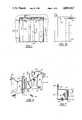
- FIG. 1is a front elevational view of a high-speed, horizontal folding door at the doorway of a freezer case or the like and showing the radiant heater portion of the invention
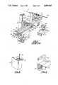
- FIG. 2is a partial, perspective view of suspension system of the prior art for a high-speed, horizontal folding door
- FIG. 3is an enlarged partial perspective view of the suspension system shown in FIG. 2;
- FIG. 4is an exploded, sectional perspective view taken along line 4--4 in FIG. 1 of the header portion of the invention
- FIG. 5is a sectional view taken along line 5--5 in FIG. 4 of the structure of FIG. 4 in assembled condition;
- FIG. 6is an exploded, partial perspective view of the door jamb of one embodiment of the invention.
- FIG. 7is a top plan view of the door jamb of the embodiment of FIG. 6 in assembled condition
- FIG. 8is a partial perspective view of another embodiment of the door jamb showing the heat tube partially withdrawn from the heat tube passageway;
- FIG. 9is an assembled, partial perspective view of the door jamb of FIG. 8 shown at a different angle
- FIG. 10is a side, elevational view of the door of FIG. 1.
- FIGS. 2-3generally illustrate a high-speed, horizontal folding door of the type generally contemplated for use in conjunction with the frost control system of the invention.
- a horizontal folding doorcombines the advantages of an overhead suspension system including a series of hinged, fan-foldable rack sections with a means for automatically opening and closing the door.
- Kleinproposed such a system in German Pat. No. 3,048,763 published Sept. 6, 1983. The entire contents of the German Pat. No. 3,048,763 are hereby expressly incorporated herein by reference. Doors of the Klein type have been manufactured and sold by Rytec Corporation, Jackson, Wis. since about 1985.
- a known folding door for use with the present inventionincludes a series of flexible transparent strips 1 having overlapping edge portions 1a each attached to a rack 3 consisting of jointed folding arms or sections 4, 5 and 6 which can be folded along a guide track 7.
- seal members 8a, 8b and 8care fitted to the top surface of each of folding arms 4, 5 and 6 to close the gap between folding arms 4, 5 and 6 and guide track 7 when the door is closed.
- Seal members 8a, 8b and 8cmay be either flexible elastomeric blades of appropriate length suitably secured to the upper surface of arms 4, 5 and 6 or flexible polymeric bristles of appropriate length suitably secured to the upper surface of arms 4, 5 and 6. Such blades or bristles are readily available from a number of sources known to workers in the art.
- Section 4 located nearest the doorway edgeis linked to a bearing bolt 9a attached to a side jamb 9 below guide track 7.
- a hinge pipe 10is pivotally connected to bearing bolt 9a and descends downwardly from bearing bolt 9a to pivotal attachment with a bearing plate 11.
- Hinge pipe 10is fitted with a flange 12 to which the outer edge of outer flexible transparent strip 1 is attached.
- a free end 4a of rack section 4is joined to second rack section 5 of double length which is attached at its center by a swivel joint 13 and a support rod 14 to a carriage 15 which comprises a vertically oriented plate having a series of rollers 15a mounted thereon. Rollers 15a engage the inner periphery of guide track 7, as illustrated in FIG. 3.
- Second rack section 5has an end 5a connected to third rack section 6 which moves in parallel with first rack section 4.
- An end portion 6a of rack section 6is attached by a swiveling joint 13a and an extended support rod 14a.
- a draw cable assembly 16 and a pair of draw rods 17a, 17bare disposed above guide track 7 and are connected to extended support rods 14a of rack section 6.
- Sprocket chains 18, 19 connected to draw rods 17a, 17bare guided by sprocket wheels 20, 21, at least one of which is powered by a suitable motor (not shown) to turn in either direction to open and close the door, respectively.
- Hinge pins 23 of hinges 22 connecting respective rack sections 4, 5 and 6are offset relative to an imaginary vertical longitudinal plane bisecting rack sections 5, 6. This allows sections 4, 5, 6 to fold parallel to each other in the manner shown in FIG. 3.
- Hinge connections 22may further have spring biased studs 25 which protrude from the end of at least one of each two adjoining sections 4, 5 and 5, 6 which assist hinging by exerting pressure on abutment end surface 26 of rack section end 5a, as illustrated in FIG. 3.
- folding doorhas features in common with this type of known folding door and tracking system.
- the inventionis readily applicable to folding doors having other types of specific mechanisms.
- FIGS. 4-5illustrate a preferred embodiment of the frost control system according to the present invention in which guide track 7 is attached to a front vertical support panel 32 which is integrally a part of a header 31.
- the headeris generally constructed of a heavy gauge sheet steel.
- heating elements 33a and 33bare placed in intimate contact with the interior surface of vertical support panel 32.
- the heating elementsshould be in the form of electrical copper tube heaters capable of heat output on the order of 10 watts per linear foot of heater.
- Such copper tube heatersare available from Easy Heat, Inc., New Carlisle, Ind.
- a heat resistant, highly closed cell insulating layer 37insures that heat generated by heat tubes 33a and 33b is directed into vertical panel 32 so that guide track 7 receives (by conduction) heat sufficient to keep it frost and ice free.
- insulating layer 37is a vinyl nitrile polymeric foam having a density of an average of 4.5 to 8.5 pounds per cubic feet, a water absorption by weight of about 0.1 pounds per square foot of cut surface, a high continuous temperature resistance of 150° F., a burn rate of zero inches per minute and better than 95% closed cells.
- Insulating layer 37preferably has a high heat resistance and low flammability because of its contact with heat tubes 33a and 33b in order to prevent risk of fire or other damage to either insulating layer 37 or to the door structure and its surroundings.
- High closed cell ratio and low water absorptionare preferred because the typical, high humidity, low temperature environment in which the present invention is intended to operate results in large amounts of condensate water forming on insulating layer 37. If high closed cell ratio and low water absorption are not present, the insulating layer 37 will absorb condensate water which will freeze in time in the interstices of the insulating layer 37 effectively eliminating its insulating capabilities.
- a high closed cell, low water absorption, high fire resistant material satisfactory for this useis available from Milwaukee Rubber Products of Menomonee Falls, Wis. and is known as Stock No. R1800FS.
- Insulating layer 37is held in place by steel retaining plate 38 which cooperates with the aforementioned stud 35 and clamping means 36 to clamp the insulating material in position against heat tubes 33a and 33b. It will be evident to workers skilled in the art that the resultant structure is a sandwich configuration as illustrated in FIG. 7 which effectively provides heat to the front outer surface of vertical support panel 32 of the header, thereby insuring absence of frost and ice from guide track 7 and the surrounding area adjacent to the folding area mechanism of the door.
- lower member 41 of header 31The outside of lower member 41 of header 31 is also subject to frosting or ice formation during use in a cold, damp environment. Hence, heat should be applied to lower member 41 as well.
- a fiber mesh heat mat material 42which is comprised of an open-weave fiber glass mesh 43 with a continuous insulated copper heating element 44 permanently bonded thereto in a serpentine formation and installed in header 31 so as to cover a substantial fraction all of the inner surface of lower member 41.
- Such fiber glass mesh heat mats 42are easily and rapidly installed and are available commercially in a variety of sizes and heating capacities, cause the heating element 44 to remain permanently in place (because it is bonded to mesh 43 which covers nearly all of the inside face of lower member 41 and is, hence, effectively immobilized), and have a minimal number of electrical connections as compared to conventional heat wire installations.
- Such fiber mesh heat matsare available from Easy Heat, Inc. of New Carlisle, Ind. and are known as Series G fiber mesh heat mats.
- matshave a heating capacity of approximately 40 watts/sq. ft to 60 watts/sq. ft. Such mats are designed for and are used extensively for embedding into asphalt or concrete for deicing driveways, airport runways and the like.
- Heat mat 42has behind it a closed cell second insulating layer 45 which is similar in its composition to insulating layer 37 earlier described.
- heat mat 42 and second insulating layer 45are held in place by a retention plate 46 which cooperates with an appropriate number of studs 47a and 47b and with fastening means 48a and 48b.
- the resultant structureis a sandwich of retention plate 46, second insulating layer 45 and heating mat 42 as illustrated in FIG. 5.
- Such structureprovides intimate, complete and uniform transfer of heat from the heating mat 42 to the entire exterior surface (by conduction) of lower member 41 of header 32 and, hence insures that no ice or frost will interfere with the movement of rack sections 4, 5 and 6 of the door.
- the resultant header structureprovides for a substantially frost-free and ice-free environment in most circumstances at a low consumption of electrical energy.
- a jamb 69 of the dooris formed of a first box section 62 and a second box section 63, which together form essentially a box shaped jamb 69 when fastened together by fasteners 64.
- a jamb heat tube 66which may be effectively in a serpentine form.
- Heat tube 66may be of the same heat tube material as previously described header heat tubes 33a and 33b which is sufficiently flexible to be formed into serpentine form with conventional hand forming techniques but sufficiently rigid to retain its shape during assembly and in service.
- Jamb heat tube 66is backed by a jamb insulating layer 67 which may effectively be of a material the same as previously described header insulating layers 37 and 45.
- the assembly of jamb heat tube 66 and insulating layer 67is held in intimate contact with the interior hinge wall 65 by a steel retention plate 68 in cooperation with an appropriate number of fasteners 70.
- the resultant structureis a sandwich of heat tube, insulating layer and retention plate as shown in FIG. 7.
- FIGS. 8 and 9Another embodiment of the invention which has fewer parts and important assembly advantages is illustrated in FIGS. 8 and 9.
- the jambis in the form of a welded box section 79 which has fabricated in it heat tube retention means which may effectively be in the form of an angle section 78 of steel welded into the interior wall of box section 79 on the side of box section 79 on which the door hinge pipe 10 will pass.
- Angle section 78should be sized so that a heat tube 73 will intimately contact both the interior wall of box section 79 and the interior wall of angle section 78 when heat tube 76 is inserted into the triangular channel formed by the combination of the wall of box section 79 and angle 78.
- Jamb insulating layer 77may be force fit into the open space of box section 79 immediately adjacent to angle section 78 and may be of the same closed cell material previously described.
- this embodimentis particularly advantageous when it is desired to install a door in a tunnel or other location where access to the outside of the jamb structure for installation or removal of the heat tube is not possible.
- the open top of the angle section 78permits heat tube 73 to be inserted or removed from the jamb structure from the top of the door so long as a suitable access port is provided in the header.
- FIGS. 4-5show a thermostat probe 51 in an appropriate location within the header remote from the header heating elements.
- probe 51is connected to a suitable, conventional thermostatic switch wired into the circuit of the header and jamb heaters to cycle them on and off.
- the inventorhas found that a surface temperature at this location of 62° F. is most typically adequate to insure a substantially frost and ice free header and jamb at reasonable energy consumption.
- the frost control system described abovemay be effectively supplemented to prevent frost formation on the downwardly descending curtain of the door and on the floor of the door opening by the installation of one or more electric infrared heaters 81 on the lower surface of the header on the "warm side" of the door between descending curtain panels 1 and a wall 102 of the freezer compartment as illustrated in FIGS. 1 and 10.
- Such electric infrared heaters 81are chosen to supply a sufficient amount of energy to prevent the formation of ice and frost on the descending curtain panel 1 and on the floor 103 of the door opening.
- the inventorhas discovered that in most installations, two electric infrared heating units of 3,000 watts each are sufficient to prevent ice and frost formation on the door curtain and on the floor of the door opening in environments down to -20° F.
- a suitable heater for such useis the Dayton 3E432 heater available from W. W. Grainger, Inc., Milwaukee, Wis.
Landscapes
- Engineering & Computer Science (AREA)
- Chemical & Material Sciences (AREA)
- Combustion & Propulsion (AREA)
- Physics & Mathematics (AREA)
- Mechanical Engineering (AREA)
- Thermal Sciences (AREA)
- General Engineering & Computer Science (AREA)
- Refrigerator Housings (AREA)
Abstract
Description
Claims (18)
Priority Applications (3)
| Application Number | Priority Date | Filing Date | Title |
|---|---|---|---|
| US07/144,572US4855567A (en) | 1988-01-15 | 1988-01-15 | Frost control system for high-speed horizontal folding doors |
| US07/259,689US4950869A (en) | 1988-01-15 | 1988-10-19 | Frost control system for high-speed mechanized doors |
| CA000588285ACA1309446C (en) | 1988-01-15 | 1989-01-13 | Frost control system for high-speed horizontal folding doors |
Applications Claiming Priority (1)
| Application Number | Priority Date | Filing Date | Title |
|---|---|---|---|
| US07/144,572US4855567A (en) | 1988-01-15 | 1988-01-15 | Frost control system for high-speed horizontal folding doors |
Related Child Applications (1)
| Application Number | Title | Priority Date | Filing Date |
|---|---|---|---|
| US07/259,689Continuation-In-PartUS4950869A (en) | 1988-01-15 | 1988-10-19 | Frost control system for high-speed mechanized doors |
Publications (1)
| Publication Number | Publication Date |
|---|---|
| US4855567Atrue US4855567A (en) | 1989-08-08 |
Family
ID=22509183
Family Applications (1)
| Application Number | Title | Priority Date | Filing Date |
|---|---|---|---|
| US07/144,572Expired - LifetimeUS4855567A (en) | 1988-01-15 | 1988-01-15 | Frost control system for high-speed horizontal folding doors |
Country Status (1)
| Country | Link |
|---|---|
| US (1) | US4855567A (en) |
Cited By (59)
| Publication number | Priority date | Publication date | Assignee | Title |
|---|---|---|---|---|
| US5025846A (en)* | 1988-07-07 | 1991-06-25 | Frommelt Industries, Inc. | High speed folding door |
| US5203175A (en)* | 1992-04-20 | 1993-04-20 | Rite-Hite Corporation | Frost control system |
| US5619613A (en)* | 1994-02-21 | 1997-04-08 | Otaki; Chizuko | Heating chamber with insulative shield panel and electric heating panels mounted on guard frames |
| US6119307A (en)* | 1998-08-07 | 2000-09-19 | United Dominion Industries, Inc. | Overhead door with a plunger assembly having a wear indicator and improved panel construction |
| US6247792B1 (en)* | 1997-07-15 | 2001-06-19 | Silverbrook Research Pty Ltd | PTFE surface shooting shuttered oscillating pressure ink jet printing mechanism |
| US6247790B1 (en)* | 1998-06-09 | 2001-06-19 | Silverbrook Research Pty Ltd | Inverted radial back-curling thermoelastic ink jet printing mechanism |
| US6283581B1 (en)* | 1998-06-08 | 2001-09-04 | Silverbrook Research Pty Ltd | Radial back-curling thermoelastic ink jet printing mechanism |
| US6303905B1 (en)* | 2000-08-25 | 2001-10-16 | Bask Technologies Llc | Heating element construction for floor warming systems |
| US6312107B1 (en)* | 1997-07-15 | 2001-11-06 | Silverbrook Research Pty Ltd | Thermoelastic bend actuator using PTFE corrugated heater ink jet printing mechanism |
| US6390603B1 (en)* | 1997-07-15 | 2002-05-21 | Silverbrook Research Pty Ltd | Buckle plate ink jet printing mechanism |
| US6408636B1 (en)* | 2000-10-16 | 2002-06-25 | Larry Backes | Method and apparatus for preventing ice build up around a freezer door |
| US6439695B2 (en) | 1998-06-08 | 2002-08-27 | Silverbrook Research Pty Ltd | Nozzle arrangement for an ink jet printhead including volume-reducing actuators |
| US20020137363A1 (en)* | 1998-08-24 | 2002-09-26 | Thakur Randhir P.S. | Methods to form electronic devices |
| US6474983B1 (en) | 2001-04-30 | 2002-11-05 | Edward S. Robbins | Heated industrial curtain |
| US6485123B2 (en) | 1997-07-15 | 2002-11-26 | Silverbrook Research Pty Ltd | Shutter ink jet |
| US6595429B1 (en) | 2002-04-03 | 2003-07-22 | Asi Technologies, Inc. | Apparatus and method for providing continuous real-time conditioned air curtain |
| US20040032461A1 (en)* | 1998-06-08 | 2004-02-19 | Kia Silverbrook | Flexible wall driven inkjet printhead nozzle |
| US20040135848A1 (en)* | 1997-07-15 | 2004-07-15 | Kia Silverbrook | Printing mechanism for a wide format pagewidth inkjet printer |
| US20040134128A1 (en)* | 2003-01-10 | 2004-07-15 | Jamison Door Company | Air heated, flexible door panel |
| US20040145630A1 (en)* | 1997-07-15 | 2004-07-29 | Kia Silverbrook | Ink supply arrangement for a printing mechanism of a wide format pagewidth inkjet printer |
| US20040247362A1 (en)* | 1997-07-15 | 2004-12-09 | King Tobin Allen | Keyboard |
| US20050007418A1 (en)* | 1997-07-15 | 2005-01-13 | Kia Silverbrook | Printhead assembly arrangement for a wide format pagewidth inkjet printer |
| US20050041086A1 (en)* | 1997-07-15 | 2005-02-24 | King Tobin Allen | Pagewidth printer that includes a computer-connectable keyboard |
| US20050083392A1 (en)* | 1997-07-15 | 2005-04-21 | Kia Silverbrook | Wide format pagewidth inkjet printer |
| US20050157080A1 (en)* | 1997-07-15 | 2005-07-21 | Kia Silverbrook | Printing mechanism having wide format printing zone |
| US20050197057A1 (en)* | 2004-03-02 | 2005-09-08 | Rohrer Stephen R. | Air curtain doorway |
| US20060090401A1 (en)* | 2003-01-10 | 2006-05-04 | Jamison Door Company | Air heated, flexible door panel |
| US20060283850A1 (en)* | 2005-06-15 | 2006-12-21 | Jerry Davey | Automated glass entrance door assembly for walk-in coolers |
| WO2006115501A3 (en)* | 2005-04-27 | 2007-01-11 | Carrier Corp | Refrigerator case wall structure |
| US20070040867A1 (en)* | 1997-07-15 | 2007-02-22 | Silverbrook Research Pty Ltd | Nozzle assembly with heat deflected actuator |
| US7185463B2 (en) | 2003-12-30 | 2007-03-06 | Rite-Hite Holding Corporation | Water runoff deflector for a vehicle at a loading dock |
| US20080104902A1 (en)* | 2006-11-07 | 2008-05-08 | Rite-Hite Holding Corporation | Low profile support panel for a dock seal |
| US20080129807A1 (en)* | 1998-11-09 | 2008-06-05 | Silverbrook Research Pty Ltd | Tamper proof print cartridge for a video game console |
| US20090073236A1 (en)* | 2000-05-23 | 2009-03-19 | Silverbrook Research Pty Ltd | Variable-volume nozzle arrangement |
| US20100277531A1 (en)* | 1997-07-15 | 2010-11-04 | Silverbrook Research Pty Ltd | Printer having processor for high volume printing |
| US7836878B1 (en)* | 2006-05-08 | 2010-11-23 | Agha Nazih S | Appliance heat isolation system for attachment to a vent hood |
| US20100295903A1 (en)* | 1997-07-15 | 2010-11-25 | Silverbrook Research Pty Ltd | Ink ejection nozzle arrangement for inkjet printer |
| US20110011003A1 (en)* | 2005-10-28 | 2011-01-20 | Vogel Lynn D | Flexible door with rigid insulation |
| US7950777B2 (en) | 1997-07-15 | 2011-05-31 | Silverbrook Research Pty Ltd | Ejection nozzle assembly |
| US8020970B2 (en) | 1997-07-15 | 2011-09-20 | Silverbrook Research Pty Ltd | Printhead nozzle arrangements with magnetic paddle actuators |
| US8025366B2 (en) | 1997-07-15 | 2011-09-27 | Silverbrook Research Pty Ltd | Inkjet printhead with nozzle layer defining etchant holes |
| US8029102B2 (en) | 1997-07-15 | 2011-10-04 | Silverbrook Research Pty Ltd | Printhead having relatively dimensioned ejection ports and arms |
| US8029101B2 (en) | 1997-07-15 | 2011-10-04 | Silverbrook Research Pty Ltd | Ink ejection mechanism with thermal actuator coil |
| US8061812B2 (en) | 1997-07-15 | 2011-11-22 | Silverbrook Research Pty Ltd | Ejection nozzle arrangement having dynamic and static structures |
| US8075104B2 (en) | 1997-07-15 | 2011-12-13 | Sliverbrook Research Pty Ltd | Printhead nozzle having heater of higher resistance than contacts |
| US8083326B2 (en) | 1997-07-15 | 2011-12-27 | Silverbrook Research Pty Ltd | Nozzle arrangement with an actuator having iris vanes |
| US8113629B2 (en) | 1997-07-15 | 2012-02-14 | Silverbrook Research Pty Ltd. | Inkjet printhead integrated circuit incorporating fulcrum assisted ink ejection actuator |
| US8123336B2 (en) | 1997-07-15 | 2012-02-28 | Silverbrook Research Pty Ltd | Printhead micro-electromechanical nozzle arrangement with motion-transmitting structure |
| US20150034067A1 (en)* | 2012-02-02 | 2015-02-05 | Engineered Plastics Inc. | Frost resistant surface |
| WO2015077094A1 (en)* | 2013-11-20 | 2015-05-28 | Rytec Corporation | Turbo seal insulated heat fin |
| US10323875B2 (en) | 2015-07-27 | 2019-06-18 | Illinois Tool Works Inc. | System and method of controlling refrigerator and freezer units to reduce consumed energy |
| US11002065B2 (en) | 2018-02-26 | 2021-05-11 | Asi Doors, Inc. | Sealing system for a conditioned door threshold |
| US11116333B2 (en) | 2019-05-07 | 2021-09-14 | Carrier Corporation | Refrigerated display cabinet including microchannel heat exchangers |
| US11221174B2 (en)* | 2020-02-05 | 2022-01-11 | Peter M. Osgard | Refrigeration door system and door assembly with defrosting and related methods |
| US11274873B2 (en)* | 2014-12-09 | 2022-03-15 | Bsh Hausgeraete Gmbh | Domestic refrigeration appliance device |
| US11371285B2 (en) | 2018-05-25 | 2022-06-28 | Overhead Door Corporation | Rolling door guide area heating method and system |
| US11415358B1 (en) | 2019-06-20 | 2022-08-16 | Illinois Tool Works Inc. | Adaptive perimeter heating in refrigerator and freezer units |
| US11559147B2 (en) | 2019-05-07 | 2023-01-24 | Carrier Corporation | Refrigerated display cabinet utilizing a radial cross flow fan |
| US11906235B2 (en) | 2020-02-05 | 2024-02-20 | Peter M. Osgard | Refrigeration door system and door assembly with defrosting and related methods |
Citations (33)
| Publication number | Priority date | Publication date | Assignee | Title |
|---|---|---|---|---|
| US1992011A (en)* | 1933-02-04 | 1935-02-19 | Gen Electric | Refrigerator cabinet |
| US2238511A (en)* | 1940-03-12 | 1941-04-15 | Curtis H Thaxter | Refrigerated cabinet |
| US2420240A (en)* | 1945-03-13 | 1947-05-06 | William B Haggerty | Means for the prevention of frost on refrigerator doors |
| US2460469A (en)* | 1946-12-07 | 1949-02-01 | Frex O Mat Corp | Refrigerator having a door heating device |
| US2493125A (en)* | 1945-02-05 | 1950-01-03 | Calpat Corp | Door-mounted electric space heater |
| US2731804A (en)* | 1956-01-24 | Frost preventer for freezer doors | ||
| US2809402A (en)* | 1953-01-05 | 1957-10-15 | S G Anderson | Door structure for refrigerators |
| US2858408A (en)* | 1957-10-25 | 1958-10-28 | Louis F Barroero | Refrigerated freezer cabinets having heated door frames and doors therefor |
| US2984085A (en)* | 1960-04-15 | 1961-05-16 | Warren Company Inc | Walk-in cooler apparatus |
| US3064110A (en)* | 1960-02-19 | 1962-11-13 | R M P Ind Ltd | Heated frame element for door and window constructions |
| US3135100A (en)* | 1961-10-23 | 1964-06-02 | Thomas D Taylor | Apparatus for preventing freeze-up of refrigerator doors |
| US3186185A (en)* | 1963-01-03 | 1965-06-01 | Mccray Refrigerator Company In | Refrigerated display unit |
| US3254503A (en)* | 1964-12-29 | 1966-06-07 | Clark Equipment Co | Frost preventer for freezer apparatus |
| US3449925A (en)* | 1968-01-24 | 1969-06-17 | Louis F Barroero | Refrigerator with heated door frame |
| US3462885A (en)* | 1967-10-17 | 1969-08-26 | Miller Bros | Safety edge for a door |
| US3612821A (en)* | 1970-11-16 | 1971-10-12 | Anthony S Mfg Co | Door frame construction |
| US3697723A (en)* | 1970-12-24 | 1972-10-10 | Ardco Inc | Mullion construction for refrigerator door frame |
| US3869873A (en)* | 1974-05-20 | 1975-03-11 | Elliott Williams Company Inc | Door structure for large freezer |
| US4080764A (en)* | 1976-06-25 | 1978-03-28 | The Vollrath Company | Door jamb with isolated heat strip |
| US4083395A (en)* | 1976-08-20 | 1978-04-11 | Romano Paul L | Acoustic drape |
| US4109484A (en)* | 1977-03-03 | 1978-08-29 | Sullivan Company | Thermal protective barrier for open refrigerated compartment |
| GB1554159A (en)* | 1976-06-18 | 1979-10-17 | Bestobell Home Prod Ltd | Curtain assemblies |
| US4274467A (en)* | 1979-03-23 | 1981-06-23 | Kenney Manufacturing Company | Drapery and support combination |
| US4289190A (en)* | 1979-01-26 | 1981-09-15 | Dynaforce Corporation | Plastic strip closures and methods of protecting the same |
| US4313485A (en)* | 1979-11-13 | 1982-02-02 | Bsl Corporation | Transparent access curtain for coolers and the like |
| GB2080379A (en)* | 1980-07-12 | 1982-02-03 | Sills Geoffrey Alan | Doors |
| US4335777A (en)* | 1978-12-18 | 1982-06-22 | Societe Anonyme: "Mavil" | Multiple strips doors |
| DE3048763A1 (en)* | 1980-12-23 | 1982-08-19 | Labex GmbH Import-Export Industrieanlagen und Fördertechnik, 5340 Bad Honnef | Industrial doorway transparent plastics strip curtain - has folding suspension rod system on carriage and roller movable along guide-rail |
| US4355678A (en)* | 1981-03-03 | 1982-10-26 | Acoustic Standards | Acoustic strip curtain |
| US4388961A (en)* | 1980-10-21 | 1983-06-21 | Albert Reiff Kg | Strip-type door |
| US4420027A (en)* | 1979-11-13 | 1983-12-13 | Bsl Corporation | Transparent access curtain for coolers and the like |
| US4448232A (en)* | 1982-05-03 | 1984-05-15 | Erect-A-Tube, Inc. | Bi-fold door assembly |
| US4449270A (en)* | 1980-02-08 | 1984-05-22 | Henri Brabant | Hanging device for curtain straps out of resilient plastic material for closing building openings |
- 1988
- 1988-01-15USUS07/144,572patent/US4855567A/ennot_activeExpired - Lifetime
Patent Citations (33)
| Publication number | Priority date | Publication date | Assignee | Title |
|---|---|---|---|---|
| US2731804A (en)* | 1956-01-24 | Frost preventer for freezer doors | ||
| US1992011A (en)* | 1933-02-04 | 1935-02-19 | Gen Electric | Refrigerator cabinet |
| US2238511A (en)* | 1940-03-12 | 1941-04-15 | Curtis H Thaxter | Refrigerated cabinet |
| US2493125A (en)* | 1945-02-05 | 1950-01-03 | Calpat Corp | Door-mounted electric space heater |
| US2420240A (en)* | 1945-03-13 | 1947-05-06 | William B Haggerty | Means for the prevention of frost on refrigerator doors |
| US2460469A (en)* | 1946-12-07 | 1949-02-01 | Frex O Mat Corp | Refrigerator having a door heating device |
| US2809402A (en)* | 1953-01-05 | 1957-10-15 | S G Anderson | Door structure for refrigerators |
| US2858408A (en)* | 1957-10-25 | 1958-10-28 | Louis F Barroero | Refrigerated freezer cabinets having heated door frames and doors therefor |
| US3064110A (en)* | 1960-02-19 | 1962-11-13 | R M P Ind Ltd | Heated frame element for door and window constructions |
| US2984085A (en)* | 1960-04-15 | 1961-05-16 | Warren Company Inc | Walk-in cooler apparatus |
| US3135100A (en)* | 1961-10-23 | 1964-06-02 | Thomas D Taylor | Apparatus for preventing freeze-up of refrigerator doors |
| US3186185A (en)* | 1963-01-03 | 1965-06-01 | Mccray Refrigerator Company In | Refrigerated display unit |
| US3254503A (en)* | 1964-12-29 | 1966-06-07 | Clark Equipment Co | Frost preventer for freezer apparatus |
| US3462885A (en)* | 1967-10-17 | 1969-08-26 | Miller Bros | Safety edge for a door |
| US3449925A (en)* | 1968-01-24 | 1969-06-17 | Louis F Barroero | Refrigerator with heated door frame |
| US3612821A (en)* | 1970-11-16 | 1971-10-12 | Anthony S Mfg Co | Door frame construction |
| US3697723A (en)* | 1970-12-24 | 1972-10-10 | Ardco Inc | Mullion construction for refrigerator door frame |
| US3869873A (en)* | 1974-05-20 | 1975-03-11 | Elliott Williams Company Inc | Door structure for large freezer |
| GB1554159A (en)* | 1976-06-18 | 1979-10-17 | Bestobell Home Prod Ltd | Curtain assemblies |
| US4080764A (en)* | 1976-06-25 | 1978-03-28 | The Vollrath Company | Door jamb with isolated heat strip |
| US4083395A (en)* | 1976-08-20 | 1978-04-11 | Romano Paul L | Acoustic drape |
| US4109484A (en)* | 1977-03-03 | 1978-08-29 | Sullivan Company | Thermal protective barrier for open refrigerated compartment |
| US4335777A (en)* | 1978-12-18 | 1982-06-22 | Societe Anonyme: "Mavil" | Multiple strips doors |
| US4289190A (en)* | 1979-01-26 | 1981-09-15 | Dynaforce Corporation | Plastic strip closures and methods of protecting the same |
| US4274467A (en)* | 1979-03-23 | 1981-06-23 | Kenney Manufacturing Company | Drapery and support combination |
| US4420027A (en)* | 1979-11-13 | 1983-12-13 | Bsl Corporation | Transparent access curtain for coolers and the like |
| US4313485A (en)* | 1979-11-13 | 1982-02-02 | Bsl Corporation | Transparent access curtain for coolers and the like |
| US4449270A (en)* | 1980-02-08 | 1984-05-22 | Henri Brabant | Hanging device for curtain straps out of resilient plastic material for closing building openings |
| GB2080379A (en)* | 1980-07-12 | 1982-02-03 | Sills Geoffrey Alan | Doors |
| US4388961A (en)* | 1980-10-21 | 1983-06-21 | Albert Reiff Kg | Strip-type door |
| DE3048763A1 (en)* | 1980-12-23 | 1982-08-19 | Labex GmbH Import-Export Industrieanlagen und Fördertechnik, 5340 Bad Honnef | Industrial doorway transparent plastics strip curtain - has folding suspension rod system on carriage and roller movable along guide-rail |
| US4355678A (en)* | 1981-03-03 | 1982-10-26 | Acoustic Standards | Acoustic strip curtain |
| US4448232A (en)* | 1982-05-03 | 1984-05-15 | Erect-A-Tube, Inc. | Bi-fold door assembly |
Non-Patent Citations (2)
| Title |
|---|
| Electrical Construction and Maintenance, "Infrared Quartz Lamps", vol. 67, No. 7, Jul. 1968. |
| Electrical Construction and Maintenance, Infrared Quartz Lamps , vol. 67, No. 7, Jul. 1968.* |
Cited By (279)
| Publication number | Priority date | Publication date | Assignee | Title |
|---|---|---|---|---|
| US5025846A (en)* | 1988-07-07 | 1991-06-25 | Frommelt Industries, Inc. | High speed folding door |
| US5203175A (en)* | 1992-04-20 | 1993-04-20 | Rite-Hite Corporation | Frost control system |
| WO1993021486A1 (en)* | 1992-04-20 | 1993-10-28 | Rite-Hite Corporation | Frost control system |
| US5329781A (en)* | 1992-04-20 | 1994-07-19 | Rite-Hite Corporation | Frost control system |
| GB2278427A (en)* | 1992-04-20 | 1994-11-30 | Rite Hite Corp | Frost control system |
| GB2278427B (en)* | 1992-04-20 | 1996-05-15 | Rite Hite Corp | Frost control system |
| US5619613A (en)* | 1994-02-21 | 1997-04-08 | Otaki; Chizuko | Heating chamber with insulative shield panel and electric heating panels mounted on guard frames |
| US7585050B2 (en) | 1997-07-15 | 2009-09-08 | Silverbrook Research Pty Ltd | Print assembly and printer having wide printing zone |
| US7591534B2 (en) | 1997-07-15 | 2009-09-22 | Silverbrook Research Pty Ltd | Wide format print assembly having CMOS drive circuitry |
| US8419165B2 (en) | 1997-07-15 | 2013-04-16 | Zamtec Ltd | Printhead module for wide format pagewidth inkjet printer |
| US8408679B2 (en) | 1997-07-15 | 2013-04-02 | Zamtec Ltd | Printhead having CMOS drive circuitry |
| US8123336B2 (en) | 1997-07-15 | 2012-02-28 | Silverbrook Research Pty Ltd | Printhead micro-electromechanical nozzle arrangement with motion-transmitting structure |
| US6312107B1 (en)* | 1997-07-15 | 2001-11-06 | Silverbrook Research Pty Ltd | Thermoelastic bend actuator using PTFE corrugated heater ink jet printing mechanism |
| US6390603B1 (en)* | 1997-07-15 | 2002-05-21 | Silverbrook Research Pty Ltd | Buckle plate ink jet printing mechanism |
| US8113629B2 (en) | 1997-07-15 | 2012-02-14 | Silverbrook Research Pty Ltd. | Inkjet printhead integrated circuit incorporating fulcrum assisted ink ejection actuator |
| US6425657B2 (en) | 1997-07-15 | 2002-07-30 | Silverbrook Research Pty Ltd | Ink jet with coiled actuator |
| US8083326B2 (en) | 1997-07-15 | 2011-12-27 | Silverbrook Research Pty Ltd | Nozzle arrangement with an actuator having iris vanes |
| US8075104B2 (en) | 1997-07-15 | 2011-12-13 | Sliverbrook Research Pty Ltd | Printhead nozzle having heater of higher resistance than contacts |
| US8061812B2 (en) | 1997-07-15 | 2011-11-22 | Silverbrook Research Pty Ltd | Ejection nozzle arrangement having dynamic and static structures |
| US6485123B2 (en) | 1997-07-15 | 2002-11-26 | Silverbrook Research Pty Ltd | Shutter ink jet |
| US8029101B2 (en) | 1997-07-15 | 2011-10-04 | Silverbrook Research Pty Ltd | Ink ejection mechanism with thermal actuator coil |
| US8029102B2 (en) | 1997-07-15 | 2011-10-04 | Silverbrook Research Pty Ltd | Printhead having relatively dimensioned ejection ports and arms |
| US8025366B2 (en) | 1997-07-15 | 2011-09-27 | Silverbrook Research Pty Ltd | Inkjet printhead with nozzle layer defining etchant holes |
| US8020970B2 (en) | 1997-07-15 | 2011-09-20 | Silverbrook Research Pty Ltd | Printhead nozzle arrangements with magnetic paddle actuators |
| US7950777B2 (en) | 1997-07-15 | 2011-05-31 | Silverbrook Research Pty Ltd | Ejection nozzle assembly |
| US7934796B2 (en) | 1997-07-15 | 2011-05-03 | Silverbrook Research Pty Ltd | Wide format printer having high speed printhead |
| US7914114B2 (en) | 1997-07-15 | 2011-03-29 | Silverbrook Research Pty Ltd | Print assembly having high speed printhead |
| US7845869B2 (en) | 1997-07-15 | 2010-12-07 | Silverbrook Research Pty Ltd | Computer keyboard with internal printer |
| US20100295903A1 (en)* | 1997-07-15 | 2010-11-25 | Silverbrook Research Pty Ltd | Ink ejection nozzle arrangement for inkjet printer |
| US20100277531A1 (en)* | 1997-07-15 | 2010-11-04 | Silverbrook Research Pty Ltd | Printer having processor for high volume printing |
| US20040085402A1 (en)* | 1997-07-15 | 2004-05-06 | Kia Silverbrook | Micro-electromechanical valve assembly |
| US20040084405A1 (en)* | 1997-07-15 | 2004-05-06 | Kia Silverbrook | Method of fabricating an inkjet printhead chip for use with a pulsating pressure ink supply |
| US20100026763A1 (en)* | 1997-07-15 | 2010-02-04 | Silverbrook Research Pty Ltd | Printhead having cmos drive circuitry |
| US20090303286A1 (en)* | 1997-07-15 | 2009-12-10 | Silverbrook Research Pty Ltd | Printhead For Wide Format High Resolution Printing |
| US20040135848A1 (en)* | 1997-07-15 | 2004-07-15 | Kia Silverbrook | Printing mechanism for a wide format pagewidth inkjet printer |
| US20090295868A1 (en)* | 1997-07-15 | 2009-12-03 | Silverbrook Research Pty Ltd | Printhead Having Ejection Nozzles Over Wide Printing Zone |
| US20040145630A1 (en)* | 1997-07-15 | 2004-07-29 | Kia Silverbrook | Ink supply arrangement for a printing mechanism of a wide format pagewidth inkjet printer |
| US20040145756A1 (en)* | 1997-07-15 | 2004-07-29 | Kia Silverbrook | Image processing apparatus for a printing mechanism of a wide format pagewidth inkjet printer |
| US20040165034A1 (en)* | 1997-07-15 | 2004-08-26 | Kia Silverbrook | Printing mechanism for a wide format pagewidth inkjet printer |
| US6783217B2 (en) | 1997-07-15 | 2004-08-31 | Silverbrook Research Pty Ltd | Micro-electromechanical valve assembly |
| US6786570B2 (en) | 1997-07-15 | 2004-09-07 | Silverbrook Research Pty Ltd | Ink supply arrangement for a printing mechanism of a wide format pagewidth inkjet printer |
| US20070097194A1 (en)* | 1997-07-15 | 2007-05-03 | Silverbrook Research Pty Ltd | Printer with serially arranged printhead modules for wide format printing |
| US20040227789A1 (en)* | 1997-07-15 | 2004-11-18 | Kia Silverbrook | Inkjet printhead chip for use with a pulsating pressure ink supply |
| US20040247362A1 (en)* | 1997-07-15 | 2004-12-09 | King Tobin Allen | Keyboard |
| US20040257403A1 (en)* | 1997-07-15 | 2004-12-23 | Silverbrook Research Pty Ltd | Micro-electromechanical valve shutter assembly |
| US20050007418A1 (en)* | 1997-07-15 | 2005-01-13 | Kia Silverbrook | Printhead assembly arrangement for a wide format pagewidth inkjet printer |
| US6848780B2 (en) | 1997-07-15 | 2005-02-01 | Sivlerbrook Research Pty Ltd | Printing mechanism for a wide format pagewidth inkjet printer |
| US20050024429A1 (en)* | 1997-07-15 | 2005-02-03 | Kia Silverbrook | Print assembly for a wide format pagewidth inkjet printer, having a plurality of printhead chips |
| US6247792B1 (en)* | 1997-07-15 | 2001-06-19 | Silverbrook Research Pty Ltd | PTFE surface shooting shuttered oscillating pressure ink jet printing mechanism |
| US20050036001A1 (en)* | 1997-07-15 | 2005-02-17 | Silverbrook Research Pty Ltd | Actuator for a micro-electromechanical valve assembly |
| US7217048B2 (en) | 1997-07-15 | 2007-05-15 | Silverbrook Research Pty Ltd | Pagewidth printer and computer keyboard combination |
| US20050041086A1 (en)* | 1997-07-15 | 2005-02-24 | King Tobin Allen | Pagewidth printer that includes a computer-connectable keyboard |
| US20050063759A1 (en)* | 1997-07-15 | 2005-03-24 | King Tobin Allen | Printer and keyboard combination |
| US20090213179A1 (en)* | 1997-07-15 | 2009-08-27 | Silverbrook Research Pty Ltd | Wide format printer having high speed printhead |
| US20050083392A1 (en)* | 1997-07-15 | 2005-04-21 | Kia Silverbrook | Wide format pagewidth inkjet printer |
| US20090213180A1 (en)* | 1997-07-15 | 2009-08-27 | Silverbrook Research Pty Ltd | Print assembly having high speed printhead |
| US7571983B2 (en) | 1997-07-15 | 2009-08-11 | Silverbrook Research Pty Ltd | Wide-format printer with a pagewidth printhead assembly |
| US7566110B2 (en) | 1997-07-15 | 2009-07-28 | Silverbrook Research Pty Ltd | Printhead module for a wide format pagewidth inkjet printer |
| US20090141054A1 (en)* | 1997-07-15 | 2009-06-04 | Silverbrook Research Pty Ltd. | Print engine controller for an inkjet printhead |
| US7537301B2 (en) | 1997-07-15 | 2009-05-26 | Silverbrook Research Pty Ltd. | Wide format print assembly having high speed printhead |
| US6916082B2 (en) | 1997-07-15 | 2005-07-12 | Silverbrook Research Pty Ltd | Printing mechanism for a wide format pagewidth inkjet printer |
| US20050157144A1 (en)* | 1997-07-15 | 2005-07-21 | Kia Silverbrook | Print media transport assembly |
| US7524026B2 (en) | 1997-07-15 | 2009-04-28 | Silverbrook Research Pty Ltd | Nozzle assembly with heat deflected actuator |
| US20050162465A1 (en)* | 1997-07-15 | 2005-07-28 | Kia Silverbrook | Printing mechanism having elongate modular structure |
| US7517164B2 (en) | 1997-07-15 | 2009-04-14 | Silverbrook Research Pty Ltd | Computer keyboard with a planar member and endless belt feed mechanism |
| US6929352B2 (en) | 1997-07-15 | 2005-08-16 | Silverbrook Research Pty Ltd | Inkjet printhead chip for use with a pulsating pressure ink supply |
| US7506961B2 (en) | 1997-07-15 | 2009-03-24 | Silverbrook Research Pty Ltd | Printer with serially arranged printhead modules for wide format printing |
| US7407261B2 (en) | 1997-07-15 | 2008-08-05 | Silverbrook Research Pty Ltd | Image processing apparatus for a printing mechanism of a wide format pagewidth inkjet printer |
| US7367729B2 (en) | 1997-07-15 | 2008-05-06 | Silverbrook Research Pty Ltd | Printer within a computer keyboard |
| US20050226667A1 (en)* | 1997-07-15 | 2005-10-13 | Silverbrook Research Pty Ltd. | Pagewidth printer and computer keyboard combination |
| US20050225607A1 (en)* | 1997-07-15 | 2005-10-13 | Silverbrook Research Pty Ltd. | Printer having a printhead with an inkjet printhead chip for use with a pulsating pressure ink supply |
| US20050226668A1 (en)* | 1997-07-15 | 2005-10-13 | Silverbrook Research Pty Ltd | Keyboard for a computer system |
| US20050232675A1 (en)* | 1997-07-15 | 2005-10-20 | Silverbrook Research Pty Ltd | Printer within a computer keyboard |
| US7357488B2 (en) | 1997-07-15 | 2008-04-15 | Silverbrook Research Pty Ltd | Nozzle assembly incorporating a shuttered actuation mechanism |
| US7341672B2 (en) | 1997-07-15 | 2008-03-11 | Silverbrook Research Pty Ltd | Method of fabricating printhead for ejecting ink supplied under pulsed pressure |
| US7325918B2 (en) | 1997-07-15 | 2008-02-05 | Silverbrook Research Pty Ltd | Print media transport assembly |
| US20080019756A1 (en)* | 1997-07-15 | 2008-01-24 | Silverbrook Research Pty Ltd | Computer keyboard with a planar member and endless belt feed mechanism |
| US20070292185A1 (en)* | 1997-07-15 | 2007-12-20 | Silverbrook Research Pty Ltd | Computer Keyboard With Internal Printer |
| US20070285452A1 (en)* | 1997-07-15 | 2007-12-13 | Silverbrook Research Pty Ltd | Wide format print assembly having high speed printhead |
| US7278796B2 (en) | 1997-07-15 | 2007-10-09 | Silverbrook Research Pty Ltd | Keyboard for a computer system |
| US7270492B2 (en) | 1997-07-15 | 2007-09-18 | Silverbrook Research Pty Ltd | Computer system having integrated printer and keyboard |
| US7270399B2 (en) | 1997-07-15 | 2007-09-18 | Silverbrook Research Pty Ltd | Printhead for use with a pulsating pressure ink supply |
| US20070211113A1 (en)* | 1997-07-15 | 2007-09-13 | Silverbrook Research Pty. Ltd. | Wide format print assembly having cmos drive circuitry |
| US20070211093A1 (en)* | 1997-07-15 | 2007-09-13 | Silverbrook Research Pty Ltd | Wide format print assembly having high resolution printhead |
| US20070206052A1 (en)* | 1997-07-15 | 2007-09-06 | Silverbrook Research Pty Ltd | Print assembly and printer having wide printing zone |
| US6986613B2 (en) | 1997-07-15 | 2006-01-17 | Silverbrook Research Pty Ltd | Keyboard |
| US20060012635A1 (en)* | 1997-07-15 | 2006-01-19 | Silverbrook Research Pty Ltd | Print assembly for a wide format printer |
| US6988841B2 (en) | 1997-07-15 | 2006-01-24 | Silverbrook Research Pty Ltd. | Pagewidth printer that includes a computer-connectable keyboard |
| US7246881B2 (en) | 1997-07-15 | 2007-07-24 | Silverbrook Research Pty Ltd | Printhead assembly arrangement for a wide format pagewidth inkjet printer |
| US6994420B2 (en) | 1997-07-15 | 2006-02-07 | Silverbrook Research Pty Ltd | Print assembly for a wide format pagewidth inkjet printer, having a plurality of printhead chips |
| US7226145B2 (en) | 1997-07-15 | 2007-06-05 | Silverbrook Research Pty Ltd | Micro-electromechanical valve shutter assembly |
| US7008041B2 (en) | 1997-07-15 | 2006-03-07 | Silverbrook Research Pty Ltd | Printing mechanism having elongate modular structure |
| US7011390B2 (en) | 1997-07-15 | 2006-03-14 | Silverbrook Research Pty Ltd | Printing mechanism having wide format printing zone |
| US20060055756A1 (en)* | 1997-07-15 | 2006-03-16 | Silverbrook Research Pty Ltd | Wide format printer with a plurality of printhead integrated circuits |
| US20050157080A1 (en)* | 1997-07-15 | 2005-07-21 | Kia Silverbrook | Printing mechanism having wide format printing zone |
| US7588316B2 (en) | 1997-07-15 | 2009-09-15 | Silverbrook Research Pty Ltd | Wide format print assembly having high resolution printhead |
| US7044584B2 (en) | 1997-07-15 | 2006-05-16 | Silverbrook Research Pty Ltd | Wide format pagewidth inkjet printer |
| US20060109307A1 (en)* | 1997-07-15 | 2006-05-25 | Silverbrook Research Pty Ltd | Wide-format print engine with a pagewidth ink reservoir assembly |
| US7077588B2 (en) | 1997-07-15 | 2006-07-18 | Silverbrook Research Pty Ltd | Printer and keyboard combination |
| US20090267991A1 (en)* | 1997-07-15 | 2009-10-29 | Silverbrook Research Pty Ltd | Printhead module for wide format pagewidth inkjet printer |
| US20070070124A1 (en)* | 1997-07-15 | 2007-03-29 | Silverbrook Research Pty Ltd | Nozzle assembly incorporating a shuttered actuation mechanism |
| US20070040867A1 (en)* | 1997-07-15 | 2007-02-22 | Silverbrook Research Pty Ltd | Nozzle assembly with heat deflected actuator |
| US20070029278A1 (en)* | 1997-07-15 | 2007-02-08 | Silverbrook Research Pty Ltd | Method of fabricating printhead for ejecting ink supplied under pulsed pressure |
| US7172265B2 (en) | 1997-07-15 | 2007-02-06 | Silverbrook Research Pty Ltd | Print assembly for a wide format printer |
| US20060227184A1 (en)* | 1997-07-15 | 2006-10-12 | Silverbrook Research Pty Ltd | Micro-electromechanical valve having transformable valve actuator |
| US20070013742A1 (en)* | 1997-07-15 | 2007-01-18 | Silverbrook Research Pty Ltd | Printhead for use with a pulsating pressure ink supply |
| US7159965B2 (en) | 1997-07-15 | 2007-01-09 | Silverbrook Research Pty Ltd | Wide format printer with a plurality of printhead integrated circuits |
| US7152960B2 (en) | 1997-07-15 | 2006-12-26 | Silverbrook Research Pty Ltd | Micro-electromechanical valve having transformable valve actuator |
| US20060256158A1 (en)* | 1997-07-15 | 2006-11-16 | Silverbrook Research Pty Ltd | Printhead module for a wide format pagewidth inkjet printer |
| US7152949B2 (en) | 1997-07-15 | 2006-12-26 | Silverbrook Research Pty Ltd | Wide-format print engine with a pagewidth ink reservoir assembly |
| US7140719B2 (en) | 1997-07-15 | 2006-11-28 | Silverbrook Research Pty Ltd | Actuator for a micro-electromechanical valve assembly |
| US7144098B2 (en) | 1997-07-15 | 2006-12-05 | Silverbrook Research Pty Ltd | Printer having a printhead with an inkjet printhead chip for use with a pulsating pressure ink supply |
| US7147791B2 (en) | 1997-07-15 | 2006-12-12 | Silverbrook Research Pty Ltd | Method of fabricating an injket printhead chip for use with a pulsating pressure ink supply |
| US7147302B2 (en) | 1997-07-15 | 2006-12-12 | Silverbrook Researh Pty Ltd | Nozzle assembly |
| US7325904B2 (en) | 1998-06-08 | 2008-02-05 | Silverbrook Research Pty Ltd | Printhead having multiple thermal actuators for ink ejection |
| US20050116993A1 (en)* | 1998-06-08 | 2005-06-02 | Kia Silverbrook | Printhead chip that incorporates nozzle chamber reduction mechanisms |
| US7140720B2 (en) | 1998-06-08 | 2006-11-28 | Silverbrook Research Pty Ltd | Micro-electromechanical fluid ejection device having actuator mechanisms located in chamber roof structure |
| US6283581B1 (en)* | 1998-06-08 | 2001-09-04 | Silverbrook Research Pty Ltd | Radial back-curling thermoelastic ink jet printing mechanism |
| US6439695B2 (en) | 1998-06-08 | 2002-08-27 | Silverbrook Research Pty Ltd | Nozzle arrangement for an ink jet printhead including volume-reducing actuators |
| US6488358B2 (en) | 1998-06-08 | 2002-12-03 | Silverbrook Research Pty Ltd | Ink jet with multiple actuators per nozzle |
| US6505912B2 (en) | 1998-06-08 | 2003-01-14 | Silverbrook Research Pty Ltd | Ink jet nozzle arrangement |
| US20060232629A1 (en)* | 1998-06-08 | 2006-10-19 | Silverbrook Research Pty Ltd | Inkjet nozzle that incorporates volume-reduction actuation |
| US20070008374A1 (en)* | 1998-06-08 | 2007-01-11 | Silverbrook Research Pty Ltd | Nozzle arrangement for an inkjet printing device with volumetric ink ejection |
| US20030107615A1 (en)* | 1998-06-08 | 2003-06-12 | Kia Silverbrook | Fluid ejection chip that incorporates wall-mounted actuators |
| US20060227176A1 (en)* | 1998-06-08 | 2006-10-12 | Silverbrook Research Pty Ltd | Printhead having multiple thermal actuators for ink ejection |
| US20070013743A1 (en)* | 1998-06-08 | 2007-01-18 | Silverbrook Research Pty Ltd. | Ink jet nozzle arrangement with a segmented actuator nozzle chamber cover |
| US20070011876A1 (en)* | 1998-06-08 | 2007-01-18 | Silverbrook Research Pty Ltd | Method of manufacturing an inkjet nozzle assembly for volumetric ink ejection |
| US20030112296A1 (en)* | 1998-06-08 | 2003-06-19 | Kia Silverbrook | Method of fabricating an ink jet nozzle arrangement |
| US20060219656A1 (en)* | 1998-06-08 | 2006-10-05 | Silverbrook Research Pty Ltd | Method of fabricating printhead IC to have displaceable inkjets |
| US20060214990A1 (en)* | 1998-06-08 | 2006-09-28 | Silverbrook Research Pty Ltd | Nozzle for ejecting ink |
| US20070034597A1 (en)* | 1998-06-08 | 2007-02-15 | Silverbrook Research Pty Ltd | Method for manufacturing a micro-electromechanical nozzle arrangement on a substrate with an integrated drive circutry layer |
| US20070034598A1 (en)* | 1998-06-08 | 2007-02-15 | Silverbrook Research Pty Ltd | Method of fabricating a printhead integrated circuit with a nozze chamber in a wafer substrate |
| US20040032461A1 (en)* | 1998-06-08 | 2004-02-19 | Kia Silverbrook | Flexible wall driven inkjet printhead nozzle |
| US20040032462A1 (en)* | 1998-06-08 | 2004-02-19 | Silverbrook Research Pty Ltd | Inkjet printhead nozzle with ribbed wall actuator |
| US20040032460A1 (en)* | 1998-06-08 | 2004-02-19 | Kia Silverbrook | Inkjet printhead nozzle having wall actuator |
| US20040080580A1 (en)* | 1998-06-08 | 2004-04-29 | Silverbrook Research Pty Ltd | Ink jet printhead chip having an actuator mechanisms located about ejection ports |
| US7753490B2 (en) | 1998-06-08 | 2010-07-13 | Silverbrook Research Pty Ltd | Printhead with ejection orifice in flexible element |
| US20100073430A1 (en)* | 1998-06-08 | 2010-03-25 | Silverbrook Ressearch Pty Ltd | Ink Jet Nozzle Arrangement With A Segmented Actuator Nozzle Chamber Cover |
| US20040113982A1 (en)* | 1998-06-08 | 2004-06-17 | Silverbrook Research Pty Ltd | Micro-electromechanical fluid ejection device having nozzle chambers with diverging walls |
| US20070080135A1 (en)* | 1998-06-08 | 2007-04-12 | Silverbrook Research Pty Ltd | Method for manufacturing an inkjet nozzle that incorporates heater actuator arms |
| US20040118807A1 (en)* | 1998-06-08 | 2004-06-24 | Kia Silverbrook | Method of fabricating an ink jet printhead chip having actuator mechanisms located about ejection ports |
| US20040179067A1 (en)* | 1998-06-08 | 2004-09-16 | Kia Silverbrook | Ink jet printhead with moveable ejection nozzles |
| US20050036000A1 (en)* | 1998-06-08 | 2005-02-17 | Silverbrook Research Pty Ltd | Ink jet nozzle with multiple actuators for reducing chamber volume |
| US20050041066A1 (en)* | 1998-06-08 | 2005-02-24 | Silverbrook Research Pty Ltd | Symmetric ink jet apparatus |
| US20050078150A1 (en)* | 1998-06-08 | 2005-04-14 | Kia Silverbrook | Inkjet printhead chip with volume-reduction actuation |
| US20070139472A1 (en)* | 1998-06-08 | 2007-06-21 | Silverbrook Research Pty Ltd. | Nozzle arrangement for an inkjet printhead chip that incorporates a nozzle chamber reduction mechanism |
| US20070139471A1 (en)* | 1998-06-08 | 2007-06-21 | Silverbrook Research Pty Ltd. | Nozzle arrangement for an inkjet printer with mutiple actuator devices |
| US20060017783A1 (en)* | 1998-06-08 | 2006-01-26 | Silverbrook Research Pty Ltd | Inkjet printing device that includes nozzles with volumetric ink ejection mechanisms |
| US20050099461A1 (en)* | 1998-06-08 | 2005-05-12 | Kia Silverbrook | Micro-electromechanical fluid ejection device having actuator mechanisms located in chamber roof structure |
| US20050134650A1 (en)* | 1998-06-08 | 2005-06-23 | Kia Silverbrook | Printer with printhead having moveable ejection port |
| US20060007268A1 (en)* | 1998-06-08 | 2006-01-12 | Silverbrook Research Pty Ltd. | Micro-electromechanical fluid ejection device with through-wafer inlets and nozzle chambers |
| US20070115328A1 (en)* | 1998-06-08 | 2007-05-24 | Silverbrook Research Pty Ltd | Ink printhead nozzle arrangement with volumetric reduction actuators |
| US20050162480A1 (en)* | 1998-06-08 | 2005-07-28 | Kia Silverbrook And Gregory John Mcavoy | Ink printhead nozzle arrangement with thermal bend actuator |
| US20050179740A1 (en)* | 1998-06-08 | 2005-08-18 | Kia Silverbrook And Gregory John Mcavoy | Printer with ink printhead nozzle arrangement having thermal bend actuator |
| US20050270337A1 (en)* | 1998-06-08 | 2005-12-08 | Silverbrook Research Pty Ltd | Printhead integrated circuit comprising inkjet nozzles having moveable roof actuators |
| US20050270336A1 (en)* | 1998-06-08 | 2005-12-08 | Silverbrook Research Pty Ltd | Ink jet printhead chip with volumetric ink ejection mechanisms |
| US20080192091A1 (en)* | 1998-06-08 | 2008-08-14 | Silverbrook Research Pty Ltd | Printhead with ejection orifice in flexible element |
| US7374695B2 (en) | 1998-06-08 | 2008-05-20 | Silverbrook Research Pty Ltd | Method of manufacturing an inkjet nozzle assembly for volumetric ink ejection |
| US20050200656A1 (en)* | 1998-06-08 | 2005-09-15 | Kia Silverbrook | Moveable ejection nozzles in an inkjet printhead |
| US6969153B2 (en) | 1998-06-08 | 2005-11-29 | Silverbrook Research Pty Ltd | Micro-electromechanical fluid ejection device having actuator mechanisms located about ejection ports |
| US20080094449A1 (en)* | 1998-06-08 | 2008-04-24 | Silverbrook Research Pty Ltd | Printhead integrated circuit with an ink ejecting surface. |
| US20050243132A1 (en)* | 1998-06-08 | 2005-11-03 | Silverbrook Research Pty Ltd | Printhead integrated circuit having ink ejecting thermal actuators |
| US20080018711A1 (en)* | 1998-06-08 | 2008-01-24 | Silverbrook Research Pty Ltd | Printhead with a two-dimensional array of reciprocating ink nozzles |
| US20050243136A1 (en)* | 1998-06-08 | 2005-11-03 | Kia Silverbrook | Ink jet printhead having nozzle arrangement with flexible wall actuator |
| US20080143792A1 (en)* | 1998-06-09 | 2008-06-19 | Silverbrook Research Pty Ltd | Radially Actuated Micro-Electromechanical Nozzle Arrangement |
| US7192120B2 (en) | 1998-06-09 | 2007-03-20 | Silverbrook Research Pty Ltd | Ink printhead nozzle arrangement with thermal bend actuator |
| US7334877B2 (en) | 1998-06-09 | 2008-02-26 | Silverbrook Research Pty Ltd. | Nozzle for ejecting ink |
| US6959981B2 (en) | 1998-06-09 | 2005-11-01 | Silverbrook Research Pty Ltd | Inkjet printhead nozzle having wall actuator |
| US7347536B2 (en) | 1998-06-09 | 2008-03-25 | Silverbrook Research Pty Ltd | Ink printhead nozzle arrangement with volumetric reduction actuators |
| US6959982B2 (en) | 1998-06-09 | 2005-11-01 | Silverbrook Research Pty Ltd | Flexible wall driven inkjet printhead nozzle |
| US6966633B2 (en) | 1998-06-09 | 2005-11-22 | Silverbrook Research Pty Ltd | Ink jet printhead chip having an actuator mechanisms located about ejection ports |
| US7284838B2 (en) | 1998-06-09 | 2007-10-23 | Silverbrook Research Pty Ltd | Nozzle arrangement for an inkjet printing device with volumetric ink ejection |
| US6247790B1 (en)* | 1998-06-09 | 2001-06-19 | Silverbrook Research Pty Ltd | Inverted radial back-curling thermoelastic ink jet printing mechanism |
| US7284326B2 (en) | 1998-06-09 | 2007-10-23 | Silverbrook Research Pty Ltd | Method for manufacturing a micro-electromechanical nozzle arrangement on a substrate with an integrated drive circutry layer |
| US20080117261A1 (en)* | 1998-06-09 | 2008-05-22 | Silverbrook Research Pty Ltd | Micro-electromechanical nozzle arrangement with non-wicking roof structure for an inkjet printhead |
| US7381342B2 (en) | 1998-06-09 | 2008-06-03 | Silverbrook Research Pty Ltd | Method for manufacturing an inkjet nozzle that incorporates heater actuator arms |
| US7131717B2 (en) | 1998-06-09 | 2006-11-07 | Silverbrook Research Pty Ltd | Printhead integrated circuit having ink ejecting thermal actuators |
| US7533967B2 (en) | 1998-06-09 | 2009-05-19 | Silverbrook Research Pty Ltd | Nozzle arrangement for an inkjet printer with multiple actuator devices |
| US7399063B2 (en) | 1998-06-09 | 2008-07-15 | Silverbrook Research Pty Ltd | Micro-electromechanical fluid ejection device with through-wafer inlets and nozzle chambers |
| US7156498B2 (en) | 1998-06-09 | 2007-01-02 | Silverbrook Research Pty Ltd | Inkjet nozzle that incorporates volume-reduction actuation |
| US7284833B2 (en) | 1998-06-09 | 2007-10-23 | Silverbrook Research Pty Ltd | Fluid ejection chip that incorporates wall-mounted actuators |
| US7413671B2 (en) | 1998-06-09 | 2008-08-19 | Silverbrook Research Pty Ltd | Method of fabricating a printhead integrated circuit with a nozzle chamber in a wafer substrate |
| US20080211843A1 (en)* | 1998-06-09 | 2008-09-04 | Silverbrook Research Pty Ltd | Method Of Operating A Nozzle Chamber Having Radially Positioned Actuators |
| US7156495B2 (en) | 1998-06-09 | 2007-01-02 | Silverbrook Research Pty Ltd | Ink jet printhead having nozzle arrangement with flexible wall actuator |
| US7438391B2 (en) | 1998-06-09 | 2008-10-21 | Silverbrook Research Pty Ltd | Micro-electromechanical nozzle arrangement with non-wicking roof structure for an inkjet printhead |
| US7465029B2 (en) | 1998-06-09 | 2008-12-16 | Silverbrook Research Pty Ltd | Radially actuated micro-electromechanical nozzle arrangement |
| US20080316269A1 (en)* | 1998-06-09 | 2008-12-25 | Silverbrook Research Pty Ltd | Micro-electromechanical nozzle arrangement having cantilevered actuators |
| US20090073233A1 (en)* | 1998-06-09 | 2009-03-19 | Silverbrook Research Pty Ltd | Micro-electromechanical nozzle arrangement with a roof structure for minimizing wicking |
| US7156494B2 (en) | 1998-06-09 | 2007-01-02 | Silverbrook Research Pty Ltd | Inkjet printhead chip with volume-reduction actuation |
| US6979075B2 (en) | 1998-06-09 | 2005-12-27 | Silverbrook Research Pty Ltd | Micro-electromechanical fluid ejection device having nozzle chambers with diverging walls |
| US6981757B2 (en) | 1998-06-09 | 2006-01-03 | Silverbrook Research Pty Ltd | Symmetric ink jet apparatus |
| US20090096834A1 (en)* | 1998-06-09 | 2009-04-16 | Silverbrook Research Pty Ltd | Printhead Nozzle Arrangement With A Roof Structure Having A Nozzle Rim Supported By A Series Of Struts |
| US7520593B2 (en) | 1998-06-09 | 2009-04-21 | Silverbrook Research Pty Ltd | Nozzle arrangement for an inkjet printhead chip that incorporates a nozzle chamber reduction mechanism |
| US7168789B2 (en) | 1998-06-09 | 2007-01-30 | Silverbrook Research Pty Ltd | Printer with ink printhead nozzle arrangement having thermal bend actuator |
| US20090122113A1 (en)* | 1998-06-09 | 2009-05-14 | Silverbrook Research Pty Ltd | Printhead Having Nozzle Arrangements With Radial Actuators |
| US7147303B2 (en) | 1998-06-09 | 2006-12-12 | Silverbrook Research Pty Ltd | Inkjet printing device that includes nozzles with volumetric ink ejection mechanisms |
| US7997687B2 (en) | 1998-06-09 | 2011-08-16 | Silverbrook Research Pty Ltd | Printhead nozzle arrangement having interleaved heater elements |
| US7971969B2 (en) | 1998-06-09 | 2011-07-05 | Silverbrook Research Pty Ltd | Printhead nozzle arrangement having ink ejecting actuators annularly arranged around ink ejection port |
| US7562967B2 (en) | 1998-06-09 | 2009-07-21 | Silverbrook Research Pty Ltd | Printhead with a two-dimensional array of reciprocating ink nozzles |
| US7942507B2 (en) | 1998-06-09 | 2011-05-17 | Silverbrook Research Pty Ltd | Ink jet nozzle arrangement with a segmented actuator nozzle chamber cover |
| US7568790B2 (en) | 1998-06-09 | 2009-08-04 | Silverbrook Research Pty Ltd | Printhead integrated circuit with an ink ejecting surface |
| US20090195621A1 (en)* | 1998-06-09 | 2009-08-06 | Silverbrook Research Pty Ltd | Inkjet Nozzle Arrangement Having Interleaved Heater Elements |
| US6886918B2 (en) | 1998-06-09 | 2005-05-03 | Silverbrook Research Pty Ltd | Ink jet printhead with moveable ejection nozzles |
| US7938507B2 (en) | 1998-06-09 | 2011-05-10 | Silverbrook Research Pty Ltd | Printhead nozzle arrangement with radially disposed actuators |
| US20090207208A1 (en)* | 1998-06-09 | 2009-08-20 | Silverbrook Research Pty Ltd | Nozzle Arrangement Using Unevenly Heated Thermal Actuators |
| US6886917B2 (en) | 1998-06-09 | 2005-05-03 | Silverbrook Research Pty Ltd | Inkjet printhead nozzle with ribbed wall actuator |
| US6998062B2 (en) | 1998-06-09 | 2006-02-14 | Silverbrook Research Pty Ltd | Method of fabricating an ink jet nozzle arrangement |
| US7179395B2 (en) | 1998-06-09 | 2007-02-20 | Silverbrook Research Pty Ltd | Method of fabricating an ink jet printhead chip having actuator mechanisms located about ejection ports |
| US7021746B2 (en) | 1998-06-09 | 2006-04-04 | Silverbrook Research Pty Ltd | Ink jet curl outwards mechanism |
| US7934809B2 (en) | 1998-06-09 | 2011-05-03 | Silverbrook Research Pty Ltd | Printhead integrated circuit with petal formation ink ejection actuator |
| US7604323B2 (en) | 1998-06-09 | 2009-10-20 | Silverbrook Research Pty Ltd | Printhead nozzle arrangement with a roof structure having a nozzle rim supported by a series of struts |
| US20090262166A1 (en)* | 1998-06-09 | 2009-10-22 | Silverbrook Research Pty Ltd | Printhead Having Plural Fluid Ejection Heating Elements |
| US20090267993A1 (en)* | 1998-06-09 | 2009-10-29 | Silverbrook Research Pty Ltd | Printhead Integrated Circuit With Petal Formation Ink Ejection Actuator |
| US7086721B2 (en) | 1998-06-09 | 2006-08-08 | Silverbrook Research Pty Ltd | Moveable ejection nozzles in an inkjet printhead |
| US7931353B2 (en) | 1998-06-09 | 2011-04-26 | Silverbrook Research Pty Ltd | Nozzle arrangement using unevenly heated thermal actuators |
| US7922296B2 (en) | 1998-06-09 | 2011-04-12 | Silverbrook Research Pty Ltd | Method of operating a nozzle chamber having radially positioned actuators |
| US7204582B2 (en) | 1998-06-09 | 2007-04-17 | Silverbrook Research Pty Ltd. | Ink jet nozzle with multiple actuators for reducing chamber volume |
| US7637594B2 (en) | 1998-06-09 | 2009-12-29 | Silverbrook Research Pty Ltd | Ink jet nozzle arrangement with a segmented actuator nozzle chamber cover |
| US20100002055A1 (en)* | 1998-06-09 | 2010-01-07 | Silverbrook Research Pty Ltd | Printhead Nozzle Arrangement With Radially Disposed Actuators |
| US7093928B2 (en) | 1998-06-09 | 2006-08-22 | Silverbrook Research Pty Ltd | Printer with printhead having moveable ejection port |
| US7669973B2 (en) | 1998-06-09 | 2010-03-02 | Silverbrook Research Pty Ltd | Printhead having nozzle arrangements with radial actuators |
| US7326357B2 (en) | 1998-06-09 | 2008-02-05 | Silverbrook Research Pty Ltd | Method of fabricating printhead IC to have displaceable inkjets |
| US7708386B2 (en) | 1998-06-09 | 2010-05-04 | Silverbrook Research Pty Ltd | Inkjet nozzle arrangement having interleaved heater elements |
| US20100149255A1 (en)* | 1998-06-09 | 2010-06-17 | Silverbrook Research Pty Ltd | Printhead nozzle arrangement having ink ejecting actuators annularly arranged around ink ejection port |
| US7188933B2 (en) | 1998-06-09 | 2007-03-13 | Silverbrook Research Pty Ltd | Printhead chip that incorporates nozzle chamber reduction mechanisms |
| US7758161B2 (en) | 1998-06-09 | 2010-07-20 | Silverbrook Research Pty Ltd | Micro-electromechanical nozzle arrangement having cantilevered actuators |
| US20100207997A1 (en)* | 1998-06-09 | 2010-08-19 | Silverbrook Research Pty Ltd | Printhead nozzle arrangement having interleaved heater elements |
| US7104631B2 (en) | 1998-06-09 | 2006-09-12 | Silverbrook Research Pty Ltd | Printhead integrated circuit comprising inkjet nozzles having moveable roof actuators |
| US20100277551A1 (en)* | 1998-06-09 | 2010-11-04 | Silverbrook Research Pty Ltd | Micro-electromechanical nozzle arrangement having cantilevered actuator |
| US7901055B2 (en) | 1998-06-09 | 2011-03-08 | Silverbrook Research Pty Ltd | Printhead having plural fluid ejection heating elements |
| US7857426B2 (en) | 1998-06-09 | 2010-12-28 | Silverbrook Research Pty Ltd | Micro-electromechanical nozzle arrangement with a roof structure for minimizing wicking |
| US6712986B2 (en) | 1998-06-09 | 2004-03-30 | Silverbrook Research Pty Ltd | Ink jet fabrication method |
| US7182436B2 (en) | 1998-06-09 | 2007-02-27 | Silverbrook Research Pty Ltd | Ink jet printhead chip with volumetric ink ejection mechanisms |
| US6119307A (en)* | 1998-08-07 | 2000-09-19 | United Dominion Industries, Inc. | Overhead door with a plunger assembly having a wear indicator and improved panel construction |
| US20020137363A1 (en)* | 1998-08-24 | 2002-09-26 | Thakur Randhir P.S. | Methods to form electronic devices |
| US20080129807A1 (en)* | 1998-11-09 | 2008-06-05 | Silverbrook Research Pty Ltd | Tamper proof print cartridge for a video game console |
| US7854500B2 (en) | 1998-11-09 | 2010-12-21 | Silverbrook Research Pty Ltd | Tamper proof print cartridge for a video game console |
| US7942504B2 (en) | 2000-05-23 | 2011-05-17 | Silverbrook Research Pty Ltd | Variable-volume nozzle arrangement |
| US20090278893A1 (en)* | 2000-05-23 | 2009-11-12 | Silverbrook Research Pty Ltd | Variable-Volume Nozzle Arrangement |
| US7571988B2 (en) | 2000-05-23 | 2009-08-11 | Silverbrook Research Pty Ltd | Variable-volume nozzle arrangement |
| US20090073236A1 (en)* | 2000-05-23 | 2009-03-19 | Silverbrook Research Pty Ltd | Variable-volume nozzle arrangement |
| US6303905B1 (en)* | 2000-08-25 | 2001-10-16 | Bask Technologies Llc | Heating element construction for floor warming systems |
| US6408636B1 (en)* | 2000-10-16 | 2002-06-25 | Larry Backes | Method and apparatus for preventing ice build up around a freezer door |
| US6474983B1 (en) | 2001-04-30 | 2002-11-05 | Edward S. Robbins | Heated industrial curtain |
| US6595429B1 (en) | 2002-04-03 | 2003-07-22 | Asi Technologies, Inc. | Apparatus and method for providing continuous real-time conditioned air curtain |
| US8011754B2 (en) | 2002-04-12 | 2011-09-06 | Silverbrook Research Pty Ltd | Wide format pagewidth inkjet printer |
| US20040134128A1 (en)* | 2003-01-10 | 2004-07-15 | Jamison Door Company | Air heated, flexible door panel |
| US20060090401A1 (en)* | 2003-01-10 | 2006-05-04 | Jamison Door Company | Air heated, flexible door panel |
| US6983565B2 (en)* | 2003-01-10 | 2006-01-10 | Jamison Door Company | Air heated, flexible door panel |
| US20070175116A1 (en)* | 2003-12-30 | 2007-08-02 | Gary Borgerding | Water runoff deflector for a vehicle at a loading dock |
| US7882663B2 (en) | 2003-12-30 | 2011-02-08 | Rite-Hite Holding Corporation | Water runoff deflector for a vehicle at a loading dock |
| US7185463B2 (en) | 2003-12-30 | 2007-03-06 | Rite-Hite Holding Corporation | Water runoff deflector for a vehicle at a loading dock |
| US7819729B2 (en) | 2004-03-02 | 2010-10-26 | Asi Technologies, Inc. | Air curtain doorway |
| US20050197057A1 (en)* | 2004-03-02 | 2005-09-08 | Rohrer Stephen R. | Air curtain doorway |
| US20080211367A1 (en)* | 2005-04-27 | 2008-09-04 | Carrier Corporation | Refrigerator Case Wall Structure |
| WO2006115501A3 (en)* | 2005-04-27 | 2007-01-11 | Carrier Corp | Refrigerator case wall structure |
| US20060283850A1 (en)* | 2005-06-15 | 2006-12-21 | Jerry Davey | Automated glass entrance door assembly for walk-in coolers |
| US7259359B2 (en)* | 2005-06-15 | 2007-08-21 | Commercial Refrigerator Door Company, Inc. | Automated glass entrance door assembly for walk-in coolers |
| US20110011003A1 (en)* | 2005-10-28 | 2011-01-20 | Vogel Lynn D | Flexible door with rigid insulation |
| US8733024B2 (en) | 2005-10-28 | 2014-05-27 | Jamison Door Company | Flexible door with rigid insulation |
| US7836878B1 (en)* | 2006-05-08 | 2010-11-23 | Agha Nazih S | Appliance heat isolation system for attachment to a vent hood |
| US8353136B2 (en) | 2006-11-07 | 2013-01-15 | Rite-Hite Holding Corporation | Low profile support panel for a dock seal |
| US20080104902A1 (en)* | 2006-11-07 | 2008-05-08 | Rite-Hite Holding Corporation | Low profile support panel for a dock seal |
| US10968572B2 (en)* | 2012-02-02 | 2021-04-06 | Engineered Plastics Inc. | Frost resistant surface |
| US20150034067A1 (en)* | 2012-02-02 | 2015-02-05 | Engineered Plastics Inc. | Frost resistant surface |
| WO2015077094A1 (en)* | 2013-11-20 | 2015-05-28 | Rytec Corporation | Turbo seal insulated heat fin |
| US9429353B2 (en) | 2013-11-20 | 2016-08-30 | Rytec Corporation | Turbo seal insulated heat fin |
| US11274873B2 (en)* | 2014-12-09 | 2022-03-15 | Bsh Hausgeraete Gmbh | Domestic refrigeration appliance device |
| US10883757B2 (en) | 2015-07-27 | 2021-01-05 | Illinois Tool Works Inc. | System and method of controlling refrigerator and freezer units to reduce consumed energy |
| US10323875B2 (en) | 2015-07-27 | 2019-06-18 | Illinois Tool Works Inc. | System and method of controlling refrigerator and freezer units to reduce consumed energy |
| US11002065B2 (en) | 2018-02-26 | 2021-05-11 | Asi Doors, Inc. | Sealing system for a conditioned door threshold |
| US11371285B2 (en) | 2018-05-25 | 2022-06-28 | Overhead Door Corporation | Rolling door guide area heating method and system |
| US12071812B2 (en) | 2018-05-25 | 2024-08-27 | Overhead Door Corporation | Rolling door guide area heating method and system |
| US11116333B2 (en) | 2019-05-07 | 2021-09-14 | Carrier Corporation | Refrigerated display cabinet including microchannel heat exchangers |
| US11559147B2 (en) | 2019-05-07 | 2023-01-24 | Carrier Corporation | Refrigerated display cabinet utilizing a radial cross flow fan |
| US11415358B1 (en) | 2019-06-20 | 2022-08-16 | Illinois Tool Works Inc. | Adaptive perimeter heating in refrigerator and freezer units |
| US11221174B2 (en)* | 2020-02-05 | 2022-01-11 | Peter M. Osgard | Refrigeration door system and door assembly with defrosting and related methods |
| US11698218B2 (en) | 2020-02-05 | 2023-07-11 | Peter M. Osgard | Refrigeration door system and door assembly with defrosting and related methods |
| US11906235B2 (en) | 2020-02-05 | 2024-02-20 | Peter M. Osgard | Refrigeration door system and door assembly with defrosting and related methods |
Similar Documents
| Publication | Publication Date | Title |
|---|---|---|
| US4855567A (en) | Frost control system for high-speed horizontal folding doors | |
| US4950869A (en) | Frost control system for high-speed mechanized doors | |
| US4516482A (en) | Conditioned air vestibule for refrigerated warehouse doorway | |
| US5025846A (en) | High speed folding door | |
| EP3374588B1 (en) | Flexible seals for insulated doors | |
| CA2162966C (en) | Improved refrigerated display case apparatus with enhanced airflow and improved insulation construction | |
| US5329781A (en) | Frost control system | |
| US6360487B1 (en) | Resilient door panel | |
| US7259359B2 (en) | Automated glass entrance door assembly for walk-in coolers | |
| EP1439353B1 (en) | Conditioned vestibule for a cold storage doorway | |
| US4296733A (en) | Heating, lighting and ventilation systems | |
| JPH05239976A (en) | Curtain door with superior heat insulating property | |
| CN217415705U (en) | Concrete pavement engineering car washing machine adopting warm house type anti-freezing structure | |
| US7578097B2 (en) | Inflatable door seal | |
| US3169574A (en) | Flexible door | |
| US3438149A (en) | Refrigerated housing | |
| US3224500A (en) | Perimeter cooled cargo container | |
| CN113401039A (en) | Cold chain transport vehicle and cold chain logistics monitoring method | |
| CN204854131U (en) | Tunnel device of three -dimensional freezer | |
| CA1056172A (en) | Air defrost reach-in refrigerated display cabinet | |
| WO2015077094A1 (en) | Turbo seal insulated heat fin | |
| US3175254A (en) | Door for refrigerator and the like | |
| US20030066252A1 (en) | Gate arrangement for closure of a passageway between rooms with markedly different temperatures | |
| US4367632A (en) | Flexible door operating mechanism for refrigerated merchandizer display cabinet | |
| CN2350700Y (en) | Miniature energy-saving cold storage |
Legal Events
| Date | Code | Title | Description |
|---|---|---|---|
| AS | Assignment | Owner name:RYTEC CORPORATION, W194 N16660 EAGLE DR., JACKSON, Free format text:ASSIGNMENT OF ASSIGNORS INTEREST.;ASSIGNOR:MUELLER, LOUIS;REEL/FRAME:004839/0165 Effective date:19880115 Owner name:RYTEC CORPORATION, A CORP. OF IL,WISCONSIN Free format text:ASSIGNMENT OF ASSIGNORS INTEREST;ASSIGNOR:MUELLER, LOUIS;REEL/FRAME:004839/0165 Effective date:19880115 | |
| STCF | Information on status: patent grant | Free format text:PATENTED CASE | |
| FEPP | Fee payment procedure | Free format text:PAYOR NUMBER ASSIGNED (ORIGINAL EVENT CODE: ASPN); ENTITY STATUS OF PATENT OWNER: LARGE ENTITY | |
| FPAY | Fee payment | Year of fee payment:4 | |
| AS | Assignment | Owner name:RYTEC ACQUISITION CORPORATION, ILLINOIS Free format text:ASSIGNMENT OF ASSIGNORS INTEREST;ASSIGNOR:RYTEC CORP.;REEL/FRAME:007054/0230 Effective date:19940624 Owner name:NORTHERN TRUST COMPANY, THE, ILLINOIS Free format text:ASSIGNMENT OF ASSIGNORS INTEREST;ASSIGNOR:RYTEC ACQUISITION CORPORATION;REEL/FRAME:007062/0270 Effective date:19940624 | |
| AS | Assignment | Owner name:RYTEC CORPORATION, WISCONSIN Free format text:CHANGE OF NAME;ASSIGNOR:RYTEC ACQUISTION CORPORATION;REEL/FRAME:007732/0438 Effective date:19940624 | |
| FEPP | Fee payment procedure | Free format text:PAT HLDR NO LONGER CLAIMS SMALL ENT STAT AS INDIV INVENTOR (ORIGINAL EVENT CODE: LSM1); ENTITY STATUS OF PATENT OWNER: LARGE ENTITY | |
| FPAY | Fee payment | Year of fee payment:8 | |
| FEPP | Fee payment procedure | Free format text:PAYOR NUMBER ASSIGNED (ORIGINAL EVENT CODE: ASPN); ENTITY STATUS OF PATENT OWNER: LARGE ENTITY Free format text:PAYER NUMBER DE-ASSIGNED (ORIGINAL EVENT CODE: RMPN); ENTITY STATUS OF PATENT OWNER: LARGE ENTITY | |
| FPAY | Fee payment | Year of fee payment:12 | |
| AS | Assignment | Owner name:NORTHERN TRUST BANK, FSB, WISCONSIN Free format text:ASSIGNMENT OF ASSIGNORS INTEREST;ASSIGNOR:NORTHERN TRUST COMPANY, THE;REEL/FRAME:012665/0308 Effective date:20011231 | |
| AS | Assignment | Owner name:RYTEC CORPORATION, WISCONSIN Free format text:RELEASE BY SECURED PARTY;ASSIGNOR:NORTHERN TRUST BANK, FSB;REEL/FRAME:054713/0005 Effective date:20201217 |