US4854320A - Laser healing method and apparatus - Google Patents
Laser healing method and apparatusDownload PDFInfo
- Publication number
- US4854320A US4854320AUS07/062,861US6286187AUS4854320AUS 4854320 AUS4854320 AUS 4854320AUS 6286187 AUS6286187 AUS 6286187AUS 4854320 AUS4854320 AUS 4854320A
- Authority
- US
- United States
- Prior art keywords
- tissue
- optical energy
- laser
- energy source
- optical
- Prior art date
- Legal status (The legal status is an assumption and is not a legal conclusion. Google has not performed a legal analysis and makes no representation as to the accuracy of the status listed.)
- Expired - Lifetime
Links
- 238000000034methodMethods0.000titleclaimsabstractdescription21
- 230000035876healingEffects0.000titledescription7
- 230000003287optical effectEffects0.000claimsabstractdescription72
- 102000004169proteins and genesHuman genes0.000claimsabstractdescription13
- 108090000623proteins and genesProteins0.000claimsabstractdescription13
- 230000004044responseEffects0.000claimsabstractdescription9
- XLYOFNOQVPJJNP-UHFFFAOYSA-NwaterSubstancesOXLYOFNOQVPJJNP-UHFFFAOYSA-N0.000claimsdescription22
- 239000013307optical fiberSubstances0.000claimsdescription15
- 239000000126substanceSubstances0.000claimsdescription10
- 239000003550markerSubstances0.000claimsdescription5
- 230000015572biosynthetic processEffects0.000claimsdescription4
- CPBQJMYROZQQJC-UHFFFAOYSA-Nhelium neonChemical compound[He].[Ne]CPBQJMYROZQQJC-UHFFFAOYSA-N0.000claimsdescription3
- 230000033001locomotionEffects0.000claimsdescription3
- 230000000903blocking effectEffects0.000claimsdescription2
- 238000006243chemical reactionMethods0.000claims2
- 230000004913activationEffects0.000claims1
- 239000000835fiberSubstances0.000abstractdescription11
- 239000003364biologic glueSubstances0.000abstractdescription5
- 230000000694effectsEffects0.000abstractdescription5
- 238000010438heat treatmentMethods0.000abstractdescription4
- 230000001105regulatory effectEffects0.000abstract1
- 210000001519tissueAnatomy0.000description135
- 206010052428WoundDiseases0.000description24
- 208000027418Wounds and injuryDiseases0.000description23
- JNDMLEXHDPKVFC-UHFFFAOYSA-Naluminum;oxygen(2-);yttrium(3+)Chemical compound[O-2].[O-2].[O-2].[Al+3].[Y+3]JNDMLEXHDPKVFC-UHFFFAOYSA-N0.000description14
- 229910019901yttrium aluminum garnetInorganic materials0.000description14
- 239000008280bloodSubstances0.000description9
- 210000004369bloodAnatomy0.000description9
- 230000003902lesionEffects0.000description9
- XKRFYHLGVUSROY-UHFFFAOYSA-NArgonChemical compound[Ar]XKRFYHLGVUSROY-UHFFFAOYSA-N0.000description8
- CURLTUGMZLYLDI-UHFFFAOYSA-NCarbon dioxideChemical compoundO=C=OCURLTUGMZLYLDI-UHFFFAOYSA-N0.000description7
- 230000037390scarringEffects0.000description6
- 238000010521absorption reactionMethods0.000description5
- 229910002092carbon dioxideInorganic materials0.000description5
- 239000001569carbon dioxideSubstances0.000description5
- 230000006870functionEffects0.000description5
- 208000015181infectious diseaseDiseases0.000description5
- 238000001228spectrumMethods0.000description5
- 229910052786argonInorganic materials0.000description4
- 230000008569processEffects0.000description4
- 230000008439repair processEffects0.000description4
- 239000010979rubySubstances0.000description4
- 229910001750rubyInorganic materials0.000description4
- 230000005540biological transmissionEffects0.000description3
- 230000001427coherent effectEffects0.000description3
- 238000010586diagramMethods0.000description3
- 210000001508eyeAnatomy0.000description3
- 210000001035gastrointestinal tractAnatomy0.000description3
- 238000001356surgical procedureMethods0.000description3
- 210000002435tendonAnatomy0.000description3
- 230000002792vascularEffects0.000description3
- 238000003466weldingMethods0.000description3
- 206010061218InflammationDiseases0.000description2
- 229910052779NeodymiumInorganic materials0.000description2
- 150000001413amino acidsChemical class0.000description2
- 230000017531blood circulationEffects0.000description2
- 238000009835boilingMethods0.000description2
- 210000004027cellAnatomy0.000description2
- 238000001816coolingMethods0.000description2
- 230000023597hemostasisEffects0.000description2
- 230000004054inflammatory processEffects0.000description2
- 150000002500ionsChemical class0.000description2
- 229910052743kryptonInorganic materials0.000description2
- DNNSSWSSYDEUBZ-UHFFFAOYSA-Nkrypton atomChemical compound[Kr]DNNSSWSSYDEUBZ-UHFFFAOYSA-N0.000description2
- 238000012986modificationMethods0.000description2
- 230000004048modificationEffects0.000description2
- QEFYFXOXNSNQGX-UHFFFAOYSA-Nneodymium atomChemical compound[Nd]QEFYFXOXNSNQGX-UHFFFAOYSA-N0.000description2
- 210000003101oviductAnatomy0.000description2
- 230000035515penetrationEffects0.000description2
- 230000001681protective effectEffects0.000description2
- 238000005086pumpingMethods0.000description2
- 230000005855radiationEffects0.000description2
- 230000001850reproductive effectEffects0.000description2
- 210000001525retinaAnatomy0.000description2
- 239000000523sampleSubstances0.000description2
- 210000004872soft tissueAnatomy0.000description2
- 239000003356suture materialSubstances0.000description2
- 210000001177vas deferenAnatomy0.000description2
- 230000000007visual effectEffects0.000description2
- CIWBSHSKHKDKBQ-JLAZNSOCSA-NAscorbic acidChemical compoundOC[C@H](O)[C@H]1OC(=O)C(O)=C1OCIWBSHSKHKDKBQ-JLAZNSOCSA-N0.000description1
- 241000894006BacteriaSpecies0.000description1
- 102000008186CollagenHuman genes0.000description1
- 108010035532CollagenProteins0.000description1
- 241001269524DuraSpecies0.000description1
- 208000012671Gastrointestinal haemorrhagesDiseases0.000description1
- 208000010412GlaucomaDiseases0.000description1
- 102000001554HemoglobinsHuman genes0.000description1
- 108010054147HemoglobinsProteins0.000description1
- 208000032843HemorrhageDiseases0.000description1
- 208000002260KeloidDiseases0.000description1
- 206010023330Keloid scarDiseases0.000description1
- 208000008469Peptic UlcerDiseases0.000description1
- 206010072170Skin woundDiseases0.000description1
- 206010046996Varicose veinDiseases0.000description1
- 238000002835absorbanceMethods0.000description1
- 230000003213activating effectEffects0.000description1
- 230000006978adaptationEffects0.000description1
- 238000013459approachMethods0.000description1
- 230000008901benefitEffects0.000description1
- 230000031018biological processes and functionsEffects0.000description1
- 230000000740bleeding effectEffects0.000description1
- 210000000845cartilageAnatomy0.000description1
- 238000004140cleaningMethods0.000description1
- 230000001112coagulating effectEffects0.000description1
- 230000015271coagulationEffects0.000description1
- 238000005345coagulationMethods0.000description1
- 229920001436collagenPolymers0.000description1
- 210000004087corneaAnatomy0.000description1
- 238000012937correctionMethods0.000description1
- 210000000695crystalline lenAnatomy0.000description1
- 238000005520cutting processMethods0.000description1
- 230000003247decreasing effectEffects0.000description1
- 239000008367deionised waterSubstances0.000description1
- 229910021641deionized waterInorganic materials0.000description1
- 230000000881depressing effectEffects0.000description1
- 230000000994depressogenic effectEffects0.000description1
- 238000001035dryingMethods0.000description1
- 238000010304firingMethods0.000description1
- 239000007789gasSubstances0.000description1
- 208000030304gastrointestinal bleedingDiseases0.000description1
- 239000003292glueSubstances0.000description1
- 230000002209hydrophobic effectEffects0.000description1
- 238000003780insertionMethods0.000description1
- 230000037431insertionEffects0.000description1
- 230000004410intraocular pressureEffects0.000description1
- 238000002955isolationMethods0.000description1
- 238000005304joiningMethods0.000description1
- 210000001117keloidAnatomy0.000description1
- 238000000960laser coolingMethods0.000description1
- 239000000463materialSubstances0.000description1
- 238000005259measurementMethods0.000description1
- 230000005055memory storageEffects0.000description1
- 239000000203mixtureSubstances0.000description1
- 238000012544monitoring processMethods0.000description1
- 210000004126nerve fiberAnatomy0.000description1
- 210000000944nerve tissueAnatomy0.000description1
- 230000001537neural effectEffects0.000description1
- 230000000926neurological effectEffects0.000description1
- 210000000578peripheral nerveAnatomy0.000description1
- 230000000644propagated effectEffects0.000description1
- 230000010076replicationEffects0.000description1
- 210000003786scleraAnatomy0.000description1
- 238000007493shaping processMethods0.000description1
- 230000003685thermal hair damageEffects0.000description1
- 210000003454tympanic membraneAnatomy0.000description1
- 238000009834vaporizationMethods0.000description1
- 230000008016vaporizationEffects0.000description1
- 239000006200vaporizerSubstances0.000description1
- 208000027185varicose diseaseDiseases0.000description1
- 238000012795verificationMethods0.000description1
- 210000004127vitreous bodyAnatomy0.000description1
Images


Classifications
- A—HUMAN NECESSITIES
- A61—MEDICAL OR VETERINARY SCIENCE; HYGIENE
- A61B—DIAGNOSIS; SURGERY; IDENTIFICATION
- A61B18/00—Surgical instruments, devices or methods for transferring non-mechanical forms of energy to or from the body
- A61B18/18—Surgical instruments, devices or methods for transferring non-mechanical forms of energy to or from the body by applying electromagnetic radiation, e.g. microwaves
- A61B18/20—Surgical instruments, devices or methods for transferring non-mechanical forms of energy to or from the body by applying electromagnetic radiation, e.g. microwaves using laser
- A61B18/22—Surgical instruments, devices or methods for transferring non-mechanical forms of energy to or from the body by applying electromagnetic radiation, e.g. microwaves using laser the beam being directed along or through a flexible conduit, e.g. an optical fibre; Couplings or hand-pieces therefor
- A—HUMAN NECESSITIES
- A61—MEDICAL OR VETERINARY SCIENCE; HYGIENE
- A61B—DIAGNOSIS; SURGERY; IDENTIFICATION
- A61B17/00—Surgical instruments, devices or methods
- A61B17/00491—Surgical glue applicators
- A—HUMAN NECESSITIES
- A61—MEDICAL OR VETERINARY SCIENCE; HYGIENE
- A61B—DIAGNOSIS; SURGERY; IDENTIFICATION
- A61B18/00—Surgical instruments, devices or methods for transferring non-mechanical forms of energy to or from the body
- A61B18/18—Surgical instruments, devices or methods for transferring non-mechanical forms of energy to or from the body by applying electromagnetic radiation, e.g. microwaves
- A61B18/20—Surgical instruments, devices or methods for transferring non-mechanical forms of energy to or from the body by applying electromagnetic radiation, e.g. microwaves using laser
- A—HUMAN NECESSITIES
- A61—MEDICAL OR VETERINARY SCIENCE; HYGIENE
- A61B—DIAGNOSIS; SURGERY; IDENTIFICATION
- A61B17/00—Surgical instruments, devices or methods
- A61B2017/00017—Electrical control of surgical instruments
- A61B2017/00132—Setting operation time of a device
- A—HUMAN NECESSITIES
- A61—MEDICAL OR VETERINARY SCIENCE; HYGIENE
- A61B—DIAGNOSIS; SURGERY; IDENTIFICATION
- A61B18/00—Surgical instruments, devices or methods for transferring non-mechanical forms of energy to or from the body
- A61B2018/00636—Sensing and controlling the application of energy
- A—HUMAN NECESSITIES
- A61—MEDICAL OR VETERINARY SCIENCE; HYGIENE
- A61B—DIAGNOSIS; SURGERY; IDENTIFICATION
- A61B18/00—Surgical instruments, devices or methods for transferring non-mechanical forms of energy to or from the body
- A61B2018/00636—Sensing and controlling the application of energy
- A61B2018/00696—Controlled or regulated parameters
- A61B2018/00702—Power or energy
- A—HUMAN NECESSITIES
- A61—MEDICAL OR VETERINARY SCIENCE; HYGIENE
- A61B—DIAGNOSIS; SURGERY; IDENTIFICATION
- A61B18/00—Surgical instruments, devices or methods for transferring non-mechanical forms of energy to or from the body
- A61B2018/00636—Sensing and controlling the application of energy
- A61B2018/00696—Controlled or regulated parameters
- A61B2018/0072—Current
- A—HUMAN NECESSITIES
- A61—MEDICAL OR VETERINARY SCIENCE; HYGIENE
- A61B—DIAGNOSIS; SURGERY; IDENTIFICATION
- A61B18/00—Surgical instruments, devices or methods for transferring non-mechanical forms of energy to or from the body
- A61B2018/00988—Means for storing information, e.g. calibration constants, or for preventing excessive use, e.g. usage, service life counter
Definitions
- This inventionrelates generally to methods and apparatus for closing wounds and more particularly, to a method and apparatus for applying optical energy to biological tissue whereby the tissue is converted to a collagenous, denatured protein substance which joins severed tissues and closes wounds.
- suturinghas been the accepted technique for rejoining severed tissues and closing wounds.
- Suturinghas been achieved with a surgical needle and suturing thread, and more recently, with a variety of polymeric or metallic staples.
- the intended function of suturesis to hold the edges of the wounds against one another during healing so as to reduce discomfort, pain, scarring, and the time required for healing.
- suturing systemssince they are applied intermittently along a wound, they permit gaps in the wound between sutures to remain open thereby accepting dirt and bacteria. Moreover, in addition to producing a relatively high risk of infection and tissue rejection, such gaps between sutures are eventually filled in by keloid, which results in disfiguration and scarring. In addition, inflammation often results from the foreign body presence of the suture material.
- suturesmay slip in an axial direction thereby permitting relative motion between the tissues which are desired to be joined, and may loosen before the healing process has advanced sufficiently to maintain a tight closure of a wound.
- suturesmust frequently be removed and replaced, thereby requiring multiple visits to a physician.
- a wound closure systemwhich is uniform throughout the length of a wound.
- cauterization and cryogenic techniqueshave been developed to reduce the flow of blood in an open wound, or a surgically-induced incision.
- cauterizationis achieved by using intense heat to sear and seal the open ends of the tissues, such as vessels and capillaries.
- heatis generated by resistance heating of a metallic probe which is subsequently applied to the tissue to be cauterized.
- undesired blood flowis discontinued by applying a cryogenic temperature which freezes the tissue.
- the medical fieldhas utilized high intensity optical energy generated by one or more lasers to achieve cauterization which limits blood flow. In such known laser systems, the optical energy is applied in sufficient quantity to sear or burn the vessels.
- Laser cauterizationis illustratively described in U.S. Pat. No. 4,122,853 to Michael R. Smith. These techniques, however, destroy the surrounding tissue leading to longer healing times, infection, and scarring.
- Optical energy generated by lasershas been applied in recent times to various medical and surgical purposes because the monochromatic and coherent nature of the light generated by lasers has been shown to have absorbency characteristics which vary with the nature of the illuminated tissue.
- the laser lightmay propagate through the tissue, substantially unattenuated, or may be almost entirely absorbed.
- the extent to which the tissue is heated, and ultimately destroyeddepends on the extent to which it absorbs the optical energy. It is generally preferred that the laser light be essentially transmissive in tissues which are desired not to be affected, and absorbed by the tissues which are to be affected.
- the optical energywhen using lasers in fields which are wet with blood or water, it is desired that the optical energy not be absorbed by the water or blood, thereby permitting the laser energy to be directed specifically to the tissues desired to be affected.
- Such selective absorptionalso permits substantial time saving during an operation by obviating the need for cleaning and drying the operating field.
- optical energycan be delivered to the tissues desired to be operated upon in a precise location and at predeterminable energy levels.
- the precision with which the laser energy can be directedis enhanced by its ability to be guided by known thin optical fibers which permit the optical energy to be utilized within a body without requiring large incisions or to be inserted into the body through an endoscope.
- the optical fibers which conduct the laser-generated optical energy for performing the operationcan be combined with other optical fibers which conduct light in the visible range, and further optical fibers which are of the image-transmissive type such that a surgeon may view and control an operation which is occurring within a body.
- Ruby and argon laserswhich are known to emit energy in the visible portion of the electromagnetic spectrum have been used successfully; particularly in the field of ophthalmology to reattach retinas to the underlying choroidea and to treat glaucoma by perforating anterior portions of the eye to relieve intraocular pressure.
- the ruby laser energyhas a wavelength of 0.694 micrometers and, thus, appears red.
- the argon laseremits energy at 0.488 and 0.515 micrometers, thus, appearing blue-green.
- the ruby and argon laser beamsare minimally absorbed by water, such as tissue water, but are intensely absorbed by the blood chromagen hemoglobin.
- the ruby and argon laser energyis poorly absorbed by nonpigmented tissue such as the cornea, lens, and vitreous humor of th eye, but is preferentially absorbed by the pigmented retina where it can then exert a thermal effect.
- CO 2carbon dioxide
- the wavelength of the CO 2 laseris 10.6 micrometers and therefore lies in the invisible, far infrared region of the electro-magnetic spectrum.
- FIG. 1Ashows that the absorption of energy by water in this part of the spectrum is so great that it is absorbed independently of tissue color by all soft tissues having a high water content.
- the CO 2 lasermakes an excellent surgical scalpel and vaporizer. Since it is so completely absorbed, its depth of penetration is shallow and can be precisely controlled with respect to the surface of the tissue being operated upon.
- the CO.sub. 2 laseris frequently used for neurological surgery where it is used to vaporize or coagulate neural tissue with minimal thermal damage to underlying tissues.
- the fourth commonly used type of laseris the neodymium doped yttrium-aluminum-garnet (Nd:YAG) laser.
- the Nd:YAG laserhas a predominate mode of operation at a wavelength of 1.06 micrometers in the near infrared region of the electromagnetic spectrum.
- the Nd:YAG emission at 1.06 micrometers wavelengthis absorbed to a greater extent by blood than by water making it useful for coagulating large bleeding vessels.
- the Nd:YAG at 1.06 micrometers laser energyhas, for example, been transmitted through endoscopes to treat a variety of gastrointestinal bleeding lesions, such as esophogeal varices, peptic ulcers, and arteriovenous anomolies.
- this inventionprovides a method and apparatus for the controlled application of optical energy to convert biological tissue into a collagenous substance for facilitating healing and wound closure.
- the parameters of a generated beam of optical energy guided to the area of the intended junctureare controlled to cause the amount of optical energy delivered to the tissue in the vicinity of the wound to be within a tissue nondestructive range that causes the tissue to be converted to a denatured proteinaceous collagenous substance which forms a biological glue that closes the wound.
- the intensity of the optical energyis controlled such that the rate at which such optical energy is absorbed by the tissue in the vicinity of the wound and converted into thermal energy is within a tissue nondestructive range bounded by a minimum absorption rate at which the tissue is converted to a collagenous substance and a maximum absorption rate above which the water contained in the tissue wound boil.
- a beam of optical energyis produced by a source, illustratively a laser, having a wavelength selected such that the optical energy is propagated without substantial attenuation through water and/or blood, but is absorbed in the biological tissue desired to be repaired.
- a sourceillustratively a laser
- the arrangementis further provided with a guide, such as a flexible optical fiber, for directing the beam of optical energy to the wound in the tissue.
- the arrangementis provided with means for controlling the parameters of the beam so that the delivered energy is controlled to remain at a level above which the tissue in the vicinity of the wound is converted to the collagenous substance, but below a level at which water in the tissue being repaired would boil.
- the optical energy sourceis constituted by a Nd:YAG laser which is tuned or is tunable to 1.32 microns.
- Beam intensity controlis provided by circuitry that regulates the laser power source.
- the flexible optical fiberis provided with a shutter and timer on a foot or hand operated switch to regulate exposure time.
- the optical fiberis provided with a hand-piece that includes a sliding scale which sets beam spot size at the tissue by establishing the working distance between the beam emitting end of the hand-piece and the tissue being operated on.
- a microprocessorestablishes the parameters for the beam intensity control circuitry, shutter timer and hand-piece scale required to achieve the proper energy level for tissue welding.
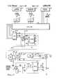
- FIG. 1is a schematic view of a laser surgical system for use in accordance with the invention
- FIG. 2is a side sectional view of the hand-piece of FIG. 1;
- FIG. 3is a block and schematic diagram of microprocessor control circuitry usable in the system of FIG. 1;
- FIGS. 4a-4care a flow diagram of a software program for use by the microprocessor of FIG. 3.
- Biological tissuecomprises cell layers in a protein framework for tensile strength. All proteins are amino acids which have side chains which are dissolvable either in water or fat.
- Naturationis a process wherein the amino acids fold over, always in the same configuration for each protein type, when the protein leaves the interior of a cell and is confronted with tissue water. In such case, the hydrophobic portion of a side chain folds to the interior of the molecule.
- the proteinaceous components of the tissuecan be unfolded or denatured by the application of heat.
- optical energycan be used to cause the body's own tissues to substantially reproduce the prior tissue structure at a wound or severed tissue site.
- energy from an optical energy sourcesuch as a laser, can be applied to bring the temperature of biological tissue somewhere above room temperature, but below the boiling point of water; preferably above 45 degrees centigrade and particularly to about 60-70 degrees centigrade.
- Collagena major source of protein in the body, is denatured by application of such energy in such a way as to go into solution and form a "biological glue" to seal a lesion, anastomize a severed vessel, or reconstruct damaged tissue.
- biological glueWhen the source of heat is removed, the proteins begin to re-nature and form an approximate replication of the prior tissue structure. As the body heals, the so-called “biological glue” will be reabsorbed and replaced by natural tissue.
- Optical energy of a particular wavelengthis converted to heat in tissue which absorbs energy at that wavelength.
- optical energy having a wavelength of 1.2 to 1.4 micrometersis relatively unattentuated in both water and blood and, so, is particularly advantageous for use as an optical energy source for the formation of a "biological glue" in order to effect repair of gastrointestinal tract tissue, close skin wounds (whether originating accidentally, intentionally or through biological processes), and repair and reconstruct tissue such as reproductive tissue, tendons, and vascular tissue, provided the intensity, exposure time and spot size of the beam at its point of incidence on the tissue are controlled to keep the energy absorption by the tissue within the desirable range.
- a suitable wavelengthis obtainable using a commercially available Nd:YAG laser configured to generate optical energy at a wavelength of about 1.32 micrometers.
- FIG. 1illustrates a surgical system for achieving tissue welding in accordance with the invention.
- the systemhas a source of optical energy, laser 20, which is preferably of the Nd:YAG crystalline variety wherein an yttrium-aluminum-garnet (YAG) rod is doped with neodymium (Nd) ions as the active light-producing element.
- a laser 20includes a resonant cavity for amplifying the emitted light and pumping means, such as a dc Krypton arc lamp, for supplying energy to create a population inversion of the normal energy state of Nd ions.
- the population inversionresults in the stimulated emission of light according to well-known known laser principles.
- Nd:YAG laserswill emit light at a fundamental dominant wavelength of 1.06 micrometers. Such lasers also emit light at a secondary wavelength of approximately 1.32 micrometers. Proper utilization of this secondary mode in laser operation requires the dominant emission, which has a greater amplitude than the secondary emission, to be suppressed. Typically, peak power output at this secondary emission level is 20-30% of the continuous wave peak power output at the dominant level. It is the secondary wavelength that is utilized in the method and apparatus of the invention.
- laser 20includes a power supply circuit for activating the pumping arc lamp and cooling means for cooling the laser.
- a suitable Nd:YAG laser for use in this inventionis produced by Control Laser Corporation, Orlando, Fla. 32809.
- a lens 21is provided to focus the emerging coherent light beam from laser 20 into an optical fiber 22.
- Lens 21may comprise a system of lenses.
- Optical fiber 22can be of any known type, which efficiently transmits the desired wavelength.
- Optical fiber 22provides a flexible conduit for guiding the optical energy from the laser into a hand-piece or wand 23 which is manipulable by the physician.
- a shutter 24is located, preferably, between laser 20 and lens 21.
- Hand-piece 23contains a shutter switch 25 which controls release of the laser energy and which may be actuated by either the hand or the foot of the operator.
- a timer 26is provided to control the shutter and, thereby, the duration of energy exposure.
- Hand-piece 23may include a lens (not shown) for focusing or defocusing the beam.
- hand-piece 23includes means to enable the physician to set the working distance between the tissue to be irradiated and the distalmost end of the optical fiber or lens.
- a sliding scale 27which cooperates with a protective case 28 on the end of optical fiber 22 controls the working distance, and hence, the diameter of the beam spot.
- the divergence of the beamis used to control the beam diameter as the distance between the distalmost end of the fiber 22 and the tissue is increased or decreased.
- the following electro-optical parametersrequire proper adjustment for each type of tissue: output power, time exposure and beam spot size.
- the thermal effects on the tissuecan be controlled by proper selection of the electro-optical parameters.
- Power densitymeasures the energy concentration of the applied light beam and is typically expressed in watts per square centimeter area of the applied beam spot. Power density is directly related to the amount of heat that will be produced at a given absorptivity. Radiant exposure, expressed in joules per square centimeter, is a measure of the power density multiplied by the exposure time. If the wavelength of the applied beam is poorly absorbed, more heat can be generated by increasing the time of tissue exposure to the applied beam. Laser output power and beam spot size selections affect the power density; overall radiant exposure is affected by power density and time exposure selections.
- Suitable means for control of the power output of laser 20is provided by a control unit 40, described further with reference to FIG. 3, below.
- Optical output power detector 41is provided for initial calibration of the beam of laser 20 at start-up and a second detector 42, which always receives a portion of the beam of laser 20 by means of a beam splitter 43, is provided for continuous monitoring and feedback adjustment of the laser 20 output.
- the power delivered to the tissue surfaceshould be maintained under 10 watts for purposes of tissue reconstruction by laser 20 as described herein.
- the objectis to deliver a specific amount of energy per volume of tissue. For a given spot size, which is related to the volume of tissue exposed, there are many combinations of power output and time exposure which will deliver equivalent amounts of energy. To-wit, power delivered to the tissue typically ranges between 1 and 4 watts; although power delivered could go as high as 10 watts if the time exposure were reduced commensurately.
- TEM ooIn the lowest order transmission mode, TEM oo specifically, a more concentrated beam results which can be used for cutting purposes at higher power output or for achieving very small beam spot size for tissue reconstruction.
- multimode transmissioncan be used for tissue reconstruction, but the beam spot size can not be as finely focused as the TEM oo mode. However, if the beam is defocused, less power is delivered per unit area.
- data relating to appropriate settings of electro-optical parameters for various tissue typescan be coded on a computer memory device, such as floppy disc or programmable read-only memory computer chip.
- the functions of control unit 40 and timer 26can be computer controlled to adjust automatically the power level, and time exposure and display the proper spot size upon input of tissue type and the operating conditions by the physician or surgeon.
- the system of FIG. 1also includes a marker laser 30, illustratively a low-power helium-neon laser, which is coaligned with the infrared beam of laser 20.
- Laser 30can be of any type which emits radiation in the visible range of the electromagnetic spectrum.
- the power rating of the helium-neon marker laser 30is between 1-5 Watts.
- Marker laser 30can be arranged so that its focal point coincides with that of the main operating laser 20 by any known technique.
- an auxiliary source of optical energy 50can be incorporated into the apparatus to emit radiation having a wavelength which is intensely absorbed by biological tissue.
- a carbon dioxide laserof any known type, would be a suitable auxiliary source.
- Source 50is also preferably arranged so as to have its output beam coincide with the beam from marker laser 30.
- FIG. 3shows suitable circuitry for implementation of the functions of the control unit 40 and timer 26 which utilizes a microprocessor 50, such as provided in an IBM PC/AT computer, for controlling parameters of the optical beam so as to deliver the appropriate amount of energy to the tissue reconstruction site.
- a microprocessor 50such as provided in an IBM PC/AT computer
- the computer 50accesses a data base stored in a memory device to establish appropriate settings for power level, time exposure and spot size.
- Optical output poweris controlled by delivery of a signal from the microprocessor to the conventional current control circuitry for the power supply of the laser 20.
- a digital-to-analog converter 62is connected to receive a digital current control signal from the microprocessor 50.
- the analog output of the converter 62is amplified by an amplifier 64 and then converted to a frequency signal by a voltage-to-frequency converter 65.
- the output of the converter 65is used via an isolating circuit 66 to drive a frequency-to-voltage converter 67 to deliver a signal from a power source 68 and voltage regulators 69, 70 through an amplifier 71 to the power control input of the laser 20 (e.g. the current control circuitry for a Control Laser Model 512 power supply).
- the isolation between the computer 50 and the laser 20is provided for protective purposes and may be achieved through use of an optocoupler.
- Verification of power setting accuracyis accomplished initially by requiring that the wand 23 end of the optical fiber 22 be inserted in the calibration port of power detector 41 located in a system console (not shown).
- the power detector 41may take the form of a coherent power detector, such as a thermal calorimeter. Following determination by the computer 50 of the correct power setting for the laser 20 for a particular tissue type and thickness, at first fire-up of the lamp the hand-piece or wand 23 is inserted in a receptacle on the control unit console. Initial firing of the laser is prevented unless the hand-piece 23 is in the receptacle.
- the output of the detector 41is amplified by an amplifier 72 and converted in an analog-to-digital converter 73 for input to the microprocessor 50.
- the microprocessor 50then performs a calibration subroutine to adjust the digital output to the converter 62 and thus to the laser power source, until the desired optical power output is read at the power detector 41.
- the value of the digital signal to converter 62is incremented; if the output is too high, it is decremented.
- the microprocessor 50will then clear the system for operation outside of the receptacle under control of the shutter switches 25 and timer 26.
- microprocessor 50Subsequent beam output adjustment is undertaken by microprocessor 50, in accordance with well-known principles, by which a small amount of the optical output is diverted by the beam splitter 43 (FIG. 1) for measurement by the detector 42, which suitably takes the form of a photodiode connected through an amplifier 74 and an analog-to-digital converter 75 to deliver a power level input to the microprocessor 50.
- the photodiode 42 circuitprovides a continuous feedback loop through the microprocessor 50 for power output vertification.
- a shutter switch 25(FIG. 1) is provided control to emission of the beam toward the tissue.
- the computer 50also serves the function of a timer 26 (FIG. 1) to limit the total time for which shutter 24 permits the beam from laser 20 to reach the tissue on any one shot.
- the shutter 24is arranged to normally be in a beam blocking position.
- the switch 25is connected to the computer 50 with the aid of an amplifier 76, as shown in FIG. 3, and programming is provided so that a counter is set up to increment for each clock pulse received during the time that shutter 24 is open. When the count indicates that the total specified exposure time set by computer 52 is reached the shutter will be closed and blocked from reopening until a certain counter reset time delay has passed.
- timer 26 shutter control circuitryThis ensures that each passage of beam energy from the laser 20 will have the required energy. It will be appreciated that other arrangements for the timer 26 shutter control circuitry are possible and that, in particular, the function by programming in microprocessor 50 can be replaced by hardwired timer circuitry, if desired.
- the diameter of the beam spot at the point of impact with the tissueis controlled by setting the working distance from the distalmost end of the fiber 22 to the tissue. As shown in FIG. 2, this is accomplished by manual manipulation of the sliding scale 27 to achieve the distance specified by the computer 50 to give the required beam diameter and beam energy denisty required for the subject tissue type and thickness. In response to input of the tissue characteristics, the computer displays the required setting. It will be appreciated that beam shaping may be accomplished in other ways and that the scale movement can be accomplished automatically, if desired. The shown means is, however, a simple workable approach that lends itself readily and inexpensively for use on a disposable optical fiber 22 for use in a sterile environment.
- tissue characteristicsFor input of tissue characteristics to the microprocessor 50 a conventional data input device, such as a keyboard is used. Known touch screen or voice activated input devices may also be used. It is preferable for the input process to be undertaken under prompting by tissue type and thickness selection menus appearing on a visual display.
- FIGS. 4A-4Cpresent an overall flow diagram of the software steps performed by the computer 50 for controlling the parameters of the beam in accordance with selected tissue characteristics
- the computer 52undergoes a series of checks.
- instructionsare given at 102 on a display device, such as a cathode ray tube screen, for insertion of nonwand end of the fiber into the laser console.
- the fiberIn order to engage the laser power supply, the fiber has to be in the inserted "power output" ready position. If the fiber is not in the correct position the power supply to the system will be disabled at 103, 104, preventing operation of the laser 20 until a correction is made at 105.
- the illustrated embodimentcontemplates the use of a key switch on the operating console, so the program awaits the positioning of that switch into the lamp on position before proceeding.
- the programUpon receipt at 107 of the awaited keyswitch signal, the program then proceeds to do some preliminary checks, such as checking the status of the laser cooling system at 108. For example, the deionized water is checked for proper conductivity, pressure and temperature. Other checks and diagnostics can also be run. Also, security subroutines can be implemented at this or another stage to ensure that only authorized individuals operate the beam itself. Should the diagnostics or other checks indicate some discrepancy at 109, the program will be directed to block further operation of the system, as at 104.
- the programinitiates a signal to fire the krypton lamp to activate the laser 20.
- a determinationis made, such as by looking at the signal from detector 42 (FIG. 3), at 111 to ensure that the lamp is on. If the lamp is not on, retriggering is initiated at 112. If after five attempts, the lamp does not light, a message is displayed at 114 to replace the lamp or repair the power supply.
- tissue characteristicsare entered into the computer 52.
- a suitable way to accomplish thatis to utilize a menu-driven tissue selection process. Available tissue selections are displayed on the screen, and input is solicited. Once tissue type is entered, the menu will be changed to solicit input as to tissue thickness.
- the computer 52addresses data stored in a memory device, such as a disk in a disk drive, and at 116 determines the laser operation parameters appropriate for the selected tissue characteristics.
- tissue type and thicknessit is advisable to provide some feedback to the user on tissue type and thickness to guard against input error. This can be done using any of several well known techniques.
- One wayis to display graphic representations of the selected tissue type and thickness on a display screen to provide an easily identifiable visual check to give reassurance to the user.
- the laser parameters obtained from lookup in the memory storage deviceinclude a combination of laser power (Pr), exposure time (Tr) and fiber tip position (Dr) settings that will deliver a controlled amount of optical energy to the selected tissue type and thickness to nondestructively convert it to a denatured proteinaceous collagenous substance to close join it together.
- Prlaser power
- Trexposure time
- Drfiber tip position
- the laser power and exposure time parametersare fed to assembly programs for direct control of the power and shutter control circuitry described perviously.
- instructions for manual setting of the fiber guide sliding scale 27 to establish the correct fiber tip position (Dr)are displayed on the screen at 117.
- Shutter switch 25 actuationis monitored at 122.
- the actual laser beam output reading (Pa) detected by the detector 41(FIG. 3) is compared with the computer 50 designated reference output Pr.
- the lamp current control hardwareis adjusted until the measured output power is the same as the computer specified output power.
- the switch 25is then closed at 126.
- the usercan now proceed to control the shutter 24 with the switch 25 at 128 in order to conduct the tissue joining process.
- the usercan elect at 129 to revise the parameters to those more suited to another tissue, whereupon the program will repeat the previous steps.
- Depressing the switch 25will open the shutter 24 for tissue welding at 130.
- the shutter open timewill be monitored as already described, with the shutter 24 closing when the timed actual exposure time Ta reaches the specified exposure time Tr, at 131.
- the footswitchis disabled at 132 and footswitch status (depressed or released) is determined at 133.
- the timeris reset and the program directed back to step 127 to ready the system for another shot.
- the programcan be modified and embellished to meet specific needs. It can be integrated with a program to display patient case history data and to update the patient file automatically to record the details of the procedure applied to that patient.
- the apparatus of FIG. 1is used for skin closure at a lesion site.
- the tissue edges of the lesionare brought into close approximation by manual manipulation, for example.
- Hand-piece 23is positioned above the lesion at such a distance as to produce the desired beam spot size.
- the power, time exposure and spot sizeare set so as to heat the tissue above 45 degrees centigrade, but below the boiling point of water (100 degrees centigrade).
- Typical spot sizesrange from 0.1 mm to 1.0 mm for levels of power delivered to the tissue ranging from 1 to 5 watts, and time durations ranging from 0.05 to 5.0 seconds.
- the tissue at the lesion siteis heated to a temperature sufficient to cause denaturization of the tissue proteins to the depth necessary to reconstruct the tissue in the lesion irrespective of whether the operating field is bloody or wet.
- the electro-optical parametersare set and controlled in response to input as to tissue type and thickness. Parameters may be specified for the reconstruction of many soft tissues such as vascular structures, tendon, vas deferens, fallopian tubes, gastrointestinal tract, dura, and sclera. With an appropriately controlled modification of the level of power delivered to the tissue under repair, cartilage and tympanic membranes can also be repaired in accordance with the invention described hereinabove.
- the laser energycan be transmitted to the patient treatment site by an articulated arm with mirrors or it can be transmitted to the interior of a patient by endoscope.
- materials other than neodymium-doped crystalline yttrium-aluminum-garnetcan be used as a lasing medium to generate optical energy at the desired wavelengths.
Landscapes
- Health & Medical Sciences (AREA)
- Surgery (AREA)
- Life Sciences & Earth Sciences (AREA)
- Physics & Mathematics (AREA)
- Engineering & Computer Science (AREA)
- General Health & Medical Sciences (AREA)
- Nuclear Medicine, Radiotherapy & Molecular Imaging (AREA)
- Veterinary Medicine (AREA)
- Public Health (AREA)
- Biomedical Technology (AREA)
- Heart & Thoracic Surgery (AREA)
- Medical Informatics (AREA)
- Molecular Biology (AREA)
- Animal Behavior & Ethology (AREA)
- Otolaryngology (AREA)
- Optics & Photonics (AREA)
- Electromagnetism (AREA)
- Laser Surgery Devices (AREA)
Abstract
Description
Claims (20)
Priority Applications (3)
| Application Number | Priority Date | Filing Date | Title |
|---|---|---|---|
| US07/062,861US4854320A (en) | 1983-10-06 | 1987-06-16 | Laser healing method and apparatus |
| US07/380,622US5002051A (en) | 1983-10-06 | 1989-07-14 | Method for closing tissue wounds using radiative energy beams |
| US07/934,167US5409479A (en) | 1983-10-06 | 1992-08-24 | Method for closing tissue wounds using radiative energy beams |
Applications Claiming Priority (2)
| Application Number | Priority Date | Filing Date | Title |
|---|---|---|---|
| US06/539,527US4672969A (en) | 1983-10-06 | 1983-10-06 | Laser healing method |
| US07/062,861US4854320A (en) | 1983-10-06 | 1987-06-16 | Laser healing method and apparatus |
Related Parent Applications (1)
| Application Number | Title | Priority Date | Filing Date |
|---|---|---|---|
| US06/539,527Continuation-In-PartUS4672969A (en) | 1983-10-06 | 1983-10-06 | Laser healing method |
Related Child Applications (1)
| Application Number | Title | Priority Date | Filing Date |
|---|---|---|---|
| US07/380,622DivisionUS5002051A (en) | 1983-10-06 | 1989-07-14 | Method for closing tissue wounds using radiative energy beams |
Publications (1)
| Publication Number | Publication Date |
|---|---|
| US4854320Atrue US4854320A (en) | 1989-08-08 |
Family
ID=26742789
Family Applications (1)
| Application Number | Title | Priority Date | Filing Date |
|---|---|---|---|
| US07/062,861Expired - LifetimeUS4854320A (en) | 1983-10-06 | 1987-06-16 | Laser healing method and apparatus |
Country Status (1)
| Country | Link |
|---|---|
| US (1) | US4854320A (en) |
Cited By (104)
| Publication number | Priority date | Publication date | Assignee | Title |
|---|---|---|---|---|
| US5071417A (en)* | 1990-06-15 | 1991-12-10 | Rare Earth Medical Lasers, Inc. | Laser fusion of biological materials |
| US5092841A (en)* | 1990-05-17 | 1992-03-03 | Wayne State University | Method for treating an arterial wall injured during angioplasty |
| US5122659A (en)* | 1989-09-07 | 1992-06-16 | Fuji Photo Film Co., Ltd. | Radiation image read-out apparatus having a beam number reducing device |
| US5140984A (en)* | 1983-10-06 | 1992-08-25 | Proclosure, Inc. | Laser healing method and apparatus |
| WO1992014513A1 (en)* | 1991-02-13 | 1992-09-03 | Interface Biomedical Laboratories Corp. | Filler material for use in tissue welding |
| US5156613A (en)* | 1991-02-13 | 1992-10-20 | Interface Biomedical Laboratories Corp. | Collagen welding rod material for use in tissue welding |
| US5209776A (en)* | 1990-07-27 | 1993-05-11 | The Trustees Of Columbia University In The City Of New York | Tissue bonding and sealing composition and method of using the same |
| US5217455A (en)* | 1991-08-12 | 1993-06-08 | Tan Oon T | Laser treatment method for removing pigmentations, lesions, and abnormalities from the skin of a living human |
| US5292362A (en)* | 1990-07-27 | 1994-03-08 | The Trustees Of Columbia University In The City Of New York | Tissue bonding and sealing composition and method of using the same |
| US5300065A (en)* | 1992-11-06 | 1994-04-05 | Proclosure Inc. | Method and apparatus for simultaneously holding and sealing tissue |
| US5330974A (en)* | 1993-03-01 | 1994-07-19 | Fibratek, Inc. | Therapeutic fibrinogen compositions |
| US5334191A (en)* | 1992-05-21 | 1994-08-02 | Dix Phillip Poppas | Laser tissue welding control system |
| US5354323A (en)* | 1992-10-20 | 1994-10-11 | Premier Laser Systems, Inc. | Optical heating system |
| US5372585A (en)* | 1992-04-09 | 1994-12-13 | Tiefenbrun; Jonathan | Instrument and associated method for applying biologically effective composition during laparoscopic operation |
| WO1994028972A1 (en)* | 1993-05-14 | 1994-12-22 | Eberhard Oppold | Safety laser beam apertures (sla) for therapeutic and diagnostic medical equipment |
| US5403306A (en)* | 1993-06-22 | 1995-04-04 | Vanderbilt University | Laser surgery method |
| US5409479A (en)* | 1983-10-06 | 1995-04-25 | Premier Laser Systems, Inc. | Method for closing tissue wounds using radiative energy beams |
| US5445146A (en)* | 1995-03-31 | 1995-08-29 | Bellinger; Gary J. | Biological tissue stimulation by low level optical energy |
| US5454807A (en)* | 1993-05-14 | 1995-10-03 | Boston Scientific Corporation | Medical treatment of deeply seated tissue using optical radiation |
| US5495089A (en)* | 1993-06-04 | 1996-02-27 | Digital Equipment Corporation | Laser soldering surface mount components of a printed circuit board |
| WO1996007356A1 (en)* | 1994-09-06 | 1996-03-14 | Fusion Medical Technologies, Inc. | Methods and articles for staple line reinforcement |
| WO1996007355A1 (en)* | 1994-09-06 | 1996-03-14 | Fusion Medical Technologies, Inc. | Structure and method for bonding or fusion of biological materials |
| US5507744A (en)* | 1992-04-23 | 1996-04-16 | Scimed Life Systems, Inc. | Apparatus and method for sealing vascular punctures |
| US5540677A (en)* | 1990-06-15 | 1996-07-30 | Rare Earth Medical, Inc. | Endoscopic systems for photoreactive suturing of biological materials |
| US5552452A (en)* | 1993-03-15 | 1996-09-03 | Arch Development Corp. | Organic tissue glue for closure of wounds |
| US5571216A (en)* | 1994-01-19 | 1996-11-05 | The General Hospital Corporation | Methods and apparatus for joining collagen-containing materials |
| US5591157A (en)* | 1994-09-07 | 1997-01-07 | Hennings; David R. | Method and apparatus for tympanic membrane shrinkage |
| US5611794A (en)* | 1990-10-11 | 1997-03-18 | Lasersurge, Inc. | Clamp for approximating tissue sections |
| US5634936A (en)* | 1995-02-06 | 1997-06-03 | Scimed Life Systems, Inc. | Device for closing a septal defect |
| US5653706A (en)* | 1993-07-21 | 1997-08-05 | Lucid Technologies Inc. | Dermatological laser treatment system with electronic visualization of the area being treated |
| US5658323A (en)* | 1995-07-12 | 1997-08-19 | Miller; Iain D. | Method and apparatus for dermatology treatment |
| US5669934A (en)* | 1991-02-13 | 1997-09-23 | Fusion Medical Technologies, Inc. | Methods for joining tissue by applying radiofrequency energy to performed collagen films and sheets |
| US5674231A (en)* | 1995-10-20 | 1997-10-07 | United States Surgical Corporation | Apparatus and method for vascular hole closure |
| WO1997037723A1 (en)* | 1996-04-10 | 1997-10-16 | New Star Lasers, Inc. | Improved method and device for laser induced shrinking of collagen |
| US5713891A (en)* | 1995-06-02 | 1998-02-03 | Children's Medical Center Corporation | Modified solder for delivery of bioactive substances and methods of use thereof |
| US5725522A (en)* | 1990-06-15 | 1998-03-10 | Rare Earth Medical, Inc. | Laser suturing of biological materials |
| US5762609A (en)* | 1992-09-14 | 1998-06-09 | Sextant Medical Corporation | Device and method for analysis of surgical tissue interventions |
| US5769791A (en)* | 1992-09-14 | 1998-06-23 | Sextant Medical Corporation | Tissue interrogating device and methods |
| US5791352A (en)* | 1996-06-19 | 1998-08-11 | Fusion Medical Technologies, Inc. | Methods and compositions for inhibiting tissue adhesion |
| WO1998038933A1 (en)* | 1997-03-07 | 1998-09-11 | New Star Lasers, Inc. | Methods of modulating collagen biosynthesis by use of non-laser light |
| US5810801A (en)* | 1997-02-05 | 1998-09-22 | Candela Corporation | Method and apparatus for treating wrinkles in skin using radiation |
| US5810846A (en)* | 1995-08-03 | 1998-09-22 | United States Surgical Corporation | Vascular hole closure |
| US5810810A (en)* | 1992-04-23 | 1998-09-22 | Scimed Life Systems, Inc. | Apparatus and method for sealing vascular punctures |
| US5868731A (en)* | 1996-03-04 | 1999-02-09 | Innotech Usa, Inc. | Laser surgical device and method of its use |
| US5879376A (en)* | 1995-07-12 | 1999-03-09 | Luxar Corporation | Method and apparatus for dermatology treatment |
| US5895412A (en)* | 1995-10-11 | 1999-04-20 | Fusion Medical Technologies, Inc. | Device and method for sealing tissue |
| US5931165A (en)* | 1994-09-06 | 1999-08-03 | Fusion Medical Technologies, Inc. | Films having improved characteristics and methods for their preparation and use |
| US5951596A (en)* | 1991-07-01 | 1999-09-14 | Laser Biotherapy Inc | Biological tissue stimulation by optical energy |
| US6063085A (en)* | 1992-04-23 | 2000-05-16 | Scimed Life Systems, Inc. | Apparatus and method for sealing vascular punctures |
| US6071303A (en)* | 1996-12-08 | 2000-06-06 | Hearten Medical, Inc. | Device for the treatment of infarcted tissue and method of treating infarcted tissue |
| US6211335B1 (en) | 1995-01-20 | 2001-04-03 | The Microsearch Foundation Of Australia | Method of tissue repair |
| US6267779B1 (en) | 1999-03-29 | 2001-07-31 | Medelaser, Llc | Method and apparatus for therapeutic laser treatment |
| US6391049B1 (en) | 1999-10-06 | 2002-05-21 | Board Of Regents The University Of Texas System | Solid biodegradable device for use in tissue repair |
| US6428532B1 (en)* | 1998-12-30 | 2002-08-06 | The General Hospital Corporation | Selective tissue targeting by difference frequency of two wavelengths |
| US20030155336A1 (en)* | 2000-02-15 | 2003-08-21 | Kreuter R?Uuml;Diger | Method for the machining of workpieces by means of several laser beams |
| US20030191511A1 (en)* | 1999-04-16 | 2003-10-09 | Tony R. Brown | Device for shaping infarcted heart tissue and method of using the device |
| US6676654B1 (en) | 1997-08-29 | 2004-01-13 | Asah Medico A/S | Apparatus for tissue treatment and having a monitor for display of tissue features |
| US6685730B2 (en) | 2001-09-26 | 2004-02-03 | Rice University | Optically-absorbing nanoparticles for enhanced tissue repair |
| US20040034340A1 (en)* | 1999-10-13 | 2004-02-19 | Spineco, Inc., An Ohio Corporation | Smart dissector |
| US20040133191A1 (en)* | 2002-12-27 | 2004-07-08 | Masayuki Momiuchi | Laser device for medical treatment system |
| US20050015123A1 (en)* | 2003-06-30 | 2005-01-20 | Paithankar Dilip Y. | Endovascular treatment of a blood vessel using a light source |
| US20050027336A1 (en)* | 2003-03-03 | 2005-02-03 | Mikhail Nemenov | Portable laser and process for producing controlled pain |
| US6858114B2 (en) | 2001-07-03 | 2005-02-22 | The University Of Alabama | Laser hydrolysis of polypeptides |
| WO2004039435A3 (en)* | 2002-10-31 | 2005-04-28 | Cooltouch Inc | Endovenous closure of varicose veins with mid infrared laser |
| US20050131400A1 (en)* | 2002-10-31 | 2005-06-16 | Cooltouch, Inc. | Endovenous closure of varicose veins with mid infrared laser |
| US20070123846A1 (en)* | 2002-10-31 | 2007-05-31 | Cooltouch Incorporated | Preparation for endovenous laser ablation |
| US20070156210A1 (en)* | 2005-01-14 | 2007-07-05 | Co-Repair, Inc., A California Corporation | Method for the treatment of heart tissue |
| US20070173913A1 (en)* | 2003-04-15 | 2007-07-26 | The General Hospital Corporation D/B/A Massachusetts General Hospital | Methods and devices for epithelial protection during photodynamic therapy |
| US20080021527A1 (en)* | 2003-10-30 | 2008-01-24 | Cooltouch Incorporated | Endovenous laser treatment generating reduced blood coagulation |
| WO2008053491A3 (en)* | 2006-11-01 | 2008-06-19 | Seraffix Ltd | System and method for tissue soldering |
| US20080172105A1 (en)* | 2007-01-17 | 2008-07-17 | Ws Far Ir Medical Technology Co., Ltd. | Method for preventing and/or ameliorating inflammation |
| US20080188835A1 (en)* | 2005-05-18 | 2008-08-07 | Cooltouch Incorporated | Treatment of cellulite and adipose tissue with mid-infrared radiation |
| WO2008131558A1 (en)* | 2007-05-01 | 2008-11-06 | Urodynamix Technologies Ltd. | Light-emitting medical devices having protections against unintended light exposure |
| US20080306476A1 (en)* | 2005-05-18 | 2008-12-11 | Cooltouch Incorporated | Thermally mediated tissue molding |
| US20090137998A1 (en)* | 1997-09-11 | 2009-05-28 | Zikorus Arthur W | Expandable vein ligator catheter having multiple electrode leads, and method |
| USRE40863E1 (en)* | 1992-04-23 | 2009-07-21 | Boston Scientific Scimed, Inc. | Apparatus and method for sealing vascular punctures |
| WO2009111010A1 (en)* | 2008-03-03 | 2009-09-11 | Seminex Corp. | Portable semiconductor diode laser for medical treatment |
| US20090234228A1 (en)* | 2008-03-17 | 2009-09-17 | Or-Nim Medical Ltd. | Apparatus for non-invasive optical monitoring |
| US20090287204A1 (en)* | 2005-01-14 | 2009-11-19 | Co-Repair, Inc. | System And Method For The Treatment Of Heart Tissue |
| US20100174223A1 (en)* | 2007-06-27 | 2010-07-08 | The General Hospital Corporation D/B/A Massachusetts General Hospital | Method and apparatus for optical inhibition of photodynamic therapy |
| US20100249763A1 (en)* | 2007-05-14 | 2010-09-30 | The Regents Of The University Of Colorado | Laser Tissue Fusion of Septal Membranes |
| US20100280545A1 (en)* | 2007-05-10 | 2010-11-04 | Seraffix Ltd. | System and method for bonding living tissue |
| US7891362B2 (en) | 2005-12-23 | 2011-02-22 | Candela Corporation | Methods for treating pigmentary and vascular abnormalities in a dermal region |
| US20110172746A1 (en)* | 2010-01-12 | 2011-07-14 | Roger Porter | High Level Laser Therapy Apparatus and Methods |
| US8033284B2 (en) | 2006-01-11 | 2011-10-11 | Curaelase, Inc. | Therapeutic laser treatment |
| US20110270071A1 (en)* | 2010-04-28 | 2011-11-03 | Canon Kabushiki Kaisha | Measuring apparatus |
| US8246611B2 (en) | 2006-06-14 | 2012-08-21 | Candela Corporation | Treatment of skin by spatial modulation of thermal heating |
| US8277495B2 (en) | 2005-01-13 | 2012-10-02 | Candela Corporation | Method and apparatus for treating a diseased nail |
| US8285393B2 (en) | 1999-04-16 | 2012-10-09 | Laufer Michael D | Device for shaping infarcted heart tissue and method of using the device |
| ITBG20110018A1 (en)* | 2011-05-26 | 2012-11-27 | Bergamasca Di Servizi Medi Ci E Informati Soc | SYSTEM FOR THE MANAGEMENT OF A LASER THERAPY MACHINE |
| US8366706B2 (en) | 2007-08-15 | 2013-02-05 | Cardiodex, Ltd. | Systems and methods for puncture closure |
| US8372072B2 (en) | 2003-02-04 | 2013-02-12 | Cardiodex Ltd. | Methods and apparatus for hemostasis following arterial catheterization |
| US8409183B2 (en) | 2003-10-30 | 2013-04-02 | Cooltouch Incorporated | Endovenous laser treatment generating reduced blood coagulation |
| US20130085461A1 (en)* | 2011-10-04 | 2013-04-04 | Dermal Therapy (Barbados) Inc. | Method for Pre-Debriding Treatment of Non-Viable Skin Tissue and Compositions and System Thereof |
| US8435236B2 (en) | 2004-11-22 | 2013-05-07 | Cardiodex, Ltd. | Techniques for heat-treating varicose veins |
| US20130178921A1 (en)* | 2007-03-15 | 2013-07-11 | Charles Brian Rogers | System and apparatus providing a controlled light source for medicinal applications |
| US9028469B2 (en) | 2005-09-28 | 2015-05-12 | Candela Corporation | Method of treating cellulite |
| US9113900B2 (en) | 1998-10-23 | 2015-08-25 | Covidien Ag | Method and system for controlling output of RF medical generator |
| US9113933B2 (en) | 2011-05-16 | 2015-08-25 | Covidien Lp | Optical energy-based methods and apparatus for tissue sealing |
| US9113934B2 (en) | 2011-05-16 | 2015-08-25 | Covidien Lp | Optical energy-based methods and apparatus for tissue sealing |
| US9456870B2 (en) | 2011-05-16 | 2016-10-04 | Covidien Lp | Optical energy-based methods and apparatus for tissue sealing |
| US9833285B2 (en) | 2012-07-17 | 2017-12-05 | Covidien Lp | Optical sealing device with cutting ability |
| US9907975B1 (en) | 2014-11-19 | 2018-03-06 | Roger D. Porter | Therapeutic laser treatment and transdermal stimulation of stem cell differentiation |
| US11007373B1 (en) | 2002-12-20 | 2021-05-18 | James Andrew Ohneck | Photobiostimulation device and method of using same |
Citations (14)
| Publication number | Priority date | Publication date | Assignee | Title |
|---|---|---|---|---|
| US3467098A (en)* | 1967-03-24 | 1969-09-16 | Becton Dickinson Co | Flexible conduit for laser surgery |
| US3750670A (en)* | 1970-08-03 | 1973-08-07 | Medoptics Inc | Laser cauterizer |
| US3769963A (en)* | 1972-03-31 | 1973-11-06 | L Goldman | Instrument for performing laser micro-surgery and diagnostic transillumination of living human tissue |
| US3794040A (en)* | 1967-10-27 | 1974-02-26 | Ultrasonic Systems | Ultrasonic surgical procedures |
| US3865113A (en)* | 1972-10-17 | 1975-02-11 | Laser Ind Ltd | Laser device particularly useful as surgical scalpel |
| SU618116A1 (en)* | 1975-01-24 | 1978-08-05 | Предприятие П/Я Г-4147 | Method of connecting the tissues of hollow organs |
| US4122853A (en)* | 1977-03-14 | 1978-10-31 | Spectra-Med | Infrared laser photocautery device |
| DE2809007A1 (en)* | 1978-03-02 | 1979-09-13 | Messerschmitt Boelkow Blohm | Live tissue cutting and coagulating instrument - has two different wavelength laser beams and pilot light(s) passed together through manipulator to emerge coaxially from it |
| US4266549A (en)* | 1978-10-12 | 1981-05-12 | Hiroaki Kimura | Laser scalpel |
| SU886907A1 (en)* | 1980-01-04 | 1981-12-07 | Московский Городской Ордена Ленина И Ордена Трудового Красного Знамени Научно-Исследовательский Институт Скорой Помощи Им.Н.В.Склифосовского | Method of treating burns |
| FR2494986A1 (en)* | 1980-11-04 | 1982-06-04 | Agency Ind Science Techn | LASER BISTOURI |
| EP0075860A2 (en)* | 1981-09-24 | 1983-04-06 | James Robert Morris | Microsurgical laser |
| DE3242612A1 (en)* | 1981-11-19 | 1983-05-26 | Nippon Infrared Industries Co., Ltd., Tokyo | LASER BEAM DEVICE |
| US4520816A (en)* | 1983-01-12 | 1985-06-04 | Schachar Ronald A | Method and apparatus for delivering laser energy for ophthalmic use |
- 1987
- 1987-06-16USUS07/062,861patent/US4854320A/ennot_activeExpired - Lifetime
Patent Citations (16)
| Publication number | Priority date | Publication date | Assignee | Title |
|---|---|---|---|---|
| US3467098A (en)* | 1967-03-24 | 1969-09-16 | Becton Dickinson Co | Flexible conduit for laser surgery |
| US3794040A (en)* | 1967-10-27 | 1974-02-26 | Ultrasonic Systems | Ultrasonic surgical procedures |
| US3750670A (en)* | 1970-08-03 | 1973-08-07 | Medoptics Inc | Laser cauterizer |
| US3769963A (en)* | 1972-03-31 | 1973-11-06 | L Goldman | Instrument for performing laser micro-surgery and diagnostic transillumination of living human tissue |
| US3865113A (en)* | 1972-10-17 | 1975-02-11 | Laser Ind Ltd | Laser device particularly useful as surgical scalpel |
| SU618116A1 (en)* | 1975-01-24 | 1978-08-05 | Предприятие П/Я Г-4147 | Method of connecting the tissues of hollow organs |
| US4122853A (en)* | 1977-03-14 | 1978-10-31 | Spectra-Med | Infrared laser photocautery device |
| DE2809007A1 (en)* | 1978-03-02 | 1979-09-13 | Messerschmitt Boelkow Blohm | Live tissue cutting and coagulating instrument - has two different wavelength laser beams and pilot light(s) passed together through manipulator to emerge coaxially from it |
| US4266549A (en)* | 1978-10-12 | 1981-05-12 | Hiroaki Kimura | Laser scalpel |
| SU886907A1 (en)* | 1980-01-04 | 1981-12-07 | Московский Городской Ордена Ленина И Ордена Трудового Красного Знамени Научно-Исследовательский Институт Скорой Помощи Им.Н.В.Склифосовского | Method of treating burns |
| FR2494986A1 (en)* | 1980-11-04 | 1982-06-04 | Agency Ind Science Techn | LASER BISTOURI |
| US4470414A (en)* | 1980-11-04 | 1984-09-11 | Agency Of Industrial Science & Technology | Laser surgical knife |
| EP0075860A2 (en)* | 1981-09-24 | 1983-04-06 | James Robert Morris | Microsurgical laser |
| DE3242612A1 (en)* | 1981-11-19 | 1983-05-26 | Nippon Infrared Industries Co., Ltd., Tokyo | LASER BEAM DEVICE |
| US4573465A (en)* | 1981-11-19 | 1986-03-04 | Nippon Infrared Industries Co., Ltd. | Laser irradiation apparatus |
| US4520816A (en)* | 1983-01-12 | 1985-06-04 | Schachar Ronald A | Method and apparatus for delivering laser energy for ophthalmic use |
Non-Patent Citations (4)
| Title |
|---|
| Jain, Surgery, vol. 85, No. 6, Jun., 1979, "Repair of Small Blood Vessels with the Neodymium-YAG Laser: A Preliminary Report", pp. 684-687. |
| Jain, Surgery, vol. 85, No. 6, Jun., 1979, Repair of Small Blood Vessels with the Neodymium YAG Laser: A Preliminary Report , pp. 684 687.* |
| Jain, The Lancet, Oct. 6, 1984, "Sutureless Extra-Intracranial Anastomosis By Laser", pp. 816-817. |
| Jain, The Lancet, Oct. 6, 1984, Sutureless Extra Intracranial Anastomosis By Laser , pp. 816 817.* |
Cited By (144)
| Publication number | Priority date | Publication date | Assignee | Title |
|---|---|---|---|---|
| US5409479A (en)* | 1983-10-06 | 1995-04-25 | Premier Laser Systems, Inc. | Method for closing tissue wounds using radiative energy beams |
| US5140984A (en)* | 1983-10-06 | 1992-08-25 | Proclosure, Inc. | Laser healing method and apparatus |
| US5122659A (en)* | 1989-09-07 | 1992-06-16 | Fuji Photo Film Co., Ltd. | Radiation image read-out apparatus having a beam number reducing device |
| US5092841A (en)* | 1990-05-17 | 1992-03-03 | Wayne State University | Method for treating an arterial wall injured during angioplasty |
| US5725522A (en)* | 1990-06-15 | 1998-03-10 | Rare Earth Medical, Inc. | Laser suturing of biological materials |
| US5540677A (en)* | 1990-06-15 | 1996-07-30 | Rare Earth Medical, Inc. | Endoscopic systems for photoreactive suturing of biological materials |
| US5071417A (en)* | 1990-06-15 | 1991-12-10 | Rare Earth Medical Lasers, Inc. | Laser fusion of biological materials |
| US5292362A (en)* | 1990-07-27 | 1994-03-08 | The Trustees Of Columbia University In The City Of New York | Tissue bonding and sealing composition and method of using the same |
| US5209776A (en)* | 1990-07-27 | 1993-05-11 | The Trustees Of Columbia University In The City Of New York | Tissue bonding and sealing composition and method of using the same |
| US5611794A (en)* | 1990-10-11 | 1997-03-18 | Lasersurge, Inc. | Clamp for approximating tissue sections |
| US5690675A (en)* | 1991-02-13 | 1997-11-25 | Fusion Medical Technologies, Inc. | Methods for sealing of staples and other fasteners in tissue |
| WO1992014513A1 (en)* | 1991-02-13 | 1992-09-03 | Interface Biomedical Laboratories Corp. | Filler material for use in tissue welding |
| US5749895A (en)* | 1991-02-13 | 1998-05-12 | Fusion Medical Technologies, Inc. | Method for bonding or fusion of biological tissue and material |
| US5156613A (en)* | 1991-02-13 | 1992-10-20 | Interface Biomedical Laboratories Corp. | Collagen welding rod material for use in tissue welding |
| US5669934A (en)* | 1991-02-13 | 1997-09-23 | Fusion Medical Technologies, Inc. | Methods for joining tissue by applying radiofrequency energy to performed collagen films and sheets |
| US5824015A (en)* | 1991-02-13 | 1998-10-20 | Fusion Medical Technologies, Inc. | Method for welding biological tissue |
| US5951596A (en)* | 1991-07-01 | 1999-09-14 | Laser Biotherapy Inc | Biological tissue stimulation by optical energy |
| US5290273A (en)* | 1991-08-12 | 1994-03-01 | Tan Oon T | Laser treatment method for removing pigement containing lesions from the skin of a living human |
| US5217455A (en)* | 1991-08-12 | 1993-06-08 | Tan Oon T | Laser treatment method for removing pigmentations, lesions, and abnormalities from the skin of a living human |
| US5372585A (en)* | 1992-04-09 | 1994-12-13 | Tiefenbrun; Jonathan | Instrument and associated method for applying biologically effective composition during laparoscopic operation |
| USRE40863E1 (en)* | 1992-04-23 | 2009-07-21 | Boston Scientific Scimed, Inc. | Apparatus and method for sealing vascular punctures |
| US5810810A (en)* | 1992-04-23 | 1998-09-22 | Scimed Life Systems, Inc. | Apparatus and method for sealing vascular punctures |
| US6063085A (en)* | 1992-04-23 | 2000-05-16 | Scimed Life Systems, Inc. | Apparatus and method for sealing vascular punctures |
| US5507744A (en)* | 1992-04-23 | 1996-04-16 | Scimed Life Systems, Inc. | Apparatus and method for sealing vascular punctures |
| US5409481A (en)* | 1992-05-21 | 1995-04-25 | Laserscope | Laser tissue welding control system |
| US5334191A (en)* | 1992-05-21 | 1994-08-02 | Dix Phillip Poppas | Laser tissue welding control system |
| US5807261A (en)* | 1992-09-14 | 1998-09-15 | Sextant Medical Corporation | Noninvasive system for characterizing tissue in vivo |
| US5772597A (en)* | 1992-09-14 | 1998-06-30 | Sextant Medical Corporation | Surgical tool end effector |
| US5769791A (en)* | 1992-09-14 | 1998-06-23 | Sextant Medical Corporation | Tissue interrogating device and methods |
| US5762609A (en)* | 1992-09-14 | 1998-06-09 | Sextant Medical Corporation | Device and method for analysis of surgical tissue interventions |
| US5354323A (en)* | 1992-10-20 | 1994-10-11 | Premier Laser Systems, Inc. | Optical heating system |
| US5300065A (en)* | 1992-11-06 | 1994-04-05 | Proclosure Inc. | Method and apparatus for simultaneously holding and sealing tissue |
| US20050136046A1 (en)* | 1993-03-01 | 2005-06-23 | Eli Pines | Methods of using therapeutic fibrinogen compositions |
| US5605887A (en)* | 1993-03-01 | 1997-02-25 | Fibratek, Inc. | Therapeutic fibrinogen compositions |
| US5330974A (en)* | 1993-03-01 | 1994-07-19 | Fibratek, Inc. | Therapeutic fibrinogen compositions |
| US5552452A (en)* | 1993-03-15 | 1996-09-03 | Arch Development Corp. | Organic tissue glue for closure of wounds |
| US5454807A (en)* | 1993-05-14 | 1995-10-03 | Boston Scientific Corporation | Medical treatment of deeply seated tissue using optical radiation |
| WO1994028972A1 (en)* | 1993-05-14 | 1994-12-22 | Eberhard Oppold | Safety laser beam apertures (sla) for therapeutic and diagnostic medical equipment |
| US5495089A (en)* | 1993-06-04 | 1996-02-27 | Digital Equipment Corporation | Laser soldering surface mount components of a printed circuit board |
| US5403306A (en)* | 1993-06-22 | 1995-04-04 | Vanderbilt University | Laser surgery method |
| US5653706A (en)* | 1993-07-21 | 1997-08-05 | Lucid Technologies Inc. | Dermatological laser treatment system with electronic visualization of the area being treated |
| US5571216A (en)* | 1994-01-19 | 1996-11-05 | The General Hospital Corporation | Methods and apparatus for joining collagen-containing materials |
| US5925078A (en)* | 1994-01-19 | 1999-07-20 | The General Hospital Corporation | Methods and apparatus for joining collagen-containing materials |
| WO1996007355A1 (en)* | 1994-09-06 | 1996-03-14 | Fusion Medical Technologies, Inc. | Structure and method for bonding or fusion of biological materials |
| US5931165A (en)* | 1994-09-06 | 1999-08-03 | Fusion Medical Technologies, Inc. | Films having improved characteristics and methods for their preparation and use |
| WO1996007356A1 (en)* | 1994-09-06 | 1996-03-14 | Fusion Medical Technologies, Inc. | Methods and articles for staple line reinforcement |
| US5591157A (en)* | 1994-09-07 | 1997-01-07 | Hennings; David R. | Method and apparatus for tympanic membrane shrinkage |
| US6583117B2 (en) | 1995-01-20 | 2003-06-24 | The Microsearch Foundation Of Australia | Method of tissue repair |
| US6211335B1 (en) | 1995-01-20 | 2001-04-03 | The Microsearch Foundation Of Australia | Method of tissue repair |
| US20050079997A1 (en)* | 1995-01-20 | 2005-04-14 | Owen Earl Ronald | Method of tissue repair |
| US6270515B1 (en) | 1995-02-06 | 2001-08-07 | Scimed Life Systems, Inc. | Device for closing a septal defect |
| US5634936A (en)* | 1995-02-06 | 1997-06-03 | Scimed Life Systems, Inc. | Device for closing a septal defect |
| WO1996030083A1 (en)* | 1995-03-31 | 1996-10-03 | Bellinger Gary J | Biological tissue stimulation by optical energy |
| US5445146A (en)* | 1995-03-31 | 1995-08-29 | Bellinger; Gary J. | Biological tissue stimulation by low level optical energy |
| US5713891A (en)* | 1995-06-02 | 1998-02-03 | Children's Medical Center Corporation | Modified solder for delivery of bioactive substances and methods of use thereof |
| US6027495A (en)* | 1995-07-12 | 2000-02-22 | Esc Medical Systems Ltd. | Method and apparatus for dermatology treatment |
| US5879376A (en)* | 1995-07-12 | 1999-03-09 | Luxar Corporation | Method and apparatus for dermatology treatment |
| US5658323A (en)* | 1995-07-12 | 1997-08-19 | Miller; Iain D. | Method and apparatus for dermatology treatment |
| US5810846A (en)* | 1995-08-03 | 1998-09-22 | United States Surgical Corporation | Vascular hole closure |
| US5895412A (en)* | 1995-10-11 | 1999-04-20 | Fusion Medical Technologies, Inc. | Device and method for sealing tissue |
| US5674231A (en)* | 1995-10-20 | 1997-10-07 | United States Surgical Corporation | Apparatus and method for vascular hole closure |
| US5868731A (en)* | 1996-03-04 | 1999-02-09 | Innotech Usa, Inc. | Laser surgical device and method of its use |
| WO1997037723A1 (en)* | 1996-04-10 | 1997-10-16 | New Star Lasers, Inc. | Improved method and device for laser induced shrinking of collagen |
| US5791352A (en)* | 1996-06-19 | 1998-08-11 | Fusion Medical Technologies, Inc. | Methods and compositions for inhibiting tissue adhesion |
| US6071303A (en)* | 1996-12-08 | 2000-06-06 | Hearten Medical, Inc. | Device for the treatment of infarcted tissue and method of treating infarcted tissue |
| US6120497A (en)* | 1997-02-05 | 2000-09-19 | Massachusetts General Hospital | Method and apparatus for treating wrinkles in skin using radiation |
| US5810801A (en)* | 1997-02-05 | 1998-09-22 | Candela Corporation | Method and apparatus for treating wrinkles in skin using radiation |
| US6659999B1 (en) | 1997-02-05 | 2003-12-09 | Candela Corporation | Method and apparatus for treating wrinkles in skin using radiation |
| WO1998038933A1 (en)* | 1997-03-07 | 1998-09-11 | New Star Lasers, Inc. | Methods of modulating collagen biosynthesis by use of non-laser light |
| US6676654B1 (en) | 1997-08-29 | 2004-01-13 | Asah Medico A/S | Apparatus for tissue treatment and having a monitor for display of tissue features |
| USRE38670E1 (en) | 1997-08-29 | 2004-12-14 | Asah Medico A/S | Apparatus for tissue treatment |
| US8679110B2 (en) | 1997-09-11 | 2014-03-25 | Covidien Lp | Expandable vein ligator catheter having multiple electrode leads, and method |
| US20090137998A1 (en)* | 1997-09-11 | 2009-05-28 | Zikorus Arthur W | Expandable vein ligator catheter having multiple electrode leads, and method |
| US9113900B2 (en) | 1998-10-23 | 2015-08-25 | Covidien Ag | Method and system for controlling output of RF medical generator |
| US9168089B2 (en) | 1998-10-23 | 2015-10-27 | Covidien Ag | Method and system for controlling output of RF medical generator |
| US6428532B1 (en)* | 1998-12-30 | 2002-08-06 | The General Hospital Corporation | Selective tissue targeting by difference frequency of two wavelengths |
| US6267779B1 (en) | 1999-03-29 | 2001-07-31 | Medelaser, Llc | Method and apparatus for therapeutic laser treatment |
| US20030191511A1 (en)* | 1999-04-16 | 2003-10-09 | Tony R. Brown | Device for shaping infarcted heart tissue and method of using the device |
| US8285393B2 (en) | 1999-04-16 | 2012-10-09 | Laufer Michael D | Device for shaping infarcted heart tissue and method of using the device |
| US7039469B2 (en) | 1999-04-16 | 2006-05-02 | Michael D. Laufer | Device for shaping infarcted heart tissue and method of using the device |
| US6391049B1 (en) | 1999-10-06 | 2002-05-21 | Board Of Regents The University Of Texas System | Solid biodegradable device for use in tissue repair |
| US20040034340A1 (en)* | 1999-10-13 | 2004-02-19 | Spineco, Inc., An Ohio Corporation | Smart dissector |
| US6838639B2 (en)* | 2000-02-15 | 2005-01-04 | Datacard Corporation | Method for the machining of workpieces by means of several laser beams |
| US20030155336A1 (en)* | 2000-02-15 | 2003-08-21 | Kreuter R?Uuml;Diger | Method for the machining of workpieces by means of several laser beams |
| US6858114B2 (en) | 2001-07-03 | 2005-02-22 | The University Of Alabama | Laser hydrolysis of polypeptides |
| US6685730B2 (en) | 2001-09-26 | 2004-02-03 | Rice University | Optically-absorbing nanoparticles for enhanced tissue repair |
| US7524316B2 (en)* | 2002-10-31 | 2009-04-28 | Cooltouch, Inc. | Endovenous closure of varicose veins with mid infrared laser |
| WO2004039435A3 (en)* | 2002-10-31 | 2005-04-28 | Cooltouch Inc | Endovenous closure of varicose veins with mid infrared laser |
| US20070123846A1 (en)* | 2002-10-31 | 2007-05-31 | Cooltouch Incorporated | Preparation for endovenous laser ablation |
| US20110218525A1 (en)* | 2002-10-31 | 2011-09-08 | Cooltouch Incorporated | Preparation For Endovenous Laser Ablation |
| US7921854B2 (en) | 2002-10-31 | 2011-04-12 | Cooltouch Incorporated | Endovenous laser treatment for varicose veins |
| US20050131400A1 (en)* | 2002-10-31 | 2005-06-16 | Cooltouch, Inc. | Endovenous closure of varicose veins with mid infrared laser |
| US11007373B1 (en) | 2002-12-20 | 2021-05-18 | James Andrew Ohneck | Photobiostimulation device and method of using same |
| US20040133191A1 (en)* | 2002-12-27 | 2004-07-08 | Masayuki Momiuchi | Laser device for medical treatment system |
| US6908461B2 (en)* | 2002-12-27 | 2005-06-21 | Kabushiki Kaisha Topcon | Laser device for medical treatment system |
| US8372072B2 (en) | 2003-02-04 | 2013-02-12 | Cardiodex Ltd. | Methods and apparatus for hemostasis following arterial catheterization |
| US7402167B2 (en)* | 2003-03-03 | 2008-07-22 | Mikhail Nemenov | Portable laser and process for producing controlled pain |
| US20050027336A1 (en)* | 2003-03-03 | 2005-02-03 | Mikhail Nemenov | Portable laser and process for producing controlled pain |
| US20070173913A1 (en)* | 2003-04-15 | 2007-07-26 | The General Hospital Corporation D/B/A Massachusetts General Hospital | Methods and devices for epithelial protection during photodynamic therapy |
| US20050015123A1 (en)* | 2003-06-30 | 2005-01-20 | Paithankar Dilip Y. | Endovascular treatment of a blood vessel using a light source |
| US8409183B2 (en) | 2003-10-30 | 2013-04-02 | Cooltouch Incorporated | Endovenous laser treatment generating reduced blood coagulation |
| US20080021527A1 (en)* | 2003-10-30 | 2008-01-24 | Cooltouch Incorporated | Endovenous laser treatment generating reduced blood coagulation |
| US8435236B2 (en) | 2004-11-22 | 2013-05-07 | Cardiodex, Ltd. | Techniques for heat-treating varicose veins |
| US8277495B2 (en) | 2005-01-13 | 2012-10-02 | Candela Corporation | Method and apparatus for treating a diseased nail |
| US20090287204A1 (en)* | 2005-01-14 | 2009-11-19 | Co-Repair, Inc. | System And Method For The Treatment Of Heart Tissue |
| US20070156210A1 (en)* | 2005-01-14 | 2007-07-05 | Co-Repair, Inc., A California Corporation | Method for the treatment of heart tissue |
| US8439045B2 (en) | 2005-05-18 | 2013-05-14 | Cooltouch Incorporated | Thermally mediated tissue molding |
| US8276590B2 (en) | 2005-05-18 | 2012-10-02 | Cooltouch Incorporated | Thermally mediated tissue molding |
| US20080188835A1 (en)* | 2005-05-18 | 2008-08-07 | Cooltouch Incorporated | Treatment of cellulite and adipose tissue with mid-infrared radiation |
| US20080306476A1 (en)* | 2005-05-18 | 2008-12-11 | Cooltouch Incorporated | Thermally mediated tissue molding |
| US8357146B2 (en) | 2005-05-18 | 2013-01-22 | Cooltouch Incorporated | Treatment of cellulite and adipose tissue with mid-infrared radiation |
| US9028469B2 (en) | 2005-09-28 | 2015-05-12 | Candela Corporation | Method of treating cellulite |
| US7891362B2 (en) | 2005-12-23 | 2011-02-22 | Candela Corporation | Methods for treating pigmentary and vascular abnormalities in a dermal region |
| US8033284B2 (en) | 2006-01-11 | 2011-10-11 | Curaelase, Inc. | Therapeutic laser treatment |
| US8316860B1 (en) | 2006-01-11 | 2012-11-27 | Curaelase, Inc. | Therapeutic laser treatment method |
| US8246611B2 (en) | 2006-06-14 | 2012-08-21 | Candela Corporation | Treatment of skin by spatial modulation of thermal heating |
| US9486285B2 (en) | 2006-06-14 | 2016-11-08 | Candela Corporation | Treatment of skin by spatial modulation of thermal heating |
| WO2008053492A3 (en)* | 2006-11-01 | 2008-06-19 | Seraffix Ltd | System and method for treating tissue |
| WO2008053491A3 (en)* | 2006-11-01 | 2008-06-19 | Seraffix Ltd | System and method for tissue soldering |
| US20080172105A1 (en)* | 2007-01-17 | 2008-07-17 | Ws Far Ir Medical Technology Co., Ltd. | Method for preventing and/or ameliorating inflammation |
| US20130178921A1 (en)* | 2007-03-15 | 2013-07-11 | Charles Brian Rogers | System and apparatus providing a controlled light source for medicinal applications |
| US20100127627A1 (en)* | 2007-05-01 | 2010-05-27 | Urodynamix Technologies Ltd. | Light-emitting medical devices having protections against unintended light exposure |
| WO2008131558A1 (en)* | 2007-05-01 | 2008-11-06 | Urodynamix Technologies Ltd. | Light-emitting medical devices having protections against unintended light exposure |
| US20100280545A1 (en)* | 2007-05-10 | 2010-11-04 | Seraffix Ltd. | System and method for bonding living tissue |
| US20100249763A1 (en)* | 2007-05-14 | 2010-09-30 | The Regents Of The University Of Colorado | Laser Tissue Fusion of Septal Membranes |
| US8251983B2 (en)* | 2007-05-14 | 2012-08-28 | The Regents Of The University Of Colorado, A Body Corporate | Laser tissue fusion of septal membranes |
| US9108045B2 (en) | 2007-06-27 | 2015-08-18 | The General Hospital Corporation | Method and apparatus for optical inhibition of photodynamic therapy |
| US20100174223A1 (en)* | 2007-06-27 | 2010-07-08 | The General Hospital Corporation D/B/A Massachusetts General Hospital | Method and apparatus for optical inhibition of photodynamic therapy |
| US8366706B2 (en) | 2007-08-15 | 2013-02-05 | Cardiodex, Ltd. | Systems and methods for puncture closure |
| WO2009111010A1 (en)* | 2008-03-03 | 2009-09-11 | Seminex Corp. | Portable semiconductor diode laser for medical treatment |
| US20110040358A1 (en)* | 2008-03-03 | 2011-02-17 | Seminex Corporation | Portable Semiconductor Diode Laser for Medical Treatment |
| US20090234228A1 (en)* | 2008-03-17 | 2009-09-17 | Or-Nim Medical Ltd. | Apparatus for non-invasive optical monitoring |
| US9078617B2 (en)* | 2008-03-17 | 2015-07-14 | Or-Nim Medical Ltd. | Apparatus for non-invasive optical monitoring |
| US20110172746A1 (en)* | 2010-01-12 | 2011-07-14 | Roger Porter | High Level Laser Therapy Apparatus and Methods |
| US20110270071A1 (en)* | 2010-04-28 | 2011-11-03 | Canon Kabushiki Kaisha | Measuring apparatus |
| US9113933B2 (en) | 2011-05-16 | 2015-08-25 | Covidien Lp | Optical energy-based methods and apparatus for tissue sealing |
| US9113934B2 (en) | 2011-05-16 | 2015-08-25 | Covidien Lp | Optical energy-based methods and apparatus for tissue sealing |
| US9402685B2 (en) | 2011-05-16 | 2016-08-02 | Covidien Lp | Optical energy-based methods and apparatus for tissue sealing |
| US9456870B2 (en) | 2011-05-16 | 2016-10-04 | Covidien Lp | Optical energy-based methods and apparatus for tissue sealing |
| US10925662B2 (en) | 2011-05-16 | 2021-02-23 | Covidien Lp | Optical energy-based methods and apparatus for tissue sealing |
| ITBG20110018A1 (en)* | 2011-05-26 | 2012-11-27 | Bergamasca Di Servizi Medi Ci E Informati Soc | SYSTEM FOR THE MANAGEMENT OF A LASER THERAPY MACHINE |
| US20130085461A1 (en)* | 2011-10-04 | 2013-04-04 | Dermal Therapy (Barbados) Inc. | Method for Pre-Debriding Treatment of Non-Viable Skin Tissue and Compositions and System Thereof |
| US9833285B2 (en) | 2012-07-17 | 2017-12-05 | Covidien Lp | Optical sealing device with cutting ability |
| US9907975B1 (en) | 2014-11-19 | 2018-03-06 | Roger D. Porter | Therapeutic laser treatment and transdermal stimulation of stem cell differentiation |
Similar Documents
| Publication | Publication Date | Title |
|---|---|---|
| US4854320A (en) | Laser healing method and apparatus | |
| US5002051A (en) | Method for closing tissue wounds using radiative energy beams | |
| US5140984A (en) | Laser healing method and apparatus | |
| US5409479A (en) | Method for closing tissue wounds using radiative energy beams | |
| US4672969A (en) | Laser healing method | |
| US11253317B2 (en) | Soft tissue selective ablation surgical systems | |
| CA2248180C (en) | Laser surgical device and method of its use | |
| JP3245426B2 (en) | Alexandrite laser system for treating dermatological specimens | |
| US5290272A (en) | Method for the joining of ocular tissues using laser light | |
| US5843072A (en) | Method for treatment of unwanted veins and device therefor | |
| US5569239A (en) | Photoreactive suturing of biological materials | |
| EP0297360A1 (en) | Dual-wavelength laser scalpel | |
| WO1996028212A1 (en) | Laser surgical device and method of its use | |
| EP1021224A1 (en) | Biological tissue stimulation by optical energy | |
| US20060116674A1 (en) | Method of regenerating the recticular architecture of the dermis | |
| JP2001190566A (en) | Device for treating blood vessel which is expanding, has expanded or is deformed, and method for treating biological constitutive element | |
| Çilesiz et al. | Controlled temperature tissue fusion: Argon laser welding of rat intestine in vivo, Part One | |
| US20180214210A1 (en) | Soft tissue selective ablation surgical systems | |
| Bass et al. | Sutureless microvascular anastomosis using the THC: YAG laser: a preliminary report | |
| Treat et al. | New technologies and future applications of surgical lasers: The right tool for the right job | |
| Goebel | Fundamentals of laser science | |
| Frank | Laser light and tissue: biophysical aspects of medical laser application | |
| Dew | Laser biophysics for the orthopaedic surgeon. | |
| Hanna et al. | Laser welding of fascial grafts and its potential application in tympanoplasty: an animal model | |
| KR101769712B1 (en) | Laser Surgery Device For Bloodless Resection |
Legal Events
| Date | Code | Title | Description |
|---|---|---|---|
| AS | Assignment | Owner name:LASER SURGERY SOFTWARE, INC., Free format text:ASSIGNMENT OF ASSIGNORS INTEREST.;ASSIGNOR:DEW, DOUGLAS K.;REEL/FRAME:004794/0868 Effective date:19870930 Owner name:LASER SURGERY SOFTWARE, INC. Free format text:ASSIGNMENT OF ASSIGNORS INTEREST.;ASSIGNOR:HSU, LONG S.;REEL/FRAME:004794/0869 Effective date:19870930 Owner name:LASER SURGERY SOFTWARE, INC. Free format text:ASSIGNMENT OF ASSIGNORS INTEREST.;ASSIGNOR:HALPERN, STEVEN J.;REEL/FRAME:004794/0870 Effective date:19870930 Owner name:LASER SURGERY SOFTWARE, INC.,,FLORIDA Free format text:ASSIGNMENT OF ASSIGNORS INTEREST;ASSIGNOR:DEW, DOUGLAS K.;REEL/FRAME:004794/0868 Effective date:19870930 Owner name:LASER SURGERY SOFTWARE, INC.,FLORIDA Free format text:ASSIGNMENT OF ASSIGNORS INTEREST;ASSIGNOR:HSU, LONG S.;REEL/FRAME:004794/0869 Effective date:19870930 Owner name:LASER SURGERY SOFTWARE, INC.,FLORIDA Free format text:ASSIGNMENT OF ASSIGNORS INTEREST;ASSIGNOR:HALPERN, STEVEN J.;REEL/FRAME:004794/0870 Effective date:19870930 | |
| STCF | Information on status: patent grant | Free format text:PATENTED CASE | |
| AS | Assignment | Owner name:FRANKLIN CAPITAL ASSOCIATES, L.P., TENNESSEE Free format text:SECURITY INTEREST;ASSIGNOR:LASER SURGERY SOFTWARE, INC., A DE CORPORATION;REEL/FRAME:005814/0304 Effective date:19910805 Owner name:NEW ENTERPRISE ASSOCIATES IV, MARYLAND Free format text:SECURITY INTEREST;ASSIGNOR:LASER SURGERY SOFTWARE, INC., A DE CORPORATION;REEL/FRAME:005814/0304 Effective date:19910805 Owner name:ONSET ENTERPRISE ASSOCIATES, L.P., CALIFORNIA Free format text:SECURITY INTEREST;ASSIGNOR:LASER SURGERY SOFTWARE, INC., A DE CORPORATION;REEL/FRAME:005814/0304 Effective date:19910805 | |
| FPAY | Fee payment | Year of fee payment:4 | |
| AS | Assignment | Owner name:NEW ENTERPRISE ASSOCIATES Free format text:SECURITY INTEREST;ASSIGNOR:PROCLOSURE INC.;REEL/FRAME:006585/0153 Effective date:19930111 Owner name:ONSET ENTERPRISE ASSOCIATES, L.P. Free format text:SECURITY INTEREST;ASSIGNOR:PROCLOSURE INC.;REEL/FRAME:006585/0153 Effective date:19930111 Owner name:FRANKLIN CAPITAL ASSOCIATES, L.P. Free format text:SECURITY INTEREST;ASSIGNOR:PROCLOSURE INC.;REEL/FRAME:006585/0153 Effective date:19930111 | |
| AS | Assignment | Owner name:PROCLOSURE, INC., FLORIDA Free format text:CHANGE OF NAME;ASSIGNOR:LASER SURGERY SOFTWARE, INC.;REEL/FRAME:006867/0293 Effective date:19911127 | |
| AS | Assignment | Owner name:PREMIER LASER SYSTEMS, INC., CALIFORNIA Free format text:ASSIGNMENT OF ASSIGNORS INTEREST;ASSIGNOR:PROCLOSURE, INC.;REEL/FRAME:006937/0592 Effective date:19931231 Owner name:PROCLOSURE, INC., FLORIDA Free format text:ASSIGNMENT OF ASSIGNORS INTEREST;ASSIGNORS:ONSET ENTERPRISE ASSOCIATES, L.P.;FRANKLIN CAPITAL ASSOCIATES, L.PL.;NEW ENTERPRISE ASSOCIATES IV;REEL/FRAME:006936/0434;SIGNING DATES FROM 19940302 TO 19940310 | |
| AS | Assignment | Owner name:PREMIER LASER SYSTEMS, INC., CALIFORNIA Free format text:RELEASE OF SECURITY INTEREST AND QUITCLAIM ASSIGNMENT OF COLLATERAL;ASSIGNORS:NEW ENTERPRISE ASSOCIATES IV LIMITED PARTNERSHIP;FRANKLIN CAPITAL ASSOCIATES, L.P.;ONSET ENTERPRISES ASSOCIATES, L.P.;REEL/FRAME:007176/0427;SIGNING DATES FROM 19940909 TO 19940917 | |
| FPAY | Fee payment | Year of fee payment:8 | |
| REMI | Maintenance fee reminder mailed | ||
| FP | Expired due to failure to pay maintenance fee | Effective date:19970813 | |
| AS | Assignment | Owner name:STRONG RIVER INVESTMENTS, INC., NEW YORK Free format text:ASSIGNMENT OF ASSIGNORS INTEREST;ASSIGNOR:PREMIER LASER SYSTEMS, INC.;REEL/FRAME:009798/0128 Effective date:19990517 Owner name:HERKIMER L.L.C., CAYMAN ISLANDS Free format text:ASSIGNMENT OF ASSIGNORS INTEREST;ASSIGNOR:PREMIER LASER SYSTEMS, INC.;REEL/FRAME:009798/0128 Effective date:19990517 | |
| AS | Assignment | Owner name:PREMIER LASER SYSTEMS, INC., CALIFORNIA Free format text:CONSENT AND RELEASE OF COLLATERAL;ASSIGNORS:STRONG RIVER INVESTMENTS, INC.;HERKIMER LLC;REEL/FRAME:010859/0001 Effective date:20000307 | |
| FPAY | Fee payment | Year of fee payment:12 | |
| REMI | Maintenance fee reminder mailed | ||
| AS | Assignment | Owner name:PLS LIQUIDATING LLC, CALIFORNIA Free format text:CONFIRMATION OF ASSIGNMENT;ASSIGNOR:PREMIER LASER SYSTEMS, INC.;REEL/FRAME:012463/0578 Effective date:20020107 | |
| AS | Assignment | Owner name:PROCLOSURE, LLC, CALIFORNIA Free format text:ASSIGNMENT OF ASSIGNORS INTEREST;ASSIGNOR:PLS LIQUIDATING LLC;REEL/FRAME:014484/0521 Effective date:20030613 |