US4854311A - Bone screw - Google Patents
Bone screwDownload PDFInfo
- Publication number
- US4854311A US4854311AUS07/146,739US14673988AUS4854311AUS 4854311 AUS4854311 AUS 4854311AUS 14673988 AUS14673988 AUS 14673988AUS 4854311 AUS4854311 AUS 4854311A
- Authority
- US
- United States
- Prior art keywords
- bone
- bone screw
- externally threaded
- threaded portion
- diameter
- Prior art date
- Legal status (The legal status is an assumption and is not a legal conclusion. Google has not performed a legal analysis and makes no representation as to the accuracy of the status listed.)
- Expired - Lifetime
Links
Images


Classifications
- A—HUMAN NECESSITIES
- A61—MEDICAL OR VETERINARY SCIENCE; HYGIENE
- A61B—DIAGNOSIS; SURGERY; IDENTIFICATION
- A61B17/00—Surgical instruments, devices or methods
- A61B17/56—Surgical instruments or methods for treatment of bones or joints; Devices specially adapted therefor
- A61B17/58—Surgical instruments or methods for treatment of bones or joints; Devices specially adapted therefor for osteosynthesis, e.g. bone plates, screws or setting implements
- A61B17/68—Internal fixation devices, including fasteners and spinal fixators, even if a part thereof projects from the skin
- A61B17/70—Spinal positioners or stabilisers, e.g. stabilisers comprising fluid filler in an implant
- A61B17/7058—Plates mounted on top of bone anchor heads or shoulders
- A—HUMAN NECESSITIES
- A61—MEDICAL OR VETERINARY SCIENCE; HYGIENE
- A61B—DIAGNOSIS; SURGERY; IDENTIFICATION
- A61B17/00—Surgical instruments, devices or methods
- A61B17/56—Surgical instruments or methods for treatment of bones or joints; Devices specially adapted therefor
- A61B17/58—Surgical instruments or methods for treatment of bones or joints; Devices specially adapted therefor for osteosynthesis, e.g. bone plates, screws or setting implements
- A61B17/68—Internal fixation devices, including fasteners and spinal fixators, even if a part thereof projects from the skin
- A61B17/74—Devices for the head or neck or trochanter of the femur
- A61B17/742—Devices for the head or neck or trochanter of the femur having one or more longitudinal elements oriented along or parallel to the axis of the neck
- A—HUMAN NECESSITIES
- A61—MEDICAL OR VETERINARY SCIENCE; HYGIENE
- A61B—DIAGNOSIS; SURGERY; IDENTIFICATION
- A61B17/00—Surgical instruments, devices or methods
- A61B17/56—Surgical instruments or methods for treatment of bones or joints; Devices specially adapted therefor
- A61B17/58—Surgical instruments or methods for treatment of bones or joints; Devices specially adapted therefor for osteosynthesis, e.g. bone plates, screws or setting implements
- A61B17/68—Internal fixation devices, including fasteners and spinal fixators, even if a part thereof projects from the skin
- A61B17/84—Fasteners therefor or fasteners being internal fixation devices
- A61B17/86—Pins or screws or threaded wires; nuts therefor
- A61B17/8605—Heads, i.e. proximal ends projecting from bone
- A—HUMAN NECESSITIES
- A61—MEDICAL OR VETERINARY SCIENCE; HYGIENE
- A61B—DIAGNOSIS; SURGERY; IDENTIFICATION
- A61B17/00—Surgical instruments, devices or methods
- A61B17/56—Surgical instruments or methods for treatment of bones or joints; Devices specially adapted therefor
- A61B17/58—Surgical instruments or methods for treatment of bones or joints; Devices specially adapted therefor for osteosynthesis, e.g. bone plates, screws or setting implements
- A61B17/68—Internal fixation devices, including fasteners and spinal fixators, even if a part thereof projects from the skin
- A61B17/84—Fasteners therefor or fasteners being internal fixation devices
- A61B17/86—Pins or screws or threaded wires; nuts therefor
- A61B17/8625—Shanks, i.e. parts contacting bone tissue
- A61B17/863—Shanks, i.e. parts contacting bone tissue with thread interrupted or changing its form along shank, other than constant taper
Definitions
- the present inventionrelates to a bone screw for use in correcting damage or deformation to a bone or group of bones in a body.
- Bone screwsare known in the medical profession. Typical uses for a bone screw are to treat a bone fracture, to attach a corrective device to parts of a fractured bone in the area adjacent to the fracture, or to attach a corrective device to a group of bones, such as a spinal
- U.S. Pat. Nos. 2,121,193 and 2,570,465each disclose a bone screw which has a threaded portion for engaging a cancellous portion of a bone.
- the threaded portionhas a trailing face extending in a direction which is substantially perpendicular to the longitudinal axis of the bone screw.
- a bone screw disclosed in U.S. Pat. No. 4,175,555has two threads of different pitch distances for engaging bone tissue. Each of the two threads has a face, which is substantially perpendicular to the longitudinal axis of the bone screw, for applying a clamping force to fractured parts of a bone as the bone screw is advanced.
- U.S. Pat. No. 3,997,138discloses another bone screw for securing rods of a corrective device to a vertebra.
- the bone screwincludes two threaded portions and a boss integrally formed on the bone screw.
- the bossis located between the two threaded portions.
- the bossmaintains the rods spaced away from the vertebra.
- a washer having projections for extending into the vertebrais located between the boss and the vertebra to aid in stabilizing the bone screw in a cancellous bone.
- a bone screw similar to the bone screw disclosed in U.S. Pat. No. 2,121,193, referred to above,may be used to secure a corrective device to a vertebra.
- a first threaded portion of the bone screwis threaded into a cancellous portion of the vertebra.
- a nutis threaded onto a second threaded portion of the bone screw projecting from the vertebra.
- a corrective deviceis received on the second threaded portion of the bone screw and placed against the nut.
- a second nutis then threaded onto the second threaded portion of the bone screw. The second nut is tightened against the corrective device to apply a clamping force to the corrective device for preventing movement of the corrective device relative to the bone screw.
- the bone screwDue to load being transmitted from the corrective device to the bone screw in a direction perpendicular to the longitudinal central axis of the bone screw, the bone screw tends to move relative to the vertebra or the second threaded portion tends to bend relative to the first threaded portion. This bending of the bone screw could result in a crack developing in the surface of the bone screw and eventual failure. Also, if the corrective device is not seated properly between the nuts, a localized bending stress concentrates in the bone screw adjacent the nuts and the bone screw may break.
- the present inventionprovides a bone screw having a thread configuration which provides solid mounting for the bone screw in a cancellous bone.
- a crest portion of the threadis impaled in the cancellous bone to increase the resistance to removal of the bone screw from the bone.
- the bone screwhas increased strength in areas which are normally subjected to the highest stress and which are prone to breakage.
- the bone screwhas a reference surface which aids the surgeon in determining when the bone screw has been advanced into the bone a desired distance.
- the bone screwhas a combination retaining and seal section.
- the retaining and seal sectionhas a relatively large area of engagement with an opening formed in the bone to restrict movement of the bone screw relative to the bone in a direction perpendicular to the longitudinal central axis of the bone screw.
- the retaining and seal sectionalso tends to minimize bending of the bone screw.
- the large area of engagement between the bone and the retaining and seal sectionenables the bone screw to block the flow of fluid from an opening formed in the bone for the bone screw.
- a standard external thread convolutionis formed on one end portion of the bone screw to receive a nut to attach the bone screw to a corrective device.
- a coarse external thread convolutionis formed on the opposite end of the bone screw to engage a cancellous bone.
- the coarse thread convolutionhas leading and trailing faces.
- the leading faceis angled rearwardly approximately 45 degrees relative to the longitudinal axis of the bone screw.
- the trailing faceis angled rearwardly approximately 80 degrees relative to the longitudinal axis of the bone screw to intersect the leading face of the same thread convolution and form a crest.
- the leading and trailing faces of adjacent thread convolutionsintersect in an arcuate root portion having a radius of curvature.
- the crestis offset rearwardly of the forward most portion of the trailing face by a distance less than the radius of curvature of the arcuate root portion to form a recess for a portion of the cancellous bone to project into to form a solid mounting for the bone screw in the bone.
- a connecting member of a corrective deviceis received on the bone screw and a nut is threaded onto the standard thread convolution.
- a tensile forceis imparted through the bone screw, and the crests of the coarse thread convolution are impaled in the cancellous bone as the bone screw is urged to move in a direction towards the nut.
- the bone screwis used to attach a connecting member of a corrective device to a cancellous bone.
- the bone screwincludes an elongate shank having a longitudinal central axis.
- a first externally threaded portionis used for attaching the connecting member to the bone screw.
- a second externally threaded portionis for threaded engagement with a surface defining an opening in bone to attach the bone screw to the bone.
- a cylindrical body portion on the shankis located between the first and second externally threaded portions.
- the body portionhas a diameter substantially equal to the crest diameter of the threads on the second externally threaded portion.
- the length of the body portionis less than the pitch of the second externally threaded portion.
- the body portionengages a portion of the surface defining the opening in the bone to restrict movement of the bone screw relative to the bone in a direction transverse to the longitudinal central axis of the shank.
- the body portionalso blocks fluid flow from the opening in the bone.
- the thread convolution of the second externally threaded portion located adjacent the body portionhas a root with a radius greater than the radius of the root of the other thread convolutions of the second externally threaded portion.
- a seat portionis located on the body portion adjacent the first externally threaded portion. The seat portion has a surface for engaging the connecting member to establish the axial location of the connecting member along the bone screw.
- a shoulder portionis located between the seat portion and the body portion.
- the shoulder portionhas a tapering circular surface with a diameter which increases as the shoulder portion extends in a direction from the body portion toward the seat portion.
- a second shoulder portionis located between the seat portion and the first externally threaded portion. The second shoulder portion has a tapering circular surface which increases in diameter as the second shoulder portion extends in a direction from the first threaded portion toward the seat portion.
- FIG. 1is an enlarged elevational view illustrating a bone screw made in accordance with one embodiment of the present invention
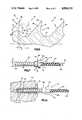
- FIG. 2is an enlarged cross sectional fragmentary view taken approximately along line 2--2 of FIG. 1;
- FIG. 3is an enlarged schematic view, partially in section, illustrating the bone screw in FIG. 1 connecting a corrective device to a bone;
- FIG. 4is a schematic view, partially in section, illustrating a fractured femur before a bone screw is installed
- FIG. 5is a schematic view similar to FIG. 4 illustrating a bone screw and nut installed
- FIG. 6is an enlarged cross sectional fragmentary view of a portion of the bone screw in FIG. 2;
- FIG. 7is an enlarged elevational view illustrating a bone screw according to another embodiment of the present invention.
- FIG. 8is an enlarged view, partly in section, illustrating the bone screw in FIG. 7 partially threaded into a vertebra
- FIG. 9is a view, similar to FIG. 8, illustrating the bone screw attaching a connecting member of a corrective device to a vertebra;
- FIG. 10is an enlarged view of a portion of FIG. 9.
- FIG. 11is an enlarged cross sectional fragmentary view of the bone screw in FIG. 7, taken approximately along line 11--11 in FIG. 7.
- the bone screw 10illustrated in FIG. 1, connects a corrective device to a bone or connects fractured parts of the same bone together.
- the bone screw 10has a mounting section or coarse threaded portion 14 and a connector section or standard threaded portion 16 coaxially arranged along a shank 22.
- the shank 22has an elongate cylindrical shape.
- the bone screw 10is made from a material that is compatible with human bone tissue. Preferably, such a material is a titanium based alloy or a surgical grade stainless steel.
- the coarse threaded portion 14has an external mounting thread convolution for engaging a cancellous bone.
- the standard threaded portion 16receives a connecting member of a corrective device, such as a spine plate 34, and a standard nut 32 (FIG. 3). The nut 32 is tightened on the bone screw 10 to clamp the spine plate 34 to a vertebra 36.
- the bone screw 10also has a driving end portion 26 and a tapered end portion 28 located at axially opposite ends.
- the driving end portion 26is used for rotating the bone screw 10 to advance the bone screw into the vertebra 36.
- the driving end portion 26has an external hex head configuration, but other configurations could be adapted equally well. For example, a hex socket or a standard slotted screw head could be used.
- the tapered end portion 28aligns the bone screw 10 in an opening 42 in the vertebra 36.
- the tapered end portion 28also allows crests of the coarse threads 14 on the tapered portion to gradually engage the surface defining the opening 42 and advance the bone screw 10 upon rotation of the bone screw.
- the coarse threaded portion 14 and standard threaded portion 16each have one thread spirally arranged on the exterior of the shank 22.
- the shank 22has a longitudinal central axis A.
- the configuration of the coarse threaded portion 14is illustrated in detail in FIGS. 2 and 6.
- the coarse threaded portion 14has a leading face 46 and a trailing face 48 relative to the direction the bone screw 10 advances into the vertebra 36, to the left as viewed in FIGS. 2 and 6.
- the leading face 46faces forward in a direction away from the standard threaded portion 16 and is angled to the rear of the bone screw 10 between 40° and 50°.
- the leading face 46is disposed at a 45° angle relative to a line 52 normal to the longitudinal central axis A, or 45 degrees relative to the longitudinal central axis.
- the trailing face 48faces toward the standard threaded portion 16 and is angled to the rear of the bone screw 10 between 5° and 15°.
- the trailing face 48is disposed at a 10° angle relative to the line 52 normal to the longitudinal central axis A, or 80 degrees relative to the longitudinal central axis.
- An arcuate root portion 54 having a radius R(FIG. 6) is formed between the faces 46, 48 of adjacent thread convolutions.
- the leading face 46 and trailing face 48 of the same thread convolutionintersect to form a crest 56.
- the trailing face 48slopes rearwardly and radially outwardly from the arcuate root portion 54 to the crest 56.
- the crest 56is offset rearwardly from the forwardmost portion 48a of the trailing face 48 by a distance Q which is less than the radius R of curvature of the arcuate root portion 54 to form a rearwardly facing recess 58.
- the recess 58is formed between the crest 56 and the arcuate root portion 54. A portion of the cancellous bone extends into the recess 58 and is trapped by the recess. If a force attempts to move the bone screw 10 axially to the right, as viewed in FIG. 6, the crests 56 are impaled in the cancellous bone and the portion of the cancellous bone trapped in the recess 58 must be forced rearwardly and radially outwardly of the recess before the bone screw may move to the right.
- a relatively wide opening 59is formed between the crests 56 of adjacent thread convolutions of the coarse threaded portion 14.
- a portion of the cancellous bone in which the bone screw 10 is usedprojects into the relatively wide opening 59 between crests 56 of adjacent threads on opposite sides of a radial plane P.
- the plane Pextends through a center of curvature C of the arcuate root portion 54 and perpendicular to the longitudinal central axis A of the bone screw 10 and does not intersect any portion of a thread convolution of the coarse threaded portion 14.
- the thread configuration of the threaded portion 14allows a relatively thick portion of the cancellous bone to extend into the relatively wide opening 59 between the adjacent crests 56.
- a relatively strong portion of the cancellous boneforms a solid mounting for the bone screw 10 in the bone.
- a line L extending perpendicular to the leading face 46 of one of the thread convolutions of the coarse threaded portion 14 and extending through the crest 56 of the next forward adjacent thread convolutionis disposed radially outwardly from the center of curvature C of an arcuate root portion 54.
- the distance that the line L extends radially outwardly of the center of curvature C of the arcuate root portion 54is less than the radius R of the arcuate root portion.
- the coarse threaded portion 14has a crest diameter of approximately 0.25 inch and a pitch of 10 threads per inch extending for approximately 11/4 inches along the shank 22.
- the standard thread portion 16is a 10-32 NF-2 thread of 3/16 inch diameter extending for approximately 11/2 inches along the shank 22.
- the drive portion 26has a hexagonal head configuration for gripping with a suitable tool (not shown). The width across the corners of the driving portion 26 is slightly smaller than the root diameter of the standard thread portion 16 to allow the nut 32 pass over the driving portion.
- an opening 42is formed in the vertebra 36.
- the opening 42will have a diameter which is at least as large as the shank 22.
- the opening 42will extend slightly deeper into the vertebra 36 than the depth that the coarse threaded portion 14 will extend.
- the opening 42is then tapped with a tap having a thread profile which is approximately the same as the thread configuration of the coarse threaded portion 14. It has been found that the bone screw 10 requires a larger axial force to remove it from the vertebra 36 if the opening 42 is tapped before the bone screw is threaded into the opening than if the opening is not tapped.
- the bone screw 10is then placed in the opening 42 and gripped with a suitable tool at the driving portion 26.
- the toolis rotated about the longitudinal central axis A of the bone screw 10 so the bone screw advances (to the left as viewed in FIG. 3) relative to the vertebra 36.
- the bone screw 10is rotated until the bone screw extends a desired distance into the vertebra 36, then the tool is removed.
- the spine plate 34is connected to the vertebra 36 by placing the spine plate on the bone screw 10 so the standard thread portion 16 of the bone screw 10 extends through an opening 56 in the spine plate.
- the nut 32is then threaded onto the standard thread portion 16 and tightened against the spine plate 34 to firmly clamp the spine plate against the vertebra 36. Tightening the nut 32 against the spine plate 34 also applies a tensile force to the bone screw 10 attempting to pull the bone screw axially to the right, as viewed in FIG. 3.
- the coarse threaded portion 14 engaging the vertebra 36prevents removal of the bone screw 10.
- the standard thread portion 16 of bone screw 10is then trimmed off adjacent to the nut 32.
- FIG. 5illustrates the bone screw 60 reducing a fracture 62 of the femoral neck. This is accomplished by first drilling an opening 64 (FIG. 4) completely through the upper portion 68 of the femur and partially through the ball portion 66. It will be obvious to one skilled in the art that the opening 64 must be drilled coaxially in the two fractured parts so that when the fracture 62 is reduced, the fractured surfaces will mate to assure proper healing.
- the bone screw 60is then rotated as described above to advance the coarse threaded portion 74 to the position illustrated in FIG. 5.
- the coarse threaded portion 74has a thread configuration similar to that described above. However, the coarse threaded portion 74 extends for a length of about 1/2 to 3/4 of an inch along the shank. This assures that the coarse threaded portion 74 engages only the ball portion 66 side of the fracture 62.
- the standard thread portion 76extends for about two inches through opening 64. A nut 92 and washer 94 are received on the standard thread portion 76. The nut 92 is tightened so that the washer 94 engages the upper portion 68 of the femur in order to move and clamp the fractured parts 66, 68 together.
- FIG. 7Another embodiment of a bone screw 110 according to the present invention is illustrated in FIG. 7.
- the bone screw 110is for use with a connecting member 120 (FIG. 9) of a corrective device for connecting bone portions together.
- the bone screw 110is threaded into a bone portion 122 to connect the connecting member 120 with the bone portion.
- the bone portionsmay be parts of a fractured bone or may be different bones of a group of bones, such as vertebrae of a spinal column.
- the bone screw 110is made from a material compatible with human tissue, such as surgical grade stainless steel or titanium.
- the bone screw 110includes an elongate cylindrical shank 132 (FIG. 11) having a longitudinal central axis B.
- the bone screw 110has an externally threaded portion 142 integrally formed on the shank 132 and extending longitudinally along a portion of the shank.
- the threaded portion 142 of the bone screw 110is identical to the standard threaded portion 16 of the bone screw 10, described above.
- the threaded portion 142receives a standard internally threaded nut 146 (FIG. 9) to secure the connecting member 120 to the bone screw 110.
- the bone screw 110also has another externally threaded portion 144 integrally formed on the shank 132 and extending longitudinally along another portion of the shank.
- the threaded portion 144 of the bone screw 110is identical to the coarse threaded portion 14 of the bone screw 10 (FIG. 1), described above.
- the threaded portion 144is for connecting the bone screw 110 to a cancellous bone portion 122, such as a vertebra, as illustrated in FIGS. 8-10.
- the thread of the threaded portion 144has a crest diameter D 2 (FIG. 7) which is larger than the crest diameter D 5 of the thread of the threaded portion 142.
- the threaded portion 144has a tapered end portion 152 which pilots the bone screw 110 in an opening 154 (FIG. 9) formed in the bone portion 122.
- the opening 154is defined by a surface having a diameter D 6 (FIG. 8) and preferably has a thread 156 tapped in the opening prior to threading the bone screw 110 into the bone portion 122.
- the tapped thread 156preferably has the same configuration as the threaded portion 144 of the bone screw 110.
- the crest diameter D 2 of the threaded portion 144preferably at least as large as the diameter D 6 (FIG. 8) of the opening 154.
- the last three thread convolutions 144a, 144b, 144c (FIG. 10) of the threaded portion 144are formed so the radii Ra, Rb, Rc, respectively, of the root of each thread convolution increases as the thread progresses toward the right, as illustrated in FIG. 11.
- the root radii Ra, Rb, Rc of the last three thread convolutions 144a, 144b 144care greater than the root radius Rr of the other threads on the threaded portion 144.
- the radii Ra, Rb, Rc of the roots of the thread convolutions 144a, 144b, 144cpreferably increase along a line disposed at an angle relative to the longitudinal central axis B of at least 1°.
- the increased radii Ra, Rb, Rcprovides the bone screw 110 with additional strength in the area of the last three thread convolutions 144a, 144b, 144c.
- the forceacts on a cross-sectional area, taken in a plane perpendicular to the longitudinal central axis B, which is larger than the cross-sectional area of the bone screw taken through a portion of a thread convolution having a root radius Rr.
- the bone screw 110also has a drive portion 162 (FIG. 9) for engagement with a suitable tool (not shown), such as a wrench.
- the drive portion 162is located at an axial end portion of the bone screw 110 adjacent the first threaded portion 142.
- a forceis applied through the tool to the drive portion 162 to rotate the bone screw 110 about its longitudinal central axis B (FIG. 11)
- the threaded portion 144advances or threads into the tapped thread 156 in the opening 154 (FIG. 8) in the bone portion 122.
- the interaction of the crests 172 and trailing face 176 of the threaded portion 144 with the cancellous tissue of the bone portion 122prevents the bone screw 110 from being removed from the bone portion by forces acting to move the bone screw axially to the right, as viewed in FIG. 9, relative to the bone portion.
- the bone screw 110includes a cylindrical body portion 182 (FIG. 7) located between the threaded portions 142, 144.
- the cylindrical body portion 182is defined by a surface having a diameter D 1 which is substantially equal to the crest diameter D 2 of the threaded portion 144 and, thus, is larger than the diameter D 6 (FIG. 8) of the opening 154.
- the axial extent Y (FIG. 8) or length of the body portion 182is preferably less than the pitch X of the threaded portion 144.
- the body portion 182forces a portion of the cancellous bone tissue of the bone portion 122 adjacent the tapped thread 156 forward and radially outward into the tapped thread so no radial clearance exists between the body portion and the surface of the opening.
- the axial extent Y of the body portion 182is shorter than the pitch X of the threaded portion 144, and thus is shorter than the pitch of the tapped thread 156, to assure that a minimum amount of deformation of the bone portion 122 occurs adjacent the opening 154. If too much deformation of the bone portion 122 is caused by the bone screw 110, damage to the bone portion could result.
- the body portion 182thus, is in circumferential engagement with the surface defining the opening 154 in the bone portion 122.
- the body portion 182restricts the bone screw 110 from moving relative to the bone portion 122 in a direction transversely to the longitudinal central axis B of the bone screw.
- the body portion 182also seals or restricts the flow of body fluids from the opening 154 to the areas of the bone screw outside the bone portion 122 which are normally subjected to the highest stress.
- An alternate drive portion 192 having a hex head configurationis formed on the shank 132 between the threaded portion 142 and the body portion 182.
- the drive portion 192is engageable by a suitable tool to prevent the rotation of the bone screw 110 during tightening of the nut 146 on the threaded portion 142.
- the drive portion 192may also be used to remove the bone screw 110 after the connecting member 120 is removed from a patient, as is typically done in the case of a relatively young patient who has recovered from the injury or damage that the connecting member was used to correct.
- a shoulder portion 184(FIG. 7) is disposed adjacent the body portion 182 between the alternate drive portion 192 and the body portion 182.
- the shoulder portion 184acts to eliminate any stress risers which could result from a stepped transition between the body portion 182 and the alternate drive portion 192.
- the shoulder portion 184is defined by a circular and axially tapered surface.
- the tapered surface of the shoulder portion 184has a diameter D 3 which increases as the tapered surface extends in a direction from the body portion 182 toward the alternate drive portion 192.
- the diameter D 3 of the tapered surface of the shoulder portion 184is greater than the diameter D 2 of the body portion 182.
- the tapered surface of the shoulder portion 184engages the circumferential edge 180 at the end of the opening 154 to further aid in preventing movement or "wobble" of the bone screw relative to the bone portion. Since the body portion 182 engages a circumferential portion of a portion of the surface defining the opening 154 and the shoulder portion 184 engages the circumferential edge 180 of the opening 154, a seal is created between the part of the bone screw 110 extending from the opening 154 and the bone portion 122. The sealing action of the body portion 182 and shoulder portion 184 restricts the flow of body fluids from the opening 154 in the bone portion 122. Thus, the flow of corrosive body fluids from the opening 154 in the bone portion 122 is further blocked to prevent corrosion to the bone screw 110 in the areas of highest stress, which are typically located between the threaded portions 142, 144.
- the shoulder portion 184also provides a bone screw 110 with a relatively shorter moment arm between its rightmost engagement point with the edge 180 of the bone portion 122, as viewed in FIG. 9, and the connecting member 120 than if no shoulder portion was present. If no shoulder portion was present, the rightmost engagement point of the bone screw and bone portion, about which the bone screw tends to bend, would be inside the bone portion.
- a relatively strong bone screw 110is provided since the shoulder portion 184 has a relatively large cross-section, taken perpendicularly to the longitudinal central axis B at the engagement point 180, to distribute the force over a relatively large area tending to bend the bone screw about the edge 180.
- the shoulder portion 184also forms a reference surface integrally formed on the bone screw 110. The reference surface enables the surgeon to know how far the threaded portion 144 extends into the bone portion 122 since the length that the threaded portion extends from the shoulder portion 184 is known before threading the bone screw 110 into the bone portion.
- a seat portion 194has a planar surface integrally formed at an axial end of the alternate drive portion 192 adjacent the threaded portion 142.
- the seat portion 194engages the connecting member 120 to establish the axial location of the connecting member along the bone screw 110 and to space the connecting member from the bone portion 122.
- Forming the seat portion 194 integrally on the bone screw 110assures that the surface engaged by the connecting member 120 will not loosen and move relative to the bone screw after the surgical procedure so the location of the connecting member 120 along the bone screw does not change.
- Another shoulder portion 202extends between the seat portion 194 and the threaded portion 142.
- the shoulder portion 202eliminates any stress risers which could result from a stepped transition between the seat portion 194 and the threaded portion 142.
- the shoulder portion 202is defined by a circular and axially tapered surface.
- the tapered surface of the shoulder portion 202has a diameter D 4 that increases as the shoulder portion extends from the threaded portion 142 to the seat portion 194.
- the diameter D 4 of the tapered surface defining the shoulder portion 202is greater than the crest diameter D 5 of the threaded portion 142.
- the increasing diameter D 4 of the shoulder portion 202thus, provides a relatively large cross-sectional area, taken perpendicular to the longitudinal central axis B, over which to distribute the forces to reduce the stress and provide a bone screw 110 less prone to failure.
- a spacemay result between the seat portion 194 and the connecting member. If the nut 146 is tightened against the connecting member 120, stress may concentrate in the portion of the bone screw 110 adjacent the seat portion 194 by the threaded portion 142 attempting to bend or pivot relative the threaded portion 144.
- a washer 204 having an angled or wedge-shaped configurationis preferably used between the seat portion 194 and the connecting member 120. The configuration or angle of the washer 204 is chosen to closely match the angle of the space between the connecting member 120 and the seat portion 194. The connecting member 120 will contact the entire angled surface 206 of the washer 204 and evenly distribute load over the surface area of the seat portion 194 so the threaded portion 142 does not tend to bend relative to the threaded portion 144.
Landscapes
- Health & Medical Sciences (AREA)
- Orthopedic Medicine & Surgery (AREA)
- Life Sciences & Earth Sciences (AREA)
- Surgery (AREA)
- Neurology (AREA)
- Heart & Thoracic Surgery (AREA)
- Engineering & Computer Science (AREA)
- Biomedical Technology (AREA)
- Nuclear Medicine, Radiotherapy & Molecular Imaging (AREA)
- Medical Informatics (AREA)
- Molecular Biology (AREA)
- Animal Behavior & Ethology (AREA)
- General Health & Medical Sciences (AREA)
- Public Health (AREA)
- Veterinary Medicine (AREA)
- Surgical Instruments (AREA)
- Vehicle Body Suspensions (AREA)
- Shafts, Cranks, Connecting Bars, And Related Bearings (AREA)
Abstract
Description
Claims (16)
Priority Applications (7)
| Application Number | Priority Date | Filing Date | Title |
|---|---|---|---|
| US07/146,739US4854311A (en) | 1986-01-09 | 1988-01-21 | Bone screw |
| CA000569173ACA1294501C (en) | 1988-01-21 | 1988-06-10 | Bone screw |
| DE198888109604TDE325682T1 (en) | 1988-01-21 | 1988-06-16 | BONE SCREW. |
| DE88109604TDE3885731T2 (en) | 1988-01-21 | 1988-06-16 | Bone screw. |
| EP88109604AEP0325682B1 (en) | 1988-01-21 | 1988-06-16 | Bone screw |
| ES198888109604TES2023085T3 (en) | 1988-01-21 | 1988-06-16 | SCREW OSEO. |
| JP63194316AJPH01192345A (en) | 1988-01-21 | 1988-08-03 | Screw for bone |
Applications Claiming Priority (2)
| Application Number | Priority Date | Filing Date | Title |
|---|---|---|---|
| US81734486A | 1986-01-09 | 1986-01-09 | |
| US07/146,739US4854311A (en) | 1986-01-09 | 1988-01-21 | Bone screw |
Related Parent Applications (1)
| Application Number | Title | Priority Date | Filing Date |
|---|---|---|---|
| US81734486AContinuation-In-Part | 1986-01-09 | 1986-01-09 |
Publications (1)
| Publication Number | Publication Date |
|---|---|
| US4854311Atrue US4854311A (en) | 1989-08-08 |
Family
ID=22518788
Family Applications (1)
| Application Number | Title | Priority Date | Filing Date |
|---|---|---|---|
| US07/146,739Expired - LifetimeUS4854311A (en) | 1986-01-09 | 1988-01-21 | Bone screw |
Country Status (6)
| Country | Link |
|---|---|
| US (1) | US4854311A (en) |
| EP (1) | EP0325682B1 (en) |
| JP (1) | JPH01192345A (en) |
| CA (1) | CA1294501C (en) |
| DE (2) | DE3885731T2 (en) |
| ES (1) | ES2023085T3 (en) |
Cited By (144)
| Publication number | Priority date | Publication date | Assignee | Title |
|---|---|---|---|---|
| DE4010977C1 (en)* | 1990-04-05 | 1991-11-14 | Aesculap Ag, 7200 Tuttlingen, De | |
| US5113685A (en)* | 1991-01-28 | 1992-05-19 | Acromed Corporation | Apparatus for contouring spine plates and/or rods |
| US5222954A (en)* | 1991-06-21 | 1993-06-29 | Artifex, Ltd. | Spinal implant system and method for installing the implant |
| US5282862A (en)* | 1991-12-03 | 1994-02-01 | Artifex Ltd. | Spinal implant system and a method for installing the implant onto a vertebral column |
| US5375956A (en)* | 1993-03-11 | 1994-12-27 | Pennig; Dietmar | Head screw construction for use in fixing the position of an intramedullary nail |
| US5443564A (en)* | 1994-04-14 | 1995-08-22 | Reaves; Donald G. | Tie rod loosening tool for use with a tie rod assembly |
| US5476463A (en)* | 1994-01-12 | 1995-12-19 | Acromed Corporation | Spinal column retaining apparatus |
| EP0706876A1 (en) | 1994-10-14 | 1996-04-17 | Acromed Corporation | Composite structure and method of forming same |
| US5569248A (en)* | 1992-03-17 | 1996-10-29 | Danek Medical, Inc. | Apparatus for subcutaneous suprafascial pedicular internal fixation |
| US5613967A (en)* | 1995-04-28 | 1997-03-25 | Acromed Corporation | Apparatus for maintaining bone portions in a desired spatial relationship |
| US5688275A (en)* | 1996-02-09 | 1997-11-18 | Koros; Tibor | Spinal column rod fixation system |
| US5728127A (en)* | 1995-06-27 | 1998-03-17 | Acro Med Corporation | Apparatus for maintaining vertebrae of a spinal column in a desired spatial relationship |
| US5735653A (en)* | 1996-03-07 | 1998-04-07 | Hilti Aktiengesellschaft | Anchor rod for composite anchors |
| EP0888754A1 (en) | 1997-07-03 | 1999-01-07 | Acromed Corporation | Osteosynthetic Fastener |
| US5871486A (en)* | 1993-01-21 | 1999-02-16 | Acumed, Inc. | Variable pitch bone screw |
| US5891146A (en)* | 1997-10-15 | 1999-04-06 | Applied Biological Concepts, Inc. | Wedge orthopedic screw |
| US5899902A (en)* | 1997-07-03 | 1999-05-04 | Depuy Motech Acromed Corporation | Fastener |
| US5964768A (en)* | 1993-01-21 | 1999-10-12 | Acumed, Inc. | Tapered bone screw with continuously varying pitch |
| US6004322A (en)* | 1994-10-25 | 1999-12-21 | Sdgi Holdings, Inc. | Modular pedicle screw system |
| US6030162A (en)* | 1998-12-18 | 2000-02-29 | Acumed, Inc. | Axial tension screw |
| DE19912364A1 (en)* | 1999-03-19 | 2000-10-12 | Peter Brehm | Screw to fix reinforcement rod along spinal column; has U-shaped recess for reinforcement rod with saw-tooth thread having surfaces at negative angle to secure fixing screw |
| US6146384A (en)* | 1995-10-13 | 2000-11-14 | Sdgi Holdings, Inc. | Orthopedic fixation device and method of implantation |
| US6176861B1 (en) | 1994-10-25 | 2001-01-23 | Sdgi Holdings, Inc. | Modular spinal system |
| US6248107B1 (en) | 2000-03-15 | 2001-06-19 | Sdgi Holdings, Inc. | System for reducing the displacement of a vertebra |
| US6299615B1 (en) | 1993-01-21 | 2001-10-09 | Acumed, Inc. | System for fusing joints |
| US6302883B1 (en) | 1998-10-22 | 2001-10-16 | Depuy Acromed, Inc. | Bone plate-ratcheting compression apparatus |
| WO2002043601A3 (en)* | 2000-11-22 | 2002-08-22 | Milorad Mitkovic | Internal fixator of bones |
| US20020136595A1 (en)* | 1998-12-30 | 2002-09-26 | Schubring Gary L. | Double ended fastening system |
| US6468277B1 (en) | 2000-04-04 | 2002-10-22 | Ethicon, Inc. | Orthopedic screw and method |
| US6468309B1 (en) | 2000-10-05 | 2002-10-22 | Cleveland Clinic Foundation | Method and apparatus for stabilizing adjacent bones |
| US6478798B1 (en) | 2001-05-17 | 2002-11-12 | Robert S. Howland | Spinal fixation apparatus and methods for use |
| US6488683B2 (en) | 2000-11-08 | 2002-12-03 | Cleveland Clinic Foundation | Method and apparatus for correcting spinal deformity |
| US20030014054A1 (en)* | 1993-01-21 | 2003-01-16 | Huebner Randall J. | System for fusing joints |
| US6527774B2 (en) | 2000-11-08 | 2003-03-04 | The Cleveland Clinic Foundation | Apparatus for attaching fractured sections of bone |
| US6530731B2 (en)* | 2001-02-01 | 2003-03-11 | General Dynamics Land Systems, Inc. | Self-tapping insert, insert assembly, and method for mounting the insert |
| US6544265B2 (en) | 2000-11-08 | 2003-04-08 | The Cleveland Clinic Foundation | Apparatus for implantation into bone related applications |
| US6547564B1 (en)* | 1998-07-17 | 2003-04-15 | Astra Aktiebolag | Bone implant having circumferentially oriented roughness |
| US6551319B2 (en) | 2000-11-08 | 2003-04-22 | The Cleveland Clinic Foundation | Apparatus for implantation into bone |
| US6551320B2 (en) | 2000-11-08 | 2003-04-22 | The Cleveland Clinic Foundation | Method and apparatus for correcting spinal deformity |
| US6551322B1 (en) | 2000-10-05 | 2003-04-22 | The Cleveland Clinic Foundation | Apparatus for implantation into bone |
| US20030153919A1 (en)* | 2002-02-12 | 2003-08-14 | Harris Peter M. | Self-locking bone screw and implant |
| US20030181913A1 (en)* | 2000-10-05 | 2003-09-25 | The Cleveland Clinic Foundation | Apparatus for implantation into bone |
| US6635086B2 (en) | 2000-05-30 | 2003-10-21 | Blacksheep Technologies Incorporated | Implant for placement between cervical vertebrae |
| US20030215564A1 (en)* | 2001-01-18 | 2003-11-20 | Heller Phillip F. | Method and apparatus for coating an endoprosthesis |
| US6666638B2 (en) | 2001-02-15 | 2003-12-23 | Phillips Screw Company | Deck screw having multiple threaded sections |
| US20040097941A1 (en)* | 2002-11-20 | 2004-05-20 | Millennium Medical Technologies Inc. | Compression bone fragment wire |
| US6758512B2 (en)* | 2002-08-01 | 2004-07-06 | Alan Dobbs | Window frame stud |
| US6770075B2 (en) | 2001-05-17 | 2004-08-03 | Robert S. Howland | Spinal fixation apparatus with enhanced axial support and methods for use |
| US20040158251A1 (en)* | 1999-04-16 | 2004-08-12 | Morrison Matthew M. | Multi-axial bone anchor system |
| US20040167519A1 (en)* | 2002-11-20 | 2004-08-26 | Millennium Medical Technologies, Inc. | Convertible threaded compression device and method of use |
| US20040193161A1 (en)* | 2001-10-03 | 2004-09-30 | Vaughan Paul A. | Vertebral stabilization assembly and method |
| US20040197139A1 (en)* | 2001-08-06 | 2004-10-07 | Mcgovern Hubert T. | Deck screws suitable for use with composite lumber |
| US20040228705A1 (en)* | 2003-05-16 | 2004-11-18 | Abbott-Interfast Corporation. | Fasteners for composite material |
| US6827538B2 (en)* | 2001-09-10 | 2004-12-07 | Htg-Wyandotte, Llc | Torque prevailing stud |
| US20050033431A1 (en)* | 2003-08-05 | 2005-02-10 | Charles Gordon | Artificial functional spinal unit assemblies |
| US20050033432A1 (en)* | 2003-08-05 | 2005-02-10 | Charles Gordon | Artificial spinal unit assemblies |
| US20050033439A1 (en)* | 2003-08-05 | 2005-02-10 | Charles Gordon | Artificial functional spinal unit assemblies |
| US20050209698A1 (en)* | 2003-08-05 | 2005-09-22 | Gordon Charles R | Expandable intervertebral implant |
| US20060095037A1 (en)* | 2004-10-29 | 2006-05-04 | Jones Bryan S | Connector assemblies for connecting a bone anchor to a fixation element |
| US20060217716A1 (en)* | 2005-03-22 | 2006-09-28 | Baker Daniel R | Spinal fixation locking mechanism |
| US20060229729A1 (en)* | 2003-08-05 | 2006-10-12 | Gordon Charles R | Expandable intervertebral implant for use with instrument |
| US20060241771A1 (en)* | 2003-08-05 | 2006-10-26 | Southwest Research Institute | Artificial functional spinal unit system and method for use |
| US20060247641A1 (en)* | 2004-11-15 | 2006-11-02 | Paul Re | Method and apparatus for the repair of a rotator cuff (RTC) tendon or ligament |
| US20060264933A1 (en)* | 2005-05-04 | 2006-11-23 | Baker Daniel R | Multistage spinal fixation locking mechanism |
| US7141051B2 (en) | 2003-02-05 | 2006-11-28 | Pioneer Laboratories, Inc. | Low profile spinal fixation system |
| US20070100339A1 (en)* | 2003-06-27 | 2007-05-03 | Medicrea Technologies | Vertebral osteosynthesis equipment |
| US20070127982A1 (en)* | 2005-11-15 | 2007-06-07 | Daimlerchrysler Ag | Device for pivotably connecting at least two components and a method for mounting the device |
| US7235079B2 (en) | 2004-11-18 | 2007-06-26 | Acumed Llc | Composite bone fasteners |
| US20070147973A1 (en)* | 2005-12-22 | 2007-06-28 | Cyril Laan | Dual threaded screw for composite materials |
| US20070162017A1 (en)* | 2005-11-28 | 2007-07-12 | Gambale Michael A | Method and apparatus for treatment of bones |
| US20070233063A1 (en)* | 2006-02-15 | 2007-10-04 | Sdgi Holdings, Inc. | Multiple lead bone fixation apparatus |
| US20070288012A1 (en)* | 2006-04-21 | 2007-12-13 | Dennis Colleran | Dynamic motion spinal stabilization system and device |
| US7314467B2 (en) | 2002-04-24 | 2008-01-01 | Medical Device Advisory Development Group, Llc. | Multi selective axis spinal fixation system |
| US20080154314A1 (en)* | 2006-08-16 | 2008-06-26 | Mcdevitt Dennis M | Composite interference screw for attaching a graft ligament to a bone, and other apparatus for making attachments to bone |
| US20080234823A1 (en)* | 2007-01-19 | 2008-09-25 | Landry Michael E | Artificial functional spinal unit system and method for use |
| US20080234760A1 (en)* | 2007-03-23 | 2008-09-25 | Zbigniew Matulaniec | Bone screw apparatus and related methods of use |
| US20080306554A1 (en)* | 2007-06-11 | 2008-12-11 | Mckinley Laurence M | Osseointegration and biointegration coatings for bone screw implants |
| US20090018589A1 (en)* | 2007-07-13 | 2009-01-15 | Smisson Iii Hugh F | Bone Screw |
| US20090018592A1 (en)* | 2007-07-13 | 2009-01-15 | Pitbladdo Richard B | Bone screw for orthopedic apparatus |
| US20090082807A1 (en)* | 2007-09-24 | 2009-03-26 | Miller M Todd | Suture anchor having a suture engaging structure and inserter arrangement |
| US20090105767A1 (en)* | 2007-10-18 | 2009-04-23 | Inbone Technologies, Inc. | Total joint subsidence protector |
| US20090105758A1 (en)* | 2007-10-22 | 2009-04-23 | Gimbel Jonathan A | Dampener system for a posterior stabilization system with a variable length elongated member |
| US20090105828A1 (en)* | 2007-10-22 | 2009-04-23 | Gimbel Jonathan A | Posterior stabilization system with isolated, dual dampener systems |
| US20090105829A1 (en)* | 2007-10-22 | 2009-04-23 | Gimbel Jonathan A | Dampener system for a posterior stabilization system with a variable length elongated member |
| US20090105827A1 (en)* | 2007-10-22 | 2009-04-23 | Gimbel Jonathan A | Dampener system for a posterior stabilization system with a fixed length elongated member |
| US20090105759A1 (en)* | 2007-10-22 | 2009-04-23 | Gimbel Jonathan A | Spinal stabilization systems with dynamic interbody devices |
| US20090105757A1 (en)* | 2007-10-22 | 2009-04-23 | Gimbel Jonathan A | Posterior stabilization systems with shared, dual dampener systems |
| US20090105840A1 (en)* | 2007-10-18 | 2009-04-23 | Inbone Technologies, Inc. | Fibular stiffener and bony defect replacer |
| US20090125071A1 (en)* | 2007-10-23 | 2009-05-14 | Skinlo David M | Shape-changing anatomical anchor |
| US20090319043A1 (en)* | 2007-08-16 | 2009-12-24 | Mcdevitt Dennis | Helicoil interference fixation system for attaching a graft ligament to a bone |
| WO2010093329A1 (en)* | 2009-02-16 | 2010-08-19 | Unisteel Technology Limited | Self-tapping thread forming screw and corresponding thread roll die |
| WO2010124230A1 (en)* | 2009-04-23 | 2010-10-28 | University Of Massachusetts | Bone fixture assembly |
| US7854752B2 (en) | 2004-08-09 | 2010-12-21 | Theken Spine, Llc | System and method for dynamic skeletal stabilization |
| US20110027608A1 (en)* | 2007-11-21 | 2011-02-03 | Danfoss A/S Tantalum Technologies | Object having a ductile and corrosion resistant surface layer |
| US20110082508A1 (en)* | 2009-10-02 | 2011-04-07 | Jason M. Hiatt | Apparatus and Method for Use in the Treatment of Hammertoe |
| US20110118739A1 (en)* | 2008-06-24 | 2011-05-19 | Jeff Tyber | Intramedullary fixation assembly and method of use |
| FR2957239A1 (en)* | 2010-03-09 | 2011-09-16 | Synchro Medical | Surgical screw for repairing bone of patient, has screw thread whose proximal face forms angle with proximal direction of longitudinal axis and greater than or equal to ninety degrees and less than one hundred and eighty degrees |
| US8025681B2 (en) | 2006-03-29 | 2011-09-27 | Theken Spine, Llc | Dynamic motion spinal stabilization system |
| US8070786B2 (en) | 1993-01-21 | 2011-12-06 | Acumed Llc | System for fusing joints |
| US8114158B2 (en) | 2004-08-03 | 2012-02-14 | Kspine, Inc. | Facet device and method |
| US8118869B2 (en) | 2006-03-08 | 2012-02-21 | Flexuspine, Inc. | Dynamic interbody device |
| US8162979B2 (en) | 2007-06-06 | 2012-04-24 | K Spine, Inc. | Medical device and method to correct deformity |
| US8197511B2 (en) | 2007-09-24 | 2012-06-12 | Miller M Todd | Suture anchor having a suture engaging structure and inserter arrangement |
| FR2971413A1 (en)* | 2011-02-15 | 2012-08-17 | Jean-Pierre Py | Cannulated self-tapping screw for osteosynthesis of e.g. hand bone, has threaded distal portion including thread whose proximal edge is inclined toward proximal side of screw and whose outer edge forms sharp edge with distal edge of thread |
| WO2012116819A1 (en)* | 2011-03-03 | 2012-09-07 | Zimmer, Inc | Bone screw with multiple thread profiles for far cortical locking and flexible engagement to a bone |
| US8357183B2 (en) | 2009-03-26 | 2013-01-22 | Kspine, Inc. | Semi-constrained anchoring system |
| US8617216B2 (en) | 2010-04-05 | 2013-12-31 | David L. Brumfield | Fully-adjustable bone fixation device |
| US8790374B2 (en) | 2004-04-08 | 2014-07-29 | Globus Medical, Inc. | Polyaxial screw |
| US8821546B2 (en) | 2007-11-06 | 2014-09-02 | Stanus Investments, Inc. | Vertebral screw arrangement with locking pin |
| US8828058B2 (en) | 2008-11-11 | 2014-09-09 | Kspine, Inc. | Growth directed vertebral fixation system with distractible connector(s) and apical control |
| US8858596B2 (en) | 2012-03-20 | 2014-10-14 | Stryker Corporation | Suture anchor having a suture engaging structure |
| US8888827B2 (en) | 2011-07-15 | 2014-11-18 | Globus Medical, Inc. | Orthopedic fixation devices and methods of installation thereof |
| US8920472B2 (en) | 2011-11-16 | 2014-12-30 | Kspine, Inc. | Spinal correction and secondary stabilization |
| US8940051B2 (en) | 2011-03-25 | 2015-01-27 | Flexuspine, Inc. | Interbody device insertion systems and methods |
| US8979865B2 (en) | 2010-03-10 | 2015-03-17 | Smith & Nephew, Inc. | Composite interference screws and drivers |
| US8992586B2 (en) | 2011-07-20 | 2015-03-31 | Michael H. Horwitz | Minimal incision removable bone screw, driver, and method of use |
| US9046120B2 (en) | 2010-10-01 | 2015-06-02 | Infastech Intellectual Properties Pte. Ltd | Threaded fastener |
| US9078702B1 (en)* | 2014-03-20 | 2015-07-14 | Amendia, Inc. | Spinal alignment correction system and methods of use |
| US9155531B2 (en) | 2013-03-15 | 2015-10-13 | Smith & Nephew, Inc. | Miniaturized dual drive open architecture suture anchor |
| US9161793B2 (en) | 1993-01-21 | 2015-10-20 | Acumed Llc | Axial tension screw |
| US9168071B2 (en) | 2009-09-15 | 2015-10-27 | K2M, Inc. | Growth modulation system |
| US9186187B2 (en) | 2011-07-15 | 2015-11-17 | Globus Medical, Inc. | Orthopedic fixation devices and methods of installation thereof |
| US9198694B2 (en) | 2011-07-15 | 2015-12-01 | Globus Medical, Inc. | Orthopedic fixation devices and methods of installation thereof |
| US9259254B2 (en) | 2004-04-08 | 2016-02-16 | Globus Medical, Inc. | Polyaxial screw |
| US9308080B2 (en) | 2010-03-10 | 2016-04-12 | Smith & Nephew Inc. | Composite interference screws and drivers |
| US9333009B2 (en) | 2011-06-03 | 2016-05-10 | K2M, Inc. | Spinal correction system actuators |
| US9358047B2 (en) | 2011-07-15 | 2016-06-07 | Globus Medical, Inc. | Orthopedic fixation devices and methods of installation thereof |
| US9451987B2 (en) | 2011-11-16 | 2016-09-27 | K2M, Inc. | System and method for spinal correction |
| US9468471B2 (en) | 2013-09-17 | 2016-10-18 | K2M, Inc. | Transverse coupler adjuster spinal correction systems and methods |
| US9468468B2 (en) | 2011-11-16 | 2016-10-18 | K2M, Inc. | Transverse connector for spinal stabilization system |
| US9468469B2 (en) | 2011-11-16 | 2016-10-18 | K2M, Inc. | Transverse coupler adjuster spinal correction systems and methods |
| US9492288B2 (en) | 2013-02-20 | 2016-11-15 | Flexuspine, Inc. | Expandable fusion device for positioning between adjacent vertebral bodies |
| US9517144B2 (en) | 2014-04-24 | 2016-12-13 | Exactech, Inc. | Limited profile intervertebral implant with incorporated fastening mechanism |
| US9526627B2 (en) | 2011-11-17 | 2016-12-27 | Exactech, Inc. | Expandable interbody device system and method |
| US9566098B2 (en) | 2009-04-23 | 2017-02-14 | University Of Massachusetts | Bone fixture assembly |
| US9579188B2 (en) | 2010-03-10 | 2017-02-28 | Smith & Nephew, Inc. | Anchor having a controlled driver orientation |
| US9775702B2 (en) | 2010-03-10 | 2017-10-03 | Smith & Nephew, Inc. | Composite interference screws and drivers |
| US9808298B2 (en) | 2013-04-09 | 2017-11-07 | Smith & Nephew, Inc. | Open-architecture interference screw |
| US9901355B2 (en) | 2011-03-11 | 2018-02-27 | Smith & Nephew, Inc. | Trephine |
| US9924934B2 (en) | 2011-06-07 | 2018-03-27 | Smith & Nephew, Inc. | Surgical anchor delivery system |
| US9993269B2 (en) | 2011-07-15 | 2018-06-12 | Globus Medical, Inc. | Orthopedic fixation devices and methods of installation thereof |
| US20180328399A1 (en)* | 2016-09-13 | 2018-11-15 | Ying-Chin CHAO | Structure of screw |
| US10398565B2 (en) | 2014-04-24 | 2019-09-03 | Choice Spine, Llc | Limited profile intervertebral implant with incorporated fastening and locking mechanism |
| US10702311B2 (en) | 2011-11-16 | 2020-07-07 | K2M, Inc. | Spinal correction and secondary stabilization |
Families Citing this family (11)
| Publication number | Priority date | Publication date | Assignee | Title |
|---|---|---|---|---|
| JPH066810Y2 (en)* | 1989-11-29 | 1994-02-23 | 旭光学工業株式会社 | Vertebral body fixation plate |
| DE3942326A1 (en)* | 1989-12-21 | 1991-06-27 | Haerle Anton | SCREW AS AN OSTEOSYNTHESIS TOOL |
| JPH04138152A (en)* | 1990-09-29 | 1992-05-12 | Ikufumi Yamada | Internal fixing tool for collum humeri fracture |
| DE4136178A1 (en)* | 1991-11-02 | 1993-05-06 | Deutsche Thomson-Brandt Gmbh, 7730 Villingen-Schwenningen, De | CIRCUIT FOR CONTINUOUS ZOOM ADJUSTMENT OF PICTURE WIDTH IN A TELEVISION RECEIVER |
| WO1993012151A1 (en)* | 1991-12-13 | 1993-06-24 | Exxon Chemical Patents Inc. | Ethylene/longer alpha-olefin copolymers |
| WO1999011177A2 (en)* | 1997-09-05 | 1999-03-11 | Deslauriers Richard J | Self-retaining anchor track and method of making and using same |
| KR20030037616A (en)* | 2001-11-07 | 2003-05-14 | 주식회사 코렌텍 | Free length hip pin |
| EP1420298B1 (en) | 2002-11-12 | 2013-02-20 | ASML Netherlands B.V. | Lithographic apparatus |
| WO2012074991A1 (en) | 2010-11-30 | 2012-06-07 | Amit Sinha | Bone compression and fixation devices |
| ITTO20120104A1 (en)* | 2012-02-08 | 2013-08-09 | Twocare S R L | DENTAL PLANT OR BONE |
| AT517141B1 (en)* | 2015-04-15 | 2019-08-15 | Pastl Klaus | bone screw |
Citations (16)
| Publication number | Priority date | Publication date | Assignee | Title |
|---|---|---|---|---|
| US272778A (en)* | 1883-02-20 | William schilling | ||
| GB189313867A (en)* | 1893-07-18 | 1893-11-25 | George Augustus Macnutt | An Improved Screw for Woodwork and other purposes. |
| US1801186A (en)* | 1929-04-18 | 1931-04-14 | Internat Screw Co | Single-point, double-thread drive screw |
| US2121193A (en)* | 1932-12-21 | 1938-06-21 | Hanicke Paul Gustav Erich | Fracture clamping apparatus |
| US2570465A (en)* | 1949-08-01 | 1951-10-09 | Joseph S Lundholm | Means for fixation of hip fractures |
| US3489143A (en)* | 1967-12-15 | 1970-01-13 | William X Halloran | Convertible hip pin |
| US3660233A (en)* | 1969-11-12 | 1972-05-02 | Gen Electric | Nuclear reactor upper core grid |
| US3693616A (en)* | 1970-06-26 | 1972-09-26 | Robert Roaf | Device for correcting scoliotic curves |
| US3706309A (en)* | 1971-04-29 | 1972-12-19 | Irwing N Toftness | Device for applying and releasing pressure |
| US3997138A (en)* | 1974-06-18 | 1976-12-14 | Henry Vernon Crock | Securing devices and structures |
| US4175555A (en)* | 1977-02-24 | 1979-11-27 | Interfix Limited | Bone screw |
| US4448191A (en)* | 1981-07-07 | 1984-05-15 | Rodnyansky Lazar I | Implantable correctant of a spinal curvature and a method for treatment of a spinal curvature |
| US4456005A (en)* | 1982-09-30 | 1984-06-26 | Lichty Terry K | External compression bone fixation device |
| SU1115738A1 (en)* | 1983-05-10 | 1984-09-30 | Кемеровский государственный медицинский институт | Fixative of femur neck |
| US4493317A (en)* | 1980-11-20 | 1985-01-15 | Synthes Ltd. (U.S.A.) | Surgical compression plate and drill guide |
| US4655199A (en)* | 1985-03-29 | 1987-04-07 | Acromed Corporation | Spinal column straightening apparatus |
Family Cites Families (6)
| Publication number | Priority date | Publication date | Assignee | Title |
|---|---|---|---|---|
| GB913039A (en)* | 1961-10-03 | 1962-12-12 | Down Bros And Meyer & Phelps L | Improvements in and relating to surgical implants |
| GB2108229B (en)* | 1981-10-16 | 1985-10-30 | Howse And Company Limited D | Bone fixation screws |
| US4611581A (en)* | 1983-12-16 | 1986-09-16 | Acromed Corporation | Apparatus for straightening spinal columns |
| US4612920A (en)* | 1984-11-06 | 1986-09-23 | Zimmer, Inc. | Compression hip screw |
| US4653481A (en)* | 1985-07-24 | 1987-03-31 | Howland Robert S | Advanced spine fixation system and method |
| DE3538593A1 (en)* | 1985-10-30 | 1987-05-07 | Thomas Dr Med Jungeblod | Device for the surgical treatment of bones, especially of fractured bones |
- 1988
- 1988-01-21USUS07/146,739patent/US4854311A/ennot_activeExpired - Lifetime
- 1988-06-10CACA000569173Apatent/CA1294501C/ennot_activeExpired - Lifetime
- 1988-06-16DEDE88109604Tpatent/DE3885731T2/ennot_activeExpired - Lifetime
- 1988-06-16ESES198888109604Tpatent/ES2023085T3/ennot_activeExpired - Lifetime
- 1988-06-16DEDE198888109604Tpatent/DE325682T1/enactivePending
- 1988-06-16EPEP88109604Apatent/EP0325682B1/ennot_activeExpired - Lifetime
- 1988-08-03JPJP63194316Apatent/JPH01192345A/enactiveGranted
Patent Citations (16)
| Publication number | Priority date | Publication date | Assignee | Title |
|---|---|---|---|---|
| US272778A (en)* | 1883-02-20 | William schilling | ||
| GB189313867A (en)* | 1893-07-18 | 1893-11-25 | George Augustus Macnutt | An Improved Screw for Woodwork and other purposes. |
| US1801186A (en)* | 1929-04-18 | 1931-04-14 | Internat Screw Co | Single-point, double-thread drive screw |
| US2121193A (en)* | 1932-12-21 | 1938-06-21 | Hanicke Paul Gustav Erich | Fracture clamping apparatus |
| US2570465A (en)* | 1949-08-01 | 1951-10-09 | Joseph S Lundholm | Means for fixation of hip fractures |
| US3489143A (en)* | 1967-12-15 | 1970-01-13 | William X Halloran | Convertible hip pin |
| US3660233A (en)* | 1969-11-12 | 1972-05-02 | Gen Electric | Nuclear reactor upper core grid |
| US3693616A (en)* | 1970-06-26 | 1972-09-26 | Robert Roaf | Device for correcting scoliotic curves |
| US3706309A (en)* | 1971-04-29 | 1972-12-19 | Irwing N Toftness | Device for applying and releasing pressure |
| US3997138A (en)* | 1974-06-18 | 1976-12-14 | Henry Vernon Crock | Securing devices and structures |
| US4175555A (en)* | 1977-02-24 | 1979-11-27 | Interfix Limited | Bone screw |
| US4493317A (en)* | 1980-11-20 | 1985-01-15 | Synthes Ltd. (U.S.A.) | Surgical compression plate and drill guide |
| US4448191A (en)* | 1981-07-07 | 1984-05-15 | Rodnyansky Lazar I | Implantable correctant of a spinal curvature and a method for treatment of a spinal curvature |
| US4456005A (en)* | 1982-09-30 | 1984-06-26 | Lichty Terry K | External compression bone fixation device |
| SU1115738A1 (en)* | 1983-05-10 | 1984-09-30 | Кемеровский государственный медицинский институт | Fixative of femur neck |
| US4655199A (en)* | 1985-03-29 | 1987-04-07 | Acromed Corporation | Spinal column straightening apparatus |
Non-Patent Citations (9)
| Title |
|---|
| American Journal of Surgery, vol. 37, #1, 1937, pp. 79-87. |
| American Journal of Surgery, vol. 37, 1, 1937, pp. 79 87.* |
| Journal of Bone & Joint Surgery, 1934, pp. 168 172.* |
| Journal of Bone & Joint Surgery, 1934, pp. 168-172. |
| Journal of Bone & Joint Surgery, vol. 18, 1936, p. 409.* |
| Surgical Equipment, vol. 7, No. 4, 1940, pp. 14 15.* |
| Surgical Equipment, vol. 7, No. 4, 1940, pp. 14-15. |
| Vitallium Surgical Appliances, 1948, p. 16.* |
| Zimmer News Release, 8/1966.* |
Cited By (299)
| Publication number | Priority date | Publication date | Assignee | Title |
|---|---|---|---|---|
| DE4010977C1 (en)* | 1990-04-05 | 1991-11-14 | Aesculap Ag, 7200 Tuttlingen, De | |
| US5113685A (en)* | 1991-01-28 | 1992-05-19 | Acromed Corporation | Apparatus for contouring spine plates and/or rods |
| US5222954A (en)* | 1991-06-21 | 1993-06-29 | Artifex, Ltd. | Spinal implant system and method for installing the implant |
| US5282862A (en)* | 1991-12-03 | 1994-02-01 | Artifex Ltd. | Spinal implant system and a method for installing the implant onto a vertebral column |
| US5569248A (en)* | 1992-03-17 | 1996-10-29 | Danek Medical, Inc. | Apparatus for subcutaneous suprafascial pedicular internal fixation |
| US6793656B1 (en) | 1992-03-17 | 2004-09-21 | Sdgi Holdings, Inc. | Systems and methods for fixation of adjacent vertebrae |
| US20050038434A1 (en)* | 1992-03-17 | 2005-02-17 | Mathews Hallett H. | Systems and methods for fixation of adjacent vertebrae |
| US5728097A (en)* | 1992-03-17 | 1998-03-17 | Sdgi Holding, Inc. | Method for subcutaneous suprafascial internal fixation |
| US20030014054A1 (en)* | 1993-01-21 | 2003-01-16 | Huebner Randall J. | System for fusing joints |
| US5964768A (en)* | 1993-01-21 | 1999-10-12 | Acumed, Inc. | Tapered bone screw with continuously varying pitch |
| US6984235B2 (en) | 1993-01-21 | 2006-01-10 | Acumed Llc | System for fusing joints |
| US9161793B2 (en) | 1993-01-21 | 2015-10-20 | Acumed Llc | Axial tension screw |
| US5871486A (en)* | 1993-01-21 | 1999-02-16 | Acumed, Inc. | Variable pitch bone screw |
| US6299615B1 (en) | 1993-01-21 | 2001-10-09 | Acumed, Inc. | System for fusing joints |
| US8070786B2 (en) | 1993-01-21 | 2011-12-06 | Acumed Llc | System for fusing joints |
| US5375956A (en)* | 1993-03-11 | 1994-12-27 | Pennig; Dietmar | Head screw construction for use in fixing the position of an intramedullary nail |
| US5476463A (en)* | 1994-01-12 | 1995-12-19 | Acromed Corporation | Spinal column retaining apparatus |
| US5533580A (en)* | 1994-04-14 | 1996-07-09 | Reaves; Donald G. | Tie rod loosening tool for use with a tie rod assembly |
| US5443564A (en)* | 1994-04-14 | 1995-08-22 | Reaves; Donald G. | Tie rod loosening tool for use with a tie rod assembly |
| EP0706876A1 (en) | 1994-10-14 | 1996-04-17 | Acromed Corporation | Composite structure and method of forming same |
| US6004322A (en)* | 1994-10-25 | 1999-12-21 | Sdgi Holdings, Inc. | Modular pedicle screw system |
| US6379357B1 (en) | 1994-10-25 | 2002-04-30 | Sdgi Holdings, Inc. | Modular spinal system |
| US6176861B1 (en) | 1994-10-25 | 2001-01-23 | Sdgi Holdings, Inc. | Modular spinal system |
| US5613967A (en)* | 1995-04-28 | 1997-03-25 | Acromed Corporation | Apparatus for maintaining bone portions in a desired spatial relationship |
| EP1088521A2 (en) | 1995-04-28 | 2001-04-04 | Acromed Corporation | Apparatus for maintaining bone portions in a desired spatial relationship |
| US5728127A (en)* | 1995-06-27 | 1998-03-17 | Acro Med Corporation | Apparatus for maintaining vertebrae of a spinal column in a desired spatial relationship |
| US6146384A (en)* | 1995-10-13 | 2000-11-14 | Sdgi Holdings, Inc. | Orthopedic fixation device and method of implantation |
| US5688275A (en)* | 1996-02-09 | 1997-11-18 | Koros; Tibor | Spinal column rod fixation system |
| US5735653A (en)* | 1996-03-07 | 1998-04-07 | Hilti Aktiengesellschaft | Anchor rod for composite anchors |
| US5899902A (en)* | 1997-07-03 | 1999-05-04 | Depuy Motech Acromed Corporation | Fastener |
| US6039738A (en)* | 1997-07-03 | 2000-03-21 | Depuy Orthopaedics, Inc. | Fastener |
| EP0888754A1 (en) | 1997-07-03 | 1999-01-07 | Acromed Corporation | Osteosynthetic Fastener |
| US5891146A (en)* | 1997-10-15 | 1999-04-06 | Applied Biological Concepts, Inc. | Wedge orthopedic screw |
| US6547564B1 (en)* | 1998-07-17 | 2003-04-15 | Astra Aktiebolag | Bone implant having circumferentially oriented roughness |
| US7883336B2 (en) | 1998-07-17 | 2011-02-08 | Astra Tech Ab | Implant having circumferentially oriented roughness |
| US20080020347A1 (en)* | 1998-07-17 | 2008-01-24 | Astrazeneca Ab | Implant |
| US7264470B2 (en) | 1998-07-17 | 2007-09-04 | Astrazeneca Ab | Implant having circumferentially oriented roughness |
| US7959440B2 (en) | 1998-07-17 | 2011-06-14 | Astra Tech Ab | Implant having circumferentially oriented roughness |
| US8277219B2 (en) | 1998-07-17 | 2012-10-02 | Astra Tech Ab | Implant having circumferentially oriented roughness |
| US7517218B2 (en) | 1998-07-17 | 2009-04-14 | Astra Tech Ab | Implant having circumferentially oriented roughness |
| US8333590B2 (en) | 1998-07-17 | 2012-12-18 | Astra Tech Ab | Implant having circumferentially oriented roughness |
| US20030120279A1 (en)* | 1998-07-17 | 2003-06-26 | Stig Hansson | Implant having circumferentially oriented roughness |
| US6302883B1 (en) | 1998-10-22 | 2001-10-16 | Depuy Acromed, Inc. | Bone plate-ratcheting compression apparatus |
| US6030162A (en)* | 1998-12-18 | 2000-02-29 | Acumed, Inc. | Axial tension screw |
| US20020136595A1 (en)* | 1998-12-30 | 2002-09-26 | Schubring Gary L. | Double ended fastening system |
| US6672791B2 (en)* | 1998-12-30 | 2004-01-06 | Newfrey Llc | Double ended fastening system |
| DE19912364B4 (en)* | 1999-03-19 | 2004-10-07 | Peter Brehm | pedicle screw |
| DE19912364A1 (en)* | 1999-03-19 | 2000-10-12 | Peter Brehm | Screw to fix reinforcement rod along spinal column; has U-shaped recess for reinforcement rod with saw-tooth thread having surfaces at negative angle to secure fixing screw |
| US20040158251A1 (en)* | 1999-04-16 | 2004-08-12 | Morrison Matthew M. | Multi-axial bone anchor system |
| US7252670B2 (en)* | 1999-04-16 | 2007-08-07 | Sdgi Holdings, Inc. | Multi-axial bone anchor system |
| US6248107B1 (en) | 2000-03-15 | 2001-06-19 | Sdgi Holdings, Inc. | System for reducing the displacement of a vertebra |
| US7578836B2 (en) | 2000-04-04 | 2009-08-25 | Depuy Mitek | Orthopedic screw and method |
| US6468277B1 (en) | 2000-04-04 | 2002-10-22 | Ethicon, Inc. | Orthopedic screw and method |
| US20060122612A1 (en)* | 2000-04-04 | 2006-06-08 | Justin Daniel F | Orthopedic screw and method |
| US6989014B2 (en) | 2000-04-04 | 2006-01-24 | Ethicon, Inc. | Orthopedic screw and method |
| US6527777B2 (en) | 2000-04-04 | 2003-03-04 | Ethicon, Inc. | Device for repairing a soft-tissue tear and method |
| US6635086B2 (en) | 2000-05-30 | 2003-10-21 | Blacksheep Technologies Incorporated | Implant for placement between cervical vertebrae |
| US20030181913A1 (en)* | 2000-10-05 | 2003-09-25 | The Cleveland Clinic Foundation | Apparatus for implantation into bone |
| US6953462B2 (en) | 2000-10-05 | 2005-10-11 | The Cleveland Clinic Foundation | Apparatus for implantation into bone |
| US6689168B2 (en) | 2000-10-05 | 2004-02-10 | The Cleveland Clinic Foundation | Method and apparatus for stabilizing adjacent bones |
| US7601167B2 (en) | 2000-10-05 | 2009-10-13 | The Cleveland Clinic Foundation | Apparatus for implantation into bone |
| US6468309B1 (en) | 2000-10-05 | 2002-10-22 | Cleveland Clinic Foundation | Method and apparatus for stabilizing adjacent bones |
| US6551322B1 (en) | 2000-10-05 | 2003-04-22 | The Cleveland Clinic Foundation | Apparatus for implantation into bone |
| US6527774B2 (en) | 2000-11-08 | 2003-03-04 | The Cleveland Clinic Foundation | Apparatus for attaching fractured sections of bone |
| US6544265B2 (en) | 2000-11-08 | 2003-04-08 | The Cleveland Clinic Foundation | Apparatus for implantation into bone related applications |
| US6551319B2 (en) | 2000-11-08 | 2003-04-22 | The Cleveland Clinic Foundation | Apparatus for implantation into bone |
| US6488683B2 (en) | 2000-11-08 | 2002-12-03 | Cleveland Clinic Foundation | Method and apparatus for correcting spinal deformity |
| US6551320B2 (en) | 2000-11-08 | 2003-04-22 | The Cleveland Clinic Foundation | Method and apparatus for correcting spinal deformity |
| WO2002043601A3 (en)* | 2000-11-22 | 2002-08-22 | Milorad Mitkovic | Internal fixator of bones |
| US20030215564A1 (en)* | 2001-01-18 | 2003-11-20 | Heller Phillip F. | Method and apparatus for coating an endoprosthesis |
| US6530731B2 (en)* | 2001-02-01 | 2003-03-11 | General Dynamics Land Systems, Inc. | Self-tapping insert, insert assembly, and method for mounting the insert |
| US6666638B2 (en) | 2001-02-15 | 2003-12-23 | Phillips Screw Company | Deck screw having multiple threaded sections |
| US7695228B2 (en) | 2001-02-15 | 2010-04-13 | Phillips Fastener, Llc | Screw |
| US6941635B2 (en) | 2001-02-15 | 2005-09-13 | Phillips Screw Company | Screw for remnant-producing alternative lumber material |
| US20100196122A1 (en)* | 2001-02-15 | 2010-08-05 | Arnold Craven | Screw |
| US20040151559A1 (en)* | 2001-02-15 | 2004-08-05 | Arnold Craven | Screw |
| US20050265806A1 (en)* | 2001-02-15 | 2005-12-01 | Arnold Craven | Screw |
| US6478798B1 (en) | 2001-05-17 | 2002-11-12 | Robert S. Howland | Spinal fixation apparatus and methods for use |
| US6770075B2 (en) | 2001-05-17 | 2004-08-03 | Robert S. Howland | Spinal fixation apparatus with enhanced axial support and methods for use |
| US7367768B2 (en) | 2001-08-06 | 2008-05-06 | Omg, Inc. | Deck screw and installation method for composite lumber |
| US20070147974A1 (en)* | 2001-08-06 | 2007-06-28 | Mcgovern Hubert T | Deck screw and installation method for composite lumber |
| US7189045B2 (en) | 2001-08-06 | 2007-03-13 | Omg, Inc. | Deck screws suitable for use with composite lumber |
| US20040197139A1 (en)* | 2001-08-06 | 2004-10-07 | Mcgovern Hubert T. | Deck screws suitable for use with composite lumber |
| US6827538B2 (en)* | 2001-09-10 | 2004-12-07 | Htg-Wyandotte, Llc | Torque prevailing stud |
| US7645280B2 (en) | 2001-10-03 | 2010-01-12 | Vaughan Medical Technologies, Inc. | Vertebral stabilization assembly and method |
| US20040254578A1 (en)* | 2001-10-03 | 2004-12-16 | Vaughan Paul A. | Vertebral stabilization assembly and method |
| US20050240183A1 (en)* | 2001-10-03 | 2005-10-27 | Vaughan Medical Technologies, Inc. | Vertebral stabilization assembly and method |
| US6899714B2 (en) | 2001-10-03 | 2005-05-31 | Vaughan Medical Technologies, Inc. | Vertebral stabilization assembly and method |
| US7713290B2 (en) | 2001-10-03 | 2010-05-11 | Vaughan Medical Technologies, Inc. | Vertebral stabilization assembly and method |
| US7713291B2 (en) | 2001-10-03 | 2010-05-11 | Vaughan Medical Technologies, Inc. | Vertebral stabilization assembly and method |
| US20060149243A1 (en)* | 2001-10-03 | 2006-07-06 | Vaughan Paul A | Vertebral stabilization assembly and method |
| US7087056B2 (en) | 2001-10-03 | 2006-08-08 | Vaughan Medical Technologies, Inc. | Vertebral stabilization assembly and method |
| US20040193161A1 (en)* | 2001-10-03 | 2004-09-30 | Vaughan Paul A. | Vertebral stabilization assembly and method |
| US20050267473A1 (en)* | 2001-10-03 | 2005-12-01 | Vaughan Paul A | Vertebral stabilization assembly and method with rigid and semi-rigid members |
| US20030153919A1 (en)* | 2002-02-12 | 2003-08-14 | Harris Peter M. | Self-locking bone screw and implant |
| US7322983B2 (en) | 2002-02-12 | 2008-01-29 | Ebi, L.P. | Self-locking bone screw and implant |
| US7314467B2 (en) | 2002-04-24 | 2008-01-01 | Medical Device Advisory Development Group, Llc. | Multi selective axis spinal fixation system |
| US6758512B2 (en)* | 2002-08-01 | 2004-07-06 | Alan Dobbs | Window frame stud |
| US7517350B2 (en) | 2002-11-20 | 2009-04-14 | Orthopediatrics Corp. | Convertible threaded compression device and method of use |
| WO2004045373A3 (en)* | 2002-11-20 | 2005-05-12 | Millennium Medical Technologie | Compression bone fragment wire |
| AU2003290901B2 (en)* | 2002-11-20 | 2009-04-23 | Orthopediatrics Corp. | Compression bone fragment wire |
| US20040097941A1 (en)* | 2002-11-20 | 2004-05-20 | Millennium Medical Technologies Inc. | Compression bone fragment wire |
| US7641677B2 (en) | 2002-11-20 | 2010-01-05 | Orthopediatrics Corp. | Compression bone fragment wire |
| US20040167519A1 (en)* | 2002-11-20 | 2004-08-26 | Millennium Medical Technologies, Inc. | Convertible threaded compression device and method of use |
| US7141051B2 (en) | 2003-02-05 | 2006-11-28 | Pioneer Laboratories, Inc. | Low profile spinal fixation system |
| US8430618B2 (en) | 2003-05-16 | 2013-04-30 | Abbott-Interfast Corporation | Fasteners for composite material |
| US20040228705A1 (en)* | 2003-05-16 | 2004-11-18 | Abbott-Interfast Corporation. | Fasteners for composite material |
| US20070100339A1 (en)* | 2003-06-27 | 2007-05-03 | Medicrea Technologies | Vertebral osteosynthesis equipment |
| US8052723B2 (en) | 2003-08-05 | 2011-11-08 | Flexuspine Inc. | Dynamic posterior stabilization systems and methods of use |
| US8123810B2 (en) | 2003-08-05 | 2012-02-28 | Gordon Charles R | Expandable intervertebral implant with wedged expansion member |
| US20050273174A1 (en)* | 2003-08-05 | 2005-12-08 | Gordon Charles R | Expandable articulating intervertebral implant with spacer |
| US8603168B2 (en) | 2003-08-05 | 2013-12-10 | Flexuspine, Inc. | Artificial functional spinal unit system and method for use |
| US8647386B2 (en) | 2003-08-05 | 2014-02-11 | Charles R. Gordon | Expandable intervertebral implant system and method |
| US20050283245A1 (en)* | 2003-08-05 | 2005-12-22 | Gordon Charles R | Method of insertion of an expandable intervertebral implant using a tool |
| US20050283247A1 (en)* | 2003-08-05 | 2005-12-22 | Gordon Charles R | Expandable articulating intervertebral implant with limited articulation |
| US20050273173A1 (en)* | 2003-08-05 | 2005-12-08 | Gordon Charles R | Expandable articulating intervertebral implant with cam |
| US7316714B2 (en) | 2003-08-05 | 2008-01-08 | Flexuspine, Inc. | Artificial functional spinal unit assemblies |
| US20050283244A1 (en)* | 2003-08-05 | 2005-12-22 | Gordon Charles R | Method of insertion of an expandable intervertebral implant |
| US8753398B2 (en) | 2003-08-05 | 2014-06-17 | Charles R. Gordon | Method of inserting an expandable intervertebral implant without overdistraction |
| US8257440B2 (en) | 2003-08-05 | 2012-09-04 | Gordon Charles R | Method of insertion of an expandable intervertebral implant |
| US20050209698A1 (en)* | 2003-08-05 | 2005-09-22 | Gordon Charles R | Expandable intervertebral implant |
| US8172903B2 (en) | 2003-08-05 | 2012-05-08 | Gordon Charles R | Expandable intervertebral implant with spacer |
| US8147550B2 (en) | 2003-08-05 | 2012-04-03 | Flexuspine, Inc. | Expandable articulating intervertebral implant with limited articulation |
| US8118870B2 (en) | 2003-08-05 | 2012-02-21 | Flexuspine, Inc. | Expandable articulating intervertebral implant with spacer |
| US8118871B2 (en) | 2003-08-05 | 2012-02-21 | Flexuspine, Inc. | Expandable articulating intervertebral implant |
| US20050278026A1 (en)* | 2003-08-05 | 2005-12-15 | Gordon Charles R | Expandable intervertebral implant with wedged expansion member |
| US20060195192A1 (en)* | 2003-08-05 | 2006-08-31 | Flexuspine, Inc. | Artificial functional spinal unit assemblies |
| US7909869B2 (en) | 2003-08-05 | 2011-03-22 | Flexuspine, Inc. | Artificial spinal unit assemblies |
| US20060229729A1 (en)* | 2003-08-05 | 2006-10-12 | Gordon Charles R | Expandable intervertebral implant for use with instrument |
| US20100331985A1 (en)* | 2003-08-05 | 2010-12-30 | Flexuspine, Inc. | Expandable intervertebral implant system and method |
| US7799082B2 (en) | 2003-08-05 | 2010-09-21 | Flexuspine, Inc. | Artificial functional spinal unit system and method for use |
| US7204853B2 (en) | 2003-08-05 | 2007-04-17 | Flexuspine, Inc. | Artificial functional spinal unit assemblies |
| US20070073406A1 (en)* | 2003-08-05 | 2007-03-29 | Charles Gordon | Artificial functional spinal unit assemblies |
| US7794480B2 (en) | 2003-08-05 | 2010-09-14 | Flexuspine, Inc. | Artificial functional spinal unit system and method for use |
| US7785351B2 (en) | 2003-08-05 | 2010-08-31 | Flexuspine, Inc. | Artificial functional spinal implant unit system and method for use |
| US20060241771A1 (en)* | 2003-08-05 | 2006-10-26 | Southwest Research Institute | Artificial functional spinal unit system and method for use |
| US7753958B2 (en) | 2003-08-05 | 2010-07-13 | Gordon Charles R | Expandable intervertebral implant |
| US20060247635A1 (en)* | 2003-08-05 | 2006-11-02 | Gordon Charles R | Dynamic posterior stabilization systems and methods of use |
| US9579124B2 (en) | 2003-08-05 | 2017-02-28 | Flexuspine, Inc. | Expandable articulating intervertebral implant with limited articulation |
| US20050273175A1 (en)* | 2003-08-05 | 2005-12-08 | Gordon Charles R | Expandable articulating intervertebral implant |
| US7708778B2 (en) | 2003-08-05 | 2010-05-04 | Flexuspine, Inc. | Expandable articulating intervertebral implant with cam |
| US20050033431A1 (en)* | 2003-08-05 | 2005-02-10 | Charles Gordon | Artificial functional spinal unit assemblies |
| US20050033432A1 (en)* | 2003-08-05 | 2005-02-10 | Charles Gordon | Artificial spinal unit assemblies |
| US20060247779A1 (en)* | 2003-08-05 | 2006-11-02 | Gordon Charles R | Artificial functional spinal unit system and method for use |
| US20050033439A1 (en)* | 2003-08-05 | 2005-02-10 | Charles Gordon | Artificial functional spinal unit assemblies |
| US9259254B2 (en) | 2004-04-08 | 2016-02-16 | Globus Medical, Inc. | Polyaxial screw |
| US8894691B2 (en) | 2004-04-08 | 2014-11-25 | Globus Medical, Inc. | Polyaxial screw |
| US9179937B2 (en) | 2004-04-08 | 2015-11-10 | Globus Medical, Inc. | Polyaxial screw |
| US8790374B2 (en) | 2004-04-08 | 2014-07-29 | Globus Medical, Inc. | Polyaxial screw |
| US9011491B2 (en) | 2004-08-03 | 2015-04-21 | K Spine, Inc. | Facet device and method |
| US8114158B2 (en) | 2004-08-03 | 2012-02-14 | Kspine, Inc. | Facet device and method |
| US9451997B2 (en) | 2004-08-03 | 2016-09-27 | K2M, Inc. | Facet device and method |
| US7854752B2 (en) | 2004-08-09 | 2010-12-21 | Theken Spine, Llc | System and method for dynamic skeletal stabilization |
| US20060095037A1 (en)* | 2004-10-29 | 2006-05-04 | Jones Bryan S | Connector assemblies for connecting a bone anchor to a fixation element |
| US20060247641A1 (en)* | 2004-11-15 | 2006-11-02 | Paul Re | Method and apparatus for the repair of a rotator cuff (RTC) tendon or ligament |
| US7235079B2 (en) | 2004-11-18 | 2007-06-26 | Acumed Llc | Composite bone fasteners |
| US8740955B2 (en) | 2005-02-15 | 2014-06-03 | Zimmer, Inc. | Bone screw with multiple thread profiles for far cortical locking and flexible engagement to a bone |
| US9314286B2 (en) | 2005-02-15 | 2016-04-19 | Zimmer, Inc. | Bone screw with multiple thread profiles for far cortical locking and flexible engagement to a bone |
| US20060217716A1 (en)* | 2005-03-22 | 2006-09-28 | Baker Daniel R | Spinal fixation locking mechanism |
| US7338491B2 (en) | 2005-03-22 | 2008-03-04 | Spinefrontier Inc | Spinal fixation locking mechanism |
| US20060264933A1 (en)* | 2005-05-04 | 2006-11-23 | Baker Daniel R | Multistage spinal fixation locking mechanism |
| US7811310B2 (en) | 2005-05-04 | 2010-10-12 | Spinefrontier, Inc | Multistage spinal fixation locking mechanism |
| US20070127982A1 (en)* | 2005-11-15 | 2007-06-07 | Daimlerchrysler Ag | Device for pivotably connecting at least two components and a method for mounting the device |
| US20070162017A1 (en)* | 2005-11-28 | 2007-07-12 | Gambale Michael A | Method and apparatus for treatment of bones |
| US7255523B2 (en)* | 2005-12-22 | 2007-08-14 | Prime Source Building Products, Inc. | Dual threaded screw for composite materials |
| US20070147973A1 (en)* | 2005-12-22 | 2007-06-28 | Cyril Laan | Dual threaded screw for composite materials |
| US8740947B2 (en) | 2006-02-15 | 2014-06-03 | Warsaw, Orthopedic, Inc. | Multiple lead bone fixation apparatus |
| US20070233063A1 (en)* | 2006-02-15 | 2007-10-04 | Sdgi Holdings, Inc. | Multiple lead bone fixation apparatus |
| US8118869B2 (en) | 2006-03-08 | 2012-02-21 | Flexuspine, Inc. | Dynamic interbody device |
| US8025681B2 (en) | 2006-03-29 | 2011-09-27 | Theken Spine, Llc | Dynamic motion spinal stabilization system |
| US20070288012A1 (en)* | 2006-04-21 | 2007-12-13 | Dennis Colleran | Dynamic motion spinal stabilization system and device |
| US8992612B2 (en) | 2006-08-16 | 2015-03-31 | Smith & Nephew, Inc. | Helicoil interference fixation system for attaching a graft ligament to a bone |
| US20080154314A1 (en)* | 2006-08-16 | 2008-06-26 | Mcdevitt Dennis M | Composite interference screw for attaching a graft ligament to a bone, and other apparatus for making attachments to bone |
| US8940022B2 (en) | 2007-01-19 | 2015-01-27 | Flexuspine, Inc. | Artificial functional spinal unit system and method for use |
| US8377098B2 (en) | 2007-01-19 | 2013-02-19 | Flexuspine, Inc. | Artificial functional spinal unit system and method for use |
| US20080234764A1 (en)* | 2007-01-19 | 2008-09-25 | Landry Michael E | Artificial functional spinal unit system and method for use |
| US9066811B2 (en) | 2007-01-19 | 2015-06-30 | Flexuspine, Inc. | Artificial functional spinal unit system and method for use |
| US20080234740A1 (en)* | 2007-01-19 | 2008-09-25 | Landry Michael E | Artificial functional spinal unit system and method for use |
| US8597358B2 (en) | 2007-01-19 | 2013-12-03 | Flexuspine, Inc. | Dynamic interbody devices |
| US20080234823A1 (en)* | 2007-01-19 | 2008-09-25 | Landry Michael E | Artificial functional spinal unit system and method for use |
| US7959677B2 (en) | 2007-01-19 | 2011-06-14 | Flexuspine, Inc. | Artificial functional spinal unit system and method for use |
| US20080234760A1 (en)* | 2007-03-23 | 2008-09-25 | Zbigniew Matulaniec | Bone screw apparatus and related methods of use |
| WO2008118409A2 (en) | 2007-03-23 | 2008-10-02 | Zbigniew Matulaniec | Bone screw apparatus and related methods of use |
| US8162979B2 (en) | 2007-06-06 | 2012-04-24 | K Spine, Inc. | Medical device and method to correct deformity |
| US12262922B2 (en) | 2007-06-06 | 2025-04-01 | K2M, Inc. | Medical device and method to correct deformity |
| US11246628B2 (en) | 2007-06-06 | 2022-02-15 | K2M, Inc. | Medical device and method to correct deformity |
| US10426523B2 (en) | 2007-06-06 | 2019-10-01 | K2M, Inc. | Medical device and method to correct deformity |
| US9848917B2 (en) | 2007-06-06 | 2017-12-26 | K2M, Inc. | Medical device and method to correct deformity |
| US20080306554A1 (en)* | 2007-06-11 | 2008-12-11 | Mckinley Laurence M | Osseointegration and biointegration coatings for bone screw implants |
| US9095391B2 (en)* | 2007-06-11 | 2015-08-04 | Aeolin Llc | Osseointegration and biointegration coatings for bone screw implants |
| US20090018589A1 (en)* | 2007-07-13 | 2009-01-15 | Smisson Iii Hugh F | Bone Screw |
| US20090018592A1 (en)* | 2007-07-13 | 2009-01-15 | Pitbladdo Richard B | Bone screw for orthopedic apparatus |
| US8668725B2 (en) | 2007-07-13 | 2014-03-11 | Southern Spine, Llc | Bone screw |
| US8894661B2 (en) | 2007-08-16 | 2014-11-25 | Smith & Nephew, Inc. | Helicoil interference fixation system for attaching a graft ligament to a bone |
| US20090319043A1 (en)* | 2007-08-16 | 2009-12-24 | Mcdevitt Dennis | Helicoil interference fixation system for attaching a graft ligament to a bone |
| US8197511B2 (en) | 2007-09-24 | 2012-06-12 | Miller M Todd | Suture anchor having a suture engaging structure and inserter arrangement |
| US8632568B2 (en) | 2007-09-24 | 2014-01-21 | Stryker Corporation | Suture anchor having a suture engaging structure and inserter arrangement |
| US8439946B2 (en) | 2007-09-24 | 2013-05-14 | Stryker Corporation | Suture anchor having a suture engaging structure and inserter arrangement |
| US20090082807A1 (en)* | 2007-09-24 | 2009-03-26 | Miller M Todd | Suture anchor having a suture engaging structure and inserter arrangement |
| US8110006B2 (en) | 2007-10-18 | 2012-02-07 | Inbone Technologies, Inc. | Fibular stiffener and bony defect replacer |
| US20090105767A1 (en)* | 2007-10-18 | 2009-04-23 | Inbone Technologies, Inc. | Total joint subsidence protector |
| US20100217402A1 (en)* | 2007-10-18 | 2010-08-26 | Inbone Technologies, Inc. | Fibular stiffener and bony defect replacer |
| US20090105840A1 (en)* | 2007-10-18 | 2009-04-23 | Inbone Technologies, Inc. | Fibular stiffener and bony defect replacer |
| US8267965B2 (en) | 2007-10-22 | 2012-09-18 | Flexuspine, Inc. | Spinal stabilization systems with dynamic interbody devices |
| US8187330B2 (en) | 2007-10-22 | 2012-05-29 | Flexuspine, Inc. | Dampener system for a posterior stabilization system with a variable length elongated member |
| US8523912B2 (en) | 2007-10-22 | 2013-09-03 | Flexuspine, Inc. | Posterior stabilization systems with shared, dual dampener systems |
| US20090105759A1 (en)* | 2007-10-22 | 2009-04-23 | Gimbel Jonathan A | Spinal stabilization systems with dynamic interbody devices |
| US8162994B2 (en) | 2007-10-22 | 2012-04-24 | Flexuspine, Inc. | Posterior stabilization system with isolated, dual dampener systems |
| US20090105827A1 (en)* | 2007-10-22 | 2009-04-23 | Gimbel Jonathan A | Dampener system for a posterior stabilization system with a fixed length elongated member |
| US20090105757A1 (en)* | 2007-10-22 | 2009-04-23 | Gimbel Jonathan A | Posterior stabilization systems with shared, dual dampener systems |
| US20090105828A1 (en)* | 2007-10-22 | 2009-04-23 | Gimbel Jonathan A | Posterior stabilization system with isolated, dual dampener systems |
| US20090105829A1 (en)* | 2007-10-22 | 2009-04-23 | Gimbel Jonathan A | Dampener system for a posterior stabilization system with a variable length elongated member |
| US8182514B2 (en) | 2007-10-22 | 2012-05-22 | Flexuspine, Inc. | Dampener system for a posterior stabilization system with a fixed length elongated member |
| US8157844B2 (en) | 2007-10-22 | 2012-04-17 | Flexuspine, Inc. | Dampener system for a posterior stabilization system with a variable length elongated member |
| US20090105758A1 (en)* | 2007-10-22 | 2009-04-23 | Gimbel Jonathan A | Dampener system for a posterior stabilization system with a variable length elongated member |
| US20090125071A1 (en)* | 2007-10-23 | 2009-05-14 | Skinlo David M | Shape-changing anatomical anchor |
| US8821546B2 (en) | 2007-11-06 | 2014-09-02 | Stanus Investments, Inc. | Vertebral screw arrangement with locking pin |
| US20110027608A1 (en)* | 2007-11-21 | 2011-02-03 | Danfoss A/S Tantalum Technologies | Object having a ductile and corrosion resistant surface layer |
| US20150223856A1 (en)* | 2008-06-24 | 2015-08-13 | Extremity Medical, Llc | Intramedullary fixation assembly and method of use |
| US20110118739A1 (en)* | 2008-06-24 | 2011-05-19 | Jeff Tyber | Intramedullary fixation assembly and method of use |
| US9615870B2 (en)* | 2008-06-24 | 2017-04-11 | Extremity Medical, Llc | Intramedullary fixation assembly and method of use |
| US9017329B2 (en)* | 2008-06-24 | 2015-04-28 | Extremity Medical, Llc | Intramedullary fixation assembly and method of use |
| US10842536B2 (en) | 2008-11-11 | 2020-11-24 | K2M, Inc. | Growth directed vertebral fixation system with distractible connector(s) and apical control |
| US8828058B2 (en) | 2008-11-11 | 2014-09-09 | Kspine, Inc. | Growth directed vertebral fixation system with distractible connector(s) and apical control |
| US9510865B2 (en) | 2008-11-11 | 2016-12-06 | K2M, Inc. | Growth directed vertebral fixation system with distractible connector(s) and apical control |
| WO2010093329A1 (en)* | 2009-02-16 | 2010-08-19 | Unisteel Technology Limited | Self-tapping thread forming screw and corresponding thread roll die |
| US8357183B2 (en) | 2009-03-26 | 2013-01-22 | Kspine, Inc. | Semi-constrained anchoring system |
| US9173681B2 (en) | 2009-03-26 | 2015-11-03 | K2M, Inc. | Alignment system with longitudinal support features |
| US11154329B2 (en) | 2009-03-26 | 2021-10-26 | K2M, Inc. | Semi-constrained anchoring system |
| US8518086B2 (en) | 2009-03-26 | 2013-08-27 | K Spine, Inc. | Semi-constrained anchoring system |
| US12137943B2 (en) | 2009-03-26 | 2024-11-12 | K2M, Inc. | Semi-constrained anchoring system |
| US8357182B2 (en) | 2009-03-26 | 2013-01-22 | Kspine, Inc. | Alignment system with longitudinal support features |
| US9358044B2 (en) | 2009-03-26 | 2016-06-07 | K2M, Inc. | Semi-constrained anchoring system |
| US9566098B2 (en) | 2009-04-23 | 2017-02-14 | University Of Massachusetts | Bone fixture assembly |
| US8690927B2 (en) | 2009-04-23 | 2014-04-08 | University Of Massachusetts | Bone fixture assembly |
| WO2010124230A1 (en)* | 2009-04-23 | 2010-10-28 | University Of Massachusetts | Bone fixture assembly |
| US10736669B2 (en) | 2009-09-15 | 2020-08-11 | K2M, Inc. | Growth modulation system |
| US9168071B2 (en) | 2009-09-15 | 2015-10-27 | K2M, Inc. | Growth modulation system |
| US9827022B2 (en) | 2009-09-15 | 2017-11-28 | K2M, Llc | Growth modulation system |
| US9011504B2 (en)* | 2009-10-02 | 2015-04-21 | Gary Reed | Apparatus and method for use in the treatment of hammertoe |
| US20110082508A1 (en)* | 2009-10-02 | 2011-04-07 | Jason M. Hiatt | Apparatus and Method for Use in the Treatment of Hammertoe |
| FR2957239A1 (en)* | 2010-03-09 | 2011-09-16 | Synchro Medical | Surgical screw for repairing bone of patient, has screw thread whose proximal face forms angle with proximal direction of longitudinal axis and greater than or equal to ninety degrees and less than one hundred and eighty degrees |
| US9808337B2 (en) | 2010-03-10 | 2017-11-07 | Smith & Nephew, Inc. | Composite interference screws and drivers |
| US9775702B2 (en) | 2010-03-10 | 2017-10-03 | Smith & Nephew, Inc. | Composite interference screws and drivers |
| US8979865B2 (en) | 2010-03-10 | 2015-03-17 | Smith & Nephew, Inc. | Composite interference screws and drivers |
| US9308080B2 (en) | 2010-03-10 | 2016-04-12 | Smith & Nephew Inc. | Composite interference screws and drivers |
| US9788935B2 (en) | 2010-03-10 | 2017-10-17 | Smith & Nephew, Inc. | Composite interference screws and drivers |
| US9579188B2 (en) | 2010-03-10 | 2017-02-28 | Smith & Nephew, Inc. | Anchor having a controlled driver orientation |
| US8617216B2 (en) | 2010-04-05 | 2013-12-31 | David L. Brumfield | Fully-adjustable bone fixation device |
| US9046120B2 (en) | 2010-10-01 | 2015-06-02 | Infastech Intellectual Properties Pte. Ltd | Threaded fastener |
| FR2971413A1 (en)* | 2011-02-15 | 2012-08-17 | Jean-Pierre Py | Cannulated self-tapping screw for osteosynthesis of e.g. hand bone, has threaded distal portion including thread whose proximal edge is inclined toward proximal side of screw and whose outer edge forms sharp edge with distal edge of thread |
| WO2012116819A1 (en)* | 2011-03-03 | 2012-09-07 | Zimmer, Inc | Bone screw with multiple thread profiles for far cortical locking and flexible engagement to a bone |
| US9901355B2 (en) | 2011-03-11 | 2018-02-27 | Smith & Nephew, Inc. | Trephine |
| US8940051B2 (en) | 2011-03-25 | 2015-01-27 | Flexuspine, Inc. | Interbody device insertion systems and methods |
| US9333009B2 (en) | 2011-06-03 | 2016-05-10 | K2M, Inc. | Spinal correction system actuators |
| US9895168B2 (en) | 2011-06-03 | 2018-02-20 | K2M, Inc. | Spinal correction system actuators |
| US9408638B2 (en) | 2011-06-03 | 2016-08-09 | K2M, Inc. | Spinal correction system actuators |
| US10675062B2 (en) | 2011-06-03 | 2020-06-09 | K2M, Inc. | Spinal correction system actuators |
| US9924934B2 (en) | 2011-06-07 | 2018-03-27 | Smith & Nephew, Inc. | Surgical anchor delivery system |
| US9358047B2 (en) | 2011-07-15 | 2016-06-07 | Globus Medical, Inc. | Orthopedic fixation devices and methods of installation thereof |
| US12245795B2 (en) | 2011-07-15 | 2025-03-11 | Globus Medical, Inc. | Orthopedic fixation devices and methods of installation thereof |
| US8888827B2 (en) | 2011-07-15 | 2014-11-18 | Globus Medical, Inc. | Orthopedic fixation devices and methods of installation thereof |
| US11090087B2 (en) | 2011-07-15 | 2021-08-17 | Globus Medical, Inc. | Orthopedic fixation devices and methods of installation thereof |
| US9186187B2 (en) | 2011-07-15 | 2015-11-17 | Globus Medical, Inc. | Orthopedic fixation devices and methods of installation thereof |
| US9993269B2 (en) | 2011-07-15 | 2018-06-12 | Globus Medical, Inc. | Orthopedic fixation devices and methods of installation thereof |
| US9198694B2 (en) | 2011-07-15 | 2015-12-01 | Globus Medical, Inc. | Orthopedic fixation devices and methods of installation thereof |
| US9549763B2 (en) | 2011-07-15 | 2017-01-24 | Globus Medical, Inc. | Orthopedic fixation devices and methods of installation thereof |
| US9526546B2 (en) | 2011-07-20 | 2016-12-27 | Michael H. Horwitz | Method of using a minimal incision removable bone screw |
| US8992586B2 (en) | 2011-07-20 | 2015-03-31 | Michael H. Horwitz | Minimal incision removable bone screw, driver, and method of use |
| US10441334B2 (en) | 2011-07-20 | 2019-10-15 | Michael H. Horwitz | Minimal incision removable bone screw |
| US9468468B2 (en) | 2011-11-16 | 2016-10-18 | K2M, Inc. | Transverse connector for spinal stabilization system |
| US10702311B2 (en) | 2011-11-16 | 2020-07-07 | K2M, Inc. | Spinal correction and secondary stabilization |
| US9451987B2 (en) | 2011-11-16 | 2016-09-27 | K2M, Inc. | System and method for spinal correction |
| US9827017B2 (en) | 2011-11-16 | 2017-11-28 | K2M, Inc. | Spinal correction and secondary stabilization |
| US9468469B2 (en) | 2011-11-16 | 2016-10-18 | K2M, Inc. | Transverse coupler adjuster spinal correction systems and methods |
| US11013538B2 (en) | 2011-11-16 | 2021-05-25 | K2M, Inc. | System and method for spinal correction |
| US8920472B2 (en) | 2011-11-16 | 2014-12-30 | Kspine, Inc. | Spinal correction and secondary stabilization |
| US10342581B2 (en) | 2011-11-16 | 2019-07-09 | K2M, Inc. | System and method for spinal correction |
| US9757157B2 (en) | 2011-11-16 | 2017-09-12 | K2M, Inc. | System and method for spinal correction |
| US9113959B2 (en) | 2011-11-16 | 2015-08-25 | K2M, Inc. | Spinal correction and secondary stabilization |
| US9526627B2 (en) | 2011-11-17 | 2016-12-27 | Exactech, Inc. | Expandable interbody device system and method |
| US8858596B2 (en) | 2012-03-20 | 2014-10-14 | Stryker Corporation | Suture anchor having a suture engaging structure |
| US11766341B2 (en) | 2013-02-20 | 2023-09-26 | Tyler Fusion Technologies, Llc | Expandable fusion device for positioning between adjacent vertebral bodies |
| US9492288B2 (en) | 2013-02-20 | 2016-11-15 | Flexuspine, Inc. | Expandable fusion device for positioning between adjacent vertebral bodies |
| US11369484B2 (en) | 2013-02-20 | 2022-06-28 | Flexuspine Inc. | Expandable fusion device for positioning between adjacent vertebral bodies |
| US12433764B2 (en) | 2013-02-20 | 2025-10-07 | Tyler Fusion Technologies, Llc | Expandable fusion device for positioning between adjacent vertebral bodies |
| US9155531B2 (en) | 2013-03-15 | 2015-10-13 | Smith & Nephew, Inc. | Miniaturized dual drive open architecture suture anchor |
| US9788828B2 (en) | 2013-03-15 | 2017-10-17 | Smith & Nephew, Inc. | Miniaturized dual drive open architecture suture anchor |
| US9808298B2 (en) | 2013-04-09 | 2017-11-07 | Smith & Nephew, Inc. | Open-architecture interference screw |
| US9468471B2 (en) | 2013-09-17 | 2016-10-18 | K2M, Inc. | Transverse coupler adjuster spinal correction systems and methods |
| US9078702B1 (en)* | 2014-03-20 | 2015-07-14 | Amendia, Inc. | Spinal alignment correction system and methods of use |
| US11253373B2 (en) | 2014-04-24 | 2022-02-22 | Choice Spine, Llc | Limited profile intervertebral implant with incorporated fastening and locking mechanism |
| US9517144B2 (en) | 2014-04-24 | 2016-12-13 | Exactech, Inc. | Limited profile intervertebral implant with incorporated fastening mechanism |
| US10398565B2 (en) | 2014-04-24 | 2019-09-03 | Choice Spine, Llc | Limited profile intervertebral implant with incorporated fastening and locking mechanism |
| US10724571B2 (en)* | 2016-09-13 | 2020-07-28 | Ying-Chin CHAO | Structure of screw |
| US10690173B2 (en)* | 2016-09-13 | 2020-06-23 | Ying-Chin CHAO | Structure of screw |
| US20180335074A1 (en)* | 2016-09-13 | 2018-11-22 | Ying-Chin CHAO | Structure of screw |
| US20180335075A1 (en)* | 2016-09-13 | 2018-11-22 | Ying-Chin CHAO | Structure of screw |
| US20180328399A1 (en)* | 2016-09-13 | 2018-11-15 | Ying-Chin CHAO | Structure of screw |
Also Published As
| Publication number | Publication date |
|---|---|
| ES2023085T3 (en) | 1994-02-01 |
| JPH01192345A (en) | 1989-08-02 |
| DE3885731T2 (en) | 1994-04-28 |
| EP0325682A1 (en) | 1989-08-02 |
| ES2023085A4 (en) | 1992-01-01 |
| DE3885731D1 (en) | 1993-12-23 |
| JPH0567288B2 (en) | 1993-09-24 |
| DE325682T1 (en) | 1991-09-05 |
| EP0325682B1 (en) | 1993-11-18 |
| CA1294501C (en) | 1992-01-21 |
Similar Documents
| Publication | Publication Date | Title |
|---|---|---|
| US4854311A (en) | Bone screw | |
| AU682839B2 (en) | Pedicular screw and posterior spinal instrumentation | |
| US5380323A (en) | Clamps for spinal fixation systems | |
| AU2006317572B2 (en) | Reverse angled threadform with anti-splay clearance | |
| US6258090B1 (en) | Closure for open ended medical implant and removal tool | |
| US5382248A (en) | System and method for stabilizing bone segments | |
| AU2009230749B2 (en) | Helical guide and advancement flange | |
| AU2001266265B2 (en) | Spinal implant for an osteosynthesis device | |
| CA2046152C (en) | Apparatus for use in the treatment of spinal disorders | |
| RU2634663C2 (en) | Pelvic ring implant | |
| EP1449486B1 (en) | Implant device including threaded locking profile | |
| KR0179649B1 (en) | Devices for correction, fixation, compression and extension of the spine | |
| US20120109220A1 (en) | Threadform for medical implant closure | |
| US20090093812A1 (en) | Cranial Flap Fixation System and Method | |
| US20030144664A1 (en) | Pedicle screws with inclined channels to hold support rods | |
| AU2339392A (en) | Spinal fixation system | |
| GB1565178A (en) | Bone screw | |
| HU219422B (en) | Spinal fixation device | |
| US11628002B2 (en) | Bone plating system clamp sizing instrument and installation instrument | |
| WO2004019755A2 (en) | Variable angle spinal implant connection assembly | |
| WO1994020040A1 (en) | Compression fastener having varied screw thread pitch | |
| AU2004203309B2 (en) | Variable Angle Spinal Implant Connection Assembly | |
| WO2003061494A1 (en) | Variable angle spinal implant connection assembly |
Legal Events
| Date | Code | Title | Description |
|---|---|---|---|
| AS | Assignment | Owner name:ACROMED CORPORATION, CLEVELAND, COUNTY CUYAHOGA, O Free format text:ASSIGNMENT OF ASSIGNORS INTEREST.;ASSIGNOR:STEFFEE, ARTHUR D.;REEL/FRAME:004840/0876 Effective date:19880119 Owner name:ACROMED CORPORATION, A CORP. OF OH,OHIO Free format text:ASSIGNMENT OF ASSIGNORS INTEREST;ASSIGNOR:STEFFEE, ARTHUR D.;REEL/FRAME:004840/0876 Effective date:19880119 | |
| STCF | Information on status: patent grant | Free format text:PATENTED CASE | |
| AS | Assignment | Owner name:SOCIETY NATIONAL BANK, OHIO Free format text:SECURITY INTEREST;ASSIGNOR:ACROMED CORPORATION, AN OH CORPORATION;REEL/FRAME:006002/0106 Effective date:19910702 | |
| FEPP | Fee payment procedure | Free format text:PAYOR NUMBER ASSIGNED (ORIGINAL EVENT CODE: ASPN); ENTITY STATUS OF PATENT OWNER: SMALL ENTITY | |
| FPAY | Fee payment | Year of fee payment:4 | |
| FPAY | Fee payment | Year of fee payment:8 | |
| AS | Assignment | Owner name:ACROMED CORPORATION, OHIO Free format text:ASSIGNMENT OF ASSIGNORS INTEREST;ASSIGNORS:ASHER, MARC A.;STRIPPGEN, WALTER E.;HEINIG, CHARLES F.;AND OTHERS;REEL/FRAME:008639/0266;SIGNING DATES FROM 19970508 TO 19970717 | |
| CC | Certificate of correction | ||
| AS | Assignment | Owner name:DEPUY MOTECH ACROMED, INC., OHIO Free format text:CHANGE OF NAME;ASSIGNOR:ACROMED CORPORATION;REEL/FRAME:009711/0475 Effective date:19980603 | |
| AS | Assignment | Owner name:DEPUY ACROMED, INC., OHIO Free format text:CHANGE OF NAME;ASSIGNOR:DEPUY MOTECH ACROMED, INC.;REEL/FRAME:009790/0203 Effective date:19980923 | |
| FPAY | Fee payment | Year of fee payment:12 | |
| SULP | Surcharge for late payment | Year of fee payment:11 | |
| REMI | Maintenance fee reminder mailed |