US4854077A - Fail-safe tip-lock shoe - Google Patents
Fail-safe tip-lock shoeDownload PDFInfo
- Publication number
- US4854077A US4854077AUS07/257,742US25774288AUS4854077AUS 4854077 AUS4854077 AUS 4854077AUS 25774288 AUS25774288 AUS 25774288AUS 4854077 AUS4854077 AUS 4854077A
- Authority
- US
- United States
- Prior art keywords
- lock
- engaging
- shoe
- tip
- track
- Prior art date
- Legal status (The legal status is an assumption and is not a legal conclusion. Google has not performed a legal analysis and makes no representation as to the accuracy of the status listed.)
- Expired - Fee Related
Links
Images


Classifications
- E—FIXED CONSTRUCTIONS
- E05—LOCKS; KEYS; WINDOW OR DOOR FITTINGS; SAFES
- E05D—HINGES OR SUSPENSION DEVICES FOR DOORS, WINDOWS OR WINGS
- E05D15/00—Suspension arrangements for wings
- E05D15/16—Suspension arrangements for wings for wings sliding vertically more or less in their own plane
- E05D15/22—Suspension arrangements for wings for wings sliding vertically more or less in their own plane allowing an additional movement
- E—FIXED CONSTRUCTIONS
- E05—LOCKS; KEYS; WINDOW OR DOOR FITTINGS; SAFES
- E05D—HINGES OR SUSPENSION DEVICES FOR DOORS, WINDOWS OR WINGS
- E05D13/00—Accessories for sliding or lifting wings, e.g. pulleys, safety catches
- E05D13/003—Anti-dropping devices
- E05D13/006—Anti-dropping devices fixed to the wing, i.e. safety catches
- E—FIXED CONSTRUCTIONS
- E05—LOCKS; KEYS; WINDOW OR DOOR FITTINGS; SAFES
- E05Y—INDEXING SCHEME ASSOCIATED WITH SUBCLASSES E05D AND E05F, RELATING TO CONSTRUCTION ELEMENTS, ELECTRIC CONTROL, POWER SUPPLY, POWER SIGNAL OR TRANSMISSION, USER INTERFACES, MOUNTING OR COUPLING, DETAILS, ACCESSORIES, AUXILIARY OPERATIONS NOT OTHERWISE PROVIDED FOR, APPLICATION THEREOF
- E05Y2900/00—Application of doors, windows, wings or fittings thereof
- E05Y2900/10—Application of doors, windows, wings or fittings thereof for buildings or parts thereof
- E05Y2900/106—Application of doors, windows, wings or fittings thereof for buildings or parts thereof for garages
- E—FIXED CONSTRUCTIONS
- E05—LOCKS; KEYS; WINDOW OR DOOR FITTINGS; SAFES
- E05Y—INDEXING SCHEME ASSOCIATED WITH SUBCLASSES E05D AND E05F, RELATING TO CONSTRUCTION ELEMENTS, ELECTRIC CONTROL, POWER SUPPLY, POWER SIGNAL OR TRANSMISSION, USER INTERFACES, MOUNTING OR COUPLING, DETAILS, ACCESSORIES, AUXILIARY OPERATIONS NOT OTHERWISE PROVIDED FOR, APPLICATION THEREOF
- E05Y2900/00—Application of doors, windows, wings or fittings thereof
- E05Y2900/10—Application of doors, windows, wings or fittings thereof for buildings or parts thereof
- E05Y2900/13—Type of wing
- E05Y2900/148—Windows
Definitions
- the inventionrelates generally to the field of slidably movable, track mounted panels and the like supported by counterbalance systems, and in particular, to a tip-lock shoe for window sashes and the like, which prevents such window sashes and the like from accidentally falling upon catastrophic failure of the counterbalance system.
- Modern window assembliesare provided with means for enabling window sashes to be tilted into a room in order to facilitate installation, periodic cleaning and repair.
- window sashesare typically attached to shoes which are slidably mounted in vertically oriented tracks disposed on either side of the window frame.
- the shoesprovide a point of interconnection between the window sash and the counterbalance system which enables the window sash to be easily raised and lowered, and which prevents the window sash from moving out of any opened or closed position in which it is placed.
- Such shoesare usually referred to as tip-lock shoes.
- Tip-lock shoesare provided with a braking mechanism by means of which the tip-lock shoe is locked into position into the track whenever the window sash is tilted out of a vertical orientation.
- the tip-lock shoetherefore provides a convenient means for controlling aligned movement of the window sash within the window frame, and at the same time, a reliable pivot point for periodic cleaning and maintenance.
- Tip-lock shoes of the kind described aboveare disclosed and described in the following U.S. Pat.
- the fail-safe tip-lock shoe disclosed hereinis the first such tip-lock shoe capable of automatically preventing accidental movement of a window sash or the like upon catastrophic failure of a counterbalance system. Moreover, the fail-safe braking mechanism can be embodied without substantially increasing the dimensions of an otherwise typical tip-lock shoe, and without impairing the tilt-and-lock feature for which tip-lock shoes are named.
- a tip-lock shoe for a window sash and the likecomprising: a hollow body adapted to slidably travel in a track; first means disposed in the body and movable between a retracted position enabling the body to slide freely in the track and an extended position for engaging the track and preventing movement of the body; second means disposed in the body for engaging the window sash and for urging the first means from the retracted position to the extended position responsive to tilting of the window sash and the like; and, third means disposed in the body for engaging a counterbalance system for supporting the body in the track and for urging the track engaging means from the retracted position to the extended position independently of the second means and automatically responsive to a loss of counterbalance force, whereby the window sash and the like can be slidably and tiltably operated in a normal fashion when the counterbalance system is operating properly, but the window sash and the like is prevented from accidental movement upon catastrophic failure of the counterbalance system.
- the first meansmay comprise a wedge-shaped member having a first working surface for engaging the track, a second working surface for engaging the second means and a third working surface for at least indirectly engaging the third means.
- the second meansmay comprise a rotatably mounted cam having a working surface for engaging the second working surface of the first means.
- the third meansmay comprise at least one slidable wedge-shaped member; a first working surface for engaging and supporting the body and track during normal operation; a second working surface for engaging the first means upon catastrophic failure of the counterbalance system; and, resilient means for interconnecting the counterbalance system and the at least one slidable wedge-shaped member and for urging the third means from the body engaging position to the first means engaging position, the resilient means exerting a predetermined force smaller in magnitude than the counterbalance force to enable normal operation when the counterbalance system is operating properly, but sufficient in magnitude to reliably lock the first means into the extended position upon catastrophic failure of the counterbalance system.
- an improved tip-lock shoefor a track-mounted window sash and the like supported by a counterbalance system
- the tip-lock shoehaving a locking member for preventing movement of the sash in the track when the sash is tilted away from the track, the locking member being moved into a locking position responsive to movement of a sash receiving member to which a sash is detachably connectable
- the improvementcomprising: means disposed in the shoe for engaging the counterbalance system for supporting the shoe in the track and for urging the locking member into the locking position and independently of the sash receiving member and automatically responsive to a loss of counterbalance force, whereby the sash can be slidably and tiltably operated in normal fashion as long as the counterbalance system is operating properly, but the sash is prevented from accidental movement upon catastrophic failure of the counterbalance system.
- the supporting and urging meanscomprises: at least one slidable wedge-shaped member having a first working surface for engaging and supporting the shoe in the track during normal operation and a second working surface for at least indirectly engaging the locking member upon failure of the counterbalance system; and, resilient means for interconnecting the counterbalance system and the slidable wedge-shaped member and for urging the wedge-shaped member from the shoe engaging position to the locking member engaging position, the resilient means exerting a predetermined force smaller in magnitude than the counterbalance force to enable normal operation when the counterbalance system is operating properly, but sufficient in magnitude to reliably move the locking member into the locking position, and thereafter hold the locking member in the locking position, upon catastrophic failure of the counterbalance system.
- the supporting and urging meansmay further comprise a member mounted for movement between a shoe supporting position and a shoe locking position, the member having two arms extending on opposite sides of the sash receiving member; and, a force transmission member disposed between the distal ends of the arm and the locking member.
- a fail-safe tip-lock shoe according to the presently preferred embodiment of this inventionis shown in the following drawings, it being understood, however, that the invention is not limited to the precise arrangements and instrumentality shown.
- FIG. 1is an exploded view of a fail-safe tip-lock shoe according to this invention
- FIG. 2is a perspective view of the fail-safe tip-lock shoe shown in FIG. 1
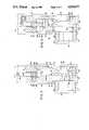
- FIG. 3is a section view, in side elevation, of the tip-lock shoe shown in FIGS. 1 and 2 in an unlocked, freely slidable condition;
- FIG. 4is a section view in side elevation, similar to FIG. 3, but wherein the tip-lock shoe is in a locked condition responsive to tilting of a window sash and the like;
- FIG. 5is a section view in side elevation, similar to FIG. 3, but wherein the tip-lock cam is partially cut-away and the tip-lock shoe is in a locked condition responsive to catastrophic failure of the counterbalance system.
- a fail-safe tip-lock shoeis shown in the drawings and generally designated by reference numeral 10.
- the tip-lock shoe 10comprises a hollow body or block 12 supported by a sash cord or cable 14 which is itself connected to a counterbalance system for a window sash or the like.
- the counterbalance systemitself does not form a part of the invention, and is not shown in the drawings.
- the tip-lock shoe 10is adapted to be slidably mounted in a channel formed by a track 8, partially illustrated in FIGS. 3, 4 and 5.
- a window sashis typically supported by two such shoes 10, running in respective vertically oriented tracks 8 disposed on opposite sides of a window frame. During normal operation, the shoes 10 are supported in the tracks by cords or cables 14, and in turn support an openable window sash in the window frame.
- the hollow body 12comprises a front wall 16, a left wall 18, a right wall 20, a top wall 22, a bottom wall 24 and a rear wall 28.
- a boss 26projects outwardly from the lower part of front wall 16.
- Boss 26defines a bore 30 for receiving rotatable cam member 90.
- Cam 90is provided with a slot 96, which in one rotational position is in alignment with and opens into notch 32.
- Front wall 16is also provided with an opening 34.
- Bottom wall 24is provided with two rectangular openings 36 and 38.
- Top wall 22is provided with a bore 40 and a cylindrical cavity 50 (See FIGS. 3, 4 and 5) in communication with one another. Cylindrical cavity 50 is of a larger diameter than bore 40.
- Rear wall 28is provided with an opening 48, bounded on either side by side walls 18 and 20, on the bottom by the floor or inside surface 56 of bottom 24 and by the lower edge 52 of wedge-shaped portion 42.
- a locking member 60is disposed in the body 10 and is movable between a retracted position enabling the body to slide freely in the track 8, as shown in FIG. 3, and an extended position for engaging the track 8 and preventing movement of the body in the track 8, as shown in FIGS. 4 and 5.
- the locking member 60comprises a plurality of working surfaces.
- Working surface 62is adapted to engage a wall of track 8, for locking the shoe into a fixed position in the track.
- Wedge-shaped surface 64is adapted to engage wedge-shaped portion 42 of rear wall 28.
- a notch or opening 66is bounded by a curved working surface 68.
- Downwardly depending legs 70 and 80are provided with wedge-shaped working surfaces 72 and 82 respectively.
- Legs 70 and 80are also provided with outwardly facing surfaces 74 and 84.
- An upstanding rib 76defines a notch 78.
- FIG. 3The retracted position of locking member 60 is illustrated in FIG. 3.
- the extended position of locking member 60for engaging the track 8 and preventing movement of the body in the track, is shown in FIGS. 4 and 5.
- the extended positionis to the right and higher than the retracted position.
- Upward movement of locking member 60causes a sliding engagement of wedge-shaped surfaces 42 and 64, which forces locking member 60 to the right, as it moves upwardly.
- Locking member 60may be forced upwardly, and to the right (outwardly, with respect the hollow body 10 and rear wall 28) responsive to either one of two lock activating members.
- a first lock activating member 90is in the form of a rotatable cam, which is disposed in bore 30 of boss 26.
- First lock activating member 90comprises a cylindrical body 92 an annular flange 94 and a projecting cam portion 98. Projecting cam portion 98 is provided with a cam surface 100.
- Cylindrical portion 92 and flange 94have a slot 96 formed therein, for receiving a corresponding lug which forms an interconnection between the tip-lock shoe 10 and an openable window sash or the like.
- the lugis insertable into notch 96 through notch 32. Thereafter, inwardly and outwardly tilting movements of the window sash effect rotation of the first lock activating member 90 within bore 30. In the unlocked condition shown in FIG.
- cam surface 100is out of contact with cam surface 68 of locking member 60.
- first lock activating member 90is rotated so as to bring cam surface 100 into engagement with cam surface 68, as shown in FIG. 4.
- Engagement of cam surface 100 and cam surface 68causes the locking member 60 to be forced upwardly.
- engagement of wedge-shaped working surfaces 42 and 64force the locking member outwardly, to the right, so that surface 62 engages track 8.
- the hollow bodyis thereby locked into position in track 8, so that the tip-lock shoe provides a safe and stable pivot point for the outwardly tilted window sash.
- first lock activating member 90When the window sash is tilted back into its normal operating position, first lock activating member 90 is rotated back into its initial position, so that cam surface 100 is no longer pressing upwardly against and engaging cam surface 68. Accordingly, lock member 60 is therefore free to fall downwardly and inwardly, back within the confines of the exterior boundaries of hollow body 12. The window sash is then free to be moved upwardly and downwardly as desired.
- a tip-lock shoe 10 according to this inventionis provided with an auxiliary trigger or mechanism for moving the locking member 60 from the retracted position to the extended position independently of the first lock activating member 90 and automatically responsive to a loss of counterbalance force, for example, if the sash cord or cable 14 snaps.
- auxiliary trigger or mechanismfor moving the locking member 60 from the retracted position to the extended position independently of the first lock activating member 90 and automatically responsive to a loss of counterbalance force, for example, if the sash cord or cable 14 snaps.
- Such failuremight also include failures in other parts of the counterbalance structure, for example pulleys, brackets, springs or the like.
- the auxiliary trigger or mechanismcomprises a second lock activating member 110 and a force transmission member 150.
- Second lock activating member 110has an inverted L-shape in side elevation.
- a base 112is provided with an upwardly opening slot 114 of substantially triangular cross-section. Groove 114 opens onto the edge of the distal end of base 112, as shown most clearly in FIG. 1.
- Two legs, 116 and 118are defined by a substantially semi-circular notch 124, and project downwardly from base 112.
- the distal ends of legs 116 and 118are provided with wedge-shaped working surfaces 120 and 122 respectively.
- Legs 116 and 118are adapted to extend downwardly on opposite sides of first lock activating member 90.
- the second lock activating member 110is mounted for slidable movement between a tip-lock shoe supporting position, as shown in FIG. 3, and a tip-lock shoe locking position, as shown in FIG. 5. As shown in FIG. 5, the ends of legs 116 and 118 extend into and through openings 36 and 38, in the bottom wall of hollow body 12, when the second lock activating member is in the shoe locking position. This provides sufficient travel for the second lock activating member without having to substantially increase the size of the tip-lock shoe 10, as compared to a conventional tip-lock shoe.
- the force transmission member 150rests on the inside surface or floor 56 of bottom wall 24.
- a notch 160defines two upward projections 146 and 148.
- Projection 146is provided with two rounded working surfaces 152 and 156.
- Projection 148is provided with two curved working surfaces 154 and 158.
- Notch 160accommodates first lock activating member 90, and serves to keep the force transmission member properly positioned.
- the force transmission member 150is operatively disposed between the second lock activating member 110 and the locking member 60. More particularly, wedge-shaped working surfaces 120 and 122 are adapted to engage curved working surfaces 152 and 154 respectively. Curved working surfaces 156 and 158 are adapted to operatively engage wedge-shaped working surfaces 72 and 82 respectively. As shown in FIG.
- the upper surface 108 of base 112engages the inner surface 106 of upper wall 22 of hollow body 12 in the shoe supporting position.
- second lock activating member 110moves downwardly into the shoe locking position, interengagement of working surfaces 120, 152 and 122, 154 pushes the force transmission member 150 to the right (in the sense of FIG. 5).
- Engagement of working surfaces 156, 72 and 158, 82forces the locking member upwardly.
- engagement of working surfaces 42 and 64moves locking member 60 outwardly as well, to engage the track 8 and lock the shoe 10 into position.
- Triangular shaped wall sections 44 and 46prevent the force transmission member 150 and the bottom of locking member 60 from falling out of the hollow body 12 when the hollow body is not disposed in the channel of track 8.
- Upstanding rib 76prevents the upper part of locking member 60 from falling out of opening 48 under the same circumstances.
- Notch 78provides clearance for the lower edge 52 of surface 42.
- the second lock activating member 110includes means for engaging the counterbalance system for supporting the body and the track and for urging the second lock activating member 110 from the shoe supporting position to the locking position independently of the first lock activating member and automatically responsive to a loss of counterbalance force, upon catastrophic failure of the counter balance system.
- the counterbalance systemis not directly connected to the hollow body 12, but is connected indirectly to the hollow body 12 and directly to the second lock activating member 110.
- a pin 126has and at least partially hollow body or barrel section 128 with a flange 130 at one end thereof and an opening 132 at the end thereof opposite the flange 130. Pin 126 is adapted to freely slidably pass through bore 50 and bore 40 in top wall 22, from the interior of hollow body 12 to the exterior thereof.
- Resilient means in the form of spring 134fits over pin 126, and in the shoe engaging position, fits substantially entirely in cylindrical cavity 50.
- the flange 130is adapted to be slidably received in groove 114, whereby spring 134 is kept in compression between the upper surface 108 of base 112 and the annular surface 54 formed at the top of cylindrical cavity 50, at the intersection of cavity 50 and bore 40.
- the end of sash cord or cable 14may be slipped into the opening 132 of pin 126, and held in place, for example by crimping or the like.
- second lock activating member 110will be held in firm engagement with the inner surface 106 of top wall 22, and the second lock activating member will remain in the shoe supporting position.
- the spring 134will axially expand, urging the second lock activating member 110 downwardly, into the shoe locking position.
- Downward movement of the second lock activating member 110effects movement of the force transmission member 150, which in turn effects movement of the locking member 60.
- this auxiliary locking mechanismhas been activated to prevent accidental movement of the window sash, the window sash may still be intentionally tilted out and removed to facilitate repairs.
- the spring 134should exert a predetermined force smaller in magnitude than the counterbalance force to enable normal operation when the counterbalance system is operating properly, but sufficient in magnitude to reliably move the locking member into the locking position, and thereafter hold the locking member in the locking position, when the counterbalance system fails.
- the amount of the predetermined forcewill depend upon the size and weight of the window sash, as well as the magnitude of the force exerted by the counterbalance system.
- All of the parts of a fail-safe tip-lock shoe 10 according to this inventionmay be manufactured from a variety of rigid plastic materials such as injection molded polymers, for example nylon, except of course for pin 126 and spring 134.
- the plastic materialsshould exhibit a coefficient of sliding friction which will enable easy movement of the shoe in the track, as well as easy engagement of the lock activating mechanisms.
Landscapes
- Engineering & Computer Science (AREA)
- Mechanical Engineering (AREA)
- Window Of Vehicle (AREA)
Abstract
Description
Claims (20)
Priority Applications (1)
| Application Number | Priority Date | Filing Date | Title |
|---|---|---|---|
| US07/257,742US4854077A (en) | 1988-10-13 | 1988-10-13 | Fail-safe tip-lock shoe |
Applications Claiming Priority (1)
| Application Number | Priority Date | Filing Date | Title |
|---|---|---|---|
| US07/257,742US4854077A (en) | 1988-10-13 | 1988-10-13 | Fail-safe tip-lock shoe |
Publications (1)
| Publication Number | Publication Date |
|---|---|
| US4854077Atrue US4854077A (en) | 1989-08-08 |
Family
ID=22977559
Family Applications (1)
| Application Number | Title | Priority Date | Filing Date |
|---|---|---|---|
| US07/257,742Expired - Fee RelatedUS4854077A (en) | 1988-10-13 | 1988-10-13 | Fail-safe tip-lock shoe |
Country Status (1)
| Country | Link |
|---|---|
| US (1) | US4854077A (en) |
Cited By (24)
| Publication number | Priority date | Publication date | Assignee | Title |
|---|---|---|---|---|
| US5077939A (en)* | 1990-11-27 | 1992-01-07 | Sealrite Windows, Inc. | Cam pivot for full tilt double-hung windows |
| US5383303A (en)* | 1991-12-04 | 1995-01-24 | Nakanishi Engineering Co., Ltd. | Window |
| US5542212A (en)* | 1995-04-14 | 1996-08-06 | Outlook Window Partnership L.P. | locking terminal for full tilt double-hung windows |
| US5632117A (en)* | 1995-01-13 | 1997-05-27 | Ashland Prod Inc | Sash balance brake assembly |
| US6032417A (en)* | 1997-04-11 | 2000-03-07 | Caldwell Manufacturing Company | Corner locking carrier shoe for tilt sash |
| US6119398A (en)* | 1998-11-05 | 2000-09-19 | Yates, Jr.; H. Dale | Tilt window balance shoe assembly with three directional locking |
| US6178695B1 (en)* | 1999-03-29 | 2001-01-30 | Carolina Builders, Inc. | Convertible window assembly |
| US6550184B1 (en) | 2001-02-09 | 2003-04-22 | Ashland Products, Inc. | Brake shoe for sash window or door assembly |
| US20040036300A1 (en)* | 2001-04-05 | 2004-02-26 | 420820 Ontario Limited | Combination cam lock/tilt latch and latching block therefor with added security feature |
| US20050055802A1 (en)* | 2000-11-09 | 2005-03-17 | Amesbury Springs Limited | Spring mounting for sash window tensioning arrangements |
| US6886295B2 (en) | 2002-02-01 | 2005-05-03 | Ashland Products, Inc. | Brake shoe with spring brake member |
| US20050193631A1 (en)* | 2004-03-08 | 2005-09-08 | Gary Marshik | Balance shoe for tilt-in window sashes |
| US20060230682A1 (en)* | 2005-04-14 | 2006-10-19 | S.I.L. Plastic Sales & Supplies Inc. | Sliding shoe for a window frame |
| US9133656B2 (en) | 2010-04-06 | 2015-09-15 | Amesbury Group, Inc. | Inverted constant force window balance for tilt sash |
| US9243435B1 (en)* | 2014-09-18 | 2016-01-26 | John Kaounas | Safety fall arrestor and wind lock for vertical lift doors |
| US9856112B1 (en)* | 2011-10-20 | 2018-01-02 | Anthony J. Cirone | Fall arresting system for vertically oriented belt driven linear actuators |
| WO2018022898A1 (en)* | 2016-07-28 | 2018-02-01 | Renlita Doors North America, Llc | Safety brake for vertical lifting doors |
| US10344514B2 (en) | 2001-01-12 | 2019-07-09 | Amesbury Group, Inc. | Snap lock balance shoe and system for a pivotable window |
| US10563440B2 (en) | 2017-04-07 | 2020-02-18 | Amesbury Group, Inc. | Inverted constant force window balance |
| US10563441B2 (en) | 2015-11-20 | 2020-02-18 | Amesbury Group, Inc. | Constant force window balance engagement system |
| US11193318B2 (en) | 2017-09-21 | 2021-12-07 | Amesbury Group, Inc. | Window balance shoes for a pivotable window |
| AU2017203444B2 (en)* | 2016-06-07 | 2022-03-17 | Monarch Group Pty Limited | A brake system |
| US11352821B2 (en) | 2019-01-09 | 2022-06-07 | Amesbury Group, Inc. | Inverted constant force window balance having slidable coil housing |
| US11560743B2 (en) | 2019-04-02 | 2023-01-24 | Amesbury Group, Inc. | Window balance systems |
Citations (4)
| Publication number | Priority date | Publication date | Assignee | Title |
|---|---|---|---|---|
| US3797168A (en)* | 1971-10-21 | 1974-03-19 | D Trout | Automatically-locking positively-unlocked sash balance |
| US4068406A (en)* | 1976-08-19 | 1978-01-17 | Jim Walter Corporation | Side camming balance spring lock |
| US4590708A (en)* | 1985-03-01 | 1986-05-27 | Allen-Stevens Corp. | Arrangement for tiltably mounting a window sash |
| US4696375A (en)* | 1986-06-16 | 1987-09-29 | Harris Preble Company | Chain break safety device |
- 1988
- 1988-10-13USUS07/257,742patent/US4854077A/ennot_activeExpired - Fee Related
Patent Citations (4)
| Publication number | Priority date | Publication date | Assignee | Title |
|---|---|---|---|---|
| US3797168A (en)* | 1971-10-21 | 1974-03-19 | D Trout | Automatically-locking positively-unlocked sash balance |
| US4068406A (en)* | 1976-08-19 | 1978-01-17 | Jim Walter Corporation | Side camming balance spring lock |
| US4590708A (en)* | 1985-03-01 | 1986-05-27 | Allen-Stevens Corp. | Arrangement for tiltably mounting a window sash |
| US4696375A (en)* | 1986-06-16 | 1987-09-29 | Harris Preble Company | Chain break safety device |
Cited By (40)
| Publication number | Priority date | Publication date | Assignee | Title |
|---|---|---|---|---|
| US5077939A (en)* | 1990-11-27 | 1992-01-07 | Sealrite Windows, Inc. | Cam pivot for full tilt double-hung windows |
| US5383303A (en)* | 1991-12-04 | 1995-01-24 | Nakanishi Engineering Co., Ltd. | Window |
| US5632117A (en)* | 1995-01-13 | 1997-05-27 | Ashland Prod Inc | Sash balance brake assembly |
| US5806243A (en)* | 1995-01-13 | 1998-09-15 | Ashland Products, Inc. | Sash balance brake assembly |
| US5542212A (en)* | 1995-04-14 | 1996-08-06 | Outlook Window Partnership L.P. | locking terminal for full tilt double-hung windows |
| US6032417A (en)* | 1997-04-11 | 2000-03-07 | Caldwell Manufacturing Company | Corner locking carrier shoe for tilt sash |
| US6119398A (en)* | 1998-11-05 | 2000-09-19 | Yates, Jr.; H. Dale | Tilt window balance shoe assembly with three directional locking |
| US6178695B1 (en)* | 1999-03-29 | 2001-01-30 | Carolina Builders, Inc. | Convertible window assembly |
| US20050055802A1 (en)* | 2000-11-09 | 2005-03-17 | Amesbury Springs Limited | Spring mounting for sash window tensioning arrangements |
| US7552510B2 (en) | 2000-11-09 | 2009-06-30 | Amesbury Springs Limited | Spring mounting for sash window tensioning arrangements |
| US7076835B2 (en)* | 2000-11-09 | 2006-07-18 | Amesbury Springs Limited | Spring mounting for sash window tensioning arrangements |
| US20070011846A1 (en)* | 2000-11-09 | 2007-01-18 | Amesbury Springs Limited | Spring mounting for sash window tensioning arrangements |
| US10533359B2 (en) | 2001-01-12 | 2020-01-14 | Amesbury Group, Inc. | Method of assembling a window balance system |
| US10344514B2 (en) | 2001-01-12 | 2019-07-09 | Amesbury Group, Inc. | Snap lock balance shoe and system for a pivotable window |
| US20070151157A1 (en)* | 2001-02-09 | 2007-07-05 | Newell Operating Company | Brake Shoe For Sash Window Or Door Assembly |
| US6550184B1 (en) | 2001-02-09 | 2003-04-22 | Ashland Products, Inc. | Brake shoe for sash window or door assembly |
| US20050183340A1 (en)* | 2001-02-09 | 2005-08-25 | O'donnell Richard H. | Brake shoe for sash window or door assembly |
| US7194839B2 (en) | 2001-02-09 | 2007-03-27 | Newell Operating Company | Brake shoe for sash window or door assembly |
| US6915609B2 (en) | 2001-02-09 | 2005-07-12 | Ashland Products, Inc. | Brake shoe for sash window or door assembly |
| US20040036300A1 (en)* | 2001-04-05 | 2004-02-26 | 420820 Ontario Limited | Combination cam lock/tilt latch and latching block therefor with added security feature |
| US7147255B2 (en)* | 2001-04-05 | 2006-12-12 | 420820 Ontario Limited | Combination cam lock/tilt latch and latching block therefor with added security feature |
| US6886295B2 (en) | 2002-02-01 | 2005-05-03 | Ashland Products, Inc. | Brake shoe with spring brake member |
| US20050193631A1 (en)* | 2004-03-08 | 2005-09-08 | Gary Marshik | Balance shoe for tilt-in window sashes |
| US7726073B2 (en)* | 2005-04-14 | 2010-06-01 | S.I.L. Plastic Sales & Supplies Inc. | Sliding shoe for a window frame |
| US20060230682A1 (en)* | 2005-04-14 | 2006-10-19 | S.I.L. Plastic Sales & Supplies Inc. | Sliding shoe for a window frame |
| US9133656B2 (en) | 2010-04-06 | 2015-09-15 | Amesbury Group, Inc. | Inverted constant force window balance for tilt sash |
| US9856112B1 (en)* | 2011-10-20 | 2018-01-02 | Anthony J. Cirone | Fall arresting system for vertically oriented belt driven linear actuators |
| US9243435B1 (en)* | 2014-09-18 | 2016-01-26 | John Kaounas | Safety fall arrestor and wind lock for vertical lift doors |
| US10563441B2 (en) | 2015-11-20 | 2020-02-18 | Amesbury Group, Inc. | Constant force window balance engagement system |
| AU2017203444B2 (en)* | 2016-06-07 | 2022-03-17 | Monarch Group Pty Limited | A brake system |
| WO2018022898A1 (en)* | 2016-07-28 | 2018-02-01 | Renlita Doors North America, Llc | Safety brake for vertical lifting doors |
| US11346140B2 (en) | 2016-07-28 | 2022-05-31 | Renlita Doors North America, Llc | Safety brake for vertical lifting doors |
| US11136801B2 (en) | 2017-04-07 | 2021-10-05 | Amesbury Group, Inc. | Inverted constant force window balance |
| US10563440B2 (en) | 2017-04-07 | 2020-02-18 | Amesbury Group, Inc. | Inverted constant force window balance |
| US11193318B2 (en) | 2017-09-21 | 2021-12-07 | Amesbury Group, Inc. | Window balance shoes for a pivotable window |
| US12091895B2 (en) | 2017-09-21 | 2024-09-17 | Amesbury Group, Inc. | Window balance shoes for a pivotable window |
| US12410648B2 (en) | 2017-09-21 | 2025-09-09 | Amesbury Group, Inc. | Window balance shoes for a pivotable window |
| US11352821B2 (en) | 2019-01-09 | 2022-06-07 | Amesbury Group, Inc. | Inverted constant force window balance having slidable coil housing |
| US11560743B2 (en) | 2019-04-02 | 2023-01-24 | Amesbury Group, Inc. | Window balance systems |
| US12091894B2 (en) | 2019-04-02 | 2024-09-17 | Amesbury Group, Inc. | Window balance systems |
Similar Documents
| Publication | Publication Date | Title |
|---|---|---|
| US4854077A (en) | Fail-safe tip-lock shoe | |
| US4452012A (en) | Pivot shoe for sash balance | |
| US6119398A (en) | Tilt window balance shoe assembly with three directional locking | |
| CA2075321C (en) | Window | |
| AU639631B2 (en) | A window operator and hinge structure | |
| US4922657A (en) | Locking slide for tilt-out window balance system | |
| US5090750A (en) | Locking mechanism for sash type windows | |
| US5544450A (en) | Double-hung tilting sash type window system | |
| US5301989A (en) | Tilt lock for double-hung windows | |
| EP0400534B1 (en) | Device for the shutter-like and tilt-down opening of a window or door-window | |
| US5127192A (en) | Pivot shoe for removable sash | |
| AU738182B2 (en) | Improvements in or relating to hinges | |
| US6041475A (en) | Locking counterbalance shoe for tiltably removable sash windows | |
| US5189838A (en) | Tilt sash lock shoe system | |
| US5076018A (en) | Device for easily assembling and disassembling slidable doors to and from pieces of furniture | |
| US20050091791A1 (en) | Counterbalance system for a tilt-in window having an improved shoe assembly and anchor mount | |
| CA2303055C (en) | Improved hinge for furniture and the like, with movable arm arranged inside the fixed arm | |
| CA2232700C (en) | Sash brake for double hung window with pivoting sash | |
| CA2188821A1 (en) | Window tilt lock and frictional positioner shoe | |
| EP0864719B1 (en) | System for opening and closing doors in furniture, rooms and the like | |
| CA2323280A1 (en) | A window panel balance apparatus and method | |
| CA2337931A1 (en) | Guide assembly for a tilt-out sash window | |
| US3233657A (en) | Folding door assembly and mounting units therefor | |
| JP2903281B2 (en) | Fully open door | |
| US3688441A (en) | Takeout mechanism for sash type single hung windows |
Legal Events
| Date | Code | Title | Description |
|---|---|---|---|
| AS | Assignment | Owner name:SCHLEGEL CORPORATION, 400 EAST AVE., ROCHESTER, NY Free format text:ASSIGNMENT OF ASSIGNORS INTEREST.;ASSIGNORS:ROGERS, TRACY G.;MORAN, JOHN;REEL/FRAME:004954/0878 Effective date:19881024 Owner name:SCHLEGEL CORPORATION, 400 EAST AVE., ROCHESTER, NY Free format text:ASSIGNMENT OF ASSIGNORS INTEREST;ASSIGNORS:ROGERS, TRACY G.;MORAN, JOHN;REEL/FRAME:004954/0878 Effective date:19881024 | |
| FEPP | Fee payment procedure | Free format text:PAYOR NUMBER ASSIGNED (ORIGINAL EVENT CODE: ASPN); ENTITY STATUS OF PATENT OWNER: LARGE ENTITY | |
| FPAY | Fee payment | Year of fee payment:4 | |
| FPAY | Fee payment | Year of fee payment:8 | |
| AS | Assignment | Owner name:FUJI BANK, LIMITED, THE, AS SECURITY AGENT, NEW YO Free format text:SECURITY AGREEMENT;ASSIGNOR:SCHLEGEL SYSTEMS, INC.;REEL/FRAME:008855/0830 Effective date:19971209 Owner name:SCHLEGEL SYSTEMS INC., NEW YORK Free format text:ASSIGNMENT OF ASSIGNORS INTEREST;ASSIGNORS:SCHLEGEL GMBH;SCHLEGEL CORPORATION;SCHLEGEL S.A.;AND OTHERS;REEL/FRAME:008842/0773 Effective date:19971212 | |
| REMI | Maintenance fee reminder mailed | ||
| LAPS | Lapse for failure to pay maintenance fees | ||
| FP | Lapsed due to failure to pay maintenance fee | Effective date:20010808 | |
| STCH | Information on status: patent discontinuation | Free format text:PATENT EXPIRED DUE TO NONPAYMENT OF MAINTENANCE FEES UNDER 37 CFR 1.362 |