US4853811A - Magnetic disk drive with low profile head-suspension system - Google Patents
Magnetic disk drive with low profile head-suspension systemDownload PDFInfo
- Publication number
- US4853811A US4853811AUS07/081,204US8120487AUS4853811AUS 4853811 AUS4853811 AUS 4853811AUS 8120487 AUS8120487 AUS 8120487AUS 4853811 AUS4853811 AUS 4853811A
- Authority
- US
- United States
- Prior art keywords
- slider
- magnetic
- load beam
- media
- height
- Prior art date
- Legal status (The legal status is an assumption and is not a legal conclusion. Google has not performed a legal analysis and makes no representation as to the accuracy of the status listed.)
- Expired - Lifetime
Links
Images


Classifications
- G—PHYSICS
- G11—INFORMATION STORAGE
- G11B—INFORMATION STORAGE BASED ON RELATIVE MOVEMENT BETWEEN RECORD CARRIER AND TRANSDUCER
- G11B5/00—Recording by magnetisation or demagnetisation of a record carrier; Reproducing by magnetic means; Record carriers therefor
- G11B5/48—Disposition or mounting of heads or head supports relative to record carriers ; arrangements of heads, e.g. for scanning the record carrier to increase the relative speed
- G11B5/58—Disposition or mounting of heads or head supports relative to record carriers ; arrangements of heads, e.g. for scanning the record carrier to increase the relative speed with provision for moving the head for the purpose of maintaining alignment of the head relative to the record carrier during transducing operation, e.g. to compensate for surface irregularities of the latter or for track following
- G11B5/60—Fluid-dynamic spacing of heads from record-carriers
- G11B5/6005—Specially adapted for spacing from a rotating disc using a fluid cushion
- G—PHYSICS
- G11—INFORMATION STORAGE
- G11B—INFORMATION STORAGE BASED ON RELATIVE MOVEMENT BETWEEN RECORD CARRIER AND TRANSDUCER
- G11B5/00—Recording by magnetisation or demagnetisation of a record carrier; Reproducing by magnetic means; Record carriers therefor
- G11B5/48—Disposition or mounting of heads or head supports relative to record carriers ; arrangements of heads, e.g. for scanning the record carrier to increase the relative speed
- G11B5/4806—Disposition or mounting of heads or head supports relative to record carriers ; arrangements of heads, e.g. for scanning the record carrier to increase the relative speed specially adapted for disk drive assemblies, e.g. assembly prior to operation, hard or flexible disk drives
- G11B5/4826—Mounting, aligning or attachment of the transducer head relative to the arm assembly, e.g. slider holding members, gimbals, adhesive
- G—PHYSICS
- G11—INFORMATION STORAGE
- G11B—INFORMATION STORAGE BASED ON RELATIVE MOVEMENT BETWEEN RECORD CARRIER AND TRANSDUCER
- G11B5/00—Recording by magnetisation or demagnetisation of a record carrier; Reproducing by magnetic means; Record carriers therefor
- G11B5/48—Disposition or mounting of heads or head supports relative to record carriers ; arrangements of heads, e.g. for scanning the record carrier to increase the relative speed
- G11B5/4806—Disposition or mounting of heads or head supports relative to record carriers ; arrangements of heads, e.g. for scanning the record carrier to increase the relative speed specially adapted for disk drive assemblies, e.g. assembly prior to operation, hard or flexible disk drives
- G11B5/4833—Structure of the arm assembly, e.g. load beams, flexures, parts of the arm adapted for controlling vertical force on the head
Definitions
- This inventionpertains to magnetic disk drives and more particularly to disk drives with low profile transducer head-suspension assemblies which cooperate with closely spaced magnetic disk storage media.
- the requirement for progressively higher magnetic disk drive storage capacitiesis met through the use of increased linear bit densities, increased track densities and by increasing the number of recording surfaces.
- the single constraint that remains unalteredis the overall size of the drive.
- the overall dimensions of the drive unit or the form factoris the standard that must be accommodated to make the drive a commercially acceptable product.
- the existing head and suspension designsare adequate. As increased numbers of disks are used to achieve more disk surfaces within the same dimensions or form factor, the space between adjacent disks is reduced, making more difficult both the assembly and operation of the device. Two major problems arise, one is the height limitation and the other is the less than adequate dynamic response of existing suspension designs in the closely spaced disk environment.
- One way to accommodate close spacing between disk surfacesis to offset head assemblies rather than use back to back mounting so that in the side by side arrangement each head and associated suspension can utilize the full height separating adjacent disks.
- the head-suspension assemblyis shown in the environment of an inline transducer suspension mounted on a rotary actuator.
- the sliderhas a full height portion to provide the maximum height for the coil and core portions of the transducer and a reduced height forward portion that accommodates the gimbal spring-load beam structure of the associated suspension without exceeding the vertical dimension of the full height portion.
- the window size in the corecan thus receive 25 turns of 45 gauge bifilar wire and still achieve a slider height of less than 1.5 millimeters.
- the disclosed slider or head design as shown, in combination with a suspension contained within the height of the headallows the head-suspension assembly to obtain an overall height in an inline configuration of less than 1.5 millimeters.
- the full height rear portionhas a maximum height which does not exceed 1.4 millimeters and the reduced height forward portion has a height of 0.65 millimeters. This is a reduction of about 35% from the current state of the art designs.
- the reduced height portionalso lowers the mass of the slider which raises the resonant frequencies of the head suspension system and moves such frequencies away from the lower frequencies generated by the mechanical elements of the file.
- the lower massalso improves access time, the reduced amount of ferrite reduces magnetic noise pickup and the head center of mass and the load point of the suspension are lowered, both of which contribute to increasing the dynamic stability of the head suspension assembly.
- Other magnetic properties of the headare not compromised by the reduced mass design and the heads can be manufactured using current processes and equipment.
- the load beamwith a flexible gram form and a load carrying portion, is formed as a single part with the stiffened substantially rigid load carrying portion attached to the gimbal spring.
- the gimbal springis connected to both the load beam and the slider to provide the support for the magnetic transducer as a part of the actuator assembly.
- the load carrying portionis afforded rigidity by turning the tapered margins to not only provide rigidity, but also create a lead channel to receive and support the snare through which passes the conductors from the transducer coil.
- the lead channelsnot only provide a convenient route to contain the head leads within a minimum height, but further protect the head leads against mechanical damage during manufacture and afford protection against electrical noise interference by providing a grounded three quarter enclosure along much of the lead length.
- flexureis afforded by a flat portion of increasing width that has stiffness controlled by the material, thickness, length and the size of a central aperture which enhances lateral stiffness.
- the reduced length of this suspension designoffers better space utilization in compact files.
- the high lateral stiffnessallows high access rates without suspension windup or suspension roll of the slider. This attribute enables maximum acceleration during seek operations and minimizes settle time after reaching the desired track, both of which functions contribute to improved access time.
- File storage capacityis increased using the suspension since the lack of resonance of the suspension requires less disk area be used for crash stopping.
- suspension designis shown in the environment of an inline transducer head suspension and optimized to a particular set of parameters, the performance advantages could also be used in an orthogonal head-suspension assembly.
- the techniquecould be extended by further shortening overall suspension length to increase resonant frequencies for optimum performance in a particular environment and the length and width of the formed area can be changed to tailor the stiffness to the required value.
- Constrained layer dampingcan be added to portions of the formed area and/or load beam to further enhance the dynamics of the design beyond what is possible with the all metal design shown.
- a viscoelastic materialsuch as RTV silicone rubber can be applied to the load dimple for applications where extremely high accelerations without hysteresis are needed.
- FIG. 1is an exploded view of the head-suspension assembly of the present invention.
- FIGS. 2 and 3are respectively elevation and bottom views of the slider assembly of the invention.
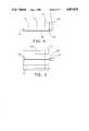
- FIGS. 4 and 5are respectively bottom and side elevation views of a state of the art head-suspension assembly in an inline configuration.
- FIG. 6is a graph showing resonance gain of the head-suspension of FIGS. 4 and 5 due to lateral input.
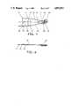
- FIGS. 7 and 8are respectively plan and side elevation views of the head-suspension assembly of the present invention.
- FIG. 9is a graph, similar to that of FIG. 6, showing the resonance gain of the head-suspension assembly of FIGS. 7 and 8.
- FIG. 10is an isometric view of a disk drive with the cover removed and using the present head-suspension assemblies in conjunction with a rotary actuator and an eight disk spindle assembly.
- the head-suspension assemblyis shown in the exploded view of FIG. 1.
- the head assemblyincludes a halfback slider 12 (also shown in FIGS. 2 and 3) which has a full height rear portion 13 and a reduced height forward portion 14 that presents a planar shelf 15 surface to which the gimbal 17 spring is bonded.
- the full height portion 13 of the sliderincludes the magnetic core portions including the C-core 19 that creates the window 20 through which the windings 21 are received about the bobbin 22.
- the C-core 19is intimately bonded to the slider body at the upper side of the window 20 and is bonded by the glass filled gap 23 in the conventional manner to create a minimum length transducer gap immediately adjacent the magnetic media recording surface.
- the headis of the three rail type with the outer rails 25 presenting the principal air bearing surfaces that in the operative assembled condition support the head above the adjacent media.
- the read-write transducer gapis formed at the rear of the center rail 26.
- the reduced height portion 14extends well to the rear of the location axially overlying the center of the air bearing surface and the center of mass of the slider.
- the full height portion 13accommodates the coil windings 21 and the reduced height portion enables the gimballed suspension to be connected without exceeding the full height dimension. With these constraints it is possible to design and manufacture a transducer head assembly less than 1.5 millimeters in height.
- the reduced height portion 14is less than half the height of the full height portion 13 to create a low mass head.
- the reduced mass of the headraises the resonant frequencies of the head-suspension assembly and also improves the access time.
- the smaller quantity of ferrite in the headreduces the magnetic core noise pickup.
- the resonances of this reduced size and mass head-suspension systemare at a frequency above the file resonances to enable superior dynamic performance in a fast access magnetic disk storage system.
- the gram form and load carrying elements of the load beamare formed as a single part 30 from resilient metal sheet material.
- the margins 31are debossed and turned upward to form channels 32,33 and channel crimp tabs 34 with the distal end terminating in an outboard crimp tab 35.
- the forward portionis not only stiffened or rigidified by the formed channels 32,33 and the working of the metal, but in addition receives the snare 37 which encloses the leads 38 from the transducer coil windings 21.
- the snare 37is retained by the crimp tabs 34,35.
- the channel 32 or 33in addition to providing mechanical protection, affords a grounded electrical shield which approximately three quarters surrounds the snare 37 throughout a substantial portion of its length.
- the symmetrical channel structures 32,33 at each sidepermit a common part to be used for both upwardly and downwardly facing transducer head assemblies.
- the gram form portion of the suspensionis in the form of two legs 40 separated by a window opening 41 and with a longitudinal extent from the rear of the channels 32,33 to the laser weld locations 43 which attach the flexure to the mounting plate 45.
- the permanent set applied by bending the gram form legs 40determines the gram load force which urges the slider toward the confronting media surface A total of seven laser welds 43,44 secure the load beam 30 to mounting plate 45.
- Additional crimp tabs 46are used to position and secure the snare 37 as it reaches the actuator arm beyond the flexure portion of the suspension.
- the rearward opening 48 in the load beam 30 and the tooling slot 49 in the mount plate 45serve to correctly align the parts during fabrication of the suspension assembly.
- Mount plate 45is also provided with an orientation feature 50 for use when automatically attaching the load beam to the mount plate 45.
- the weld pockets 51are of reduced material thickness to provide the welding sites for attachment of the head-suspension assembly to the actuator arm.
- a gimbal spring 17serves to connect the transducer head 11 to the load beam 30 and is designed to accommodate pitch and roll movements of the transducer head 11.
- Gimbal spring 17is formed of a single piece of resilient sheet metal material and is coplanar except for the raised tab portion 53 that is bonded to the shelf surface or upper surface 15 of the slider 12 reduced height portion 14.
- a load dome 55is a substantially spherical debossment that extends to the lower surface of the coplanar portion.
- the gimbal spring 17is laser welded at four locations 57 to the load beam portion of the load beam member 30. Tooling holes 58,59 assist in aligning the load beam-flexure 30 and gimbal spring 17 during the welding of the parts to one another.
- load dome 55maintains essentially point contact with the load beam surface while the curved flexure portions 68 of gimbal spring 17 permit the pitch and roll motions of the head 11.
- FIGS. 4 and 5illustrate a state of the art head-suspension assembly 63 in an inline configuration with a single load path that is advantageous in minimizing the number of resonances in the servo bandwidths to allow faster access times and more stringent servo control.
- the load beam-flexure 64is welded at locations 65 to a mounting plate 66.
- the load beam portionis stiffened by marginal flanges 67 and a flat back slider 68 is bonded to gimbal spring 69 which is welded to the load beam portion at locations 70.
- the magnetic transducer gap 71is formed using a C-core 72 at the trailing edge of the center rail 73.
- the transducer coil leads 74pass through a snare 75 that is retained along the center of the lower surface of the load beam portion (as seen in FIG. 4) and is retained by crimp tabs 76 and pickle forks 77.
- the graph of FIG. 6shows a typical mechanical gain of the head-suspension assembly of FIGS. 4 and 5 that has been experimentally determined.
- FIGS. 7 and 8show the head-suspension assembly of FIG. 1 in assembled form.
- the plan view of FIG. 7shows the load beam-flexure 30 welded to mount block 45 and the gimbal spring 17 which is welded to the load beam portion and bonded to the halfback slider 12.
- the coil leads 38pass through the tubular snare 37, with the snare being retained by the terminal crimp tab 35, the channel crimp tabs which are not visible and the crimp tabs 46 formed in the load beam and adjoining mount block 45.
- FIG. 9illustrates a transfer function that has been achieved using the design of FIGS. 7 and 8.
- the mechanical gainis constrained within allowed limits such that the transfer function shows no severe resonance conditions at the lower frequencies that would require additional damping materials.
- the frequency increase of the conditions of resonanceallows more servo bandwidth and increased file storage capacity.
- the head-suspension of FIGS. 7 and 8, using the flexure legs 40 and intervening window 41maintains a higher lateral stiffness to enable higher access rates by tolerating maximum initial acceleration and having a shorter settle time at the addressed track location.
- FIG. 10shows a disk file with the head-disk assembly cover removed and a rotary actuator 81 that supports and moves transducer heads 82 from one concentric data track to another using inline suspensions 83.
- the spindle assembly 84includes eight magnetic storage disks 85.
- the present head-suspension designprovides a maximum overall height that does not exceed the full height portion of the transducer head by using a halfback slider design that enables the suspension to attach to the upper surface or shelf of the reduced height portion of the halfback slider. This overcomes the space constraints dictated by closely spaced disks. In addition the design enhances the lateral stiffness of the suspension, both factors improving the dynamic response of the system.
- the advantages of the present head-suspension assemblyare obtained using an all metal suspension without increasing manufacturing cost or requiring new or more expensive manufacturing techniques or equipment.
- the head-suspension assembly design as shown and describedmakes possible a profile height of less than 1.5 millimeters while increasing resonance frequencies above file resonance frequencies and achieving superior dynamic performance in a fast access device. Further, these benefits have been achieved without impairing or compromising other magnetic or mechanical properties of the head or suspension.
- the inventioncould also be utilized to obtain the advantages in an orthogonal suspension.
Landscapes
- Supporting Of Heads In Record-Carrier Devices (AREA)
- Adjustment Of The Magnetic Head Position Track Following On Tapes (AREA)
Abstract
Description
Claims (18)
Priority Applications (6)
| Application Number | Priority Date | Filing Date | Title |
|---|---|---|---|
| US07/081,204US4853811A (en) | 1987-08-03 | 1987-08-03 | Magnetic disk drive with low profile head-suspension system |
| JP63161084AJPH071616B2 (en) | 1987-08-03 | 1988-06-30 | Magnetic head mechanism |
| CA000571468ACA1308807C (en) | 1987-08-03 | 1988-07-07 | Magnetic disk drive with low profile head-suspension system |
| EP88306536AEP0302615B1 (en) | 1987-08-03 | 1988-07-18 | A head suspension assembly for a magnetic record disk store |
| DE8888306536TDE3875022T2 (en) | 1987-08-03 | 1988-07-18 | HEAD SUSPENSION ARRANGEMENT FOR A MAGNETIC RECORDING PLATE STACK. |
| SG147994ASG147994G (en) | 1987-08-03 | 1994-10-13 | A head suspension assembly for a magnetic record disk store |
Applications Claiming Priority (2)
| Application Number | Priority Date | Filing Date | Title |
|---|---|---|---|
| US07/081,204US4853811A (en) | 1987-08-03 | 1987-08-03 | Magnetic disk drive with low profile head-suspension system |
| SG147994ASG147994G (en) | 1987-08-03 | 1994-10-13 | A head suspension assembly for a magnetic record disk store |
Publications (1)
| Publication Number | Publication Date |
|---|---|
| US4853811Atrue US4853811A (en) | 1989-08-01 |
Family
ID=26664419
Family Applications (1)
| Application Number | Title | Priority Date | Filing Date |
|---|---|---|---|
| US07/081,204Expired - LifetimeUS4853811A (en) | 1987-08-03 | 1987-08-03 | Magnetic disk drive with low profile head-suspension system |
Country Status (6)
| Country | Link |
|---|---|
| US (1) | US4853811A (en) |
| EP (1) | EP0302615B1 (en) |
| JP (1) | JPH071616B2 (en) |
| CA (1) | CA1308807C (en) |
| DE (1) | DE3875022T2 (en) |
| SG (1) | SG147994G (en) |
Cited By (63)
| Publication number | Priority date | Publication date | Assignee | Title |
|---|---|---|---|---|
| US5012368A (en)* | 1988-04-29 | 1991-04-30 | International Business Machines Corporation | Magnetic head/support assembly and access mechanism for a disk file |
| US5027241A (en)* | 1989-06-01 | 1991-06-25 | Quantum Corporation | Data head load beam for height compacted, low power fixed head and disk assembly |
| US5027239A (en)* | 1989-12-22 | 1991-06-25 | Seagate Technology, Inc. | Routing a sleeve and conductors in a head-gimbal assembly |
| US5027240A (en)* | 1989-03-27 | 1991-06-25 | Computer & Communications Technology Corp. | Disk head assembly load beam |
| US5053904A (en)* | 1989-04-03 | 1991-10-01 | Alps Electric Co., Ltd. | Hard disk driving device having a plurality of head sliders with equalized flotation height |
| US5077713A (en)* | 1989-12-13 | 1991-12-31 | Matsushita Electric Industrial Co., Ltd. | Magneto-optical disk writing/reading apparatus including a floating magnetic head |
| US5081553A (en)* | 1988-03-31 | 1992-01-14 | Applied Magnetics Corporation | Combination of elongated load arm and microminimonolithic head slider |
| US5095396A (en)* | 1990-08-20 | 1992-03-10 | Seagate Technology, Inc. | Unitary E-block assembly for use in a disk drive |
| WO1992009076A1 (en)* | 1990-11-09 | 1992-05-29 | Hutchinson Technology, Inc. | Improved magnetic head suspension |
| US5122998A (en)* | 1989-06-15 | 1992-06-16 | Matsushita Electric Industrial Co., Ltd. | Magneto-optical recording and reproducing apparatus having magnetic head vertically moving support |
| US5124865A (en)* | 1988-03-31 | 1992-06-23 | Applied Magnetics Corporation | Microminimonolithic magnetic head slider having vertically extending slots to reduce flux leakage losses |
| US5161074A (en)* | 1990-12-21 | 1992-11-03 | Seagate Technology, Inc. | Flexible retainer for cantilevered matrix board |
| US5203454A (en)* | 1990-10-25 | 1993-04-20 | Strong Leslie G | Method and apparatus for transporting sensitive electronic components |
| US5208712A (en)* | 1989-06-01 | 1993-05-04 | Quantum Corporation | Data head load beam for height compacted, low power fixed head and disk assembly |
| US5218497A (en)* | 1988-12-02 | 1993-06-08 | Hitachi, Ltd. | Magnetic recording-reproducing apparatus and magnetoresistive head having two or more magnetoresistive films for use therewith |
| WO1993015593A1 (en)* | 1992-01-28 | 1993-08-05 | Hutchinson Technology Incorporated | Carrier strip head interconnect assembly |
| US5282103A (en)* | 1992-10-07 | 1994-01-25 | Read-Rite Corporation | Magnetic head suspension assembly fabricated with integral load beam and flexure |
| US5299080A (en)* | 1989-12-27 | 1994-03-29 | Matsushita Electric Industrial Co., Ltd. | Floating head slider with improved suspension for use in magnetic/optical disk recording apparatuses |
| US5313332A (en)* | 1990-11-16 | 1994-05-17 | Applied Magnetics Corporation | Flexure suspension for two axis actuator |
| US5331489A (en)* | 1992-11-12 | 1994-07-19 | Seagate Technology, Inc. | Gimbal for a flexure for top-terminated heads |
| US5381288A (en)* | 1992-06-16 | 1995-01-10 | Applied Magnetics Corporation, Inc. | Center moment suspension assembly |
| US5391842A (en)* | 1991-12-16 | 1995-02-21 | Hutchinson Technology, Inc. | Carrier strip head interconnect assembly |
| US5407068A (en)* | 1991-10-22 | 1995-04-18 | Strong; Leslie G. | Method and apparatus for transporting test boards |
| US5408372A (en)* | 1990-09-07 | 1995-04-18 | Karam, Ii; Raymond M. | Transducer suspension damping via microstiffening |
| US5446611A (en)* | 1990-09-14 | 1995-08-29 | Hutchinson Technology, Inc. | Head suspension assembly which includes a load beam element having relief channels |
| US5461525A (en)* | 1990-09-14 | 1995-10-24 | Hutchinson Technology Incorporated | Load beam having areas of varying thickness in the spring region formed by varying numbers of lamina |
| US5491597A (en)* | 1994-04-15 | 1996-02-13 | Hutchinson Technology Incorporated | Gimbal flexure and electrical interconnect assembly |
| US5570261A (en)* | 1993-09-16 | 1996-10-29 | International Business Machines Corporation | Transducer suspension system |
| US5598307A (en)* | 1994-04-15 | 1997-01-28 | Hutchinson Technology Inc. | Integrated gimbal suspension assembly |
| US5719727A (en)* | 1993-01-07 | 1998-02-17 | Hutchinson Technology Incorporated | Interior stiffening and head lifter rails |
| US5729511A (en) | 1991-02-15 | 1998-03-17 | Discovision Associates | Optical disc system having servo motor and servo error detection assembly operated relative to monitored quad sum signal |
| US5748578A (en) | 1995-01-25 | 1998-05-05 | Discovision Associates | Colpitts type oscillator having reduced ringing and improved optical disc system utilizing same |
| US5808836A (en)* | 1995-08-30 | 1998-09-15 | International Business Machines Corporation | Load beam with grooved wire-gluing region |
| US5808980A (en) | 1991-02-15 | 1998-09-15 | Discovision Associates | Seek actuator for optical recording |
| US5815348A (en)* | 1995-12-15 | 1998-09-29 | Hutchinson Technology Incorporated | Load beam with inward stiffening channel |
| US5835306A (en)* | 1995-06-07 | 1998-11-10 | Hutchinson Technology Incorporated | Integrated gimbal suspension assembly with assymetric bond pad |
| US5839193A (en)* | 1994-04-15 | 1998-11-24 | Hutchinson Technology Incorporated | Method of making laminated structures for a disk drive suspension assembly |
| US5877919A (en)* | 1996-06-07 | 1999-03-02 | Western Digital Corporation | Method and apparatus for a low-profile head-suspension attachment for a disk drive |
| US5920539A (en) | 1995-01-25 | 1999-07-06 | Discovision Associates | Apparatus and method for suppression of electromagnetic emissions having a groove on an external surface for passing an electrical conductor |
| US5974007A (en) | 1995-01-25 | 1999-10-26 | Discovision Associates | Apparatus for moving a carriage assembly from an initial position to a target position |
| US5995330A (en)* | 1990-12-19 | 1999-11-30 | Mobile Storage Technology Inc. | Rigid disk drive with dynamic head loading apparatus |
| US6011671A (en)* | 1997-04-10 | 2000-01-04 | Seagate Technology, Inc. | Head gimbal assembly for limiting dimple separation for a data storage device |
| US6069857A (en) | 1991-02-15 | 2000-05-30 | Discovision Associates | Optical disc system having improved circuitry for performing blank sector check on readable disc |
| US6091684A (en) | 1995-01-25 | 2000-07-18 | Discovision Associates | Optical disc system and method for changing the rotational rate of an information storage medium |
| US6134075A (en)* | 1994-04-15 | 2000-10-17 | Hutchinson Technology Incorporated | Magnetic head suspension with single layer preshaped trace interconnect |
| US6141300A (en) | 1989-06-20 | 2000-10-31 | Discovision Associates | Optical actuator including lens assembly with optical axis having symmetric suspensory forces acting thereon and optical disc system including same |
| US6151197A (en)* | 1998-12-30 | 2000-11-21 | Western Digital Corporation | Water slide suspension assembly having a stiffened vertically offset lift tab |
| US6236625B1 (en) | 1991-02-15 | 2001-05-22 | Discovision Associates | Optical disc system having current monitoring circuit with controller for laser driver and method for operating same |
| US6373662B1 (en) | 1990-11-09 | 2002-04-16 | Hutchinson Technology Incorporated | Partially etched flexure arms in an integrated gimbal suspension |
| US20020075772A1 (en)* | 2000-12-19 | 2002-06-20 | Samsung Electronics Co. Ltd. | Optical pickup apparatus for optical disk drive |
| US6434087B1 (en) | 1995-01-25 | 2002-08-13 | Discovision Associates | Optical disc system and method for controlling bias coil and light source to process information on a storage medium |
| US6532199B1 (en) | 1991-02-15 | 2003-03-11 | Discovision Associates | Optical actuator assembly with lens position sensor for recording or playback |
| US6549376B1 (en)* | 2000-03-31 | 2003-04-15 | John E. Scura | Gimbal suspension with vibration damper |
| US6600631B1 (en) | 1989-11-27 | 2003-07-29 | Censtor Corp. | Transducer/flexure/conductor structure for electromagnetic read/write system |
| US6865058B2 (en) | 2001-11-05 | 2005-03-08 | Seagate Technology Llc | Load beam attachment to actuator arm |
| US6900966B1 (en)* | 2001-08-08 | 2005-05-31 | Hutchinson Technology Incorporated | Head suspension with weld pockets and method |
| US20070285842A1 (en)* | 2006-06-08 | 2007-12-13 | Momo Boljanovic | Method and apparatus for a base plate used in a head gimbal assembly of a hard disk drive |
| US20080002302A1 (en)* | 2006-05-15 | 2008-01-03 | Hae-Sung Kwon | Method and apparatus for head gimbal assembly with improved shock performance in hard disk drive |
| US7430096B1 (en) | 2003-01-24 | 2008-09-30 | Hutchinson Technology Incorporated | Head suspension with etched rail load beam |
| US20090036986A1 (en)* | 2007-08-03 | 2009-02-05 | Zimmer Spine, Inc. | Attachment devices and methods for spinal implants |
| US8259416B1 (en)* | 2008-05-09 | 2012-09-04 | Hutchinson Technology Incorporated | Head suspension having viscoelastic load point |
| JP2013218771A (en)* | 2012-04-11 | 2013-10-24 | Suncall Corp | Magnetic head suspension |
| JP2015038804A (en)* | 2014-11-26 | 2015-02-26 | サンコール株式会社 | Magnetic head suspension |
Families Citing this family (7)
| Publication number | Priority date | Publication date | Assignee | Title |
|---|---|---|---|---|
| CA1313261C (en)* | 1988-03-23 | 1993-01-26 | Digital Equipment Corporation | Low profile head-load beam slider arm for disk drive |
| DE69020433T2 (en)* | 1989-06-01 | 1996-03-07 | Quantum Corp | Head mounting structure for high capacity disk drive. |
| CA2019318A1 (en)* | 1989-07-10 | 1991-01-10 | Cloys G. Tolbert | Head gimbal flexure assembly |
| JPH03154273A (en)* | 1989-11-13 | 1991-07-02 | Nec Ibaraki Ltd | Magnetic head positioning mechanism |
| WO1992008242A1 (en)* | 1990-10-25 | 1992-05-14 | Strong Leslie G | Method and apparatus for transporting sensitive electronic components |
| WO1994016840A1 (en)* | 1993-01-21 | 1994-08-04 | Kabushiki Kaisha Komatsu Seisakusho | Transfer feeder |
| DE69426562T2 (en)* | 1993-03-16 | 2001-05-31 | Kabushiki Kaisha Komatsu Seisakusho, Tokio/Tokyo | TRANSFER DEVICE |
Citations (11)
| Publication number | Priority date | Publication date | Assignee | Title |
|---|---|---|---|---|
| US3931641A (en)* | 1974-08-22 | 1976-01-06 | International Business Machines Corporation | Transducer suspension mount apparatus |
| JPS535610A (en)* | 1976-07-05 | 1978-01-19 | Hitachi Ltd | Error correction method |
| JPS56117369A (en)* | 1980-02-20 | 1981-09-14 | Nec Corp | Suspension mechanism of magnetic head |
| JPS5717285A (en)* | 1980-07-04 | 1982-01-28 | Matsushita Electric Ind Co Ltd | Slow motion reproducing method |
| JPS57191872A (en)* | 1981-05-20 | 1982-11-25 | Fujitsu Ltd | Magnetic head |
| JPS61110324A (en)* | 1984-10-31 | 1986-05-28 | Sharp Corp | Head for vertical magnetic recording |
| JPS61192081A (en)* | 1985-02-20 | 1986-08-26 | Mitsubishi Electric Corp | head support device |
| EP0218811A1 (en)* | 1985-07-19 | 1987-04-22 | Kabushiki Kaisha Toshiba | Magnetic head slider assembly |
| US4700250A (en)* | 1984-11-16 | 1987-10-13 | Alps Electric Co., Ltd. | Structure for fixing floating type magnetic head to gimbal spring |
| US4724500A (en)* | 1986-08-14 | 1988-02-09 | Tandon Corporation | Mechanism for preventing shock damage to head slider assemblies and disks in rigid disk drive |
| JPH06212917A (en)* | 1993-01-13 | 1994-08-02 | Nippon Seiko Kk | Hydraulic rush adjuster |
Family Cites Families (4)
| Publication number | Priority date | Publication date | Assignee | Title |
|---|---|---|---|---|
| JPS5538727B2 (en)* | 1973-02-08 | 1980-10-06 | ||
| US4167765A (en)* | 1978-07-27 | 1979-09-11 | International Business Machines Corporation | Transducer suspension mount apparatus |
| JPS6012863U (en)* | 1983-06-30 | 1985-01-28 | 富士通株式会社 | Magnetic head mounting structure |
| JPS63102013A (en)* | 1986-10-20 | 1988-05-06 | Hitachi Ltd | Magnetic head assembly |
- 1987
- 1987-08-03USUS07/081,204patent/US4853811A/ennot_activeExpired - Lifetime
- 1988
- 1988-06-30JPJP63161084Apatent/JPH071616B2/ennot_activeExpired - Lifetime
- 1988-07-07CACA000571468Apatent/CA1308807C/ennot_activeExpired - Lifetime
- 1988-07-18EPEP88306536Apatent/EP0302615B1/ennot_activeExpired - Lifetime
- 1988-07-18DEDE8888306536Tpatent/DE3875022T2/ennot_activeExpired - Fee Related
- 1994
- 1994-10-13SGSG147994Apatent/SG147994G/enunknown
Patent Citations (11)
| Publication number | Priority date | Publication date | Assignee | Title |
|---|---|---|---|---|
| US3931641A (en)* | 1974-08-22 | 1976-01-06 | International Business Machines Corporation | Transducer suspension mount apparatus |
| JPS535610A (en)* | 1976-07-05 | 1978-01-19 | Hitachi Ltd | Error correction method |
| JPS56117369A (en)* | 1980-02-20 | 1981-09-14 | Nec Corp | Suspension mechanism of magnetic head |
| JPS5717285A (en)* | 1980-07-04 | 1982-01-28 | Matsushita Electric Ind Co Ltd | Slow motion reproducing method |
| JPS57191872A (en)* | 1981-05-20 | 1982-11-25 | Fujitsu Ltd | Magnetic head |
| JPS61110324A (en)* | 1984-10-31 | 1986-05-28 | Sharp Corp | Head for vertical magnetic recording |
| US4700250A (en)* | 1984-11-16 | 1987-10-13 | Alps Electric Co., Ltd. | Structure for fixing floating type magnetic head to gimbal spring |
| JPS61192081A (en)* | 1985-02-20 | 1986-08-26 | Mitsubishi Electric Corp | head support device |
| EP0218811A1 (en)* | 1985-07-19 | 1987-04-22 | Kabushiki Kaisha Toshiba | Magnetic head slider assembly |
| US4724500A (en)* | 1986-08-14 | 1988-02-09 | Tandon Corporation | Mechanism for preventing shock damage to head slider assemblies and disks in rigid disk drive |
| JPH06212917A (en)* | 1993-01-13 | 1994-08-02 | Nippon Seiko Kk | Hydraulic rush adjuster |
Non-Patent Citations (2)
| Title |
|---|
| Suzuki et al., "High Density Magnetic Recording Heads for Disk", IEEE Trans. on Magnetics, vol. MAG-17, No. 6, Nov. 1981, pp. 2899-2901. |
| Suzuki et al., High Density Magnetic Recording Heads for Disk , IEEE Trans. on Magnetics, vol. MAG 17, No. 6, Nov. 1981, pp. 2899 2901.* |
Cited By (88)
| Publication number | Priority date | Publication date | Assignee | Title |
|---|---|---|---|---|
| US5081553A (en)* | 1988-03-31 | 1992-01-14 | Applied Magnetics Corporation | Combination of elongated load arm and microminimonolithic head slider |
| US5124865A (en)* | 1988-03-31 | 1992-06-23 | Applied Magnetics Corporation | Microminimonolithic magnetic head slider having vertically extending slots to reduce flux leakage losses |
| US5012368A (en)* | 1988-04-29 | 1991-04-30 | International Business Machines Corporation | Magnetic head/support assembly and access mechanism for a disk file |
| US5218497A (en)* | 1988-12-02 | 1993-06-08 | Hitachi, Ltd. | Magnetic recording-reproducing apparatus and magnetoresistive head having two or more magnetoresistive films for use therewith |
| US5027240A (en)* | 1989-03-27 | 1991-06-25 | Computer & Communications Technology Corp. | Disk head assembly load beam |
| US5053904A (en)* | 1989-04-03 | 1991-10-01 | Alps Electric Co., Ltd. | Hard disk driving device having a plurality of head sliders with equalized flotation height |
| US5027241A (en)* | 1989-06-01 | 1991-06-25 | Quantum Corporation | Data head load beam for height compacted, low power fixed head and disk assembly |
| US5208712A (en)* | 1989-06-01 | 1993-05-04 | Quantum Corporation | Data head load beam for height compacted, low power fixed head and disk assembly |
| US5122998A (en)* | 1989-06-15 | 1992-06-16 | Matsushita Electric Industrial Co., Ltd. | Magneto-optical recording and reproducing apparatus having magnetic head vertically moving support |
| US6141300A (en) | 1989-06-20 | 2000-10-31 | Discovision Associates | Optical actuator including lens assembly with optical axis having symmetric suspensory forces acting thereon and optical disc system including same |
| US6600631B1 (en) | 1989-11-27 | 2003-07-29 | Censtor Corp. | Transducer/flexure/conductor structure for electromagnetic read/write system |
| US20040120078A1 (en)* | 1989-11-27 | 2004-06-24 | Berding Keith R. | Transducer/flexure/conductor structure for electromagnetic read/write system |
| US5077713A (en)* | 1989-12-13 | 1991-12-31 | Matsushita Electric Industrial Co., Ltd. | Magneto-optical disk writing/reading apparatus including a floating magnetic head |
| US5027239A (en)* | 1989-12-22 | 1991-06-25 | Seagate Technology, Inc. | Routing a sleeve and conductors in a head-gimbal assembly |
| US5299080A (en)* | 1989-12-27 | 1994-03-29 | Matsushita Electric Industrial Co., Ltd. | Floating head slider with improved suspension for use in magnetic/optical disk recording apparatuses |
| US5095396A (en)* | 1990-08-20 | 1992-03-10 | Seagate Technology, Inc. | Unitary E-block assembly for use in a disk drive |
| US5408372A (en)* | 1990-09-07 | 1995-04-18 | Karam, Ii; Raymond M. | Transducer suspension damping via microstiffening |
| US5461525A (en)* | 1990-09-14 | 1995-10-24 | Hutchinson Technology Incorporated | Load beam having areas of varying thickness in the spring region formed by varying numbers of lamina |
| US5446611A (en)* | 1990-09-14 | 1995-08-29 | Hutchinson Technology, Inc. | Head suspension assembly which includes a load beam element having relief channels |
| US5203454A (en)* | 1990-10-25 | 1993-04-20 | Strong Leslie G | Method and apparatus for transporting sensitive electronic components |
| US5198945A (en)* | 1990-11-09 | 1993-03-30 | Hutchinson Technology Incorporated | Magnetic head suspension |
| WO1992009076A1 (en)* | 1990-11-09 | 1992-05-29 | Hutchinson Technology, Inc. | Improved magnetic head suspension |
| US6373662B1 (en) | 1990-11-09 | 2002-04-16 | Hutchinson Technology Incorporated | Partially etched flexure arms in an integrated gimbal suspension |
| US5313332A (en)* | 1990-11-16 | 1994-05-17 | Applied Magnetics Corporation | Flexure suspension for two axis actuator |
| US6057987A (en)* | 1990-12-19 | 2000-05-02 | Mobile Storage Technology Inc. | Rigid disk drive with dynamic head loading apparatus and method of manufacturing a rigid disk drive with dynamic head loading apparatus |
| US6032352A (en)* | 1990-12-19 | 2000-03-07 | Mobile Storage Technology Inc. | Method of manufacturing rigid disk drive with dynamic head loading apparatus |
| US5995330A (en)* | 1990-12-19 | 1999-11-30 | Mobile Storage Technology Inc. | Rigid disk drive with dynamic head loading apparatus |
| US5161074A (en)* | 1990-12-21 | 1992-11-03 | Seagate Technology, Inc. | Flexible retainer for cantilevered matrix board |
| US6236625B1 (en) | 1991-02-15 | 2001-05-22 | Discovision Associates | Optical disc system having current monitoring circuit with controller for laser driver and method for operating same |
| US6069857A (en) | 1991-02-15 | 2000-05-30 | Discovision Associates | Optical disc system having improved circuitry for performing blank sector check on readable disc |
| US5729511A (en) | 1991-02-15 | 1998-03-17 | Discovision Associates | Optical disc system having servo motor and servo error detection assembly operated relative to monitored quad sum signal |
| US6532199B1 (en) | 1991-02-15 | 2003-03-11 | Discovision Associates | Optical actuator assembly with lens position sensor for recording or playback |
| US5808980A (en) | 1991-02-15 | 1998-09-15 | Discovision Associates | Seek actuator for optical recording |
| US5407068A (en)* | 1991-10-22 | 1995-04-18 | Strong; Leslie G. | Method and apparatus for transporting test boards |
| US5391842A (en)* | 1991-12-16 | 1995-02-21 | Hutchinson Technology, Inc. | Carrier strip head interconnect assembly |
| WO1993015593A1 (en)* | 1992-01-28 | 1993-08-05 | Hutchinson Technology Incorporated | Carrier strip head interconnect assembly |
| US5381288A (en)* | 1992-06-16 | 1995-01-10 | Applied Magnetics Corporation, Inc. | Center moment suspension assembly |
| USRE39478E1 (en)* | 1992-10-07 | 2007-01-23 | Western Digital (Fremont), Inc. | Magnetic head suspension assembly fabricated with integral load beam and flexure |
| USRE40203E1 (en) | 1992-10-07 | 2008-04-01 | Western Digital (Fremont), Llc | Magnetic head suspension assembly fabricated with integral load beam and flexure |
| USRE41401E1 (en)* | 1992-10-07 | 2010-06-29 | Western Digital (Fremont), Llc | Magnetic head suspension assembly fabricated with integral load beam and flexure |
| US5282103A (en)* | 1992-10-07 | 1994-01-25 | Read-Rite Corporation | Magnetic head suspension assembly fabricated with integral load beam and flexure |
| US5331489A (en)* | 1992-11-12 | 1994-07-19 | Seagate Technology, Inc. | Gimbal for a flexure for top-terminated heads |
| US5719727A (en)* | 1993-01-07 | 1998-02-17 | Hutchinson Technology Incorporated | Interior stiffening and head lifter rails |
| US5570261A (en)* | 1993-09-16 | 1996-10-29 | International Business Machines Corporation | Transducer suspension system |
| US6587310B1 (en) | 1994-04-15 | 2003-07-01 | Hutchinson Technology, Inc. | Magnetic head suspension with single layer preshaped trace interconnect |
| US5839193A (en)* | 1994-04-15 | 1998-11-24 | Hutchinson Technology Incorporated | Method of making laminated structures for a disk drive suspension assembly |
| US5645735A (en)* | 1994-04-15 | 1997-07-08 | Hutchinson Technology Incorporated | Gimbal flexure and electrical interconnect assembly |
| US5598307A (en)* | 1994-04-15 | 1997-01-28 | Hutchinson Technology Inc. | Integrated gimbal suspension assembly |
| US6134075A (en)* | 1994-04-15 | 2000-10-17 | Hutchinson Technology Incorporated | Magnetic head suspension with single layer preshaped trace interconnect |
| US5491597A (en)* | 1994-04-15 | 1996-02-13 | Hutchinson Technology Incorporated | Gimbal flexure and electrical interconnect assembly |
| US6418097B1 (en) | 1995-01-25 | 2002-07-09 | Discovision Associates | Analog to digital converter assembly for normalizing servo error signals and multiplexing reference voltage inputs and digital outputs and improved optical drive system including same |
| US5875158A (en) | 1995-01-25 | 1999-02-23 | Discovision Associates | Servo control system for information storage device |
| US6058081A (en) | 1995-01-25 | 2000-05-02 | Discovision Associates | Optical drive system having servomotor operated relative to maximum quad sum signal |
| US5748578A (en) | 1995-01-25 | 1998-05-05 | Discovision Associates | Colpitts type oscillator having reduced ringing and improved optical disc system utilizing same |
| US6087644A (en) | 1995-01-25 | 2000-07-11 | Discovision Associates | Focus capture for optical disc system including detection of quad sum signal to close focus |
| US6091684A (en) | 1995-01-25 | 2000-07-18 | Discovision Associates | Optical disc system and method for changing the rotational rate of an information storage medium |
| US5796703A (en) | 1995-01-25 | 1998-08-18 | Discovision Associates | Apparatus for controlling an electrical current passed to a writing device in an optical storage system |
| US5974007A (en) | 1995-01-25 | 1999-10-26 | Discovision Associates | Apparatus for moving a carriage assembly from an initial position to a target position |
| US6741529B1 (en) | 1995-01-25 | 2004-05-25 | Discovision Associates | Method and apparatus for moving carriage assembly from initial position to target position and optical disc system including same |
| US5828054A (en) | 1995-01-25 | 1998-10-27 | Discovision Associates | Focusing method and system for focus capture and focus control in optical disc system including detection of Quad Sum signal to close focus |
| US5920539A (en) | 1995-01-25 | 1999-07-06 | Discovision Associates | Apparatus and method for suppression of electromagnetic emissions having a groove on an external surface for passing an electrical conductor |
| US6243336B1 (en) | 1995-01-25 | 2001-06-05 | Discovision Associates | Optical disc system having servo motor and servo error detection assembly operated relative to monitored quad sum signal and focus capture method for use in same |
| US6266306B1 (en) | 1995-01-25 | 2001-07-24 | Discovision Associates | Analog to digital converter and assembly for use in optical drive system to normalize servo error signals and multiplex reference voltage inputs and digital outputs |
| US6278665B1 (en) | 1995-01-25 | 2001-08-21 | Discovision Associates | Optical disc system including current monitoring circuit assembly having controller with improved optics module and laser driver and method for operating same |
| US6317391B1 (en) | 1995-01-25 | 2001-11-13 | Discovision Associates | Optical disc system having current monitoring circuit with improved bias coil assembly and controller for laser driver and method for operating same |
| US6034364A (en) | 1995-01-25 | 2000-03-07 | Discovision Associates | Optical disc system including focus capture assembly with focus error signal circuit and method for operating same |
| US6434087B1 (en) | 1995-01-25 | 2002-08-13 | Discovision Associates | Optical disc system and method for controlling bias coil and light source to process information on a storage medium |
| US5878015A (en) | 1995-01-25 | 1999-03-02 | Discovision Associates | Laser driver for controlling electrical current passed to a laser in an optical disc system |
| US5835306A (en)* | 1995-06-07 | 1998-11-10 | Hutchinson Technology Incorporated | Integrated gimbal suspension assembly with assymetric bond pad |
| US6112400A (en)* | 1995-08-30 | 2000-09-05 | International Business Machines Corporation | Apparatus and method for adhesively connecting wires to a suspension arm in a disk drive assembly |
| US5808836A (en)* | 1995-08-30 | 1998-09-15 | International Business Machines Corporation | Load beam with grooved wire-gluing region |
| US5943774A (en)* | 1995-12-15 | 1999-08-31 | Hutchinson Technology, Inc. | Method of making a load beam with inward stiffening channel |
| US5815348A (en)* | 1995-12-15 | 1998-09-29 | Hutchinson Technology Incorporated | Load beam with inward stiffening channel |
| US5877919A (en)* | 1996-06-07 | 1999-03-02 | Western Digital Corporation | Method and apparatus for a low-profile head-suspension attachment for a disk drive |
| US6011671A (en)* | 1997-04-10 | 2000-01-04 | Seagate Technology, Inc. | Head gimbal assembly for limiting dimple separation for a data storage device |
| US6151197A (en)* | 1998-12-30 | 2000-11-21 | Western Digital Corporation | Water slide suspension assembly having a stiffened vertically offset lift tab |
| US6549376B1 (en)* | 2000-03-31 | 2003-04-15 | John E. Scura | Gimbal suspension with vibration damper |
| US20020075772A1 (en)* | 2000-12-19 | 2002-06-20 | Samsung Electronics Co. Ltd. | Optical pickup apparatus for optical disk drive |
| US7042816B2 (en)* | 2000-12-19 | 2006-05-09 | Samsung Electronics Co., Ltd. | Optical pickup apparatus for optical disk drive and having a flexured floating slider |
| US6900966B1 (en)* | 2001-08-08 | 2005-05-31 | Hutchinson Technology Incorporated | Head suspension with weld pockets and method |
| US6865058B2 (en) | 2001-11-05 | 2005-03-08 | Seagate Technology Llc | Load beam attachment to actuator arm |
| US7430096B1 (en) | 2003-01-24 | 2008-09-30 | Hutchinson Technology Incorporated | Head suspension with etched rail load beam |
| US20080002302A1 (en)* | 2006-05-15 | 2008-01-03 | Hae-Sung Kwon | Method and apparatus for head gimbal assembly with improved shock performance in hard disk drive |
| US20070285842A1 (en)* | 2006-06-08 | 2007-12-13 | Momo Boljanovic | Method and apparatus for a base plate used in a head gimbal assembly of a hard disk drive |
| US20090036986A1 (en)* | 2007-08-03 | 2009-02-05 | Zimmer Spine, Inc. | Attachment devices and methods for spinal implants |
| US8259416B1 (en)* | 2008-05-09 | 2012-09-04 | Hutchinson Technology Incorporated | Head suspension having viscoelastic load point |
| JP2013218771A (en)* | 2012-04-11 | 2013-10-24 | Suncall Corp | Magnetic head suspension |
| JP2015038804A (en)* | 2014-11-26 | 2015-02-26 | サンコール株式会社 | Magnetic head suspension |
Also Published As
| Publication number | Publication date |
|---|---|
| SG147994G (en) | 1995-03-17 |
| CA1308807C (en) | 1992-10-13 |
| JPS6437784A (en) | 1989-02-08 |
| EP0302615B1 (en) | 1992-09-30 |
| DE3875022T2 (en) | 1993-04-15 |
| JPH071616B2 (en) | 1995-01-11 |
| DE3875022D1 (en) | 1992-11-05 |
| EP0302615A1 (en) | 1989-02-08 |
Similar Documents
| Publication | Publication Date | Title |
|---|---|---|
| US4853811A (en) | Magnetic disk drive with low profile head-suspension system | |
| US6067209A (en) | Disk drive device with shock resistance flexure and ramp limited system | |
| US6535350B1 (en) | Over molded disc snubber | |
| EP0361658B1 (en) | Magnetic recording apparatus with magnetic head air bearing slider | |
| US5208712A (en) | Data head load beam for height compacted, low power fixed head and disk assembly | |
| US5711063A (en) | Method of forming a suspension fabricated from silicon | |
| US8027128B2 (en) | Suspension and disk drive | |
| US6236531B1 (en) | Flex support snubber | |
| US5570261A (en) | Transducer suspension system | |
| US6226145B1 (en) | Actuator assembly mounted disc snubber | |
| US4992898A (en) | Magnetic head slider suspension assembly having inverted load rails | |
| US6765759B2 (en) | Resonance four piece suspension | |
| US5986852A (en) | High capacity, high performance low profile disk drive | |
| US5081553A (en) | Combination of elongated load arm and microminimonolithic head slider | |
| US6747849B1 (en) | High performance suspension with reduced flow-induced vibration | |
| US5057953A (en) | Head slider suspension assembly load beam having a fundamental mode vibration characteristic in the range of about 2000 hertz to about 4000 hertz | |
| US6219202B1 (en) | Slider suspension assembly and method for attaching a slider to a suspension in a data-recording disk file including a flexible integrated cable having an aperture therein for permitting electrical contact | |
| US4935830A (en) | Electro-magnetic shield structure for shielding a servo magnetic head of a magnetic disk storage device | |
| US5812343A (en) | Base plate with improved swage performance and reduced mass | |
| US5455727A (en) | Transducer suspension assembly with a first pair of flanges for raising the resonant frequency and a second pair of flanges for increasing stiffness | |
| US20030231431A1 (en) | Aerodynamically shaped load beam having reduced windage and reduced off-track PES | |
| US6108174A (en) | Tuning actuator arm displacement characteristics to reduce damage from mechanical shocks | |
| US5790344A (en) | Base casting/cover for separating pack bounce and spindle tilt modes in a magnetic storage system | |
| US5124865A (en) | Microminimonolithic magnetic head slider having vertically extending slots to reduce flux leakage losses | |
| US6313970B1 (en) | Disk drive with low profile suspension assemblies |
Legal Events
| Date | Code | Title | Description |
|---|---|---|---|
| AS | Assignment | Owner name:INTERNATIONAL BUSINESS MACHINES CORPORATION, ARMON Free format text:ASSIGNMENT OF ASSIGNORS INTEREST.;ASSIGNORS:BROOKS, WILLIAM W. JR.;CLEMEN, CURTIS J.;COFFEY, JEROME T.;AND OTHERS;REEL/FRAME:004906/0450;SIGNING DATES FROM 19870731 TO 19870826 Owner name:INTERNATIONAL BUSINESS MACHINES CORPORATION,NEW YO Free format text:ASSIGNMENT OF ASSIGNORS INTEREST;ASSIGNORS:BROOKS, WILLIAM W. JR.;CLEMEN, CURTIS J.;COFFEY, JEROME T.;AND OTHERS;SIGNING DATES FROM 19870731 TO 19870826;REEL/FRAME:004906/0450 | |
| STCF | Information on status: patent grant | Free format text:PATENTED CASE | |
| CC | Certificate of correction | ||
| FPAY | Fee payment | Year of fee payment:4 | |
| FPAY | Fee payment | Year of fee payment:8 | |
| FEPP | Fee payment procedure | Free format text:PAYOR NUMBER ASSIGNED (ORIGINAL EVENT CODE: ASPN); ENTITY STATUS OF PATENT OWNER: LARGE ENTITY | |
| FPAY | Fee payment | Year of fee payment:12 | |
| AS | Assignment | Owner name:MARIANA HDD B.V., NETHERLANDS Free format text:ASSIGNMENT OF ASSIGNORS INTEREST;ASSIGNOR:INTERNATIONAL BUSINESS MACHINES CORPORATION;REEL/FRAME:013663/0348 Effective date:20021231 | |
| AS | Assignment | Owner name:HITACHI GLOBAL STORAGE TECHNOLOGIES NETHERLANDS B. Free format text:CHANGE OF NAME;ASSIGNOR:MARIANA HDD B.V.;REEL/FRAME:013746/0146 Effective date:20021231 |