US4853733A - Program rewritable camera - Google Patents
Program rewritable cameraDownload PDFInfo
- Publication number
- US4853733A US4853733AUS07/216,761US21676188AUS4853733AUS 4853733 AUS4853733 AUS 4853733AUS 21676188 AUS21676188 AUS 21676188AUS 4853733 AUS4853733 AUS 4853733A
- Authority
- US
- United States
- Prior art keywords
- camera
- control
- peripheral device
- memory
- memory means
- Prior art date
- Legal status (The legal status is an assumption and is not a legal conclusion. Google has not performed a legal analysis and makes no representation as to the accuracy of the status listed.)
- Expired - Lifetime
Links
- 230000015654memoryEffects0.000claimsabstractdescription54
- 230000006870functionEffects0.000claimsabstractdescription33
- 230000002093peripheral effectEffects0.000claimsabstractdescription33
- 230000004044responseEffects0.000claimsabstractdescription16
- 238000005375photometryMethods0.000description50
- 238000001514detection methodMethods0.000description8
- 238000010586diagramMethods0.000description7
- 230000000694effectsEffects0.000description5
- 238000004804windingMethods0.000description4
- 230000004048modificationEffects0.000description3
- 238000012986modificationMethods0.000description3
- 239000003990capacitorSubstances0.000description2
- 238000006243chemical reactionMethods0.000description2
- 239000011159matrix materialSubstances0.000description2
- 101100490563Caenorhabditis elegans adr-1 geneProteins0.000description1
- 230000000881depressing effectEffects0.000description1
- 230000000994depressogenic effectEffects0.000description1
- 239000000284extractSubstances0.000description1
- 230000002401inhibitory effectEffects0.000description1
- 230000005764inhibitory processEffects0.000description1
- 239000004973liquid crystal related substanceSubstances0.000description1
- 230000007257malfunctionEffects0.000description1
- 230000011514reflexEffects0.000description1
- 230000035945sensitivityEffects0.000description1
Images


Classifications
- G—PHYSICS
- G03—PHOTOGRAPHY; CINEMATOGRAPHY; ANALOGOUS TECHNIQUES USING WAVES OTHER THAN OPTICAL WAVES; ELECTROGRAPHY; HOLOGRAPHY
- G03B—APPARATUS OR ARRANGEMENTS FOR TAKING PHOTOGRAPHS OR FOR PROJECTING OR VIEWING THEM; APPARATUS OR ARRANGEMENTS EMPLOYING ANALOGOUS TECHNIQUES USING WAVES OTHER THAN OPTICAL WAVES; ACCESSORIES THEREFOR
- G03B7/00—Control of exposure by setting shutters, diaphragms or filters, separately or conjointly
- G03B7/08—Control effected solely on the basis of the response, to the intensity of the light received by the camera, of a built-in light-sensitive device
- G03B7/091—Digital circuits
- G—PHYSICS
- G03—PHOTOGRAPHY; CINEMATOGRAPHY; ANALOGOUS TECHNIQUES USING WAVES OTHER THAN OPTICAL WAVES; ELECTROGRAPHY; HOLOGRAPHY
- G03B—APPARATUS OR ARRANGEMENTS FOR TAKING PHOTOGRAPHS OR FOR PROJECTING OR VIEWING THEM; APPARATUS OR ARRANGEMENTS EMPLOYING ANALOGOUS TECHNIQUES USING WAVES OTHER THAN OPTICAL WAVES; ACCESSORIES THEREFOR
- G03B17/00—Details of cameras or camera bodies; Accessories therefor
- G—PHYSICS
- G03—PHOTOGRAPHY; CINEMATOGRAPHY; ANALOGOUS TECHNIQUES USING WAVES OTHER THAN OPTICAL WAVES; ELECTROGRAPHY; HOLOGRAPHY
- G03B—APPARATUS OR ARRANGEMENTS FOR TAKING PHOTOGRAPHS OR FOR PROJECTING OR VIEWING THEM; APPARATUS OR ARRANGEMENTS EMPLOYING ANALOGOUS TECHNIQUES USING WAVES OTHER THAN OPTICAL WAVES; ACCESSORIES THEREFOR
- G03B2206/00—Systems for exchange of information between different pieces of apparatus, e.g. for exchanging trimming information, for photo finishing
Definitions
- the present inventionrelates to a program rewritable camera, and more particularly, to a fully automatic camera system which is controlled by data stored in a memory within the camera body.
- a program rewritable cameraas shown in FIG. 1, comprises a camera element 2 for effecting camera operation, control means 3 for controlling the camera element 2 in response to coded control commands, first memory means 4 for storing the control commands and input means 5 for enabling to rewrite of part or all of the stored data in the first memory means 4 by a peripheral device 6 provided on the outside of a camera 1, within the camera 1. It is possible to store the desired functions in the first memory means 4 from the peripheral device through the input means 5 by connecting the peripheral device 6 to the camera 1.
- a functioncan be optionally set in accordance with purposes of photographing.
- a camera having the desired functionscan be realized with a single camera.
- FIG. 1is a diagram showing a fundamental structure of a fully automatic camera system according to the present invention
- FIG. 2is a block diagram of a control system of a program rewritable camera according to the present invention
- FIG. 3is an outer perspective view showing a first embodiment of a fully automatic camera system according to the present invention.
- FIG. 4is an electric circuit diagram showing essential parts of the camera shown in FIG. 3;
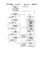
- FIGS. 5 to 10are flow charts for explaining operation of the camera shown in FIG. 3;
- FIG. 11is an outer perspective view showing a second embodiment of a fully automatic camera system according to the present invention.
- FIG. 12is an electric circuit diagram showing essential parts of a peripheral device shown in FIG. 11;
- FIG. 13is a flow chart for explaining operation of the camera shown in FIG. 11;
- FIG. 14is a flow chart for explaining operations of a sub-CPU in the peripheral device shown in FIG. 12;
- FIG. 15is a diagram showing a modification of the second embodiment of the present invention shown in FIG. 11.
- Embodiments of a program rewritable camera according to the present inventioncomprise a first memory in which a software for effecting fundamental functions of camera operation has been stored as the first memory 4 within the program rewritable camera 1 shown in FIG. 1 and a second memory into which a software for effecting photographer desired functions is externally inputted and stored, thereby controlling camera operations on the basis of the software stored in the first and second memories with the result of eliminating the complication in operating members of a conventional multi-function camera.
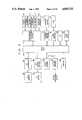
- FIG. 2is a block diagram of a control system for a fully automatic single-lens reflex camera to which the present invention is applied, which will be described in FIGS. 3 to 15.
- a photometry/exposure control circuit 11, winding motor control circuit 16, LCD driver 18, DX circuit 20, lens data circuit 21, AF interface circuit 22, AF motor control circuit 24, first memory circuit 26, second memory circuit 27 and switch group 28 including various switchesare connected to a main CPU 10.
- the photometry/exposure control circuit 11has the functions of making the A/D conversion of outputs from a first photometric element 12 which effects photometry of the center of an image plane and a second photometric element 13 which effects photometry of the periphery of an image plane and of transferring the converted outputs to the main CPU 10, of controlling a motor 14 for controlling a diaphragm aperture (hereinafter referred to as an AV motor), and of controlling a magnet 15 for controlling a shutter (hereinafter referred to as a shutter magnet).
- the winding motor control circuit 16controls a winding motor 17 in response to a control signal from the main CPU 10.
- the LCD driver 18is a driver for displaying a shutter speed, diaphragm information and the like on an LCD 19 of a dot matrix type.
- the DX circuit 20reads a DX code from a film cartridge and transfers it to the main CPU 10.
- the lens data circuit 21reads information peculiar to an interchangeable lens stored thereon (a fully open F number, minimum F number, focal length, AF coefficients or the like) and transfers it to the main CPU 10.
- An AF interface circuit 22effects the A/D conversion of an output from an AF sensor 23 and transfers it to the main CPU 10.
- An AF motor control circuit 24controls an AF motor 25 on the basis of a control signal from the main CPU 10.
- a first memory circuit 26stores a software program for effecting fundamental operations of a camera operation sequence.
- a second memory circuit 27reads a software program for effecting functions which are desired by a photographer from an outer peripheral device and
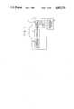
- a camera body 30is provided with a power switch button 31, release button 32 of the two step structure, UP switch 33, DOWN switch 34 and liquid crystal display board 35.
- a peripheral device 36is removably connected to a mount 30a of the camera body 30 by a connect cable 39.
- a software programis selectively set from a memory device 37 in which a plurality of photographer's desired softwares have been stored (hereinafter referred to as a ROM pack)
- the software within the ROM pack 37is transferred to the second memory circuit 27 (see FIG. 2) in the camera body by operation of an OUT button 38.
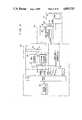
- FIG. 4is an electric circuit diagram of essential parts of the camera system mentioned above.
- a two-state switch 40which is opened and closed in response to the power switch button 31, (hereinafter referred to as a power switch), is closed, a power voltage Vcc is applied to the main CPU 10, first memory circuit 26 (hereinafter referred to as a ROM) and second memory circuit 27 (hereinafter referred to as an E 2 PROM) and a power-on reset is set to the main CPU 10 by a combination of a resistor 42 and a capacitor 43.
- the E 2 PROM 27refers to a non-volatile reading and writing memory.
- the main CPU 10controls an object 48 to be controlled on the basis of two memory circuits of ROM 26 and E 2 PROM 27.
- Push switches 46 and 47are closed in response to the release button.
- the push switch 46is closed by the first step of the release button and the push switch 47 is closed by the second step thereof.
- Push switches 44 and 45are closed respectively in response to the UP button 33 and DOWN button 34 and their functions are switched by a software program stored in the E 2 PROM 27.
- a one-shot pulse circuit 49delivers an interruption signal WINT to the main CPU 10.
- a ROM 52 within the ROM pack 37is mounted on the peripheral device 36, an address bus and a data bus are shared with the main CPU 10 in the camera body 30.
- a routine ⁇ Photometry>is called, which is a software stored in the E 2 PROM 27. In other words, it is a software program transferred from the ROM pack 37 selected by a photographer (Details will be described later).
- routine ⁇ Photometry>while photometric modes vary with respective ROM packs, display of a shutter speed and diaphragm aperture based on photometric values are made in common.
- a photometry timerwhich controls a period of photometry operation is set to enable interruption of the timer and await the half-depression of the release button 32, that is, the close of the push switch 46.
- the flowjumps to a routine ⁇ AF> which has been stored within the E 2 PROM 27 and which is a software program originally transferred from the ROM52 in the ROM pack 37.
- the routine of the main CPU conducting interruptionincludes a TIMER interruption, WRITE (write) interruption, REL(release) interruption and RELOFF(release off) interruption.
- the TIMER interruptionis to enable a photometry display operation to be periodically conducted and a routine ⁇ Photometry> is conducted each time of the interruption.
- the WRITE interruptionoccurs by an interruption signal WINT which is delivered from the one-shot pulse generator 49 in the peripheral device 36. This is a routine in which contents of the ROM 52 in the ROM pack 37 are transferred to the E 2 PROM.
- the REL interruptionoccurs when the push switch 47 is closed by the deep depression of the release button 32 to its second step. After all interruptions are inhibited, routines ⁇ Photometry>, ⁇ Release> and ⁇ Winding> are continuously conducted.
- the RELOFF interruptionoccurs when the half-depression of the release button 32 is released during an AF operation, that is, the push switch 46 is opened and returns to the routine ⁇ Power-on reset> by interrupting the AF operation which has been conducted so far.
- AF operationis defined by two of an "AF single operation” and an “AF continuous operation”
- photometry operationis defined by three of an "average photometry program AE", "variable center-weighted photometry program AE” and "average photometry aperture-priority AE".
- the ROM pack 37is provided with six kinds of combinations of the AF and photometry operations. In other words, some of all addresses in the ROM 52 may be allotted separately to the AF and photometry operations.
- FIG. 6is a flow chart of a routine ⁇ AF single> when an AF single mode (one-shot AF mode) is selected as an AF routine.
- the RELOFF interruptionis enabled and then the TIMER interruption is inhibited and a routine ⁇ Range detection> is conducted.
- the inhibition of the TIMER interruptionis to eliminate errors in range detecting data caused by occurrence of interruption during the range detection. Consequently, when the routine ⁇ Range detection> is completed, interruption is again enabled.
- the routine ⁇ Range detection>detects differences of amount and direction in a focused point of an object being photographed by the AF sensor 23 and takes in from the AF interface circuit 22. A condition of the object is judged from the taken in data regarding whether it is in a low contrast.
- This operationis repeated until an in-focus condition is obtained.
- FIG. 7is a flow chart of a routine ⁇ AF continuous> when an AF continuous mode is selected.
- the routineis substantially the same as the routine ⁇ AF single>.
- the AF continuous modeeven once focused, only interruption of a release operation is enabled and the next AF operation is immediately initiated. Consequently, when the object is continuously tracked and the release button 32 is deeply depressed to its second step when focused, the release operation is performed.
- the lens scan operation when the object is in a low contrastis not conducted, the release interruption is inhibited, an in-focus display is turned off and the range detection is immediately resumed.
- an "average photometry program AE"is selected as a photometry routine will be described with reference to a routine ⁇ Photometry 1> shown in FIG. 8.
- routine ⁇ Photometry 1>an ISO sensitivity of a film is first taken in the main CPU 10 from the DX circuit 20 as an SV value.
- brightness values BV1 and BV2 of an object being photographed in respective first and second photometry circuits 12 and 13are taken in from the photometry/exposoure control circuit 11 and an average value BV is calculated.
- a routine ⁇ AV/TV calculation>a programmed optimum aperture and a shutter speed are calculated based on the SV value, BV value, fully open F No. of a lens (AVo), minimum F No. (AVm), maximum shutter time (TVm), minimum shutter time (TVo) and the like.
- an apertureis corrected by a value in the register N and a shutter speed (TV value) is corrected correspondingly.
- a scope of the correctionis not in excess of the foregoing minimum FNo. (AVm), fully open F No. (AVo), maximum shutter time (TVm) and minimum shutter time (TVo). In other words, this is to shift programmed AV and TV values within a scope of proper exposure by depressing the UP button 33 or the DOWN button 34 by a photographer.
- the UP and DOWN buttons 33, 34serve as a program shift button.
- the present AF and photometry modesare displayed on the LCD 19 with a dot matrix type display through the LCD driver 18.
- functions of the UP and DOWN buttons 33, 34are also displayed on the LCD 19. Consequently, a structure of the display varies with the software stored in the E 2 PROM 27, that is, the one externally inputted.
- a "variable center-weighted photometry program AE"is selected as a photometry routine will be described with reference to a routine ⁇ Photometry2> shown in FIG. 9.
- the UP and DOWN buttons 33, 34serve as switching buttons for changing a ratio in the center-weighted photometry as compared with the foregoing routine ⁇ Photometry 1>.
- the flowreads in SV, BV1, and BV2 values in a manner similar to the routine ⁇ Photometry 1> and when the operation is at a first time, 5 is stored in a register M. If not a first time, judging whether the UP button 33 is on, if so, 1 is added to the register M. If not, then follows check of a condition of the DOWN button 34. If the DOWN button 34 is on, 1 is subtracted from the register M. The numerical value to be stored in the register M are not in excess of 1 to 10.
- the BV valueis calculated. Specifically, the variable center-weighted photometry is realized by obtaining the BV value by giving weight stored in the register M to a brightness BV1 in the center of a picture plane and a brightness BV2 in the periphery thereof. Then follows calculation of a diaphragm aperture and shutter speed in a routine ⁇ AT/TV calculation>. These values are displayed on the LCD 19 together with display of AF and photometry modes and display of functions of the UP and DOWN buttons 33, 34.
- an EV valueis calculated, if the operation is at a first time, a diaphragm aperture and shutter speed are properly set in an ordinary routine ⁇ AV/TV calculation>.
- an AD valueis shiftable from the minimum F No. (AVm) to the fully open FNo. (AVo) in accordance with conditions of the UP and DOWN buttons 33, 34. Consequently, the UP and DOWN buttons 33, 34 in this case serve as a shift button of an AV value.
- AVmminimum F No.
- AVofully open FNo.
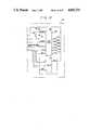
- FIG. 11A second embodiment of the present invention will be described with reference to FIGS. 11 and 12.
- a plurality of additional functionsare stored in a ROM of a large capacity in a peripheral device so as to transfer functions which a photographer desires to a memory in the camera body.
- a peripheral device 53is adapted to be connected to a mount 30a of the camera body 30 by a connect cable 61.
- AF single button 54 and AF continuous button 55for selecting AF modes
- Photometry 1 button 56, Photometry 2 button 57, Photometry 3 button 58, OUT button 59 and RESET button 60for selecting photometry modes.
- FIG. 12shows an electric circuit of the peripheral device 53.
- an electric circuit of the camera body 30is the same as that shown in FIG. 4, it is omitted.
- a sub-CPU 62 and a ROM 63are connected to the camera body, they share an address bus and data bus with the main CPU 10 in the camera body 30.
- a power voltage Vccis supplied to the sub-CPU 62 and ROM 63 from the camera body 30 and a power-on reset is set to the sub-CPU 62 by a combination of a resistor 65 and a capacitor 72.
- Push switches 66, 67, 68, 69, 70 and 71are closed in response to the AF single button 54, AF continuous button 55, Photometry 1 button 56, Photometry 2 button 57, Photometry 3 button 58 and OUT button 59.
- a push switch 64is closed in response to the RESET button 60 to set the sub-CPU 62 to a reset.
- the sub-CPU 62extracts subroutines for conducting functions selected by a photographer from the ROM 63 in the peripheral device 53 and transfers them to the E 2 PROM 27 in the camera body, operations of the main CPU 10 only differs from those of the first embodiment in a routine ⁇ WRITE interruption>, as shown in FIG. 13.
- the routine ⁇ WRITE interruption> shown in FIG. 13will be described.
- the interruptionoccurs when the sub-CPU 62 renders an interruption signal WINT "L" to the main CPU 10.
- an R/W signalis turned to "L” to render the E 2 PROM in the WRITE mode, thereafter awaiting until the interruption signal WINT becomes "H".
- the R/W signalis returned to "H” to return to a routine ⁇ Power-on reset>.
- FIG. 14shows a flow chart of operations of the sub-CPU 62 in the peripheral device 53.
- the sub-CPU 62conducts the routine ⁇ Power-on reset>.
- an address (ADR 1 address) in which the routine ⁇ Photometry 1> has been storedis stored in a register IX and an address (ADR 4 address) in which the routine ⁇ AF single> has been stored is stored in a register IY.
- ADR 4 addressaddress in which the routine ⁇ AF single> has been stored
- checking conditions of switches, if any switches are on, ROM addresses which have stored software routines of functions corresponding to the switchesare stored in the register IX or IY. This operation is continued until a switch 71 of the OUT button 59 turns on.
- the interruption signal WINTis rendered "L" to set a WRITE interruption to the main CPU 10.
- an address into which a photometry routine is to be transferredis stored in a register IW and an address into which an AF routine is to be transferred is stored in a register IZ.
- contents of an address which is indicated by the register IXare read in an accumulator (Acc) to store them in an address indicated by the register IW.
- Accaccumulator
- This operationis continued to the final address of the photometry routine.
- contents of an address indicated by the register IYare stored in an address indicated by the register IZ, in a manner similar to the above operation. This operation is repeated to the final address of the AF routine.
- the signal WINTis rendered "H" to check again conditions of switches responding to the operating buttons.
- FIG. 15is a modification of the second embodiment of the present invention.
- the distinction between the modification and the second embodimentis that switch inputs are replaced by bar code inputs given by a bar code reader.
- examples of bar codesare Photometry 1, Photometry 2, Photometry 3, AF single and AF continuous (84 to 88). It is possible to select a desired function by inputting it with a bar code reader 83 in a manner similar to the switch input.
- first and second embodimentswhile a photographer selects desired functions and stores them in the camera body, it is possible to have functions other than those presented by a camera manufacturer by preparing and transferring softwares by a photographer himself.
- E 2 PROMis employed as a memory on the camera side, the same effects can be obtained even when a RAM having a backup function or a magnetic memory is employed.
- all memories within the camera bodymay be rewritable with the E 2 PROM.
- the second memory and data input portions within the camera bodyare rendered removable from the camera body, a photographer can select one of a plurality of prepared second memories to use it as occasion arises.
Landscapes
- Physics & Mathematics (AREA)
- General Physics & Mathematics (AREA)
- Exposure Control For Cameras (AREA)
Abstract
Description
Claims (20)
Priority Applications (1)
| Application Number | Priority Date | Filing Date | Title |
|---|---|---|---|
| US07/216,761US4853733A (en) | 1988-07-08 | 1988-07-08 | Program rewritable camera |
Applications Claiming Priority (1)
| Application Number | Priority Date | Filing Date | Title |
|---|---|---|---|
| US07/216,761US4853733A (en) | 1988-07-08 | 1988-07-08 | Program rewritable camera |
Publications (1)
| Publication Number | Publication Date |
|---|---|
| US4853733Atrue US4853733A (en) | 1989-08-01 |
Family
ID=22808402
Family Applications (1)
| Application Number | Title | Priority Date | Filing Date |
|---|---|---|---|
| US07/216,761Expired - LifetimeUS4853733A (en) | 1988-07-08 | 1988-07-08 | Program rewritable camera |
Country Status (1)
| Country | Link |
|---|---|
| US (1) | US4853733A (en) |
Cited By (71)
| Publication number | Priority date | Publication date | Assignee | Title |
|---|---|---|---|---|
| US5001503A (en)* | 1988-05-26 | 1991-03-19 | Nikon Corporation | Camera |
| US5005039A (en)* | 1988-05-17 | 1991-04-02 | Minolta Camera Kabushiki Kaisha | Autofocusing camera |
| US5030979A (en)* | 1988-08-01 | 1991-07-09 | Asahi Kogaku Kogyo Kabushiki Kaisha | Electronically controlled camera |
| US5060005A (en)* | 1988-11-17 | 1991-10-22 | Olympus Optical Co., Ltd. | Camera system |
| FR2662322A1 (en)* | 1990-05-15 | 1991-11-22 | Asahi Optical Co Ltd | FIXED IMAGE ELECTRONIC CAMERA AND MAGNETIC DISC. |
| US5079573A (en)* | 1988-05-26 | 1992-01-07 | Nikon Corporation | Camera |
| US5097283A (en)* | 1989-12-28 | 1992-03-17 | Canon Kabushiki Kaisha | Camera |
| US5177526A (en)* | 1989-07-07 | 1993-01-05 | Nikon Corporation | System for inputting information into camera |
| US5187517A (en)* | 1990-10-15 | 1993-02-16 | Olympus Optical Co., Ltd. | Camera controllable with use of a control program |
| US5189466A (en)* | 1990-12-20 | 1993-02-23 | Nikon Corporation | Information setting apparatus in a camera |
| US5198851A (en)* | 1991-02-06 | 1993-03-30 | Nikon Corporation | Camera system |
| US5227835A (en)* | 1990-12-21 | 1993-07-13 | Eastman Kodak Company | Teachable camera |
| US5227824A (en)* | 1991-08-07 | 1993-07-13 | Fuji Photo Film Co., Ltd. | Zoom camera and method of automatic zooming and framing |
| US5278603A (en)* | 1989-12-28 | 1994-01-11 | Canon Kabushiki Kaisha | Camera |
| US5278604A (en)* | 1991-01-18 | 1994-01-11 | Canon Kabushiki Kaisha | Information processing system for camera |
| US5278606A (en)* | 1990-06-07 | 1994-01-11 | Canon Kabushiki Kaisha | Camera |
| US5331345A (en)* | 1991-06-21 | 1994-07-19 | Canon Kabushiki Kaisha | Television camera device |
| US5343267A (en)* | 1991-07-31 | 1994-08-30 | Canon Kabushiki Kaisha | Camera |
| US5376981A (en)* | 1992-07-03 | 1994-12-27 | Olympus Optical Co., Ltd. | Data recording apparatus for a camera |
| US5381207A (en)* | 1989-12-28 | 1995-01-10 | Canon Kabushiki Kaisha | Optical apparatus responsive to an external information output device |
| US5416556A (en)* | 1991-02-06 | 1995-05-16 | Nikon Corporation | Custom mode control apparatus in a camera |
| US5446518A (en)* | 1989-05-29 | 1995-08-29 | Canon Kabushiki Kaisha | Automatic exposure control apparatus |
| US5477264A (en)* | 1994-03-29 | 1995-12-19 | Eastman Kodak Company | Electronic imaging system using a removable software-enhanced storage device |
| US5500701A (en)* | 1992-10-26 | 1996-03-19 | Olympus Optical Co., Ltd. | Data recording module device for camera and camera system using the same |
| US5543885A (en)* | 1992-08-19 | 1996-08-06 | Nikon Corporation | Camera system |
| US5563675A (en)* | 1992-09-30 | 1996-10-08 | Lifetouch Portrait Studios, Inc. | Special effects carrier |
| US5565957A (en)* | 1993-12-27 | 1996-10-15 | Nikon Corporation | Camera |
| US5678082A (en)* | 1994-12-09 | 1997-10-14 | Olympus Optical Co., Ltd. | Electrical system apparatus including one-chip microcomputer |
| EP0552543B1 (en)* | 1992-01-21 | 1997-10-29 | Nikon Corporation | Data exchange system between camera and terminal device |
| US5721989A (en)* | 1994-05-13 | 1998-02-24 | Asahi Kogaku Kogyo Kabushiki Kaisha | Camera having a mode memory device |
| US5726737A (en)* | 1995-11-02 | 1998-03-10 | Eastman Kodak Company | System for controlling photofinishing of photosensitive material |
| US5734425A (en)* | 1994-02-15 | 1998-03-31 | Eastman Kodak Company | Electronic still camera with replaceable digital processing program |
| US5752089A (en)* | 1990-08-13 | 1998-05-12 | Olympus Optical Co., Ltd. | System operable with a given apparatus and capable of pseudo-rewriting a program |
| US5754227A (en)* | 1994-09-28 | 1998-05-19 | Ricoh Company, Ltd. | Digital electronic camera having an external input/output interface through which the camera is monitored and controlled |
| US5790193A (en)* | 1995-11-22 | 1998-08-04 | Eastman Kodak Company | Accessory module for an electronic camera |
| US5897228A (en)* | 1997-02-28 | 1999-04-27 | Eastman Kodak Company | Camera with low cost interchangeable pushbutton annotation |
| US6006039A (en)* | 1996-02-13 | 1999-12-21 | Fotonation, Inc. | Method and apparatus for configuring a camera through external means |
| US6035142A (en)* | 1997-02-28 | 2000-03-07 | Eastman Kodak Company | Camera with adaptive annotation recall |
| US6040856A (en)* | 1993-10-29 | 2000-03-21 | Canon Kabushiki Kaisha | Electronic camera capable of performing photography and character recognition |
| US6085024A (en)* | 1990-04-25 | 2000-07-04 | Asahi Kogaku Kogyo Kabushiki Kaisha | Electronic still camera and magnetic disk |
| EP0924553A3 (en)* | 1997-12-17 | 2000-09-06 | Canon Kabushiki Kaisha | Memory alternation system for camera and its control method |
| US6219494B1 (en) | 1998-10-08 | 2001-04-17 | Olympus Optical Co., Ltd. | Peripheral and camera system using the same, for rewriting programs stored in a camera |
| US20010017656A1 (en)* | 2000-02-25 | 2001-08-30 | Asahi Kogaku Kogyo Kabushiki Kaisha | Internet camera system |
| US20010017655A1 (en)* | 2000-02-28 | 2001-08-30 | Asahi Kogaku Kogyo Kabushiki Kaisha | Internet camera |
| US20010025303A1 (en)* | 2000-03-06 | 2001-09-27 | Fisher Clay H. | System and method for accessing and utilizing ancillary data with an electronic camera device |
| US20010024232A1 (en)* | 2000-02-18 | 2001-09-27 | Asahi Kogaku Kogyo Kabushiki Kaisha | Internet camera |
| US6300976B1 (en) | 1994-09-28 | 2001-10-09 | Ricoh Company, Ltd. | Digital image capturing device having an input/output interface through which the device is controlled |
| US6327001B1 (en)* | 1992-12-01 | 2001-12-04 | Canon Kabushiki Kaisha | Image processing system and information processing apparatus |
| US20020053087A1 (en)* | 2000-10-27 | 2002-05-02 | Asahi Kogaku Kogyo Kabushiki Kaisha | Internet camera system |
| US6452629B1 (en)* | 1995-03-15 | 2002-09-17 | Canon Kabushiki Kaisha | System for installing image sensing program |
| EP1130901A3 (en)* | 1999-11-16 | 2003-02-12 | Minolta Co., Ltd. | Digital camera with card slot |
| US20030074556A1 (en)* | 2001-10-17 | 2003-04-17 | Chapman Charles B. | Chain of custody system and method |
| US20030169342A1 (en)* | 1998-11-06 | 2003-09-11 | Eran Steinberg | Method and apparatus for controlled camera useability |
| US20040218208A1 (en)* | 2002-07-26 | 2004-11-04 | Kunihiro Akiyoshi | Image forming apparatus, information processing apparatus, program execution method and program producing method |
| US20050010914A1 (en)* | 2003-07-10 | 2005-01-13 | Wan-Pei Liang | Method for upgrading firmware |
| US20050055727A1 (en)* | 1997-12-04 | 2005-03-10 | Pentax U.S.A., Inc. | Integrated internet/intranet camera |
| US6972789B1 (en)* | 1999-07-21 | 2005-12-06 | Csnon Kabushiki Kaisha | Electronic device, control method therefor, and storage medium |
| US7015959B1 (en)* | 1999-03-23 | 2006-03-21 | Canon Kabushiki Kaisha | Image pickup apparatus for picking up and recording still or moving images and a method for controlling the same |
| US7232072B1 (en)* | 1992-03-12 | 2007-06-19 | Intermec Ip Corp. | Combined code reader and digital camera |
| EP2133792A1 (en)* | 2008-06-13 | 2009-12-16 | Nintendo Co., Ltd. | Information-processing apparatus, and storage medium storing launch program executed by information-processing apparatus |
| EP2133791A1 (en)* | 2008-06-13 | 2009-12-16 | Nintendo Co., Limited | Information-processing apparatus, and storage medium storing boot program executed by information-processing apparatus |
| US20110122278A1 (en)* | 2009-11-26 | 2011-05-26 | Samsung Electronics Co., Ltd. | Digital photographing apparatus, method of controlling the same, and recording medium storing the method |
| USRE42973E1 (en) | 1996-02-13 | 2011-11-29 | Scenera Technologies, Llc | Camera network communication device |
| US8102457B1 (en) | 1997-07-09 | 2012-01-24 | Flashpoint Technology, Inc. | Method and apparatus for correcting aspect ratio in a camera graphical user interface |
| US8127232B2 (en) | 1998-12-31 | 2012-02-28 | Flashpoint Technology, Inc. | Method and apparatus for editing heterogeneous media objects in a digital imaging device |
| CN101252645B (en)* | 2007-02-19 | 2013-03-13 | 佳能株式会社 | Camera, accessory, and camera system |
| US9224145B1 (en) | 2006-08-30 | 2015-12-29 | Qurio Holdings, Inc. | Venue based digital rights using capture device with digital watermarking capability |
| US9264694B2 (en) | 2007-08-29 | 2016-02-16 | Nintendo Co., Ltd. | Hand-held imaging apparatus and storage medium storing program |
| US9630099B2 (en) | 2008-10-01 | 2017-04-25 | Nintendo Co., Ltd. | Information processing device, information processing system, and launch program and storage medium storing the same providing photographing functionality |
| US10051363B2 (en)* | 2016-09-16 | 2018-08-14 | Gopro, Inc. | Submersible microphone system with a compressible spacer |
| EP3640729A1 (en)* | 2018-10-12 | 2020-04-22 | Canon Kabushiki Kaisha | Imaging apparatus, accessory apparatus and control methods therefor |
Citations (7)
| Publication number | Priority date | Publication date | Assignee | Title |
|---|---|---|---|---|
| US4384771A (en)* | 1975-01-24 | 1983-05-24 | Canon Kabushiki Kaisha | Data registration device |
| US4455068A (en)* | 1980-12-11 | 1984-06-19 | Minolta Camera Kabushiki Kaisha | Camera capable of programmed exposure control |
| US4477164A (en)* | 1981-12-17 | 1984-10-16 | Minolta Camera Kabushiki Kaisha | Camera system operable in accordance with stored memory |
| US4519692A (en)* | 1983-04-08 | 1985-05-28 | Warner-Lambert Technologies, Inc. | Exposure and camera control |
| US4728978A (en)* | 1986-03-07 | 1988-03-01 | Minolta Camera Kabushiki Kaisha | Photographic camera |
| US4733265A (en)* | 1986-06-13 | 1988-03-22 | Canon Kabushiki Kaisha | Data retaining apparatus for a camera |
| US4769665A (en)* | 1983-03-10 | 1988-09-06 | Victor Hasselbad Aktiebolag | Arrangement for system cameras |
- 1988
- 1988-07-08USUS07/216,761patent/US4853733A/ennot_activeExpired - Lifetime
Patent Citations (8)
| Publication number | Priority date | Publication date | Assignee | Title |
|---|---|---|---|---|
| US4384771A (en)* | 1975-01-24 | 1983-05-24 | Canon Kabushiki Kaisha | Data registration device |
| US4449805A (en)* | 1975-01-24 | 1984-05-22 | Canon Kabushiki Kaisha | Data registration device |
| US4455068A (en)* | 1980-12-11 | 1984-06-19 | Minolta Camera Kabushiki Kaisha | Camera capable of programmed exposure control |
| US4477164A (en)* | 1981-12-17 | 1984-10-16 | Minolta Camera Kabushiki Kaisha | Camera system operable in accordance with stored memory |
| US4769665A (en)* | 1983-03-10 | 1988-09-06 | Victor Hasselbad Aktiebolag | Arrangement for system cameras |
| US4519692A (en)* | 1983-04-08 | 1985-05-28 | Warner-Lambert Technologies, Inc. | Exposure and camera control |
| US4728978A (en)* | 1986-03-07 | 1988-03-01 | Minolta Camera Kabushiki Kaisha | Photographic camera |
| US4733265A (en)* | 1986-06-13 | 1988-03-22 | Canon Kabushiki Kaisha | Data retaining apparatus for a camera |
Cited By (144)
| Publication number | Priority date | Publication date | Assignee | Title |
|---|---|---|---|---|
| US5005039A (en)* | 1988-05-17 | 1991-04-02 | Minolta Camera Kabushiki Kaisha | Autofocusing camera |
| US5079573A (en)* | 1988-05-26 | 1992-01-07 | Nikon Corporation | Camera |
| US5001503A (en)* | 1988-05-26 | 1991-03-19 | Nikon Corporation | Camera |
| US5084720A (en)* | 1988-05-26 | 1992-01-28 | Nikon Corporation | Camera accessory having data communication and printing capability |
| US5030979A (en)* | 1988-08-01 | 1991-07-09 | Asahi Kogaku Kogyo Kabushiki Kaisha | Electronically controlled camera |
| US5060005A (en)* | 1988-11-17 | 1991-10-22 | Olympus Optical Co., Ltd. | Camera system |
| US5446518A (en)* | 1989-05-29 | 1995-08-29 | Canon Kabushiki Kaisha | Automatic exposure control apparatus |
| US5177526A (en)* | 1989-07-07 | 1993-01-05 | Nikon Corporation | System for inputting information into camera |
| US5097283A (en)* | 1989-12-28 | 1992-03-17 | Canon Kabushiki Kaisha | Camera |
| EP0435280B1 (en)* | 1989-12-28 | 1996-09-11 | Canon Kabushiki Kaisha | Optical apparatus responsive to an external information output device |
| US5278603A (en)* | 1989-12-28 | 1994-01-11 | Canon Kabushiki Kaisha | Camera |
| US5381207A (en)* | 1989-12-28 | 1995-01-10 | Canon Kabushiki Kaisha | Optical apparatus responsive to an external information output device |
| US6085024A (en)* | 1990-04-25 | 2000-07-04 | Asahi Kogaku Kogyo Kabushiki Kaisha | Electronic still camera and magnetic disk |
| FR2662322A1 (en)* | 1990-05-15 | 1991-11-22 | Asahi Optical Co Ltd | FIXED IMAGE ELECTRONIC CAMERA AND MAGNETIC DISC. |
| US5278606A (en)* | 1990-06-07 | 1994-01-11 | Canon Kabushiki Kaisha | Camera |
| US5752089A (en)* | 1990-08-13 | 1998-05-12 | Olympus Optical Co., Ltd. | System operable with a given apparatus and capable of pseudo-rewriting a program |
| US5300978A (en)* | 1990-10-15 | 1994-04-05 | Olympus Optical Co., Ltd. | Camera with display for displaying a control operation to be executed |
| US5187517A (en)* | 1990-10-15 | 1993-02-16 | Olympus Optical Co., Ltd. | Camera controllable with use of a control program |
| US5189466A (en)* | 1990-12-20 | 1993-02-23 | Nikon Corporation | Information setting apparatus in a camera |
| US5227835A (en)* | 1990-12-21 | 1993-07-13 | Eastman Kodak Company | Teachable camera |
| US5278604A (en)* | 1991-01-18 | 1994-01-11 | Canon Kabushiki Kaisha | Information processing system for camera |
| US5198851A (en)* | 1991-02-06 | 1993-03-30 | Nikon Corporation | Camera system |
| US5416556A (en)* | 1991-02-06 | 1995-05-16 | Nikon Corporation | Custom mode control apparatus in a camera |
| US5331345A (en)* | 1991-06-21 | 1994-07-19 | Canon Kabushiki Kaisha | Television camera device |
| US5343267A (en)* | 1991-07-31 | 1994-08-30 | Canon Kabushiki Kaisha | Camera |
| US5227824A (en)* | 1991-08-07 | 1993-07-13 | Fuji Photo Film Co., Ltd. | Zoom camera and method of automatic zooming and framing |
| EP0552543B1 (en)* | 1992-01-21 | 1997-10-29 | Nikon Corporation | Data exchange system between camera and terminal device |
| US7232072B1 (en)* | 1992-03-12 | 2007-06-19 | Intermec Ip Corp. | Combined code reader and digital camera |
| US5453805A (en)* | 1992-07-03 | 1995-09-26 | Olympus Optical Co., Ltd. | Data recording apparatus for a camera |
| US5376981A (en)* | 1992-07-03 | 1994-12-27 | Olympus Optical Co., Ltd. | Data recording apparatus for a camera |
| US5543885A (en)* | 1992-08-19 | 1996-08-06 | Nikon Corporation | Camera system |
| US5563675A (en)* | 1992-09-30 | 1996-10-08 | Lifetouch Portrait Studios, Inc. | Special effects carrier |
| US5500701A (en)* | 1992-10-26 | 1996-03-19 | Olympus Optical Co., Ltd. | Data recording module device for camera and camera system using the same |
| US6327001B1 (en)* | 1992-12-01 | 2001-12-04 | Canon Kabushiki Kaisha | Image processing system and information processing apparatus |
| US6630949B1 (en) | 1992-12-01 | 2003-10-07 | Canon Kabushiki Kaisha | Image processing system and information processing apparatus |
| US6040856A (en)* | 1993-10-29 | 2000-03-21 | Canon Kabushiki Kaisha | Electronic camera capable of performing photography and character recognition |
| US5565957A (en)* | 1993-12-27 | 1996-10-15 | Nikon Corporation | Camera |
| US5734425A (en)* | 1994-02-15 | 1998-03-31 | Eastman Kodak Company | Electronic still camera with replaceable digital processing program |
| US5477264A (en)* | 1994-03-29 | 1995-12-19 | Eastman Kodak Company | Electronic imaging system using a removable software-enhanced storage device |
| US5721989A (en)* | 1994-05-13 | 1998-02-24 | Asahi Kogaku Kogyo Kabushiki Kaisha | Camera having a mode memory device |
| US6300976B1 (en) | 1994-09-28 | 2001-10-09 | Ricoh Company, Ltd. | Digital image capturing device having an input/output interface through which the device is controlled |
| US5754227A (en)* | 1994-09-28 | 1998-05-19 | Ricoh Company, Ltd. | Digital electronic camera having an external input/output interface through which the camera is monitored and controlled |
| US7432952B2 (en)* | 1994-09-28 | 2008-10-07 | Ricoh Company, Ltd. | Digital image capturing device having an interface for receiving a control program |
| US20020054212A1 (en)* | 1994-09-28 | 2002-05-09 | Hiroki Fukuoka | Digital electronic still camera which receives an input/output control program through a detachable communication interface card |
| US5678082A (en)* | 1994-12-09 | 1997-10-14 | Olympus Optical Co., Ltd. | Electrical system apparatus including one-chip microcomputer |
| US6452629B1 (en)* | 1995-03-15 | 2002-09-17 | Canon Kabushiki Kaisha | System for installing image sensing program |
| US7420597B2 (en) | 1995-03-15 | 2008-09-02 | Canon Kabushiki Kaisha | System for installing image sensing program |
| US20020186303A1 (en)* | 1995-03-15 | 2002-12-12 | Takashi Aizawa | System for installing image sensing program |
| US5726737A (en)* | 1995-11-02 | 1998-03-10 | Eastman Kodak Company | System for controlling photofinishing of photosensitive material |
| US5790193A (en)* | 1995-11-22 | 1998-08-04 | Eastman Kodak Company | Accessory module for an electronic camera |
| USRE42973E1 (en) | 1996-02-13 | 2011-11-29 | Scenera Technologies, Llc | Camera network communication device |
| US6006039A (en)* | 1996-02-13 | 1999-12-21 | Fotonation, Inc. | Method and apparatus for configuring a camera through external means |
| US6035142A (en)* | 1997-02-28 | 2000-03-07 | Eastman Kodak Company | Camera with adaptive annotation recall |
| US5897228A (en)* | 1997-02-28 | 1999-04-27 | Eastman Kodak Company | Camera with low cost interchangeable pushbutton annotation |
| US8970761B2 (en) | 1997-07-09 | 2015-03-03 | Flashpoint Technology, Inc. | Method and apparatus for correcting aspect ratio in a camera graphical user interface |
| US8102457B1 (en) | 1997-07-09 | 2012-01-24 | Flashpoint Technology, Inc. | Method and apparatus for correcting aspect ratio in a camera graphical user interface |
| US7425987B2 (en) | 1997-12-04 | 2008-09-16 | Pentax Of America, Inc. | Method of transmitting image data from standalone device |
| US7962946B2 (en) | 1997-12-04 | 2011-06-14 | Axis Ab | Camera connectible to CCTV network |
| US7640568B2 (en) | 1997-12-04 | 2009-12-29 | Pentax Of America, Inc. | Integrated internet camera |
| US7644431B2 (en) | 1997-12-04 | 2010-01-05 | Pentax Of America, Inc. | Method for sending image data from camera to CCTV network |
| US7640567B2 (en) | 1997-12-04 | 2009-12-29 | Pentax Of America, Inc. | Camera connectible to CCTV network |
| US20100023981A1 (en)* | 1997-12-04 | 2010-01-28 | Pentax Of America, Inc. | Method for sending image data from camera to cctv network |
| US9143672B2 (en) | 1997-12-04 | 2015-09-22 | Axis Ab | Device for sending image data from camera to CCTV network |
| US20050055727A1 (en)* | 1997-12-04 | 2005-03-10 | Pentax U.S.A., Inc. | Integrated internet/intranet camera |
| US20050078189A1 (en)* | 1997-12-04 | 2005-04-14 | Pentax U.S.A., Inc. | Integrated Internet camera |
| US20050099519A1 (en)* | 1997-12-04 | 2005-05-12 | Pentax U.S.A., Inc. | Integrated internet camera |
| US20050144653A1 (en)* | 1997-12-04 | 2005-06-30 | Pentax U.S.A., Inc. | Method of transmitting image data from standalone device |
| US20050146610A1 (en)* | 1997-12-04 | 2005-07-07 | Pentax U.S.A., Inc. | Camera connectible to CCTV network |
| US20050146609A1 (en)* | 1997-12-04 | 2005-07-07 | Pentax U.S.A., Inc. | Method for sending image data from camera to CCTV network |
| US20050149979A1 (en)* | 1997-12-04 | 2005-07-07 | Pentax U.S.A., Inc. | Standalone device connectible to CCTV network |
| US20110197241A1 (en)* | 1997-12-04 | 2011-08-11 | Axis Ab | Device for sending image data from camera to cctv network |
| US7350224B2 (en) | 1997-12-04 | 2008-03-25 | Pentax Of America, Inc. | Integrated internet/intranet camera |
| US7631335B2 (en) | 1997-12-04 | 2009-12-08 | Pentax Of America, Inc. | Integrated internet camera |
| US9621778B2 (en) | 1997-12-04 | 2017-04-11 | Axis Ab | Device for sending image data from camera to CCTV network |
| US20100023982A1 (en)* | 1997-12-04 | 2010-01-28 | Pentax Of America, Inc. | Camera connectible to cctv network |
| US20060031901A1 (en)* | 1997-12-04 | 2006-02-09 | Pentax Of America, Inc. | Integrated internet camera |
| US7962945B2 (en) | 1997-12-04 | 2011-06-14 | Axis Ab | Method for sending image data from camera to cctv network |
| US7523480B2 (en) | 1997-12-04 | 2009-04-21 | Pentax Of America, Inc. | Integrated Internet camera |
| US7523481B2 (en) | 1997-12-04 | 2009-04-21 | Pentax Of America, Inc. | Integrated internet camera |
| US7428005B2 (en) | 1997-12-04 | 2008-09-23 | Pentax Of America, Inc. | Integrated Internet/intranet camera |
| US7428004B2 (en) | 1997-12-04 | 2008-09-23 | Pentax Of America, Inc. | Standalone device connectible to CCTV network |
| US7272845B2 (en) | 1997-12-04 | 2007-09-18 | Pentax Of America, Inc. | Integrated internet/intranet camera |
| US8381255B2 (en) | 1997-12-04 | 2013-02-19 | Axis Ab | Device for sending image data from camera to CCTV network |
| US20070268373A1 (en)* | 1997-12-04 | 2007-11-22 | Pentax Of America, Inc. | Integrated internet camera |
| US20070288974A1 (en)* | 1997-12-04 | 2007-12-13 | Pentax Of America, Inc. | Integrated internet camera |
| US20060031902A1 (en)* | 1997-12-04 | 2006-02-09 | Pentax Of America, Inc. | Integrated internet camera |
| US6195511B1 (en) | 1997-12-17 | 2001-02-27 | Canon Kabushiki Kaisha | Memory alteration system for camera and its control method |
| EP0924553A3 (en)* | 1997-12-17 | 2000-09-06 | Canon Kabushiki Kaisha | Memory alternation system for camera and its control method |
| EP2028541A3 (en)* | 1997-12-17 | 2011-02-16 | Canon Kabushiki Kaisha | Memory alteration system for camera and its control method |
| US6219494B1 (en) | 1998-10-08 | 2001-04-17 | Olympus Optical Co., Ltd. | Peripheral and camera system using the same, for rewriting programs stored in a camera |
| USRE39674E1 (en)* | 1998-10-08 | 2007-06-05 | Olympus Optical Co., Ltd. | Peripheral and camera system using the same, for rewriting programs stored in a camera |
| US7324133B2 (en) | 1998-11-06 | 2008-01-29 | Fotomedia Technologies, Llc | Method and apparatus for controlled camera useability |
| US20030169342A1 (en)* | 1998-11-06 | 2003-09-11 | Eran Steinberg | Method and apparatus for controlled camera useability |
| US8127232B2 (en) | 1998-12-31 | 2012-02-28 | Flashpoint Technology, Inc. | Method and apparatus for editing heterogeneous media objects in a digital imaging device |
| US8972867B1 (en) | 1998-12-31 | 2015-03-03 | Flashpoint Technology, Inc. | Method and apparatus for editing heterogeneous media objects in a digital imaging device |
| US7015959B1 (en)* | 1999-03-23 | 2006-03-21 | Canon Kabushiki Kaisha | Image pickup apparatus for picking up and recording still or moving images and a method for controlling the same |
| US6972789B1 (en)* | 1999-07-21 | 2005-12-06 | Csnon Kabushiki Kaisha | Electronic device, control method therefor, and storage medium |
| US20060007340A1 (en)* | 1999-07-21 | 2006-01-12 | Takashi Aizawa | Electronic device, control method therefor and storage medium |
| US7283160B2 (en)* | 1999-07-21 | 2007-10-16 | Canon Kabushiki Kaisha | Electronic device, control method therefor and storage medium |
| EP1130901A3 (en)* | 1999-11-16 | 2003-02-12 | Minolta Co., Ltd. | Digital camera with card slot |
| US6980232B2 (en) | 2000-02-18 | 2005-12-27 | Pentax Corporation | Image transmitting Internet camera |
| US20010024232A1 (en)* | 2000-02-18 | 2001-09-27 | Asahi Kogaku Kogyo Kabushiki Kaisha | Internet camera |
| US20010017656A1 (en)* | 2000-02-25 | 2001-08-30 | Asahi Kogaku Kogyo Kabushiki Kaisha | Internet camera system |
| US20010017655A1 (en)* | 2000-02-28 | 2001-08-30 | Asahi Kogaku Kogyo Kabushiki Kaisha | Internet camera |
| US6965398B2 (en) | 2000-02-28 | 2005-11-15 | Pentax Corporation | Internet camera |
| US20010025303A1 (en)* | 2000-03-06 | 2001-09-27 | Fisher Clay H. | System and method for accessing and utilizing ancillary data with an electronic camera device |
| US8345105B2 (en) | 2000-03-06 | 2013-01-01 | Sony Corporation | System and method for accessing and utilizing ancillary data with an electronic camera device |
| US7562380B2 (en) | 2000-10-27 | 2009-07-14 | Hoya Corporation | Internet camera system |
| US20020053087A1 (en)* | 2000-10-27 | 2002-05-02 | Asahi Kogaku Kogyo Kabushiki Kaisha | Internet camera system |
| US20030074556A1 (en)* | 2001-10-17 | 2003-04-17 | Chapman Charles B. | Chain of custody system and method |
| US6963973B2 (en) | 2001-10-17 | 2005-11-08 | Hewlett-Packard Development Company, L.P. | Chain of custody system and method |
| US7554685B2 (en) | 2002-07-26 | 2009-06-30 | Ricoh Company, Ltd. | Image forming apparatus, information processing apparatus, program execution method and program producing method |
| EP1385089A3 (en)* | 2002-07-26 | 2007-01-24 | Ricoh Company, Ltd. | Image forming apparatus, information processing apparatus, program execution method and program producing method |
| US20040218208A1 (en)* | 2002-07-26 | 2004-11-04 | Kunihiro Akiyoshi | Image forming apparatus, information processing apparatus, program execution method and program producing method |
| US20050010914A1 (en)* | 2003-07-10 | 2005-01-13 | Wan-Pei Liang | Method for upgrading firmware |
| US9224145B1 (en) | 2006-08-30 | 2015-12-29 | Qurio Holdings, Inc. | Venue based digital rights using capture device with digital watermarking capability |
| CN101252645B (en)* | 2007-02-19 | 2013-03-13 | 佳能株式会社 | Camera, accessory, and camera system |
| US9264694B2 (en) | 2007-08-29 | 2016-02-16 | Nintendo Co., Ltd. | Hand-held imaging apparatus and storage medium storing program |
| US9894344B2 (en) | 2007-08-29 | 2018-02-13 | Nintendo Co., Ltd. | Camera device |
| US9344706B2 (en) | 2007-08-29 | 2016-05-17 | Nintendo Co., Ltd. | Camera device |
| US9256449B2 (en) | 2008-06-13 | 2016-02-09 | Nintendo Co., Ltd. | Menu screen for information processing apparatus and computer-readable storage medium recording information processing program |
| US20110234857A1 (en)* | 2008-06-13 | 2011-09-29 | Nintendo Co., Ltd. | Information processing apparatus and computer-readable storage medium recording information processing program |
| US10509538B2 (en) | 2008-06-13 | 2019-12-17 | Nintendo Co., Ltd. | Information processing apparatus having a photographing-enabled state |
| US8913172B2 (en) | 2008-06-13 | 2014-12-16 | Nintendo Co., Ltd. | Information processing apparatus and computer-readable storage medium recording information processing program |
| EP2226720A1 (en)* | 2008-06-13 | 2010-09-08 | Nintendo Co., Ltd. | Information-processing apparatus, and storage medium storing boot program executed by information-processing apparatus |
| EP2133792A1 (en)* | 2008-06-13 | 2009-12-16 | Nintendo Co., Ltd. | Information-processing apparatus, and storage medium storing launch program executed by information-processing apparatus |
| US9135026B2 (en) | 2008-06-13 | 2015-09-15 | Nintendo Co., Ltd. | Information-processing apparatus having photography applications |
| EP2133791A1 (en)* | 2008-06-13 | 2009-12-16 | Nintendo Co., Limited | Information-processing apparatus, and storage medium storing boot program executed by information-processing apparatus |
| US20090310010A1 (en)* | 2008-06-13 | 2009-12-17 | Nintendo Co., Ltd. | Information processing apparatus, and computer-readable storage medium recording information processing program |
| US8130275B2 (en) | 2008-06-13 | 2012-03-06 | Nintendo Co., Ltd. | Information-processing apparatus, and storage medium storing a photographing application launch program executed by information-processing apparatus |
| US10437424B2 (en) | 2008-06-13 | 2019-10-08 | Nintendo Co., Ltd. | Information processing apparatus and computer-readable storage medium recording information processing program |
| US20090310957A1 (en)* | 2008-06-13 | 2009-12-17 | Nintendo Co., Ltd. | Information-processing apparatus, and storage medium storing launch program executed by information-processing apparatus |
| US20090310889A1 (en)* | 2008-06-13 | 2009-12-17 | Nintendo Co., Ltd. | Information-processing apparatus, and storage medium storing boot program executed by information-processing apparatus |
| US8149315B2 (en) | 2008-06-13 | 2012-04-03 | Nintendo Co., Ltd. | System and method for changing display of an image during a changed state of electronic device |
| US9630099B2 (en) | 2008-10-01 | 2017-04-25 | Nintendo Co., Ltd. | Information processing device, information processing system, and launch program and storage medium storing the same providing photographing functionality |
| US10124247B2 (en) | 2008-10-01 | 2018-11-13 | Nintendo Co., Ltd. | System and device for communicating images |
| US10525334B2 (en) | 2008-10-01 | 2020-01-07 | Nintendo Co., Ltd. | System and device for communicating images |
| US20110122278A1 (en)* | 2009-11-26 | 2011-05-26 | Samsung Electronics Co., Ltd. | Digital photographing apparatus, method of controlling the same, and recording medium storing the method |
| US8736693B2 (en)* | 2009-11-26 | 2014-05-27 | Samsung Electronics Co., Ltd. | Digital photographing apparatus that corrects hand shake, method of controlling the same, and recording medium storing the method |
| US10051363B2 (en)* | 2016-09-16 | 2018-08-14 | Gopro, Inc. | Submersible microphone system with a compressible spacer |
| US10674256B2 (en) | 2016-09-16 | 2020-06-02 | Gopro, Inc. | Submersible microphone system with a compressible spacer |
| US11363373B2 (en) | 2016-09-16 | 2022-06-14 | Gopro, Inc. | Submersible microphone system with a compressible spacer |
| US12081939B2 (en) | 2016-09-16 | 2024-09-03 | Gopro, Inc. | Submersible microphone system with a compressible spacer |
| EP3640729A1 (en)* | 2018-10-12 | 2020-04-22 | Canon Kabushiki Kaisha | Imaging apparatus, accessory apparatus and control methods therefor |
Similar Documents
| Publication | Publication Date | Title |
|---|---|---|
| US4853733A (en) | Program rewritable camera | |
| US4814812A (en) | Multimode cameras | |
| US5574926A (en) | One-chip microcomputer system having function for substantially correcting contents of program | |
| US5598242A (en) | Vibration compensation mode selection apparataus and associated visual display for a camera | |
| US7796350B2 (en) | Interchangeable lens barrel, program rewriting system for interchangeable lens barrel | |
| US4699491A (en) | Camera accessory with encoder adjusting device | |
| JP2001174690A (en) | Automatic focus adjustment device, automatic exposure device, automatic light control device, optical device and camera | |
| JPH02141715A (en) | Functional element selection camera | |
| US6055381A (en) | Silver film camera capable of displaying an electronically picked-up image | |
| US5142320A (en) | Indicating apparatus displaying enlarged information of camera | |
| US5903786A (en) | Function setting device for photographic device | |
| JP2666266B2 (en) | Fully automatic camera | |
| USRE35885E (en) | Photographing mode switching device of a camera | |
| US5649245A (en) | Camera setting and display device | |
| JP3021566B2 (en) | camera | |
| US6343191B1 (en) | Camera having both silver-salt picture-taking function and electronic-image pickup function | |
| US5642180A (en) | Photographic camera with information reading function | |
| US5895130A (en) | Auto-focus camera | |
| JP2558118Y2 (en) | Camera display device | |
| JP2576852B2 (en) | Camera system | |
| JP2723125B2 (en) | camera | |
| JPH07319049A (en) | Camera | |
| JP2723124B2 (en) | camera | |
| US6249651B1 (en) | Camera for electronic photographing and photographing using films | |
| JP2666266C (en) |
Legal Events
| Date | Code | Title | Description |
|---|---|---|---|
| AS | Assignment | Owner name:OLYMPUS OPTICAL COMPANY LIMITED, 43-2, 2-CHOME, HA Free format text:ASSIGNMENT OF ASSIGNORS INTEREST.;ASSIGNORS:WATANABE, YOUJI;MATSUZAKI, MINORU;ITOH, JUNICHI;REEL/FRAME:004924/0090 Effective date:19880628 Owner name:OLYMPUS OPTICAL COMPANY LIMITED, JAPAN Free format text:ASSIGNMENT OF ASSIGNORS INTEREST;ASSIGNORS:WATANABE, YOUJI;MATSUZAKI, MINORU;ITOH, JUNICHI;REEL/FRAME:004924/0090 Effective date:19880628 | |
| STCF | Information on status: patent grant | Free format text:PATENTED CASE | |
| CC | Certificate of correction | ||
| FEPP | Fee payment procedure | Free format text:PAYOR NUMBER ASSIGNED (ORIGINAL EVENT CODE: ASPN); ENTITY STATUS OF PATENT OWNER: LARGE ENTITY | |
| FPAY | Fee payment | Year of fee payment:4 | |
| FEPP | Fee payment procedure | Free format text:PAYOR NUMBER ASSIGNED (ORIGINAL EVENT CODE: ASPN); ENTITY STATUS OF PATENT OWNER: LARGE ENTITY Free format text:PAYER NUMBER DE-ASSIGNED (ORIGINAL EVENT CODE: RMPN); ENTITY STATUS OF PATENT OWNER: LARGE ENTITY | |
| FPAY | Fee payment | Year of fee payment:8 | |
| FPAY | Fee payment | Year of fee payment:12 | |
| AS | Assignment | Owner name:OLYMPUS CORPORATION, JAPAN Free format text:CHANGE OF NAME;ASSIGNOR:OLYMPUS OPTICAL COMPANY LIMITED;REEL/FRAME:016059/0516 Effective date:20031001 | |
| RR | Request for reexamination filed | Effective date:20050413 | |
| AS | Assignment | Owner name:OLYMPUS CORPORATION, JAPAN Free format text:CHANGE OF NAME;ASSIGNOR:OLYMPUS OPTICAL COMPANY LIMITED;REEL/FRAME:020897/0759 Effective date:20031014 | |
| B1 | Reexamination certificate first reexamination | Free format text:CLAIMS 1-15 AND 17-20 ARE CANCELLED. CLAIM 16 IS DETERMINED TO BE PATENTABLE AS AMENDED. NEW CLAIMS 21 AND 22 ARE ADDED AND DETERMINED TO BE PATENTABLE. |